Thyristor Modules Thyristor/Diode Modules - IXYS Power
Thyristor Modules Thyristor/Diode Modules - IXYS Power
Thyristor Modules Thyristor/Diode Modules - IXYS Power

You also want an ePaper? Increase the reach of your titles
YUMPU automatically turns print PDFs into web optimized ePapers that Google loves.
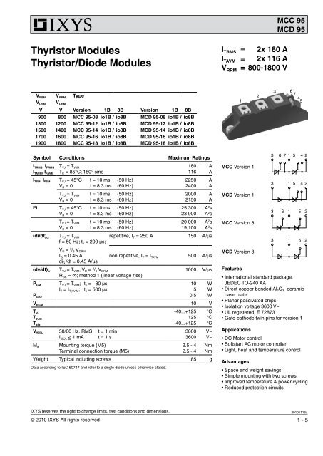
MCC 95MCD 95<strong>Thyristor</strong> <strong>Modules</strong><strong>Thyristor</strong>/<strong>Diode</strong> <strong>Modules</strong>I TRMS = 2x 180 AI TAVM = 2x 116 AV RRM = 800-1800 VV RSM V RRM TypeV DSM V DRMV V Version 1B 8B Version 1B 8B900 800 MCC 95-08 io1B / io8B MCD 95-08 io1B / io8B1300 1200 MCC 95-12 io1B / io8B MCD 95-12 io1B / io8B1500 1400 MCC 95-14 io1B / io8B MCD 95-14 io1B / io8B1700 1600 MCC 95-16 io1B / io8B MCD 95-16 io1B / io8B1900 1800 MCC 95-18 io1B / io8B MCD 95-18 io1B / io8B1236 745Symbol Conditions Maximum RatingsI TRMS , I FRMSI TAVM , I FAVMT VJ = T VJMT C = 85°C; 180° sine180116AAI TSM , I FSM T VJ = 45°C t = 10 ms (50 Hz)V R = 0 t = 8.3 ms (60 Hz)T VJ = T VJM t = 10 ms (50 Hz)V R = 0 t = 8.3 ms (60 Hz)I 2 t T VJ = 45°C t = 10 ms (50 Hz)V R = 0 t = 8.3 ms (60 Hz)T VJ = T VJM t = 10 ms (50 Hz)V R = 0 t = 8.3 ms (60 Hz)(di/dt) cr T VJ = T VJMf = 50 Hz; t p = 200 µs;225024002000215025 30023 90020 00019 100AAAAA 2 sA 2 sA 2 sA 2 srepetitive, I T = 250 A 150 A/µsMCC Version 1MCD Version 1MCC Version 83 6 7 1 5 4 23 1 5 4 23 6 1 5 23 1 5 2V D = 2 / 3 V DRMI G = 0.45 Anon repetitive, I T = I TAVM 500 A/µsdi G /dt = 0.45 A/µs(dv/dt) cr T VJ = T VJM ; V D = 2 / 3 V DRM1000 V/µsR GK = ∞; method 1 (linear voltage rise)P GMP GAVT VJ = T VJM ; t p = 30 µsI T = I T(AV)M ; t p = 500 µs1050.5WWWV RGM 10 VT VJT VJMT stg-40...+125125-40...+125°C°C°CV ISOL 50/60 Hz, RMS t = 1 minI ISOL < 1 mA t = 1 sM d Mounting torque (M5)Terminal connection torque (M5)300036002.5 - 42.5 - 4V~V~NmNmWeight Typical including screws 85 gData according to IEC 60747 and refer to a single diode unless otherwise stated.MCD Version 8Features• International standard package,JEDEC TO-240 AA• Direct copper bonded Al 2 O 3 -ceramicbase plate• Planar passivated chips• Isolation voltage 3600 V~• UL registered, E 72873• Gate-cathode twin pins for version 1Applications• DC Motor control• Softstart AC motor controller• Light, heat and temperature controlAdvantages• Space and weight savings• Simple mounting with two screws• Improved temperature & power cycling• Reduced protection circuits<strong>IXYS</strong> reserves the right to change limits, test conditions and dimensions.20101116a© 2010 <strong>IXYS</strong> All rights reserved 1 - 5
MCC 95MCD 95Symbol Conditions Characteristic Valuestyp.max.I RRM , I DRM V R / V D = V RRM / V DRM T VJ = T VJM 5 mAV T , V F I T / I F = 300 A T VJ = 25°C 1.5 VV T0r tV GT0.8For power-loss calculations onlyT VJ = T VJM 2.42.5T VJ = -40°C2.6V D = 6 V T VJ = 25°C150T VJ = -40°C200I GTV D = 6 V T VJ = 25°CV GDI GDV D = 2 / 3 V DRM ; T VJ = T VJM 0.210I L t p = 10 µs; V D = 6 V T VJ = 25°CI G = 0.45 A; di G /dt = 0.45 A/µsVmWVVmAmAVmA450 mAI H V D = 6 V; R GK = ∞; T VJ = 25°C 200 mAt gd V D = ½V DRM T VJ = 25°C2 µsI G = 0.45 A; di G /dt = 0.45 A/µst q V D = 2 / 3 V DRM T VJ = T VJM 185 µsdv/dt = 20 V/µs; -di/dt = 10 A/µsI T = 150 A; V R = 100 V; t p = 200 µsQ S I T / I F = 50 A; -di/dt = 6 A/µs T VJ = T VJM 170I RM 45R thJCR thJKd Sd Aaper thyristor; DC currentper moduleper thyristor; DC currentper moduleCreeping distance on surfaceCreepage distance in airMaximum allowable accelerationother valuessee Fig. 8/90.220.110.420.2112.79.650Optional accessories for modulesCoded gate/cathode twin plugs with wire length = 350 mm, gate = yellow, cathode = redType ZY 200L (L = Left for pin pair 4/5) UL 758, style 1385,Type ZY 200R (R = Right for pin pair 6/7) CSA class 5851, guide 460-1-1µCAK/WK/WK/WK/Wmmmmm/s 2V G[V]t gd[µs]100101I GD0.10.01 0.1 1 10I G[A]100101P GM = 120 W60 WP GAV = 8 W125°C25°Ct p = 30 µst p = 500 µsI GT (T VJ = -40°C)I GT (T VJ = 0°C)I GT (T VJ = 25°C)Fig. 1 Gate trigger characteristicsT VJ = 25°Climittyp.0.10.01 0.1 1 10I G[A]Fig. 2 Gate trigger delay time<strong>IXYS</strong> reserves the right to change limits, test conditions and dimensions.20101116a© 2010 <strong>IXYS</strong> All rights reserved 2 - 5
MCC 95MCD 953000V R= 0 V250I TSM250020001500[A]100050 Hz80% V RRMT VJ= 45°CT VJ= 125°CI 2 t[A 2 s]10 5 0 25 50 75 100 125 150T VJ= 45°CI TAVM200150[A]100DC180° sin120°60°30°500T VJ= 125°C5000.001 0.01 0.1 1t [s]Fig. 3 Surge overload current I TSM ,I FSM : Crest value, t: duration10 41 10t [ms]Fig. 4 I 2 t versus time (1-10 ms)0T C[°C]Fig. 4a Maximum forward currentat case temperatureP tot250200150[W]1005000 50 100 150I TAVM, I FAVM[A]DC180° sin120°60°30°R thKAK/W0.40.60.811.21.5230 50 100 150T a[°C]Fig. 5 <strong>Power</strong> dissipation versuson-state current & ambienttemperature(per thyristor or diode)1000P tot800600[W]R thKAK/W0.030.060.080.120.150.30.5400200CircuitB63x MCC95 or3x MCD9500 100 200 300 0 50 100 150I dAVM[A] T a[°C]Fig. 6 Three phase rectifier bridge:<strong>Power</strong> dissipation vs. directoutput current and ambienttemperature<strong>IXYS</strong> reserves the right to change limits, test conditions and dimensions.20101116a© 2010 <strong>IXYS</strong> All rights reserved 4 - 5
MCC 95MCD 95P tot[W]12001000800600CircuitW33x MCC95 or3x MCD95R thKA K/W0.030.060.080.120.150.30.5Fig. 7 Three phase AC-controller:<strong>Power</strong> dissipation versus RMSoutput current and ambienttemperature40020000 50 100 150 200 250I RMS[A]0 50 100 150T a[°C]Z thJC[K/W]0.300.250.200.150.100.0530°60°120°180°DC0.0010 -3 10 -2 10 -1 10 0 10 1 10 2t [s]Fig. 8 Transient thermal impedancejunction to case(per thyristor or diode)R thJC for various conduction angles d:dR thJC (K/W)DC 0.22180° 0.23120° 0.2560° 0.2730° 0.28Constants for Z thJC calculation:i R thi (K/W) t i (s)1 0.0066 0.00192 0.0678 0.04773 0.1456 0.344Z thJK[K/W]0.50.40.30.20.10.010 -3 10 -2 10 -1 10 0 10 1 10 2 10 3t [s]30°60°120°180°DCFig. 9 Transient thermal impedancejunction to heatsink(per thyristor or diode)R thJK for various conduction angles d:dR thJK (K/W)DC 0.42180° 0.43120° 0.4560° 0.4730° 0.48Constants for Z thJK calculation:i R thi (K/W) t i (s)1 0.0066 0.00192 0.0678 0.04773 0.1456 0.3444 0.2 1.32<strong>IXYS</strong> reserves the right to change limits, test conditions and dimensions.20101116a© 2010 <strong>IXYS</strong> All rights reserved 5 - 5