2B2-1
2B2-1
2B2-1

You also want an ePaper? Increase the reach of your titles
YUMPU automatically turns print PDFs into web optimized ePapers that Google loves.
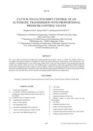
PP2 , T21 , T 1P Am& 1m& 2PS,T SP AFigure 8 Pneumatic circuit●m 1CTFIInertial massP 1P 101 AA 1 v vSFTS●m 1vP 101 RPSESM∫xSFCSF SE1Resistance ofsolenoid valve (P→A)●m 1T STSAir supplyPneumatic cylinder11RSEv P 2P2A 2v vFrictionat the pistonCTF 0A 20SF SFP 2C∫T SF SEFForce by P A1●m 2 2vMxResistance ofspeed controllerT 2RAtmosphereT 2●m 2●m 21PSEAFigure 9 Bond-graph model for pneumatic circuitFigure 10 Edit of pneumatic circuit in OHC-SimFigure 11 Simulated resultsintegrating flow m& and v. And effort P is equal in therod-end chamber of the pneumatic cylinder. Therefore,the rod-end chamber of pneumatic cylinder can berepresented as shown in Fig. 7. Then, it should be notedthat the temperature of air in the rod-end chamber isused in calculating the pressure of air in the chamber byEq. (13).SIMULATION OF DYNAMICCHARACTERISTICS OF PNEUMATIC CIRCUITBY OHC-SimIn oeder to show the usefulness of the above-mentionedbond-graph models, the simulation of the dynamiccharacteristics of the pneumatic circuit shown in Fig. 8was carried out. The bond-graph model for the circuit isshown in Fig. 9. Since the pressure and the temperatureof air at the air supply are considered to be constant, theair supply can be modeled by an SE-element. When theflow through the solenoid valve or the speed controllerlocated at the rod end of the pneumatic cylinder isassumed to be similar to that through the restrictionshown in Fig.3, each valve can be regarded as anR-element. Then, the resistance of the speed controllerincludes the resistance between B-port and T-port of thesolenoid valve. The pressure and the temperature of theatmosphere are constant. Therefore, the atmosphere canbe represented by an SE-element.The bond-graph model shown in Fig. 9 for eachpneumatic component was registered to OHC-Sim byusing the user-customized function. Figure 10 shows thepneumatic circuit constructed in OHC-Sim. To calculatethe mass flow rate through the solenoid valve or thespeed controller and the pressure at the head-end100028 sakurai 5/6
chamber of the pneumatic cylinder, the temperature atthe upstream component is necessary. Therefore, thetemperature is inputted to these components by copyand paste of the sensor sensing the temperature at the airsupply or the rod-end chamber of the pneumaticcylinder.Figure 11 shows the simulated results of the dynamiccharacteristics of the pneumatic circuit in the case wherethe P-port is connected to the A-port of the solenoidvalve at time 0.1s. As a result, it is shown that thesimulation of the dynamic characteristics of a pneumaticcircuit becomes possible on OHC-Sim by using theproposed bond-graph models.CONCLUSIONSThe bond-graph models for pneumatic components werederived, which were composed of 1-port C element and1-port R-element. Furthermore, in order to investigatethe usefulness of the proposed bond-graph models, thesemodels were registered to OHC-Sim by using theuser-customized function, and the simulation ofdynamic characteristics of a pneumatic circuit wascarried out. Consequently, it was shown that thesimulation of the dynamic characteristics of a pneumaticcircuit became possible on OHC-Sim by adopting theproposed bond-graph models without modifyingOHC-Sim. It is a great merit that the modification ofOHC-Sim is not necessary when the proposedbond-graph models are employed in the modeling ofpneumatic components. Next step will be to confirm thevalidity of the simulated results on OHC-Sim bycomparing the simulated results with the experimentalones in various pneumatic circuits.in Fluid Power Technology, MelbourneAUSTRALIA, 2003, pp.111-121.5. Rosenberg, R.C. and Karnopp, D.C., Introduction toPhysical System Dynamics, McGraw-Hill, 1983.6. Thoma, J.U., Simulation by Bondgraphs,Springer-Verlag, 1990.7. Yata, Y., Nakada, T., Sakurai, Y., Tanaka, K.,Dynamic Characteristics of Low-pressure WaterHydraulic System, Fluid Power (Proceedings of the5 th JFPS International Symposium on Fluid Power),Nara JAPAN, 2002, pp.161-166.8. Thoma, J.U. and B. Ould Bouamama, Modelling andSimulation in Thermal and Chemical Engineering,Springer, 2000.9. e.g. Kohda, T. and Nakada, T., Introduction of BondGraph Simulation Program (BGSP), Fluid Power(Proceedings of the 2 nd JHPS InternationalSymposium on Fluid Power), Tokyo JAPAN, 1993,pp.173-182.10. e.g. Sakurai, Y., Calculation of Dynamic OverallEfficiency of a Load Sensing Hydraulic System byBondgraphs, Proceeding of IEEE InternationalConference on Industrial Electronics, Control andInstrumentation, Nagoya JAPAN, 2000, pp.1568-1573.REFERENCES1. Nakada, T., Tanaka, K., Kohda, T., Sakurai, Y. andSuzuki, K., Introduction of Innovative ProgramOHC-Sim for Oil-Hydraulic Circuit Simulation,Fluid Power (Proceedings of the 3rd JHPSInternational Symposium on Fluid Power),Yokohama JAPAN, 1996, pp.679-682.2. e.g. Sakurai, Y., Kohda, T., Tanaka, K., Nakada, T.,Enhancement of OHC-Sim (Oil-Hydraulic CircuitSimulation Package), Proceedings of 4 th JHPSInternational Symposium on Fluid Power, TokyoJAPAN, 1999, pp.225-230.3. Sakurai, Y., Tanaka, K., Kohda, T., Nakada, T.,Simulation Package OHC-Sim with UserCustomized Function, Proceedings of 7 thScandinavian International Conference on FluidPower, Linköping SWEDEN, 2001, pp.127-141.4. Sakurai, Y., Tanaka, K., Nakada, T., Kohda, T.,Simulation Package OHC-Sim Ver.2.4 with UserCustomized Function, Proceedings of 1 stInternational Conference on Computational Method100028 sakurai 6/6