CHAPTER 12 THREE-PHASE CONTROLLED RECTIFIERS ∫
CHAPTER 12 THREE-PHASE CONTROLLED RECTIFIERS ∫
CHAPTER 12 THREE-PHASE CONTROLLED RECTIFIERS ∫

Create successful ePaper yourself
Turn your PDF publications into a flip-book with our unique Google optimized e-Paper software.
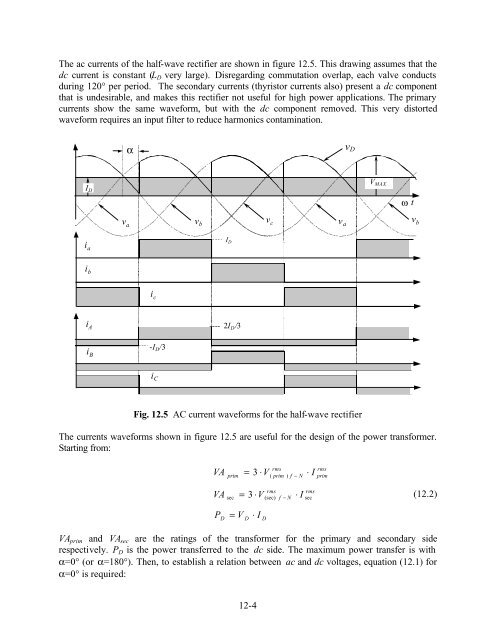
The ac currents of the half-wave rectifier are shown in figure <strong>12</strong>.5. This drawing assumes that thedc current is constant (L D very large). Disregarding commutation overlap, each valve conductsduring <strong>12</strong>0° per period. The secondary currents (thyristor currents also) present a dc componentthat is undesirable, and makes this rectifier not useful for high power applications. The primarycurrents show the same waveform, but with the dc component removed. This very distortedwaveform requires an input filter to reduce harmonics contamination.αv DI DV MAXω tv av bv cv av bi aI Di bi ci A-I D /32I D /3i Bi CFig. <strong>12</strong>.5 AC current waveforms for the half-wave rectifierThe currents waveforms shown in figure <strong>12</strong>.5 are useful for the design of the power transformer.Starting from:VAprim=3 ⋅Vrms( prim ) f − N⋅ IrmsprimVAsec=3 ⋅Vrms(sec) f − N⋅ Irmssec(<strong>12</strong>.2)PD= VD⋅ IDVA prim and VA sec are the ratings of the transformer for the primary and secondary siderespectively. P D is the power transferred to the dc side. The maximum power transfer is withα=0° (or α=180°). Then, to establish a relation between ac and dc voltages, equation (<strong>12</strong>.1) forα=0° is required:<strong>12</strong>-4