Outdoor Tube System - OTS Installation Instructions - Kim Lighting
Outdoor Tube System - OTS Installation Instructions - Kim Lighting
Outdoor Tube System - OTS Installation Instructions - Kim Lighting

Create successful ePaper yourself
Turn your PDF publications into a flip-book with our unique Google optimized e-Paper software.
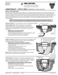
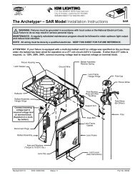
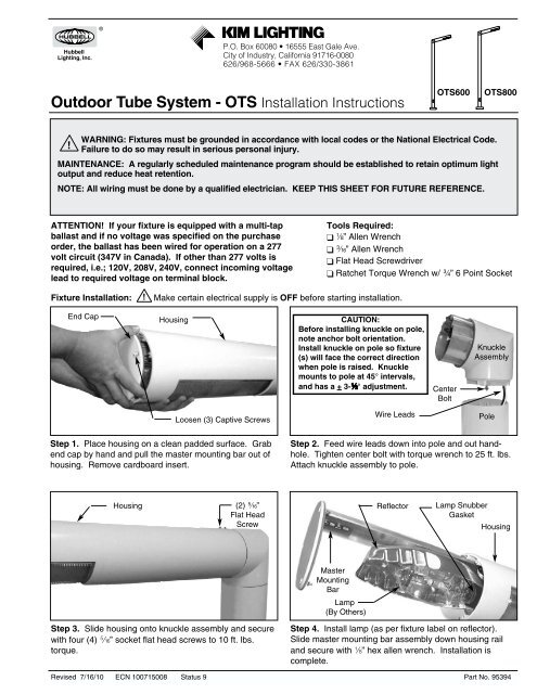
P.O. Box 60080 • 16555 East Gale Ave.City of Industry, California 91716-0080626/968-5666 • FAX 626/330-3861<strong>Outdoor</strong> <strong>Tube</strong> <strong>System</strong> - <strong>OTS</strong> <strong>Installation</strong> <strong>Instructions</strong><strong>OTS</strong>600<strong>OTS</strong>800!WARNING: Fixtures must be grounded in accordance with local codes or the National Electrical Code.Failure to do so may result in serious personal injury.MAINTENANCE: A regularly scheduled maintenance program should be established to retain optimum lightoutput and reduce heat retention.NOTE: All wiring must be done by a qualified electrician. KEEP THIS SHEET FOR FUTURE REFERENCE.ATTENTION! If your fixture is equipped with a multi-tapballast and if no voltage was specified on the purchaseorder, the ballast has been wired for operation on a 277volt circuit (347V in Canada). If other than 277 volts isrequired, i.e.; 120V, 208V, 240V, connect incoming voltagelead to required voltage on terminal block.Tools Required:B” Allen WrenchF” Allen WrenchFlat Head ScrewdriverRatchet Torque Wrench w/ L” 6 Point SocketFixture <strong>Installation</strong>:!Make certain electrical supply is OFF before starting installation.End CapHousingCAUTION:Before installing knuckle on pole,note anchor bolt orientation.Install knuckle on pole so fixture(s) will face the correct directionwhen pole is raised. Knucklemounts to pole at 45° intervals,and has a + 3-K° adjustment.CenterBoltKnuckleAssemblyLoosen (3) Captive ScrewsWire LeadsPoleStep 1. Place housing on a clean padded surface. Grabend cap by hand and pull the master mounting bar out ofhousing. Remove cardboard insert.Step 2. Feed wire leads down into pole and out handhole.Tighten center bolt with torque wrench to 25 ft. lbs.Attach knuckle assembly to pole.Housing(2) M”Flat HeadScrewReflectorLamp SnubberGasketHousingMasterMountingBarLamp(By Others)Step 3. Slide housing onto knuckle assembly and securewith four (4) M” socket flat head screws to 10 ft. lbs.torque.Step 4. Install lamp (as per fixture label on reflector).Slide master mounting bar assembly down housing railand secure with B” hex allen wrench. <strong>Installation</strong> iscomplete.Revised 7/16/10 ECN 100715008 Status 9 Part No. 95394
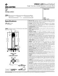
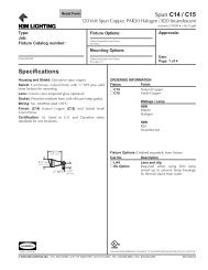
<strong>OTS</strong>600 / <strong>OTS</strong>800 <strong>Installation</strong> <strong>Instructions</strong>BALLAST INSTALLATION: ! Make certain electrical supply is OFF before starting ballast installation.Step 1. Make sure new ballast assembly is correct. Check line voltage, lamp type and wattage.End CapMountingBarHousingLamp CircuitConnectorsTerminalBlockPowerDisconnectGuideBallast AssemblyStep 2. Grab end cap by hand and pull the mastermounting bar out of housing. Place on padded surface.Master Mountng BarLamp of Type(By Others)Step 4. Install lamp (as per fixture label on reflector).Slide master mounting bar assembly down housing railand secure with B” hex allen wrench.Step 3. Disconnect lamp and ballast wire connections.Remove old ballast by loosening screws at keyhole (donot remove screws). Slide out ballast assembly. Slidein new ballast assembly and secure. Connect lamp andballast wire connectors.LAMP INSTALLATION: ! Make certain electricalsupply is OFF before starting lamp installation.Step 1. Make sure new lamp is correct, (as per fixturelabel on reflector). Check lamp wattage and type.Step 2. Follow Step 2 in Ballast <strong>Installation</strong> <strong>Instructions</strong>.Step 3. Screw lamp into socket, tighten sufficiently toensure a vibration safe installation.Step 4. Slide master mounting bar assembly downhousing rail and secure with B" hex allen wrench.CAUTION: The H.I.D. / Fluorescent fixture utilizes a lampthat may contain mercury. For information on disposal oflamp, go to website: www.lamprecycle.orgMAINTENANCE INSTRUCTIONSLENS REPLACEMENT: ! Make certain fixture is turned OFF before starting maintenance.Step 1. For opening and closing of the fixture refer to Fixture <strong>Installation</strong>, steps 1 & 4 on page 1.Step 2. Reach in and remove the lens clip then remove the glass lens with its gasket around the flange.Step 3. Hold new lens with both hands and make sure gasket is fully seated all around the flange. One end of thelens is marked “Street End”.Step 4. Insert pole end of the lens at a 45° angle into the housing, and swing street end of glass towards the housinguntil top flange of glass is seated on edge of housing. Hold the glass in this position and slide it B” towards street endof housing. While holding the lens with one hand, reach into the housing and mount the street end bracket (thebracket with hole) by fully tightening the screw so that the bracket is hooked in the provided notch on glass. Mount thepole end bracket (the bracket slot) the same way.Important: A regularly scheduled maintenance programshould be followed to retain optimum light output andreduce heat retention. Dusting with a soft, clean, dry clothis normally sufficient for the reflector. Any accumulation ofdust or dirt should be removed regularly from both sides ofthe lens using ammonia water. Do not use alkaline or acidcleaners on reflector surface.Page 2 <strong>Kim</strong> <strong>Lighting</strong> • 16555 E. Gale Ave. • P.O. Box 60080 • City of Industry, CA 91716-0080 • 626/968-5666 • FAX 626/330-3861
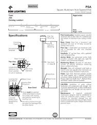
<strong>OTS</strong>600 / <strong>OTS</strong>800 <strong>Installation</strong> <strong>Instructions</strong>Optional LG600 and LG800Lens Guard Mounting Instruction:Tool Required:❑ Phillips Head ScrewdriverSecure With ScrewsProvided (4)Align Lens Guard WithTapped Holes In Housing.KIM LIGHTING LIMITED WARRANTYWhen installed in accordance with <strong>Kim</strong> <strong>Installation</strong> <strong>Instructions</strong> and accepted trade practices, the followingshall apply:General Product Limited Warranty CoverageAll material and component parts used in the manufacture of <strong>Kim</strong> Products, are warranted to be free fromdefects of material and/or workmanship for a period of 1 year from date of sale, with the following exceptions:Auxiliary EquipmentAll auxiliary equipment (such as lamps, ballasts, and transformers) provided by and/or included in <strong>Kim</strong>Products shall carry the component manufacturer's warranty.Copper and Bronze Landscape ComponentsCopper and Bronze Landscape fixture components shall be warranted against defects of material and/orworkmanship, and failure due to corrosion, for a period of 25 years from date of sale.Composite In-Grade ComponentsComposite In-Grade fixture components shall be warranted against defects of material and/or workmanship,and failure due to corrosion, for a period of 7 years from date of sale.Aluminum Landscape ComponentsAluminum Landscape fixture components not in direct contact with soil, shall be warranted against defects ofmaterial and/or workmanship for a period of 3 years from date of sale. Aluminum fixture components in directcontact with soil shall be warranted from defects of material and failure from corrosion for a period of 1 yearfrom date of sale.Limit of Liability and General ConditionsOnly products which are installed, used and maintained in accordance with applicable <strong>Kim</strong> instructions,specifications and accepted trade practices, are covered by the <strong>Kim</strong> Warranty. During the warranty period,with proof of purchase, <strong>Kim</strong> will repair or replace with the same or similar product, at <strong>Kim</strong> 's option, withoutcharge. Labor costs are the owner's responsibility and are excluded from this warranty. This warranty is void ifthe product is modified, tampered with, misapplied, poorly installed, improperly maintained, or subjected toabnormal conditions.Repair or replacement as provided under this warranty is the exclusive remedy of the purchaser. This warrantyis in lieu of all other warranties, expressed or implied, including any implied warranty of fitness for a particularapplication. <strong>Kim</strong> <strong>Lighting</strong> shall not be liable to the purchaser for indirect or consequential damages.How may we serve you better?Please let us know. Visit our website at:www.kimlighting.comYour concerns matter to us.Page 3 <strong>Kim</strong> <strong>Lighting</strong> • 16555 E. Gale Ave. • P.O. Box 60080 • City of Industry, CA 91716-0080 • 626/968-5666 • FAX 626/330-3861