Rapid Visual Screening of Buildings for Potential Seismic Hazards
Rapid Visual Screening of Buildings for Potential Seismic Hazards
Rapid Visual Screening of Buildings for Potential Seismic Hazards

You also want an ePaper? Increase the reach of your titles
YUMPU automatically turns print PDFs into web optimized ePapers that Google loves.
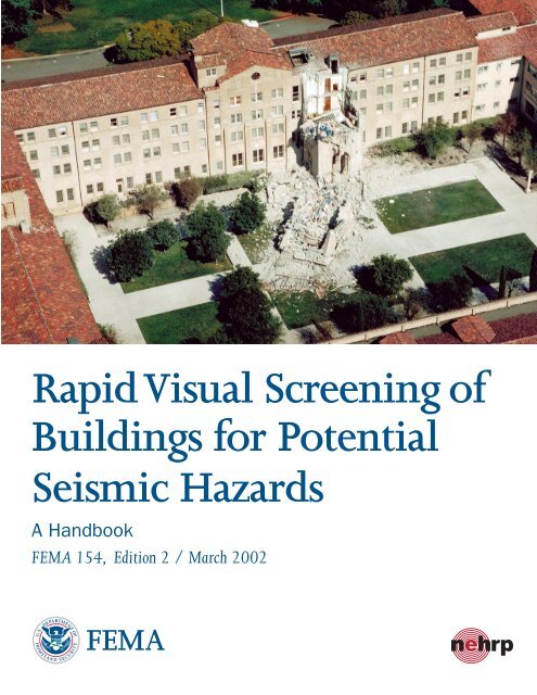
<strong>Rapid</strong> <strong>Visual</strong> <strong>Screening</strong> <strong>of</strong><strong>Buildings</strong> <strong>for</strong> <strong>Potential</strong><strong>Seismic</strong> <strong>Hazards</strong>A HandbookFEMA 154, Edition 2 / March 2002FEMA
NATIONAL EARTHQUAKE HAZARDS REDUCTION PROGRAMSecond EditionRAPID VISUAL SCREENING OF BUILDINGSFOR POTENTIAL SEISMIC HAZARDS:A HANDBOOKAPPLIED TECHNOLOGY COUNCIL555 Twin Dolphin Drive, Suite 550Redwood City, Cali<strong>for</strong>nia 94065Funded byFEMAWashington, DC
FEMA ForewordThe Federal Emergency Management Agency(FEMA) is pleased to present the second edition <strong>of</strong>the widely used <strong>Rapid</strong> <strong>Visual</strong> <strong>Screening</strong> <strong>of</strong><strong>Buildings</strong> <strong>for</strong> <strong>Potential</strong> <strong>Seismic</strong> <strong>Hazards</strong>: AHandbook, and its companion, SupportingDocumentation. The policy <strong>of</strong> improving reportsand manuals that deal with the seismic safety <strong>of</strong>existing buildings as soon as new in<strong>for</strong>mation andadequate resources are available is thus beingreaffirmed. Users should take note <strong>of</strong> some majordifferences between the two editions <strong>of</strong> theHandbook. The technical content <strong>of</strong> the newedition is based more on experiential data and lesson expert judgment than was the case in the earlieredition, as is explained in the SupportingDocumentation. From the presentational point <strong>of</strong>view, the Handbook retains much <strong>of</strong> the material<strong>of</strong> the earlier edition, but the material has beenrather thoroughly rearranged to further facilitatethe step-by-step process <strong>of</strong> conducting the rapidvisual screening <strong>of</strong> a building. By far the mostsignificant difference between the two editions,however, is the need <strong>for</strong> a higher level <strong>of</strong>engineering understanding and expertise on thepart <strong>of</strong> the users <strong>of</strong> the second edition. This shifthas been caused primarily by the difficultyexperienced by users <strong>of</strong> the first edition inidentifying the lateral-<strong>for</strong>ce-resisting system <strong>of</strong> abuilding without entry—a critical decision <strong>of</strong> therapid visual screening process. The contents <strong>of</strong>the Supporting Documentation volume have alsobeen enriched to reflect the technical advances inthe Handbook.FEMA and the Project Officer wish to expresstheir gratitude to the members <strong>of</strong> the ProjectAdvisory Panel, to the technical and workshopconsultants, to the project management, and to thereport production and editing staff <strong>for</strong> theirexpertise and dedication in the upgrading <strong>of</strong> thesetwo volumes.The Federal Emergency Management AgencyFEMA 154 FEMA Foreword iii
PrefaceIn August 1999 the Federal EmergencyManagement Agency (FEMA) awarded theApplied Technology Council (ATC) a two-yearcontract to update the FEMA 154 report, <strong>Rapid</strong><strong>Visual</strong> <strong>Screening</strong> <strong>of</strong> <strong>Buildings</strong> <strong>for</strong> <strong>Potential</strong><strong>Seismic</strong> <strong>Hazards</strong>: A Handbook, and thecompanion FEMA-155 report, <strong>Rapid</strong> <strong>Visual</strong><strong>Screening</strong> <strong>of</strong> <strong>Buildings</strong> <strong>for</strong> <strong>Potential</strong> <strong>Seismic</strong><strong>Hazards</strong>: Supporting Documentation, both <strong>of</strong>which were originally published in 1988.The impetus <strong>for</strong> the project stemmed in partfrom the general recommendation in the FEMA315 report, <strong>Seismic</strong> Rehabilitation <strong>of</strong> <strong>Buildings</strong>:Strategic Plan 2005, to update periodically allexisting reports in the FEMA-developed series onthe seismic evaluation and rehabilitation <strong>of</strong>existing buildings. In addition, a vast amount <strong>of</strong>in<strong>for</strong>mation had been developed since 1988,including: (1) new knowledge about theper<strong>for</strong>mance <strong>of</strong> buildings during damagingearthquakes, including the 1989 Loma Prieta and1994 Northridge earthquakes; (2) new knowledgeabout seismic hazards, including updated nationalseismic hazard maps published by the U. S.Geological Survey in 1996; (3) other new seismicevaluation and damage prediction tools, such asthe FEMA 310 report, Handbook <strong>for</strong> the <strong>Seismic</strong>Evaluation <strong>of</strong> <strong>Buildings</strong> – a Prestandard, (anupdated version <strong>of</strong> FEMA 178, NEHRP Handbook<strong>for</strong> the <strong>Seismic</strong> Evaluation <strong>of</strong> Existing <strong>Buildings</strong>),and HAZUS, FEMA’s tool <strong>for</strong> estimating potentiallosses from natural disasters; and (4) experiencefrom the widespread use <strong>of</strong> the original FEMA154 Handbook by federal, state and municipalagencies, and others.The project included the following tasks:(1) an ef<strong>for</strong>t to obtain users feedback, which wasexecuted through the distribution <strong>of</strong> a voluntaryFEMA 154 Users Feedback Form to organizationsthat had ordered or were known to have usedFEMA 154 (the Feedback Form was also postedon ATC’s web site); (2) a review <strong>of</strong> availablein<strong>for</strong>mation on the seismic per<strong>for</strong>mance <strong>of</strong>buildings, including a detailed review <strong>of</strong> theHAZUS fragility curves and an ef<strong>for</strong>t to correlatethe relationship between results from the use <strong>of</strong>both the FEMA 154 rapid visual screeningprocedure and the FEMA 178 detailed seismicevaluation procedures on the same buildings;(3) a Users Workshop midway in the project tolearn first hand the problems and successes <strong>of</strong>organizations that had used the rapid visualscreening procedure on buildings under theirjurisdiction; (4) updating <strong>of</strong> the original FEMA154 Handbook to create the second edition; and(5) updating <strong>of</strong> the original FEMA 155 SupportingDocumentation report to create the second edition.This second edition <strong>of</strong> the FEMA 154Handbook provides a standard rapid visualscreening procedure to identify, inventory, andrank buildings that are potentially seismicallyhazardous. The scoring system has been revised,based on new in<strong>for</strong>mation, and the Handbook hasbeen shortened and focused to facilitateimplementation. The technical basis <strong>for</strong> the rapidvisual screening procedure, including a summary<strong>of</strong> results from the ef<strong>for</strong>ts to solicit user feedback,is documented in the companion second edition <strong>of</strong>the FEMA 155 report, <strong>Rapid</strong> <strong>Visual</strong> <strong>Screening</strong> <strong>of</strong><strong>Buildings</strong> <strong>for</strong> <strong>Potential</strong> <strong>Seismic</strong> <strong>Hazards</strong>:Supporting Documentation.ATC gratefully acknowledges the personnelinvolved in developing the second editions <strong>of</strong> theFEMA 154 and FEMA 155 reports. CharlesScawthorn served as Co-Principal Investigator andProject Director. He was assisted by Kent David,Vincent Prabis, Richard A. Ranous, and NileshShome, who served as Technical Consultants.Members <strong>of</strong> the Project Advisory Panel, whoprovided overall review and guidance <strong>for</strong> theproject, were: Thalia Anagnos, John Baals, JamesR. Cagley (ATC Board Representative), MelvynGreen, Terry Hughes, Anne S. Kiremidjian, JoanMacQuarrie, Chris D. Poland, Lawrence D.Reaveley, Doug Smits, and Ted Winstead.William T. Holmes served as facilitator <strong>for</strong> theUsers Workshop, and Keith Porter served asrecorder. Stephanie A. King verified the BasicStructural Hazard Scores and the Score Modifiers.A. Gerald Brady, Peter N. Mork, and MichelleSchwartzbach provided report editing andproduction services. The affiliations <strong>of</strong> theseindividuals are provided in the list <strong>of</strong> projectparticipants.ATC also gratefully acknowledges thevaluable assistance, support, and cooperationprovided by Ugo Morelli, FEMA Project Officer.In addition, ATC acknowledges participants in theFEMA 154 Preface v
FEMA 154 Users Workshop, which included, inaddition to the project personnel listed above, thefollowing individuals: Al Berstein, U. S. Bureau<strong>of</strong> Reclamation; Amitabha Datta, General ServicesAdministration; Ben Emam, Amazon.com;Richard K. Eisner, Cali<strong>for</strong>nia Office <strong>of</strong> EmergencyServices; Ali Fattah, City <strong>of</strong> San Diego; BrianKehoe, Wiss Janney Elstner Associates, Inc.;David Leung, City and County <strong>of</strong> San Francisco;Douglas McCall, Marx/Okubo; Richard Silva,National Park Service; Howard Simpson, SimpsonGumpertz & Heger Inc.; Steven Sweeney, U. S.Army Civil Engineering Research Laboratory;Christine Theodooropoulos, University <strong>of</strong> Oregon;and Zan Turner, City and County <strong>of</strong> SanFrancisco. Those persons who responded toATC’s request to complete the voluntary FEMA154 Users Feedback <strong>for</strong>m are also gratefullyacknowledged.Christopher Rojahn, Principal InvestigatorATC Executive Directorvi Preface FEMA 154
Summary and ApplicationThis FEMA 154 Report, <strong>Rapid</strong> <strong>Visual</strong> <strong>Screening</strong><strong>of</strong> <strong>Buildings</strong> <strong>for</strong> <strong>Potential</strong> <strong>Seismic</strong> <strong>Hazards</strong>: AHandbook, is the first <strong>of</strong> a two-volume publicationon a recommended methodology <strong>for</strong> rapid visualscreening <strong>of</strong> buildings <strong>for</strong> potential seismichazards. The technical basis <strong>for</strong> the methodology,including the scoring system and its development,are contained in the companion FEMA 155 report,<strong>Rapid</strong> <strong>Visual</strong> <strong>Screening</strong> <strong>of</strong> <strong>Buildings</strong> <strong>for</strong> <strong>Potential</strong><strong>Seismic</strong> <strong>Hazards</strong>: Supporting Documentation.Both this document and the companion documentare second editions <strong>of</strong> similar documentspublished by FEMA in 1988.The rapid visual screening procedure (RVS)has been developed <strong>for</strong> a broad audience,including building <strong>of</strong>ficials and inspectors, andgovernment agency and private-sector buildingowners (hereinafter, the "RVS authority"), toidentify, inventory, and rank buildings that arepotentially seismically hazardous. Although RVSis applicable to all buildings, its principal purposeis to identify (1) older buildings designed andconstructed be<strong>for</strong>e the adoption <strong>of</strong> adequateseismic design and detailing requirements, (2)buildings on s<strong>of</strong>t or poor soils, or (3) buildingshaving per<strong>for</strong>mance characteristics that negativelyinfluence their seismic response. Once identifiedas potentially hazardous, such buildings should befurther evaluated by a design pr<strong>of</strong>essionalexperienced in seismic design to determine if, infact, they are seismically hazardous.The RVS uses a methodology based on a“sidewalk survey” <strong>of</strong> a building and a DataCollection Form, which the person conducting thesurvey (hereafter referred to as the screener)completes, based on visual observation <strong>of</strong> thebuilding from the exterior, and if possible, theinterior. The Data Collection Form includes space<strong>for</strong> documenting building identificationin<strong>for</strong>mation, including its use and size, aphotograph <strong>of</strong> the building, sketches, anddocumentation <strong>of</strong> pertinent data related to seismicper<strong>for</strong>mance, including the development <strong>of</strong> anumeric seismic hazard score.Once the decision to conduct rapid visualscreening <strong>for</strong> a community or group <strong>of</strong> buildingshas been made by the RVS authority, thescreening ef<strong>for</strong>t can be expedited by pre-planning,including the training <strong>of</strong> screeners, and carefuloverall management <strong>of</strong> the process.Completion <strong>of</strong> the Data Collection Form in thefield begins with identifying the primary structurallateral-load-resisting system and structuralmaterials <strong>of</strong> the building. Basic Structural HazardScores <strong>for</strong> various building types are provided onthe <strong>for</strong>m, and the screener circles the appropriateone. For many buildings, viewed only from theexterior, this important decision requires thescreener to be trained and experienced in buildingconstruction. The screener modifies the BasicStructural Hazard Score by identifying andcircling Score Modifiers, which are related toobserved per<strong>for</strong>mance attributes, and which arethen added (or subtracted) to the Basic StructuralHazard Score to arrive at a final Structural Score,S. The Basic Structural Hazard Score, ScoreModifiers, and final Structural Score, S, all relateto the probability <strong>of</strong> building collapse, shouldsevere ground shaking occur (that is, a groundshaking level equivalent to that currently used inthe seismic design <strong>of</strong> new buildings). Final Sscores typically range from 0 to 7, with higher Sscores corresponding to better expected seismicper<strong>for</strong>mance.Use <strong>of</strong> the RVS on a community-wide basisenables the RVS authority to divide screenedbuildings into two categories: those that areexpected to have acceptable seismic per<strong>for</strong>mance,and those that may be seismically hazardous andshould be studied further. An S score <strong>of</strong> 2 issuggested as a “cut-<strong>of</strong>f”, based on present seismicdesign criteria. Using this cut-<strong>of</strong>f level, buildingshaving an S score <strong>of</strong> 2 or less should beinvestigated by a design pr<strong>of</strong>essional experiencedin seismic design.The procedure presented in this Handbook ismeant to be the preliminary screening phase <strong>of</strong> amulti-phase procedure <strong>for</strong> identifying potentiallyhazardous buildings. <strong>Buildings</strong> identified by thisprocedure must be analyzed in more detail by anexperienced seismic design pr<strong>of</strong>essional. Becauserapid visual screening is designed to be per<strong>for</strong>medfrom the street, with interior inspection not alwayspossible, hazardous details will not always bevisible, and seismically hazardous buildings maynot be identified as such. Conversely, buildingsinitially identified as potentially hazardous byRVS may prove to be adequate.FEMA 154 Summary and Application vii
ContentsFEMA Foreword................................................................................................................................................ iiiPreface .................................................................................................................................................................vSummary and Application ................................................................................................................................ viiList <strong>of</strong> Figures.................................................................................................................................................. xiiiList <strong>of</strong> Tables ....................................................................................................................................................xixIllustration Credits ............................................................................................................................................xxi1. Introduction ...................................................................................................................................................11.1 Background..........................................................................................................................................11.2 <strong>Screening</strong> Procedure Purpose, Overview, and Scope..........................................................................21.3 Companion FEMA 155 Report............................................................................................................31.4 Relationship <strong>of</strong> FEMA 154 to Other Documents in the FEMA Existing Building Series ..................41.5 Uses <strong>of</strong> RVS Survey Results ...............................................................................................................41.6 How to Use this Handbook..................................................................................................................42. Planning and Managing <strong>Rapid</strong> <strong>Visual</strong> <strong>Screening</strong>..........................................................................................52.1 <strong>Screening</strong> Implementation Sequence...................................................................................................52.2 Budget Development and Cost Estimation..........................................................................................62.3 Pre-Field Planning ...............................................................................................................................62.4 Selection and Review <strong>of</strong> the Data Collection Form ............................................................................72.4.1 Determination <strong>of</strong> <strong>Seismic</strong>ity Region ......................................................................................82.4.2 Determination <strong>of</strong> Key <strong>Seismic</strong> Code Adoption Dates and Other Considerations ..................82.4.3 Determination <strong>of</strong> Cut-Off Score ...........................................................................................102.5 Qualifications and Training <strong>for</strong> Screeners.........................................................................................112.6 Acquisition and Review <strong>of</strong> Pre-Field Data........................................................................................112.6.1 Assessor’s Files ....................................................................................................................112.6.2 Building Department Files....................................................................................................122.6.3 Sanborn Maps.......................................................................................................................122.6.4 Municipal Databases.............................................................................................................152.6.5 Previous Studies ...................................................................................................................152.6.6 Soils In<strong>for</strong>mation ..................................................................................................................152.7 Review <strong>of</strong> Construction Documents..................................................................................................172.8 Field <strong>Screening</strong> <strong>of</strong> <strong>Buildings</strong> .............................................................................................................182.9 Checking the Quality and Filing the Field Data in the Record-Keeping System ..............................183. Completing the Data Collection Form ........................................................................................................193.1 Introduction .......................................................................................................................................193.2 Verifying and Updating the Building Identification In<strong>for</strong>mation......................................................203.2.1 Number <strong>of</strong> Stories.................................................................................................................203.2.2 Year Built .............................................................................................................................203.2.3 Screener Identification..........................................................................................................203.2.4 Total Floor Area ...................................................................................................................213.3 Sketching the Plan and Elevation Views ...........................................................................................213.4 Determining Soil Type ......................................................................................................................213.5 Determining and Documenting Occupancy.......................................................................................223.5.1 Occupancy ............................................................................................................................223.5.2 Occupancy Load...................................................................................................................23FEMA 154 Contents ix
3.6 Identifying <strong>Potential</strong> Nonstructural Falling <strong>Hazards</strong>.........................................................................233.7 Identifying the Lateral-Load-Resisting System and Documenting the Related BasicStructural Score .................................................................................................................................243.7.1 Fifteen Building Types Considered by the RVS Procedure and Related BasicStructural Scores...................................................................................................................243.7.2 Identifying the Lateral-Force-Resisting System...................................................................253.7.3 Interior Inspections...............................................................................................................363.7.4 <strong>Screening</strong> <strong>Buildings</strong> with More Than One Lateral-Force Resisting System........................373.8 Identifying <strong>Seismic</strong> Per<strong>for</strong>mance Attributes and Recording Score Modifiers ..................................383.8.1 Mid-Rise <strong>Buildings</strong>...............................................................................................................383.8.2 High-Rise <strong>Buildings</strong> .............................................................................................................383.8.3 Vertical Irregularity ..............................................................................................................383.8.4 Plan Irregularity....................................................................................................................403.8.5 Pre-Code ...............................................................................................................................403.8.6 Post-Benchmark....................................................................................................................413.8.7 Soil Type C, D, or E .............................................................................................................413.9 Determining the Final Score..............................................................................................................413.10 Photographing the Building...............................................................................................................423.11 Comments Section.............................................................................................................................424. Using the RVS Procedure Results...............................................................................................................434.1 Interpretation <strong>of</strong> RVS Score ..............................................................................................................434.2 Selection <strong>of</strong> RVS “Cut-Off” Score....................................................................................................434.3 Prior Uses <strong>of</strong> the RVS Procedure ......................................................................................................444.4 Other Possible Uses <strong>of</strong> the RVS Procedure.......................................................................................454.4.1 Using RVS Scores as a Basis <strong>for</strong> Hazardous Building Mitigation Programs.......................454.4.2 Using RVS Data in Community Building Inventory Development .....................................464.4.3 Using RVS Data to Plan Postearthquake Building-Safety-Evaluation Ef<strong>for</strong>ts.....................464.4.4 Resources Needed <strong>for</strong> the Various Uses <strong>of</strong> the RVS Procedure...........................................465. Example Application <strong>of</strong> <strong>Rapid</strong> <strong>Visual</strong> <strong>Screening</strong>........................................................................................495.1 Step 1: Budget and Cost Estimation .................................................................................................495.2 Step 2: Pre-Field Planning................................................................................................................505.3 Step 3: Selection and Review <strong>of</strong> the Data Collection Form .............................................................505.4 Step 4: Qualifications and Training <strong>for</strong> Screeners............................................................................515.5 Step 5: Acquisition and Review <strong>of</strong> Pre-Field Data...........................................................................515.6 Step 6: Review <strong>of</strong> Construction Documents.....................................................................................555.7 Step 7: Field <strong>Screening</strong> <strong>of</strong> <strong>Buildings</strong>................................................................................................555.8 Step 8: Transferring the RVS Field Data to the Electronic Building RVS Database .......................64Appendix A: Maps Showing <strong>Seismic</strong>ity Regions.............................................................................................65Appendix B: Data Collection Forms and Quick Reference Guide ...................................................................77Appendix C: Review <strong>of</strong> Design and Construction Drawings ...........................................................................83Appendix D: Exterior <strong>Screening</strong> <strong>for</strong> <strong>Seismic</strong> System and Age ........................................................................85D.1 Introduction .......................................................................................................................................85D.2 What to Look <strong>for</strong> and How to Find It................................................................................................85D.3 Identification <strong>of</strong> Building Age...........................................................................................................85D.4 Identification <strong>of</strong> Structural Type .......................................................................................................88D.5 Characteristics <strong>of</strong> Exposed Construction Materials...........................................................................95Appendix E: Characteristics and Earthquake Per<strong>for</strong>mance <strong>of</strong> RVS Building Types........................................99E.1 Introduction .......................................................................................................................................99E.2 Wood Frame (W1, W2) .....................................................................................................................99x Contents FEMA 154
E.2.1 Characteristics ......................................................................................................................99E.2.2 Typical Earthquake Damage ..............................................................................................100E.2.3 Common Rehabilitation Techniques ..................................................................................102E.3 Steel Frames (S1, S2) ......................................................................................................................103E.3.1 Characteristics ....................................................................................................................103E.3.2 Typical Earthquake Damage ..............................................................................................105E.3.3 Common Rehabilitation Techniques ..................................................................................105E.4 Light Metal (S3) ..............................................................................................................................106E.4.1 Characteristics ....................................................................................................................106E.4.2 Typical Earthquake Damage ..............................................................................................107E.5 Steel Frame with Concrete Shear Wall (S4)....................................................................................107E.5.1 Characteristics ....................................................................................................................107E.5.2 Typical Earthquake Damage ..............................................................................................108E.6 Steel Frame with Unrein<strong>for</strong>ced Masonry Infill (S5)........................................................................108E.6.1 Characteristics ....................................................................................................................108E.6.2 Typical Earthquake Damage ..............................................................................................109E.6.3 Common Rehabilitation Techniques ..................................................................................110E.7 Concrete Moment-Resisting Frame (C1).........................................................................................110E.7.1 Characteristics ....................................................................................................................110E.7.2 Typical Earthquake Damage ..............................................................................................112E.7.3 Common Rehabilitation Techniques ..................................................................................113E.8 Concrete Shear Wall (C2)................................................................................................................113E.8.1 Characteristics ....................................................................................................................113E.8.2 Typical Types <strong>of</strong> Earthquake Damage ...............................................................................114E.8.3 Common Rehabilitation......................................................................................................114E.9 Concrete Frame with Unrein<strong>for</strong>ced Masonry Infill (C3).................................................................114E.9.1 Characteristics ....................................................................................................................114E.9.2 Typical Earthquake Damage ..............................................................................................116E.9.3 Common Rehabilitation Techniques ..................................................................................116E.10 Tilt-up Structures (PC1) ..................................................................................................................116E.10.1 Characteristics ....................................................................................................................116E.10.2 Typical Earthquake Damage ..............................................................................................117E.10.3 Common Rehabilitation Techniques ..................................................................................118E.11 Precast Concrete Frame (PC2).........................................................................................................118E.11.1 Characteristics ....................................................................................................................118E.11.2 Typical Earthquake Damage ..............................................................................................120E.11.3 Common Rehabilitation Techniques ..................................................................................120E.12 Rein<strong>for</strong>ced Masonry (RM1 and RM2) ............................................................................................121E.12.1 Characteristics ....................................................................................................................121E.12.2 Typical Earthquake Damage ..............................................................................................121E.12.3 Common Rehabilitation Techniques ..................................................................................121E.13 Unrein<strong>for</strong>ced Masonry (URM)........................................................................................................122E.13.1 Characteristics ....................................................................................................................122E.13.2 Typical Earthquake Damage ..............................................................................................126E.13.3 Common Rehabilitation Techniques ..................................................................................126Appendix F: Earthquakes and How <strong>Buildings</strong> Resist Them...........................................................................129F.1 The Nature <strong>of</strong> Earthquakes ..............................................................................................................129F.2 <strong>Seismic</strong>ity <strong>of</strong> the United States........................................................................................................130F.3 Earthquake Effects...........................................................................................................................131F.4 How <strong>Buildings</strong> Resist Earthquakes .................................................................................................134References........................................................................................................................................................137Project Participants ..........................................................................................................................................139FEMA 154 Contents xi
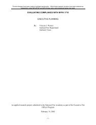
List <strong>of</strong> FiguresFigure 1-1Figure 1-2High, moderate, and low seismicity regions <strong>of</strong> the conterminous United States. Adifferent RVS Data Collection Form has been developed <strong>for</strong> each <strong>of</strong> these regions.................1Data Collection Forms <strong>for</strong> the three designated seismicity regions (low, moderate,and high). ...................................................................................................................................3Figure 2-1 <strong>Rapid</strong> visual screening implementation sequence. ....................................................................5Figure 2-2Figure 2-3Figure 2-4Example RVS Data Collection Form (high seismicity).............................................................7Sections 1 and 2 <strong>of</strong> Quick Reference Guide (<strong>for</strong> use with Data Collection Form)..................10Building identification portion <strong>of</strong> RVS Data Collection Form................................................11Figure 2-5 Example Sanborn map showing building in<strong>for</strong>mation <strong>for</strong> a city block. ..................................12Figure 2-6 Key to Sanborn map symbols. ...............................................................................................13Figure 2-7Sanborn map and corresponding aerial photograph <strong>of</strong> a city block.........................................14Figure 2-8 Photographs <strong>of</strong> elevation views <strong>of</strong> buildings shown in Figure 2-7..........................................15Figure 2-9Figure 2-10Figure 3-1Examples <strong>of</strong> in-house screen displays <strong>of</strong> municipal databases................................................16Location on Data Collection Form where soil type in<strong>for</strong>mation is recorded...........................17Example RVS Data Collection Form (high seismicity)...........................................................19Figure 3-2 Portion <strong>of</strong> Data Collection Form <strong>for</strong> documenting building identification. ............................20Figure 3-3Figure 3-4Figure 3-5Sample Data Collection Form showing location <strong>for</strong> sketches <strong>of</strong> building plan andelevation views. .......................................................................................................................21Location on Data Collection Form where soil type in<strong>for</strong>mation is documented (circled).......21Occupancy portion <strong>of</strong> Data Collection Form...........................................................................22Figure 3-6 Portion <strong>of</strong> Data Collection Form <strong>for</strong> documenting nonstructural falling hazards. ..................23Figure 3-7 Portion <strong>of</strong> Data Collection Form containing Basic Structural Hazard Scores. ........................25Figure 3-8Figure 3-9Typical frame structure. Features include: large window spans, window openings onmany sides, and clearly visible column-beam grid pattern......................................................35Typical bearing wall structure. Features include small window span, at least twomostly solid walls, and thick load-bearing walls. ....................................................................35Figure 3-10 Frame and bearing wall structures ...........................................................................................36Figure 3-11Interior view showing firepro<strong>of</strong>ed columns and beams, which indicate a steel building(S1, S2, or S4)..........................................................................................................................37FEMA 154 List <strong>of</strong> Figures xiii
Figure 3-12Figure 3-13Figure 3-14Interior view showing concrete columns and girders, which indicate a concrete momentframe (C1). .............................................................................................................................. 37Portion <strong>of</strong> Data Collection Form containing attributes that modify per<strong>for</strong>mance andassociated score modifiers....................................................................................................... 38Elevation views showing vertical irregularities, with arrows indicating locations<strong>of</strong> particular concern................................................................................................................ 39Figure 3-15 Example <strong>of</strong> setbacks and a s<strong>of</strong>t first story ............................................................................... 39Figure 3-16Figure 3-17Example <strong>of</strong> s<strong>of</strong>t story conditions, where parking requirements result in largeweak openings. ........................................................................................................................ 40Plan views <strong>of</strong> various building configurations showing plan irregularities; arrowsindicate possible areas <strong>of</strong> damage. .......................................................................................... 40Figure 3-18 Example <strong>of</strong> a building, with a plan irregularity, with two wings meeting at right angles....... 41Figure 3-19 Example <strong>of</strong> a building, triangular in plan, subject to torsion. ................................................. 41Figure 3-20Figure 5-1Location on Data Collection Form where the final score, comments, and an indicationif the building needs detailed evaluation are documented....................................................... 42Screen capture <strong>of</strong> USGS web page showing SA values <strong>for</strong> 0.2 sec and 1.0 sec <strong>for</strong> groundmotions having 2% probability <strong>of</strong> being exceeded in 50 years............................................... 50Figure 5-2 High seismicity Data Collection Form selected <strong>for</strong> Anyplace, USA ...................................... 52Figure 5-3Quick Reference Guide <strong>for</strong> Anyplace USA showing entries <strong>for</strong> years in which seismiccodes were first adopted and en<strong>for</strong>ced and benchmark years. ................................................ 53Figure 5-4 Property in<strong>for</strong>mation at example site in city’s geographic in<strong>for</strong>mation system...................... 54Figure 5-5 Exterior view <strong>of</strong> 3703 Roxbury Street .................................................................................... 56Figure 5-6 Close-up view <strong>of</strong> 3703 Roxbury Street exterior showing perimeter braced steel framing...... 56Figure 5-7 Building identification portion <strong>of</strong> Data Collection Form <strong>for</strong> Example 1,3703 Roxbury Street................................................................................................................ 56Figure 5-8 Completed Data Collection Form <strong>for</strong> Example 1, 3703 Roxbury Street................................. 57Figure 5-9 Exterior view <strong>of</strong> 3711 Roxbury............................................................................................... 58Figure 5-10Close-up view <strong>of</strong> 3711 Roxbury Street building exterior showing infillframe construction................................................................................................................... 58Figure 5-11 Completed Data Collection Form <strong>for</strong> Example 2, 3711 Roxbury Street................................. 59Figure 5-12 Exterior view <strong>of</strong> 5020 Ebony Drive ........................................................................................ 60Figure 5-13 Completed Data Collection Form <strong>for</strong> Example 3, 5020 Ebony Drive .................................... 61Figure 5-14 Exterior view <strong>of</strong> 1450 Addison Avenue.................................................................................. 62xiv List <strong>of</strong> Figures FEMA 154
Figure 5-15Building identification portion <strong>of</strong> Data Collection Form <strong>for</strong> Example 4, 1450 AddisonAvenue.....................................................................................................................................62Figure 5-16 Completed Data Collection Form <strong>for</strong> Example 4, 1450 Addison Avenue ..............................62Figure A-1 <strong>Seismic</strong>ity Regions <strong>of</strong> the Conterminous United States ..........................................................66Figure A-2Figure A-3Figure A-4Figure A-5Figure A-6<strong>Seismic</strong>ity Regions in Cali<strong>for</strong>nia, Idaho, Nevada, Oregon, and Washington..........................67<strong>Seismic</strong>ity Regions in Arizona, Montana, Utah, and Wyoming..............................................68<strong>Seismic</strong>ity Regions in Colorado, Kansas, New Mexico, Oklahoma, and Texas......................69<strong>Seismic</strong>ity Regions in Iowa, Michigan, Minnesota, Nebraska, North Dakota,South Dakota and Wisconsin...................................................................................................70<strong>Seismic</strong>ity Regions in Illinois, Indiana, Kentucky, Missouri, and Ohio..................................71Figure A-7 <strong>Seismic</strong>ity Regions in Alabama, Arkansas, Louisiana, Mississippi, and Tennessee ...............72Figure A-8Figure A-9<strong>Seismic</strong>ity Regions in Connecticut, Maine, Massachusetts, New Hampshire, RhodeIsland, and Vermont.................................................................................................................73<strong>Seismic</strong>ity Regions in Delaware, Maryland, New Jersey, Pennsylvania, Virginia, andWest Virginia...........................................................................................................................74Figure A-10 <strong>Seismic</strong>ity Regions in Florida, Georgia, North Carolina, and South Carolina ........................75Figure A-11 <strong>Seismic</strong>ity Regions in Alaska and Hawaii ...............................................................................76Figure D-1Figure D-2Photos showing basic construction, in steel-frame buildings and rein<strong>for</strong>cedconcrete-frame buildings. ........................................................................................................91Building with exterior columns covered with a façade material..............................................94Figure D-3 Detail <strong>of</strong> the column façade <strong>of</strong> Figure D-2. .............................................................................94Figure D-4 Building with both shear walls (in the short direction) and frames (in the long direction) .....94Figure D-5 Regular, full-height joints in a building’s wall indicate a concrete tilt-up. .............................95Figure D-6 Rein<strong>for</strong>ced masonry wall showing no course <strong>of</strong> header bricks (a row <strong>of</strong> visible brick ends). 95Figure D-7Figure D-8Rein<strong>for</strong>ced masonry building with exterior wall <strong>of</strong> concrete masonry units, or concreteblocks.......................................................................................................................................95A 1970s renovated façade hides a URM bearing-wall structure..............................................95Figure D-9 A concrete shear-wall structure with a 1960s renovated façade. .............................................96Figure D-10Figure D-11URM wall showing header courses (identified by arrows) and two washer platesindicating wall anchors. ...........................................................................................................96Drawing <strong>of</strong> two types <strong>of</strong> masonry pattern showing header bricks...........................................96FEMA 154 List <strong>of</strong> Figures xv
Figure D-12Diagram <strong>of</strong> common rein<strong>for</strong>ced masonry construction. Bricks are left out <strong>of</strong> the bottomcourse at intervals to create cleanout holes, then inserted be<strong>for</strong>e grouting ............................. 97Figure D-13 Brick veneer panels. ................................................................................................................ 97Figure D-14 Hollow clay tile wall with punctured tiles............................................................................... 97Figure D-15 Sheet metal siding with masonry pattern................................................................................. 97Figure D-16 Asphalt siding with brick pattern. ........................................................................................... 98Figure D-17 Pre-1940 cast-in-place concrete with <strong>for</strong>mwork pattern. ........................................................ 98Figure E-1Figure E-2Single family residence (an example <strong>of</strong> the W1 identifier, light wood-frame residentialand commercial buildings less than 5000 square feet). ........................................................... 99Larger wood-framed structure, typically with room-width spans (W2, light, wood-framebuildings greater than 5000 square feet). ................................................................................ 99Figure E-3 Drawing <strong>of</strong> wood stud frame construction. ........................................................................... 100Figure E-4 Stud wall, wood-framed house.............................................................................................. 101Figure E-5 Drawing <strong>of</strong> timber pole framed house................................................................................... 101Figure E-6 Timber pole framed house..................................................................................................... 101Figure E-7 House <strong>of</strong>f its foundation, 1983 Coalinga earthquake. ........................................................... 101Figure E-8 Failed cripple stud wall, 1992 Big Bear earthquake.............................................................. 102Figure E-9 Failure <strong>of</strong> post and pier foundation, Humbolt County. ......................................................... 102Figure E-10 <strong>Seismic</strong> strengthening <strong>of</strong> a cripple wall, with plywood sheathing. ....................................... 103Figure E-11 Drawing <strong>of</strong> steel moment-resisting frame building............................................................... 103Figure E-12 Braced frame configurations. ................................................................................................ 104Figure E-13Braced steel frame, with chevron and diagonal braces. The braces and steel frames areusually covered by finish material after the steel is erected. ................................................. 104Figure E-14 Chevron bracing in steel building under construction........................................................... 104Figure E-15 Rehabilitation <strong>of</strong> a concrete parking structure using exterior X-braced steel frames............ 105Figure E-16 Use <strong>of</strong> a braced frame to rehabilitate an unrein<strong>for</strong>ced masonry building.............................. 106Figure E-17 Drawing <strong>of</strong> light metal construction...................................................................................... 106Figure E-18 Connection <strong>of</strong> metal siding to light metal frame with rows <strong>of</strong> screws (encircled)................ 107Figure E-19 Prefabricated metal building (S3, light metal building). ....................................................... 107Figure E-20 Drawing <strong>of</strong> steel frame with interior concrete shear-walls.................................................... 108xvi List <strong>of</strong> Figures FEMA 154
Figure E-21 Concrete shear wall on building exterior. ..............................................................................108Figure E-22Figure E-23Close-up <strong>of</strong> exterior shear wall damage during a major earthquake......................................108Drawing <strong>of</strong> steel frame with URM infill................................................................................109Figure E-24 Example <strong>of</strong> steel frame with URM infill walls (S5). .............................................................110Figure E-25 Drawing <strong>of</strong> concrete moment-resisting frame building .........................................................111Figure E-26 Extreme example <strong>of</strong> ductility in concrete, 1994 Northridge earthquake. ..............................111Figure E-27Figure E-28Figure E-29Figure E-30Figure E-31Figure E-32Figure E-33Figure E-34Figure E-35Example <strong>of</strong> ductile rein<strong>for</strong>ced concrete column, 1994 Northridge earthquake; horizontalties would need to be closer <strong>for</strong> greater demands. .................................................................112Concrete moment-resisting frame building (C1) with exposed concrete, deep beams,wide columns (and with architectural window framing) .......................................................112Locations <strong>of</strong> failures at beam-to-column joints in nonductile frames, 1994 Northridgeearthquake..............................................................................................................................113Drawing <strong>of</strong> concrete shear-wall building...............................................................................114Tall concrete shear-wall building: walls connected by damaged spandrel beams................115Shear-wall damage, 1989 Loma Prieta earthquake................................................................115Concrete frame with URM infill............................................................................................115Blow-up (lower photo) <strong>of</strong> distant view <strong>of</strong> C3 building (upper photo) showing concreteframe with URM infill (left wall), and face brick (right wall)...............................................115Drawing <strong>of</strong> tilt-up construction typical <strong>of</strong> the western United States. Tilt-upconstruction in the eastern United States may incorporate a steel frame...............................116Figure E-36 Tilt-up industrial building, 1970s. .........................................................................................117Figure E-37Figure E-38Figure E-39Tilt-up industrial building, mid- to late 1980s.......................................................................117Tilt-up construction anchorage failure...................................................................................117Result <strong>of</strong> failure <strong>of</strong> the ro<strong>of</strong> beam anchorage to the wall in tilt-up building..........................117Figure E-40 Newly installed anchorage <strong>of</strong> ro<strong>of</strong> beam to wall in tilt-up building. .....................................118Figure E-41Drawing <strong>of</strong> precast concrete frame building..........................................................................119Figure E-42 Typical precast column cover on a steel or concrete moment frame. ....................................120Figure E-43Figure E-44Exposed precast double-T sections and overlapping beams are indicative <strong>of</strong>precast frames ........................................................................................................................120Example <strong>of</strong> precast double-T section during installation.......................................................120FEMA 154 List <strong>of</strong> Figures xvii
Figure E-45Precast structural cross; installation joints are at sections where bending is minimumduring high seismic demand.................................................................................................. 120Figure E-46 Modern rein<strong>for</strong>ced brick masonry......................................................................................... 121Figure E-47 Drawing <strong>of</strong> unrein<strong>for</strong>ced masonry bearing-wall building, 2-story........................................ 122Figure E-48 Drawing <strong>of</strong> unrein<strong>for</strong>ced masonry bearing-wall building, 4-story........................................ 123Figure E-49 Drawing <strong>of</strong> unrein<strong>for</strong>ced masonry bearing-wall building, 6-story........................................ 124Figure E-50 East coast URM bearing-wall building. ................................................................................ 124Figure E-51 West coast URM bearing-wall building................................................................................ 124Figure E-52 Drawings <strong>of</strong> typical window head features in URM bearing-wall buildings. ....................... 125Figure E-53Parapet failure leaving an uneven ro<strong>of</strong> line, due to inadequate anchorage, 1989 LomaPrieta earthquake. .................................................................................................................. 126Figure E-54 Damaged URM building, 1992 Big Bear earthquake............................................................ 126Figure E-55Figure F-1Figure F-2Figure F-3Upper: Two existing anchors above three new wall anchors at floor line usingdecorative washer plates. Lower: Rehabilitation techniques include closely spacedanchors at floor and ro<strong>of</strong> levels. ............................................................................................ 127The separate tectonic plates comprising the earth’s crust superimposed on a map <strong>of</strong>the world................................................................................................................................ 129<strong>Seismic</strong>ity <strong>of</strong> the conterminous United States 1977-1997. This reproduction showsearthquake locations without regard to magnitude or depth. The San Andreas fault andother plate boundaries are indicated with white lines............................................................ 131<strong>Seismic</strong>ity <strong>of</strong> Alaska 1977 – 1997. The white line close to most <strong>of</strong> the earthquakes isthe plate boundary, on the ocean floor, between the Pacific and North America plates. ...... 132Figure F-4 <strong>Seismic</strong>ity <strong>of</strong> Hawaii 1977 – 1997. ...................................................................................... 132.Figure F-5 Mid-rise building collapse, 1985 Mexico City earthquake. .................................................. 133Figure F-6Near-field effects, 1992 Landers earthquake, showing house (white arrow) close tosurface faulting (black arrow); the insert shows a house interior.......................................... 134Figure F-7 Collapsed chimney with damaged ro<strong>of</strong>, 1987 Whittier Narrows earthquake........................ 134Figure F-8 House that slid <strong>of</strong>f foundation, 1994 Northridge earthquake. ............................................... 135Figure F-9Collapsed cripple stud walls dropped this house to the ground, 1992 Landers and BigBear earthquakes. .................................................................................................................. 135Figure F-10 This house has settled to the ground due to collapse <strong>of</strong> its post and pier foundation............ 135Figure F-11 Collapse <strong>of</strong> unrein<strong>for</strong>ced masonry bearing wall, 1933 Long Beach earthquake................... 135Figure F-12 Collapse <strong>of</strong> a tilt-up bearing wall, 1994 Northridge earthquake. .......................................... 135xviii List <strong>of</strong> Figures FEMA 154
List <strong>of</strong> TablesTable 2-1Regions <strong>of</strong> <strong>Seismic</strong>ity with Corresponding Spectral Acceleration Response(from FEMA 310)......................................................................................................................8Table 2-2 Benchmark Years <strong>for</strong> RVS Procedure Building Types (from FEMA 310). ..............................9Table 2-3Table 2-4Table 3-1Table 4-1Table D-1Checklist <strong>of</strong> Issues to be Considered During Pre-Field Work Review <strong>of</strong> the DataCollection Form .......................................................................................................................10Checklist <strong>of</strong> Field Equipment Needed <strong>for</strong> <strong>Rapid</strong> <strong>Visual</strong> <strong>Screening</strong>.........................................18Build Type Descriptions, Basic Structural Hazard Scores, and Per<strong>for</strong>mance in PastEarthquakes..............................................................................................................................26Matrix <strong>of</strong> Personnel and Material Resources Needed <strong>for</strong> Various FEMA 154 RVSApplications.............................................................................................................................47Photographs, Architectural Characteristics, and Age <strong>of</strong> Residential <strong>Buildings</strong>.......................86Table D-2 Illustrations, Architectural Characteristics, and Age <strong>of</strong> Commercial Structures .....................87Table D-3Photographs, Architectural Characteristics, and Age <strong>of</strong> Miscellaneous Structures.................90Table D-4 Most Likely Structural Types <strong>for</strong> Pre-1930 <strong>Buildings</strong> ............................................................92Table D-5Table D-6Table D-7Most Likely Structural Types <strong>for</strong> 1930-1945 <strong>Buildings</strong>..........................................................92Most Likely Structural Types <strong>for</strong> 1945-1960 <strong>Buildings</strong>..........................................................93Most Likely Structural Types <strong>for</strong> Post-1960 <strong>Buildings</strong>...........................................................93FEMA 154 List <strong>of</strong> Tables xix
Illustration CreditsFiguresCredit1-1, A-1 to 11 Maps credited to Nilesh Shome / ABS Consulting / EQE Engineers / USGS5-5, 6, 12, 14, F-11 Richard Ranous / ABS Consulting / EQE Engineers2-1,8;Charles Scawthorn / ABS Consulting / EQE Engineers3-10 to 12, 15, 16, 18, 19;Table 3-1, Building TypeW1, W2, S1 to S5, C1 toC3, PC1 (top), PC2,RM1, RM2, URM;5-9, 10,D-1 to 5;E-1, 2, 4, 6 to 10, 13 to 16,17 to 19, 21, 22, 24, 26 to29, 32 to 34, 36 to 40, 42,44, 46, 50, 51, 53 to 55;F-5 to 10, 12;Table D-1c to e; Table D-2b to o; Table D-3a to e, h2-5, 6, 7 Sanborn Maps2-9 Oakland, Cali<strong>for</strong>nia and Mecklenberg County, North Carolina, web pages3-8, 9; E-43, 45 Drawings by Kit Wong5-1, F-1 to 4 USGS web site5-3 Los Angeles/San Pedro, Cali<strong>for</strong>nia; city GISD-6, 8, 9, 10Photographs by Kit WongD-13 to 17; Table D-1a, b;Table D-3f, gD-7 Robert BruceD-11, 12Allen, E., 1985, Fundamentals <strong>of</strong> Building Construction and Methods, JohnWiley and sons, New York.E-3, 23, 25,30;E-35, 41, 47, 48, 49E-5, 12E-11, 20Lagorio, H., Friedman, H., and K. Wong (1986). Issues <strong>for</strong> <strong>Seismic</strong>Strengthening <strong>of</strong> Existing <strong>Buildings</strong>: A Practical Guide <strong>for</strong> Architects.Center <strong>for</strong> Environmental Design, University <strong>of</strong> Cali<strong>for</strong>nia at Berkeley.Drawing from National Multihazard Survey Instructions. FEMA, TR-84.Steinbrugge, K. (1982). Earthquakes, Volcanoes, and Tsunamis, AnAnatomy <strong>of</strong> <strong>Hazards</strong>. Skandia American Group, New York.E-31 James StrattaE-52 Ramsay/Sleeper Architectural Graphic Standards, Seventh Edition (1981).R.T. Packard, AIA, ed., John Wiley & Sons, New York.Table D-2aA Field Guide to American Architecture (1980), The New AmericanLibrary, Inc., New York.Table 3-1, Building Type Earthquake Engineering Research Institute.PC1 (lower)E-39 Anonymous, but greatly appreciatedFEMA-154 Illustration Credits xxi
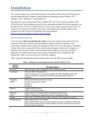
Chapter 1Introduction1.1 Background<strong>Rapid</strong> visual screening <strong>of</strong> buildings <strong>for</strong> potentialseismic hazards, as described herein, originated in1988 with the publication <strong>of</strong> the FEMA 154Report, <strong>Rapid</strong> <strong>Visual</strong> <strong>Screening</strong> <strong>of</strong> <strong>Buildings</strong> <strong>for</strong><strong>Potential</strong> <strong>Seismic</strong> <strong>Hazards</strong>: A Handbook. Written<strong>for</strong> a broad audience ranging from engineers andbuilding <strong>of</strong>ficials to appropriately trainednonpr<strong>of</strong>essionals, the Handbook provided a“sidewalk survey” approach that enabled users toclassify surveyed buildings into two categories:those acceptable as to risk to life safety or thosethat may be seismically hazardous and should beevaluated in more detail by a design pr<strong>of</strong>essionalexperienced in seismic design.During the decade following publication <strong>of</strong> thefirst edition <strong>of</strong> the FEMA 154 Handbook, the rapidvisual screening (RVS) procedure was used byprivate-sector organizations and governmentagencies to evaluate more than 70,000 buildingsnationwide (ATC, 2002). This widespreadapplication provided important in<strong>for</strong>mation aboutthe purposes <strong>for</strong> which the documentwas used, the ease-<strong>of</strong>-use <strong>of</strong> thedocument, and perspectives on theaccuracy <strong>of</strong> the scoring system uponwhich the procedure was based.Concurrent with the widespreaduse <strong>of</strong> the document, damagingearthquakes occurred in Cali<strong>for</strong>niaand elsewhere, and extensiveresearch and development ef<strong>for</strong>tswere carried out under the NationalEarthquake <strong>Hazards</strong> ReductionProgram (NEHRP). These ef<strong>for</strong>tsyielded important new data on theper<strong>for</strong>mance <strong>of</strong> buildings inearthquakes, and on the expecteddistribution, severity, and occurrence<strong>of</strong> earthquake-induced groundshaking.The data and in<strong>for</strong>mationgathered during the first decade afterpublication (experience in applyingthe original Handbook, new buildingearthquake per<strong>for</strong>mance data, andnew ground shaking in<strong>for</strong>mation)Figure 1-1have been used to update and improve the rapidvisual screening procedure provided in this secondedition <strong>of</strong> the FEMA 154 Report, <strong>Rapid</strong> <strong>Visual</strong><strong>Screening</strong> <strong>of</strong> <strong>Buildings</strong> <strong>for</strong> <strong>Potential</strong> <strong>Seismic</strong><strong>Hazards</strong>: A Handbook. The revised RVSprocedure retains the same framework andapproach <strong>of</strong> the original procedure, butincorporates a revised scoring system compatiblewith the ground motion criteria in the FEMA 310Report, Handbook <strong>for</strong> <strong>Seismic</strong> Evaluation <strong>of</strong><strong>Buildings</strong>—A Prestandard (ASCE, 1998), and thedamage estimation data provided in the recentlydeveloped FEMA-funded HAZUS damage andloss estimation methodology (NIBS, 1999). As inthe original Handbook, a Data Collection Form isprovided <strong>for</strong> each <strong>of</strong> three seismicity regions: low,moderate, and high. However, the boundaries <strong>of</strong>the low, moderate, and high seismicity regions inthe original Handbook have been modified (Figure1-1), reflecting new knowledge on the expecteddistribution, severity, and occurrence <strong>of</strong>earthquake ground shaking, and a change in theNote: <strong>Seismic</strong>ity regions are based on ground motions havinga 2% probability <strong>of</strong> exceedance in 50 years.High, moderate, and low seismicity regions <strong>of</strong> the conterminousUnited States. A different RVS Data Collection Form has beendeveloped <strong>for</strong> each <strong>of</strong> these regions. Enlarged maps are availablein Appendix A.FEMA-154 1: Introduction 1
ecurrence interval considered, from a 475-yearaverage return period (corresponding to groundmotions having a 10% probability <strong>of</strong> exceedancein 50 years) to a 2475-year average return period(corresponding to ground motions having a 2%probability <strong>of</strong> excedance in 50 years).This second edition <strong>of</strong> the FEMA 154Handbook has been shortened and focused t<strong>of</strong>acilitate implementation. Other improvementsinclude:• guidance on planning and managing an RVSsurvey, including the training <strong>of</strong> screeners andthe acquisition <strong>of</strong> data from assessor files andother sources to obtain more reliablein<strong>for</strong>mation on age, structural system, andoccupancy;• more guidance <strong>for</strong> identifying the structural(lateral-load-resisting) system in the field;• the use <strong>of</strong> interior inspection or pre-surveyreviews <strong>of</strong> building plans to identify (orverify) a building’s lateral-load-resistingsystem;• updated Basic Structural Hazard Scores andScore Modifiers that are derived fromanalytical calculations and recently developedHAZUS fragility curves <strong>for</strong> the modelbuilding types considered by the RVSmethodology;• the use <strong>of</strong> new seismic hazard in<strong>for</strong>mation thatis compatible with seismic hazard criteriaspecified in other related FEMA documents(see Section 1.4 below); and• a revised Data Collection Form that providesspace <strong>for</strong> documenting soil type, additionaloptions <strong>for</strong> documenting falling hazards, andan expanded list <strong>of</strong> occupancy types.1.2 <strong>Screening</strong> Procedure Purpose,Overview, and ScopeThe RVS procedure presented in this Handbookhas been <strong>for</strong>mulated to identify, inventory, andrank buildings that are potentially seismicallyhazardous. Developed <strong>for</strong> a broad audience thatincludes building <strong>of</strong>ficials and inspectors,government agencies, design pr<strong>of</strong>essionals,private-sector building owners (particularly thosethat own or operate clusters or groups <strong>of</strong>buildings), faculty members who use the RVSprocedure as a training tool, and in<strong>for</strong>medappropriately trained, members <strong>of</strong> the public, theRVS procedure can be implemented relativelyquickly and inexpensively to develop a list <strong>of</strong>potentially hazardous buildings without the highcost <strong>of</strong> a detailed seismic analysis <strong>of</strong> individualbuildings. If a building receives a high score (i.e.,above a specified cut-<strong>of</strong>f score, as discussed laterin this Handbook), the building is considered tohave adequate seismic resistance. If a buildingreceives a low score on the basis <strong>of</strong> this RVSprocedure, it should be evaluated by a pr<strong>of</strong>essionalengineer having experience or training in seismicdesign. On the basis <strong>of</strong> this detailed inspection,engineering analyses, and other detailedprocedures, a final determination <strong>of</strong> the seismicadequacy and need <strong>for</strong> rehabilitation can be made.During the planning stage, which is discussedin Chapter 2, the organization that is conductingthe RVS procedure (hereinafter, the “RVSauthority”) will need to specify how the resultsfrom the survey will be used. If the RVS authoritydetermines that a low score automatically requiresthat further study be per<strong>for</strong>med by a pr<strong>of</strong>essionalengineer, then some acceptable level <strong>of</strong>qualification held by the inspectors per<strong>for</strong>ming thescreening will be necessary. RVS projects have awide range <strong>of</strong> goals and they have constraints onbudget, completion date and accuracy, which mustbe considered by the RVS authority as it selectsqualification requirements <strong>of</strong> the screeningpersonnel. Under most circumstances, a wellplannedand thorough RVS project will requireengineers to per<strong>for</strong>m the inspections. In any case,the program should be overseen by a designpr<strong>of</strong>essional knowledgeable in seismic design <strong>for</strong>quality assurance purposes.The RVS procedure in this Handbook isdesigned to be implemented without per<strong>for</strong>mingstructural analysis calculations. The RVSprocedure utilizes a scoring system that requiresthe user to (1) identify the primary structurallateral-load-resisting system; and (2) identifybuilding attributes that modify the seismicper<strong>for</strong>mance expected <strong>of</strong> this lateral-load-resistingsystem. The inspection, data collection, anddecision-making process typically will occur at thebuilding site, taking an average <strong>of</strong> 15 to 30minutes per building (30 minutes to one hour ifaccess to the interior is available). Results arerecorded on one <strong>of</strong> three Data Collection Forms(Figure 1-2), depending on the seismicity <strong>of</strong> theregion being surveyed. The Data Collection Form,described in greater detail in Chapter 3, includesspace <strong>for</strong> documenting building identificationin<strong>for</strong>mation, including its use and size, aphotograph <strong>of</strong> the building, sketches, anddocumentation <strong>of</strong> pertinent data related to seismicper<strong>for</strong>mance, including the development <strong>of</strong> a2 1: Introduction FEMA 154
numeric seismic hazard score.The scores are based on averageexpected ground shaking levels <strong>for</strong>the seismicity region as well as theseismic design and constructionpractices <strong>for</strong> that region 1 .<strong>Buildings</strong> may be reviewed fromthe sidewalk without the benefit <strong>of</strong>building entry, structuraldrawings, or structuralcalculations. Reliability andconfidence in building attributedetermination are increased,however, if the structural framingsystem can be verified duringinterior inspection, or on the basis<strong>of</strong> a review <strong>of</strong> constructiondocuments.The RVS procedure isintended to be applicablenationwide, <strong>for</strong> all conventionalbuilding types. Bridges, largetowers, and other non-buildingstructure types, however, are notcovered by the procedure. Due tobudget or other constraints, someRVS authorities may wish torestrict their RVS to identifyingbuilding types that they considerthe most hazardous, such asunrein<strong>for</strong>ced masonry ornonductile concrete buildings.However, it is recommended, atleast initially, that all conventionalbuilding types be considered, andthat elimination <strong>of</strong> certain buildingtypes from the screening be welldocumented and supported with Figure 1-2<strong>of</strong>fice calculations and fieldsurvey data that justify theirelimination. It is possible that, in some cases,even buildings designed to modern codes, such asthose with configurations that induce extremetorsional response and those with abrupt changesin stiffness, may be potentially hazardous.1 <strong>Seismic</strong> design and construction practices vary byseismicity region, with little or no seismic designrequirements in low seismicity regions, moderateseismic design requirements in moderate seismicityregions, and extensive seismic design requirements inhigh seismicity regions. The requirements also varywith time, and are routinely updated to reflect newknowledge about building seismic per<strong>for</strong>mance.Data Collection Forms <strong>for</strong> the three designatedseismicity regions (low, moderate, and high).1.3 Companion FEMA 155 ReportA companion volume to this report, <strong>Rapid</strong> <strong>Visual</strong><strong>Screening</strong> <strong>of</strong> <strong>Buildings</strong> <strong>for</strong> <strong>Potential</strong> <strong>Seismic</strong><strong>Hazards</strong>: Supporting Documentation (secondedition) (FEMA 155) documents the technicalbasis <strong>for</strong> the RVS procedure described in thisHandbook, including the method <strong>for</strong> calculatingthe Basic Structural Scores and Score Modifiers.The FEMA 155 report (ATC, 2002) alsosummarizes other in<strong>for</strong>mation considered duringdevelopment <strong>of</strong> this Handbook, including theef<strong>for</strong>ts to solicit user feedback and a FEMA 154Users Workshop held in September 2000. TheFEMA 155 document is available from FEMA byFEMA 154 1: Introduction 3
dialing 1-800-480-2520 and should be consulted<strong>for</strong> any needed or desired supportingdocumentation.1.4 Relationship <strong>of</strong> FEMA 154 toOther Documents in the FEMAExisting Building SeriesThe FEMA 154 Handbook has been developed asan integral and fundamental part <strong>of</strong> the FEMAreport series on seismic safety <strong>of</strong> existingbuildings. It is intended <strong>for</strong> use by designpr<strong>of</strong>essionals and others to mitigate the damagingeffects <strong>of</strong> earthquakes on existing buildings. Theseries includes:• FEMA 154 (this handbook), which provides aprocedure that can be rapidly implemented toidentify buildings that are potentiallyseismically hazardous.• FEMA 310, Handbook <strong>for</strong> <strong>Seismic</strong> Evaluation<strong>of</strong> <strong>Buildings</strong>—A Prestandard (ASCE, 1998),which provides a procedure to inspect in detaila given building to evaluate its seismicresisting capacity (an updated version <strong>of</strong> theFEMA 178 NEHRP Handbook <strong>for</strong> the <strong>Seismic</strong>Evaluation <strong>of</strong> Existing <strong>Buildings</strong> [BSSC,1992]). The FEMA 310 Handbook is ideallysuited <strong>for</strong> use on those buildings identified bythe FEMA 154 RVS procedure as potentiallyhazardous.FEMA 310 is expected to be superseded in2002 by ASCE 31, a standard <strong>of</strong> the AmericanSociety <strong>of</strong> Civil Engineers approved by theAmerican National Standards Institute(ANSI). References in this Handbook toFEMA 310 should then refer to ASCE 31.• FEMA 356, Prestandard and Commentary <strong>for</strong>the <strong>Seismic</strong> Rehabilitation <strong>of</strong> <strong>Buildings</strong>(ASCE, 2000), which provides recommendedprocedures <strong>for</strong> the seismic rehabilitation <strong>of</strong>buildings with inadequate seismic capacity, asdetermined, <strong>for</strong> example, by a FEMA 310 (orFEMA 178) evaluation. The FEMA 356Prestandard is based on the guidance providedin the FEMA 273 NEHRP Guidelines <strong>for</strong> the<strong>Seismic</strong> Rehabilitation <strong>of</strong> <strong>Buildings</strong> (ATC,1997a), and companion FEMA 274Commentary on the NEHRP Guidelines <strong>for</strong>the <strong>Seismic</strong> Rehabilitation <strong>of</strong> <strong>Buildings</strong> (ATC,1997b).1.5 Uses <strong>of</strong> RVS Survey ResultsWhile the principal purpose <strong>of</strong> the RVS procedureis to identify potentially seismically hazardousbuildings needing further evaluation, results fromRVS surveys can also be used <strong>for</strong> other purposes.These include: (1) ranking a community’s (oragency’s) seismic rehabilitation needs; (2)designing seismic hazard mitigation programs <strong>for</strong>a community (or agency); (3) developinginventories <strong>of</strong> buildings <strong>for</strong> use in regionalearthquake damage and loss impact assessments;(4) planning postearthquake building safetyevaluation ef<strong>for</strong>ts; and (5) developing buildingspecificseismic vulnerability in<strong>for</strong>mation <strong>for</strong>purposes such as insurance rating, decisionmaking during building ownership transfers, andpossible triggering <strong>of</strong> remodeling requirementsduring the permitting process. Additionaldiscussion on the use <strong>of</strong> RVS survey results isprovided in Chapter 4.1.6 How to Use this HandbookThe Handbook has been designed to facilitate theplanning and execution <strong>of</strong> rapid visual screening.It is assumed that the RVS authority has alreadydecided to conduct the survey, and that detailedguidance is needed <strong>for</strong> all aspects <strong>of</strong> the surveyingprocess. There<strong>for</strong>e, the main body <strong>of</strong> theHandbook focuses on the three principal activitiesin the RVS: planning, execution, and datainterpretation. Chapter 2 contains detailedin<strong>for</strong>mation on planning and managing an RVS.Chapter 3 describes in detail how the DataCollection Form should be completed, andChapter 4 provides guidance on interpreting andusing the results from the RVS. Finally, Chapter 5provides several example applications <strong>of</strong> the RVSprocedure on real buildings.Relevant seismic hazard maps, full-sized DataCollection Forms, including a Quick ReferenceGuide <strong>for</strong> RVS implementation, guidance <strong>for</strong>reviewing design and construction drawings, andadditional guidance <strong>for</strong> identifying a building’sseismic lateral-load-resisting system from thestreet are provided in Appendices A, B, C, and D,respectively. Appendix E provides additionalin<strong>for</strong>mation on the building types considered inthe RVS procedure, and Appendix F provides anoverview <strong>of</strong> earthquake fundamentals, theseismicity <strong>of</strong> the United States, and earthquakeeffects.4 1: Introduction FEMA 154
Chapter 2Planning and Managing<strong>Rapid</strong> <strong>Visual</strong> <strong>Screening</strong>Once the decision to conduct rapid visualscreening (RVS) <strong>for</strong> a community or group <strong>of</strong>buildings has been made by the RVS authority, thescreening ef<strong>for</strong>t can be expedited by pre-planningand careful overall management <strong>of</strong> theprocess. This chapter describes the overallscreening implementation sequence andprovides detailed in<strong>for</strong>mation on importantpre-planning and management aspects.Instructions on how to complete the DataCollection Form are provided in Chapter 3.screened, selection and development <strong>of</strong> arecord-keeping system, and compilation anddevelopment <strong>of</strong> maps that document localseismic hazard in<strong>for</strong>mation;Develop budgetand cost estimatePre-plan field survey andidentify the area to bescreened2.1 <strong>Screening</strong> ImplementationSequenceThere are several steps involved inplanning and per<strong>for</strong>ming an RVS <strong>of</strong>potentially seismically hazardous buildings.As a first step, if it is to be a public orcommunity project, the local governingbody and local building <strong>of</strong>ficials should<strong>for</strong>mally approve <strong>of</strong> the general procedure.Second, the public or the members <strong>of</strong> thecommunity should be in<strong>for</strong>med about thepurpose <strong>of</strong> the screening process and how itwill be carried out. There are also otherdecisions to be made, such as use <strong>of</strong> thescreening results, responsibilities <strong>of</strong> thebuilding owners and the community, andactions to be taken. Some <strong>of</strong> thesedecisions are specific to each communityand there<strong>for</strong>e are not discussed in thisHandbook.The general sequence <strong>of</strong> implementingthe RVS procedure is depicted in Figure2-1. The implementation sequenceincludes:• Budget development and costestimation, recognizing the expectedextent <strong>of</strong> the screening and further use<strong>of</strong> the gathered data;• Pre-field planning, including selection<strong>of</strong> the area to be surveyed,identification <strong>of</strong> building types to beChoose your screeners, trainthem and make assignmentsAcquire and reviewpre-field data,including existingbuilding files,databases, and soiltypes <strong>for</strong> thesurveyed areaIf you have accessto the interior, verifyconstruction typeand planirregularitiesPhotograph the building withinstant or digital cameraReview existingconstructiondrawings, ifavailable to verifyage, size,construction type,and irregularitiesCheck <strong>for</strong>quality andfile the fielddata in therecord keepingsystemSelect and reviewData CollectionFormScreen the buildingfrom the exterior onall available sides;sketch the plan andelevationFigure 2-1 <strong>Rapid</strong> visual screening implementation sequence.FEMA 154 2: Planning and Managing <strong>Rapid</strong> <strong>Visual</strong> <strong>Screening</strong> 5
• Selection and review <strong>of</strong> the Data CollectionForm;• Selection and training <strong>of</strong> screening personnel;• Acquisition and review <strong>of</strong> pre-field data;including review <strong>of</strong> existing building files anddatabases to document in<strong>for</strong>mation identifyingbuildings to be screened (e.g., address, lotnumber, number <strong>of</strong> stories, design date) andidentifying soil types <strong>for</strong> the survey area;• Review <strong>of</strong> existing building plans, if available;• Field screening <strong>of</strong> individual buildings (seeChapter 3 <strong>for</strong> details), which consists <strong>of</strong>:1. Verifying and updating buildingidentification in<strong>for</strong>mation,2. Walking around the building andsketching a plan and elevation view on theData Collection Form,3. Determining occupancy (that is, thebuilding use and number <strong>of</strong> occupants),4. Determining soil type, if not identifiedduring the pre-planning process,5. Identifying potential nonstructural fallinghazards,6. Identifying the seismic-lateral-loadresistingsystem (entering the building, ifpossible, to facilitate this process) andcircling the Basic Structural Hazard Scoreon the Data Collection Form,7. Identifying and circling the appropriateseismic per<strong>for</strong>mance attribute ScoreModifiers (e.g., number <strong>of</strong> stories, designdate, and soil type) on the Data CollectionForm,8. Determining the Final Score, S (byadjusting the Basic Structural HazardScore with the Score Modifiers identifiedin Step 7), and deciding if a detailedevaluation is required, and9. Photographing the building; and• Checking the quality and filing the screeningdata in the record-keeping system, or database.2.2 Budget Development and CostEstimationMany <strong>of</strong> the decisions that are made about thelevel <strong>of</strong> detail documented during the rapid visualscreening procedure will depend upon budgetconstraints. Although the RVS procedure isdesigned so field screening <strong>of</strong> each buildingshould take no more than 15 to 30 minutes (30minutes to one hour if access to the interior isobtained), time and funds should also be allocated<strong>for</strong> pre-field data collection. Pre-field datacollection can be time consuming (10 to 30minutes per building depending on the type <strong>of</strong>supplemental data available). However, it can beextremely useful in reducing the total field timeand can increase the reliability <strong>of</strong> data collected inthe field. A good example <strong>of</strong> this is the age, ordesign date, <strong>of</strong> a building. This might be readilyavailable from building department files but ismuch more difficult to estimate from the street.Another issue to consider is travel time, if thedistance between buildings to be screened is large.Because pre-field data collection and travel timecould be a significant factor in budget allocations,it should be considered in the planning phase.Other factors that should be considered in costestimation are training <strong>of</strong> personnel and thedevelopment and administration <strong>of</strong> a recordkeepingsystem <strong>for</strong> the screening process. Thetype <strong>of</strong> record keeping system selected will be afunction <strong>of</strong> existing procedures and availablefunds as well as the ultimate goal <strong>of</strong> the screening.For example, if the screening is to be used solely<strong>for</strong> potential seismic damage estimation purposes,administrative costs will be different from those <strong>of</strong>a screening in which owners <strong>of</strong> low-scoringbuildings must subsequently be notified, andcompliance with ordinances is required.2.3 Pre-Field PlanningThe RVS authority may decide due to budget, timeor other types <strong>of</strong> constraints, that priorities shouldbe set and certain areas within the region shouldbe surveyed immediately, whereas other areas canbe surveyed at a later time because they areassumed to be less hazardous. An area may beselected because it is older and may have a higherdensity <strong>of</strong> potentially seismically hazardousbuildings relative to other areas. For example anolder part <strong>of</strong> the RVS authority region that consistsmainly <strong>of</strong> commercial unrein<strong>for</strong>ced masonrybuildings may be <strong>of</strong> higher priority than a newerarea with mostly warehouse facilities, or aresidential section <strong>of</strong> a city consisting <strong>of</strong> woodframesingle-family dwellings.Compiling and developing maps <strong>for</strong> thesurveyed region is important in the initial planningphase as well as in scheduling <strong>of</strong> screeners. Maps<strong>of</strong> soil pr<strong>of</strong>iles, although limited, will be directlyuseful in the screening, and maps <strong>of</strong> landslidepotential, liquefaction potential, and active faults6 2: Planning and Managing <strong>Rapid</strong> <strong>Visual</strong> <strong>Screening</strong> FEMA 154
provide useful background in<strong>for</strong>mation about therelative hazard in different areas. Maps <strong>of</strong> lotswill be useful in scheduling screeners and, as dataare collected, in identifying areas with largenumbers <strong>of</strong> potentially hazardous buildings.Another important phase <strong>of</strong> pre-field planningis interaction with the local design pr<strong>of</strong>ession andbuilding <strong>of</strong>ficials. Discussions should includeverification <strong>of</strong> when certain aspects <strong>of</strong> seismicdesign and detailing were adopted and en<strong>for</strong>ced.This will be used in adjusting the scoring system<strong>for</strong> local practices and specifying benchmarkyears.The record-keeping system will vary amongRVS authorities, depending on needs, goals,budgets and other constraints, and may in factconsist <strong>of</strong> several systems. Part <strong>of</strong> this planningphase may include deciding how buildings are tobe identified. Some suggestions are street address,assessor’s parcel number, census tract, and lotnumber or owner. Consideration should be givento developing a computerized database containinglocation and other building in<strong>for</strong>mation, whichcould easily be used to generate peel-<strong>of</strong>f labels<strong>for</strong> the Data Collection Form, or to generate<strong>for</strong>ms that incorporate unique in<strong>for</strong>mation <strong>for</strong>each building.The advantage <strong>of</strong> using a computerizedrecord generation and collection system is thatgraphical data, such as sketches andphotographs, are increasingly more easilyconverted to digital <strong>for</strong>m and stored on thecomputer, especially if they are collected indigital <strong>for</strong>mat in the field. This can befacilitated through the use <strong>of</strong> personal digitalassistants (PDAs), which would require thedevelopment <strong>of</strong> a FEMA 154 application, andthe use <strong>of</strong> digital cameras.If a computerized database is not used,micr<strong>of</strong>ilm is a good storage medium <strong>for</strong>original hard copy, because photographs,building plans, screening <strong>for</strong>ms and subsequentfollow-up documentation can be kept togetherand easily copied. Another method that hasbeen used is to generate a separate hard-copyfile <strong>for</strong> each building as it is screened. In fact,the screening <strong>for</strong>m can be reproduced on alarge envelope and all supporting material andphotographs stored inside. This solves anyproblems associated with attaching multiplesketches and photographs, but the files growrapidly and may become unmanageable.2.4 Selection and Review <strong>of</strong> theData Collection FormThere are three Data Collection Forms, one <strong>for</strong>each <strong>of</strong> the following three regions <strong>of</strong> seismicity:low (L), moderate (M), and high (H). Full-sizedversions <strong>of</strong> each <strong>for</strong>m are provided in Appendix B,along with a Quick Reference Guide that containsdefinitions and explanations <strong>for</strong> terms used on theData Collection Form. Each Data Collection Form(see example, Figure 2-2) provides space torecord the building identification in<strong>for</strong>mation,draw a sketch <strong>of</strong> the building (plan andelevation views), attach a photograph <strong>of</strong> thebuilding, indicate the occupancy, indicate the soiltype, document the existence <strong>of</strong> falling hazards,develop a Final Structural Score, S, <strong>for</strong> thebuilding, indicate if a detailed evaluation isrequired, and provide additional comments. Thestructural scoring system consists <strong>of</strong> a matrix <strong>of</strong>Basic Structural Hazard Scores (one <strong>for</strong> eachbuilding type and its associated seismic lateral<strong>for</strong>ce-resistingsystem) and Score Modifiers toFigure 2-2Example RVS Data Collection Form (highseismicity).FEMA 154 2: Planning and Managing <strong>Rapid</strong> <strong>Visual</strong> <strong>Screening</strong> 7
account <strong>for</strong> observed attributes that modifyseismic per<strong>for</strong>mance. The Basic Structural HazardScores and Score Modifiers are based on (1)design and construction practices in the region, (2)attributes known to decrease or increase seismicresistance capacity, and (3) maximum consideredground motions <strong>for</strong> the seismicity region underconsideration. The Basic Structural Hazard Score,Score Modifiers, and Final Structural Score, S, allrelate to the probability <strong>of</strong> building collapse,should the maximum ground motions consideredby the RVS procedure occur at the site. Final Sscores typically range from 0 to 7, with higher Sscores corresponding to better seismicper<strong>for</strong>mance.The maximum ground motions considered inthe scoring system <strong>of</strong> the RVS procedure areconsistent with those specified <strong>for</strong> detailedbuilding seismic evaluation in the FEMA 310Report, Handbook <strong>for</strong> the <strong>Seismic</strong> Evaluation <strong>of</strong><strong>Buildings</strong>—A Prestandard. Such ground motionsgenerally have a 2% chance <strong>of</strong> being exceeded in50 years, and are multiplied by a 2/3 factor in theFEMA 310 evaluation procedures and in thedesign requirements <strong>for</strong> new buildings in FEMA302, Recommended Provisions <strong>for</strong> <strong>Seismic</strong>Regulations <strong>for</strong> New <strong>Buildings</strong> and OtherStructures (BSSC, 1997). (Ground motions havinga 2% probability <strong>of</strong> being exceeded in 50 years arecommonly referred to as the maximum consideredearthquake (MCE) ground motions.)2.4.1 Determination <strong>of</strong> <strong>Seismic</strong>ity RegionTo select the appropriate Data Collection Form,it is first necessary to determine the seismicityregion in which the area to be screened is located.The seismicity region (H, M, or L) <strong>for</strong> the screeningarea can be determined by one <strong>of</strong> two methods:1. Find the location <strong>of</strong> the surveyed region on theseismicity map <strong>of</strong> Figure 1-1, or one <strong>of</strong> theenlarged seismicity maps provided in AppendixA, and identify the corresponding seismicityregion, or;2. Access the U.S. Geological Survey web page(http://geohazards.cr.usgs.gov/eq/), select“Hazard by Zip Code” or “Hazard by Lat/Long”under the “<strong>Seismic</strong> Hazard” heading, enter theappropriate values <strong>of</strong> zip code or latitude andlongitude, select the spectral acceleration value(SA) <strong>for</strong> a period <strong>of</strong> 0.2 seconds and the SAvalue <strong>for</strong> a period <strong>of</strong> 1.0 second, multiply the SAvalues by 2/3, and use the criteria <strong>of</strong> Table 2-1 toselect the appropriate seismicity region,assuming that the highest seismicity leveldefined by the parameters in Table 2-1 shallgovern.Use more recent additions <strong>of</strong> these maps whenthey become available.The web site approach <strong>of</strong> Method 2, which usesseismicity region definitions used in other recentlydeveloped FEMA documents, is preferred as itenables the user to determine seismicity based on amore precisely specified location. In contrast, eachcounty shown in Figure 1-1 is assigned its seismicityon the basis <strong>of</strong> the highest seismicity in that county,even though it may only apply to a small portion <strong>of</strong>the county.Table 2-1Region <strong>of</strong><strong>Seismic</strong>ityLowModerateRegions <strong>of</strong> <strong>Seismic</strong>ity withCorresponding Spectral AccelerationResponse (from FEMA 310)Spectral AccelerationResponse, SA (shortperiod,or 0.2 sec)less than 0.167 g (inhorizontal direction)greater than or equalto 0.167 g but lessthan 0.500 g (inhorizontal direction)High greater than or equalto 0.500 g (inhorizontal direction)Notes: g = acceleration <strong>of</strong> gravitySpectral AccelerationResponse, SA (longperiodor 1.0 sec)less than 0.067 g (inhorizontal direction)greater than or equalto 0.067 g but lessthan 0.200 g (inhorizontal direction)greater than or equalto 0.200 g (inhorizontal direction)2.4.2 Determination <strong>of</strong> Key <strong>Seismic</strong> CodeAdoption Dates and OtherConsiderationsThe Data Collection Form is meant to be amodel that may be adopted and used as it ispresented in this Handbook. The <strong>for</strong>m may also bemodified according to the needs <strong>of</strong> the RVSauthority. There<strong>for</strong>e, another aspect <strong>of</strong> thescreening planning process is to review the DataCollection Form to determine if all required dataare represented or if modifications should be madeto reflect the needs and special circumstances <strong>of</strong>the authority. For example, an RVS authority maychoose to define additional occupancy classes suchas “parking structure” or “multi-familyresidential.”One <strong>of</strong> the key issues that must be addressedin the planning process is the determination <strong>of</strong> (1)the year in which seismic codes were initially8 2: Planning and Managing <strong>Rapid</strong> <strong>Visual</strong> <strong>Screening</strong> FEMA 154
Table 2-2. Benchmark Years <strong>for</strong> RVS Procedure Building Types (based on FEMA 310)Model Building <strong>Seismic</strong> Design ProvisionsBuilding Type BOCA SBCC UBC NEHRPW1: Light wood-frame residential and commercial buildingssmaller than or equal to 5,000 square feet1992 1993 1976 1985W2: Light wood-frame buildings larger than 5,000 squarefeet1992 1993 1976 1985S1: Steel moment-resisting frame buildings ** ** 1994 **S2: Braced steel frame buildings 1992 1993 1988 1991S3: Light metal buildings * * * *S4: Steel frame buildings with cast-in-place concrete shearwalls1992 1993 1976 1985S5: Steel frame buildings with unrein<strong>for</strong>ced masonry infillwalls* * * *C1: Concrete moment-resisting frame buildings 1992 1993 1976 1985C2: Concrete shear-wall buildings 1992 1993 1976 1985C3: Concrete frame buildings with unrein<strong>for</strong>ced masonryinfill walls* * * *PC1: Tilt-up buildings * * 1997 *PC2: Precast concrete frame buildings * * * *RM1: Rein<strong>for</strong>ced masonry buildings with flexible floor andro<strong>of</strong> diaphragms* * 1997 *RM2: Rein<strong>for</strong>ced masonry buildings with rigid floor and ro<strong>of</strong>diaphragms1992 1993 1976 1985URM: Unrein<strong>for</strong>ced masonry bearing-wall buildings * * 1991 **No benchmark year; **contact local building department <strong>for</strong> benchmark year.BOCA: Building Officials and Code Administrators, National Building CodeSBCC: Southern Building Code Congress, Standard Building Code.UBC: International Conference <strong>of</strong> Building Officials, Uni<strong>for</strong>m Building CodeNEHRP: National Earthquake Hazard Reduction Program, FEMA 302 Recommended Provisions <strong>for</strong> the Development <strong>of</strong> <strong>Seismic</strong>Regulations <strong>for</strong> New <strong>Buildings</strong>adopted and en<strong>for</strong>ced by the local jurisdiction, and(2) the year in which significantly improvedseismic codes were adopted and en<strong>for</strong>ced (thislatter year is known as the benchmark year). Inhigh and moderate seismicity regions, the BasicStructural Hazard Scores <strong>for</strong> the various buildingtypes are calculated <strong>for</strong> buildings built after theinitial adoption <strong>of</strong> seismic codes, but be<strong>for</strong>esubstantially improved codes were adopted. Forthese regions, Score Modifiers designated as “PreCode” and “Post Benchmark” are provided,respectively, <strong>for</strong> buildings built be<strong>for</strong>e theadoption <strong>of</strong> codes and <strong>for</strong> buildings built after theadoption <strong>of</strong> substantially improved codes. In lowseismicity regions, the Basic Structural HazardScores are calculated <strong>for</strong> buildings built be<strong>for</strong>e theinitial adoption <strong>of</strong> seismic codes. For buildings inthese regions, the Score Modifier designated as“Pre Code” is not applicable (N/A), and the ScoreModifier designated as “Post Benchmark” isapplicable <strong>for</strong> buildings built after the adoption <strong>of</strong>seismic codes.There<strong>for</strong>e, as part <strong>of</strong> this review process, theRVS authority should identify (1) the year inwhich seismic codes were first adopted anden<strong>for</strong>ced in the area to be screened, (2) the“benchmark” year in which significantly improvedseismic code requirements were adopted <strong>for</strong> eachbuilding type considered by the RVS procedure(see Table 2-2), and (3) the year in which thecommunity adopted seismic anchoragerequirements <strong>for</strong> heavy cladding. If the RVSauthority in high and moderate seismicity regionsis unsure <strong>of</strong> the year(s) in which codes wereinitially adopted, the default year <strong>for</strong> all but onebuilding type is 1941 (the default year specified inthe HAZUS criteria; NIBS, 1999). The oneexception is PC1 (tilt-up) buildings, <strong>for</strong> which it isassumed that seismic codes were initially adoptedin 1973, the year in which wall-diaphragm (ledger)connection requirements first appeared in theUni<strong>for</strong>m Building Code (ICBO, 1973).During the review <strong>of</strong> the Data CollectionForm, the RVS authority should confer with theFEMA 154 2: Planning and Managing <strong>Rapid</strong> <strong>Visual</strong> <strong>Screening</strong> 9
1. Model Building Types and Critical Code Adoptionand En<strong>for</strong>cement Dates Year <strong>Seismic</strong> Codes BenchmarkInitially Adopted Year WhenStructure Types and En<strong>for</strong>ced* Codes ImprovedW1 Light wood frame, residential or commercial, < 5000 square feet _______ _______W2 Wood frame buildings, > 5000 square feet _______ _______S1 Steel moment-resisting frame _______ _______S2 Steel braced frame _______ _______S3 Light metal frame _______ _______S4 Steel frame with cast-in-place concrete shear walls _______ _______S5 Steel frame with unrein<strong>for</strong>ced masonry infill _______ _______C1 Concrete moment-resisting frame _______ _______C2 Concrete shear wall _______ _______C3 Concrete frame with unrein<strong>for</strong>ced masonry infill _______ _______PC1 Tilt-up construction _______ _______PC2 Precast concrete frame _______ _______RM1 Rein<strong>for</strong>ced masonry with flexible floor and ro<strong>of</strong> diaphragms _______ _______RM2 Rein<strong>for</strong>ced masonry with rigid diaphragms _______ _______URM Unrein<strong>for</strong>ced masonry bearing-wall buildings _______ _______*Not applicable in regions <strong>of</strong> low seismicity2. Anchorage <strong>of</strong> Heavy CladdingYear in which seismic anchorage requirements were adopted:_______Figure 2-3 Sections 1 and 2 <strong>of</strong> Quick Reference Guide (<strong>for</strong> use with Data Collection Form).chief building <strong>of</strong>ficial, plan checkers, and otherdesign pr<strong>of</strong>essionals experienced in seismic designto identify the years in which the affectedjurisdiction initially adopted and en<strong>for</strong>ced seismiccodes (if ever) <strong>for</strong> the building lateral-<strong>for</strong>ceresistingstructural systems considered by the RVSprocedure. Since municipal codes are generallyadopted by the city council, another source <strong>for</strong> thisin<strong>for</strong>mation, in many municipalities, is the cityclerk’s <strong>of</strong>fice. In addition to determining the yearin which seismic codes were initially adopted anden<strong>for</strong>ced, the RVS authority should also determine(1) the benchmark years in which substantiallyimproved seismic codes were adopted anden<strong>for</strong>ced <strong>for</strong> the various lateral-load-resistingsystems and (2) the year in which anchoragerequirements <strong>for</strong> cladding were adopted anden<strong>for</strong>ced. These dates should be inserted on theQuick Reference Guide (Appendix B) that hasbeen created to facilitate the use <strong>of</strong> the DataCollection Form (see Figure 2-3).During the Data Collection Form reviewprocess, it is critically important that the BasicStructural Hazard Scores and Score Modifiers,which are described in detail in Chapter 3, not bechanged without input from pr<strong>of</strong>essional engineersfamiliar with earthquake-resistant design andconstruction practices <strong>of</strong> the local community. Achecklist <strong>of</strong> issues to be considered whenreviewing the Data Collection Form is provided inTable 2-3.Table 2-3 Checklist <strong>of</strong> Issues to be ConsideredDuring Pre-Field Work Review <strong>of</strong> theData Collection FormEvaluate completeness <strong>of</strong> occupancy categoriesand appropriateness <strong>of</strong> occupancy loadsDetermine year in which seismic codes wereinitially adopted in the jurisdictionDetermine “benchmark” years in which thejurisdiction adopted and en<strong>for</strong>ced significantlyimproved seismic codes <strong>for</strong> the various buildingtypes considered by the RVS procedureDetermine year in which the jurisdictionadopted and en<strong>for</strong>ced anchorage requirements<strong>for</strong> heavy cladding2.4.3 Determination <strong>of</strong> Cut-Off ScoreUse <strong>of</strong> the RVS on a community-wide basisenables the RVS authority to divide screenedbuildings into two categories: those that areexpected to have acceptable seismic per<strong>for</strong>mance,and those that may be seismically hazardous and10 2: Planning and Managing <strong>Rapid</strong> <strong>Visual</strong> <strong>Screening</strong> FEMA 154
should be studied further. This requires that theRVS authority determine, preferably as part <strong>of</strong> thepre-planning process, an appropriate “cut-<strong>of</strong>f”score.An S score <strong>of</strong> 2 is suggested as a “cut-<strong>of</strong>f”,based on present seismic design criteria. Usingthis cut-<strong>of</strong>f level, buildings having an S score <strong>of</strong> 2or less should be investigated by a designpr<strong>of</strong>essional experienced in seismic design (seeSection 3.9, 4.1 and 4.2 <strong>for</strong> additional in<strong>for</strong>mationon this issue).2.5 Qualifications and Training <strong>for</strong>ScreenersIt is anticipated that a training program will berequired to ensure a consistent, high quality <strong>of</strong> thedata and uni<strong>for</strong>mity <strong>of</strong> decisions among screeners.Training should include discussions <strong>of</strong> lateral<strong>for</strong>ce-resistingsystems and how they behave whensubjected to seismic loads, hw to use the DataCollection Form, what to look <strong>for</strong> in the field, andhow to account <strong>for</strong> uncertainty. In conjunctionwith a pr<strong>of</strong>essional engineer experienced inseismic design, screeners should simultaneouslyconsider and score buildings <strong>of</strong> several differenttypes and compare results. This will serve as a“calibration” <strong>for</strong> the screeners.This process can easily be accomplished in aclassroom setting with photographs <strong>of</strong> actualbuildings to use as examples. Prospectivescreeners review the photographs and per<strong>for</strong>m theRVS procedure as though they were on thesidewalk. Upon completion, the class discussesthe results and students can compare how they didin relation to the rest <strong>of</strong> the class.2.6 Acquisition and Review <strong>of</strong> Pre-Field DataIn<strong>for</strong>mation on the structural system, age oroccupancy (that is, use) may be available fromsupplemental sources. These data, from assessorand building department files, insurance (Sanborn)maps, and previous studies, should be reviewedand collated <strong>for</strong> a given area be<strong>for</strong>e commencingthe field survey <strong>for</strong> that area. It is recommendedthat this supplemental in<strong>for</strong>mation either bewritten directly on the Data Collection Forms as itis retrieved or be entered into a computerizeddatabase. The advantage <strong>of</strong> a database is thatselected in<strong>for</strong>mation can be printed in a report<strong>for</strong>mat that can be taken into the field, or printedonto peel-<strong>of</strong>f labels that can be affixed to the DataCollection Form (see Figure 2-4). In addition,screening data can be added to the databases andFigure 2-4 Building identification portion <strong>of</strong> RVSData Collection Form.used to generate maps and reports. Some sources<strong>of</strong> supplemental in<strong>for</strong>mation are described inSections 2.6.1 through 2.6.5.2.6.1 Assessor’s FilesAlthough assessor’s files may contain in<strong>for</strong>mationabout the age <strong>of</strong> the building, the floor area andthe number <strong>of</strong> stories, most in<strong>for</strong>mation relates toownership and assessed value <strong>of</strong> the land andimprovements, and thus is <strong>of</strong> relatively little value<strong>for</strong> RVS purposes. The construction typeindicated is <strong>of</strong>ten incorrect and in most casesshould not be used. In addition, the age <strong>of</strong> abuilding retrieved from assessor’s files may not,and most likely is not, the year that the structurewas built. Usually assessor’s files contain the yearthat the building was first eligible <strong>for</strong> taxation.Because the criteria <strong>for</strong> this may vary, the datemay be several years after the building wasdesigned or constructed. If no other source <strong>of</strong>in<strong>for</strong>mation is available this will give a goodestimate <strong>of</strong> the period during which the buildingFEMA 154 2: Planning and Managing <strong>Rapid</strong> <strong>Visual</strong> <strong>Screening</strong> 11
was constructed. However, this date should not beused to establish conclusively the code underwhich the a building was designed. Assessor’s<strong>of</strong>fices may have parcel or lot maps, which may beuseful <strong>for</strong> locating sites or may be used as atemplate <strong>for</strong> sketching building adjacencies on aparticular city block.2.6.2 Building Department FilesThe extent and completeness <strong>of</strong> in<strong>for</strong>mation inbuilding department files will vary fromjurisdiction to jurisdiction. For example, in somelocations all old files have been removed ordestroyed, so there is no in<strong>for</strong>mation on olderbuildings. In general, files (or micr<strong>of</strong>ilm) maycontain permits, plans and structural calculationsrequired by the city.Sometimes there isoccupancy and usein<strong>for</strong>mation, but littlein<strong>for</strong>mation aboutstructural type will befound except from thereview <strong>of</strong> plans orcalculations.In<strong>for</strong>mation found on a Sanborn map includes:• height <strong>of</strong> building,• number <strong>of</strong> stories,• year built,• thickness <strong>of</strong> walls,• building size (square feet),• type <strong>of</strong> ro<strong>of</strong> (tile, shingle, composite),• building use (dwelling, store, apartment),• presence <strong>of</strong> garage under structure, and• structural type (wood frame, firepro<strong>of</strong>construction, adobe, stone, concrete).2.6.3 Sanborn MapsThese maps, publishedprimarily <strong>for</strong> theinsurance industry sincethe late 1800s, exist <strong>for</strong>about 22,000communities in theUnited States. TheSanborn Map Companystopped routinelyupdating these maps inthe early 1960s, and manycommunities have notkept these maps up-todate.Thus they may notbe useful <strong>for</strong> newerconstruction. However,the maps may containuseful data <strong>for</strong> olderconstruction. They can befound at the library or insome cases in buildingdepartment <strong>of</strong>fices. Figure2-5 provides an example<strong>of</strong> an up-to-date Sanbornmap Figure 2-6 shows akey to identifiers onSanborn maps.Figure 2-5Example Sanborn map showing building in<strong>for</strong>mation <strong>for</strong> a city block.12 2: Planning and Managing <strong>Rapid</strong> <strong>Visual</strong> <strong>Screening</strong> FEMA 154
Figure 2-6Key to Sanborn map symbols. Also, see the Internet, www.sanbornmap.com.Parcel maps are also available and contain lotdimensions. If building size in<strong>for</strong>mation cannot beobtained from another source such as theassessor’s file, the parcel maps are particularlyhelpful <strong>for</strong> determining building dimensions inurban areas where buildings cover the entire lot.However, even if the building does not cover theentire lot, it will be easier to estimate buildingdimensions if the lot dimensions are known.Figures 2-7 and 2-8 show a Sanborn map andphotographs <strong>of</strong> a city block. Building descriptionsobtained from the Sanborn maps are also included.FEMA 154 2: Planning and Managing <strong>Rapid</strong> <strong>Visual</strong> <strong>Screening</strong> 13
1. 10 story commercial <strong>of</strong>fice2. 3 story commercial, built 19133. 2 story commercial4. 3 story commercial, rein<strong>for</strong>ced concrete frame, built 19065. 7 story commercial <strong>of</strong>fice, rein<strong>for</strong>ced concrete frame, built 19236. 2 story commercial, rein<strong>for</strong>ced concrete7. 5 story commercial <strong>of</strong>fice, rein<strong>for</strong>ced concrete8. 20 story commercial <strong>of</strong>fice, steel frame with rein<strong>for</strong>ced concrete, built 19149. 4 story commercial, built 196610. 40 story commercial <strong>of</strong>fice, built 1965-66, concrete and glass exteriorFigure 2-7Sanborn map and corresponding aerial photograph <strong>of</strong> a city block.14 2: Planning and Managing <strong>Rapid</strong> <strong>Visual</strong> <strong>Screening</strong> FEMA 154
Although the in<strong>for</strong>mation onSanborn maps may be useful,it is the responsibility <strong>of</strong> thescreener to verify it in thefield.2.6.4 MunicipalDatabasesWith the widespread use <strong>of</strong>the internet, manyjurisdictions are creating “online”electronic databases <strong>for</strong>use by the general public.These databases providegeneral in<strong>for</strong>mation on thevarious building sites withinthe jurisdiction. Thesedatabases are not detailedenough at this point in time toprovide specific in<strong>for</strong>mationabout the buildings; they do,however, provide some gooddemographic in<strong>for</strong>mation thatcould be <strong>of</strong> use. As themunicipalities develop morecomprehensive in<strong>for</strong>mation,these databases will becomemore useful to the RVSscreening. Figure 2-9 showsexamples <strong>of</strong> the databasesfrom two municipalities in theUnited States.2.6.5 Previous StudiesIn a few cases, previousbuilding inventories or studies<strong>of</strong> hazardous buildings orhazardous nonstructuralelements (e.g.,parapets) may have beenper<strong>for</strong>med. These studies may be limited to aparticular structural or occupancy class, but theymay contain useful maps or other relevantstructural in<strong>for</strong>mation and should be reviewed.Other important studies might address relatedseismic hazard issues such as liquefaction orlandslide potential. Local historical societies mayhave published books or reports about olderbuildings in the community. Fire departments are<strong>of</strong>ten aware <strong>of</strong> the overall condition andcomposition <strong>of</strong> building interiors.Figure 2-8 Photographs <strong>of</strong> elevation views <strong>of</strong> buildings shown in Figure 2-7.2.6.6 Soils In<strong>for</strong>mationSoil type has a major influence on amplitude andduration <strong>of</strong> shaking, and thus structural damage.Generally speaking, the deeper the soils at a site, themore damaging the earthquake motion will be. Thesix soil types considered in the RVS procedure arethe same as those specified in the FEMA 302 report,NEHRP Recommended Provisions <strong>for</strong> the <strong>Seismic</strong>Design <strong>of</strong> New <strong>Buildings</strong> and Other Structures(BSSC, 1997): hard rock (type A); average rock(type B); dense soil (type C), stiff soil (type D); s<strong>of</strong>tsoil (type E), and poor soil (type F). Additionalin<strong>for</strong>mation on these soil types and how to identifyFEMA 154 2: Planning and Managing <strong>Rapid</strong> <strong>Visual</strong> <strong>Screening</strong> 15
City <strong>of</strong> Oakland, Cali<strong>for</strong>niaMecklenburg County, North CarolinaFigure 2-9Examples <strong>of</strong> in-house screen displays <strong>of</strong> municipal databases.16 2: Planning and Managing <strong>Rapid</strong> <strong>Visual</strong> <strong>Screening</strong> FEMA 154
Figure 2-10 Location on Data Collection Formwhere soil type in<strong>for</strong>mation isrecorded.them are provided in the side bar. <strong>Buildings</strong> onsoil type F cannot be screened effectively by theRVS procedure, other than to recommend thatbuildings on this soil type be further evaluated bya geotechnical engineer and design pr<strong>of</strong>essionalexperienced in seismic design.Since soil conditions cannot be readilyidentified by visual methods in the field, geologicand geotechnical maps and other in<strong>for</strong>mationshould be collected during the planning stage andput into a readily usable map <strong>for</strong>mat <strong>for</strong> use duringRVS. During the screening, or the planning stage,this soil type should also be documented on theData Collection Form by circling the correct soiltype, as designated by the letters A through F, (seeFigure 2-10). If sufficient guidance or data are notavailable during the planning stage to classify thesoil type as A through E, a soil type E should beassumed. However, <strong>for</strong> one-story or two-storybuildings with a ro<strong>of</strong> height equal to or less than25 feet, a class D soil type may be assumed whensite conditions are not known. (See the note inpreceding paragraph regarding soil type F.)2.7 Review <strong>of</strong> ConstructionDocumentsWhenever possible, design and constructiondocuments should be reviewed prior to theSoil Type Definitions and Related ParametersThe six soil types, with measurable parameters thatdefine each type, are:Type A (hard rock): measured shear wave velocity, v s> 5000 ft/sec.Type B (rock): v s between 2500 and 5000 ft/sec.Type C (s<strong>of</strong>t rock and very dense soil): v s between1200 and 2500 ft/sec, or standard blow count N > 50, orundrained shear strength s u > 2000 psf.Type D (stiff soil): v s between 600 and 1200 ft/sec, orstandard blow count N between 15 and 50, or undrainedshear strength, s u between 1000 and 2000 psf.Type E (s<strong>of</strong>t soil): More than 100 feet <strong>of</strong> s<strong>of</strong>t soil withplasticity index PI > 20, water content w > 40%, ands u < 500 psf; or a soil with v s ≤ 600 ft/sec.Type F (poor soil): Soils requiring site-specificevaluations:• Soils vulnerable to potential failure or collapseunder seismic loading, such as liquefiable soils,quick and highly-sensitive clays, collapsibleweakly-cemented soils.• Peats or highly organic clays (H > 10 feet <strong>of</strong> peator highly organic clay, where H = thickness <strong>of</strong>soil.).• Very high plasticity clays (H > 25 feet withPI > 75).• More than 120 ft <strong>of</strong> s<strong>of</strong>t or medium stiff clays.The parameters v s , N, and s u are, respectively, theaverage values (<strong>of</strong>ten shown with a bar above) <strong>of</strong> shearwave velocity, Standard Penetration Test (SPT) blowcount and undrained shear strength <strong>of</strong> the upper 100feet <strong>of</strong> soils at the site.conduct <strong>of</strong> field work to help the screener identifythe type <strong>of</strong> lateral-<strong>for</strong>ce- resisting system <strong>for</strong> eachbuilding. The review <strong>of</strong> construction documentsto identify the building type substantially improvesthe confidence in this determination. As describedin Section 3.7, the RVS procedure requires thateach building be identified as one <strong>of</strong> 15 modelbuilding types 2 . Guidance <strong>for</strong> reviewing designand construction drawings is provided inAppendix C.2 The 15 model building types used in FEMA 154 are anabbreviated list <strong>of</strong> the 22 types now considered standardby FEMA; excluded from the FEMA 154 list are subclassifications<strong>of</strong> certain framing types that specify thatthe ro<strong>of</strong> and floor diaphragms are either rigid orflexible.FEMA 154 2: Planning and Managing <strong>Rapid</strong> <strong>Visual</strong> <strong>Screening</strong> 17
2.8 Field <strong>Screening</strong> <strong>of</strong> <strong>Buildings</strong>RVS screening <strong>of</strong> buildings in the field should becarried out by teams consisting <strong>of</strong> two individuals.Teams <strong>of</strong> two are recommended to provide anopportunity to discuss issues requiring judgmentand to facilitate the data collection process. If atall possible, one <strong>of</strong> the team members should be adesign pr<strong>of</strong>essional who can identify lateral-<strong>for</strong>ceresistingsystems.Relatively few tools or equipment are needed.Table 2-4 contains a checklist <strong>of</strong> items that may beneeded in per<strong>for</strong>ming an RVS as described in thisHandbook.2.9 Checking the Quality and Filingthe Field Data in the Record-Keeping SystemThe last step in the implementation <strong>of</strong> rapid visualscreening is checking the quality and filing theRVS data in the record-keeping system established<strong>for</strong> this purpose. If the data are to be stored in filefolders or envelopes containing data <strong>for</strong> eachbuilding that was screened, or on micr<strong>of</strong>ilm, theprocess is straight<strong>for</strong>ward, and requires carefulorganization. If the data are to be stored in digital<strong>for</strong>m, it is important that the data input andverification process include either double entry <strong>of</strong>all data, or systematic in-depth review <strong>of</strong> print outs(item by item review) <strong>of</strong> all entered data.It is also recommended that the quality reviewbe per<strong>for</strong>med under the oversight <strong>of</strong> a designpr<strong>of</strong>essional with significant experience in seismicdesign.Table 2-4Checklist <strong>of</strong> Field EquipmentNeeded <strong>for</strong> <strong>Rapid</strong> <strong>Visual</strong> <strong>Screening</strong>Binoculars, if high-rise buildings are to beevaluatedCamera, preferably instant or digitalClipboard <strong>for</strong> holding Data Collection FormsCopy <strong>of</strong> the FEMA 154 HandbookLaminated version <strong>of</strong> the Quick Reference Guidedefining terms used on the Data Collection Form(see Appendix B)Pen or pencilStraight edge (optional <strong>for</strong> drawing sketches)Tape or stapler, <strong>for</strong> affixing photo if instantcamera is used18 2: Planning and Managing <strong>Rapid</strong> <strong>Visual</strong> <strong>Screening</strong> FEMA 154
Chapter 3Completing theData Collection Form3.1 IntroductionThis chapter provides instructions on how tocomplete the Data Collection Form (Figure3-1). It is assumed that the Data CollectionForm has already been selected, based on theseismicity level <strong>of</strong> the area to be screened (asper Chapter 2). The Data Collection Form iscompleted <strong>for</strong> each building screened throughexecution <strong>of</strong> the following steps:1. Verifying and updating the buildingidentification in<strong>for</strong>mation;2. Walking around the building to identify itssize and shape, and sketching a plan andelevation view on the Data CollectionForm;3. Determining and documenting occupancy;4. Determining soil type, if not identifiedduring the pre-planning process;5. Identifying potential nonstructural fallinghazards, if any, and indicating theirexistence on the Data Collection Form;6. Identifying the seismic lateral-loadresisting system (entering the building, ifpossible, to facilitate this process) andcircling the related Basic Structural HazardScore on the Data Collection Form;7. Identifying and circling the appropriateseismic per<strong>for</strong>mance attribute ScoreFigure 3-1 Example RVS Data Collection Form (high seismicity).Modifiers (e.g., number <strong>of</strong> stories, designdate, and soil type) on the Data Collectionused), or indicating a photo reference numberForm;on the <strong>for</strong>m (if a digital camera is used).8. Determining the Final Score, S (by adjustingFull-sized copies <strong>of</strong> the Data Collection Formsthe Basic Structural Hazard Score with the(one <strong>for</strong> each seismicity region) are provided inScore Modifiers identified in Step 7), andAppendix B, along with a Quick Reference Guidedeciding if a detailed evaluation is required; defining terms used on the Data Collection Form.andThe <strong>for</strong>m has been designed to be filled out in aprogressive manner, with a minimum <strong>of</strong> writing9. Photographing the building and attaching the(most items simply can be circled).photo to the <strong>for</strong>m (if an instant camera isFollowing are detailed instructions andguidance <strong>for</strong> each <strong>of</strong> the nine steps above.FEMA 154 3: Completing the Data Collection Form 19
3.2 Verifying and Updating theBuilding IdentificationIn<strong>for</strong>mationSpace is provided in the upper right-hand portion<strong>of</strong> the Data Collection Form (see Figure 3-2) todocument building identification in<strong>for</strong>mation (i.e.,address, name, number <strong>of</strong> stories, year built, andother data). As indicated in Chapter 2, it isdesirable to develop and document thisin<strong>for</strong>mation during the pre-planning stage, if at allpossible. This in<strong>for</strong>mation may be enteredmanually, or be printed on a peel-<strong>of</strong>f label.Proper identification and location <strong>of</strong> thebuilding is critically important <strong>for</strong> subsequent usein hazard assessment and mitigation by the RVSauthority. As described in Chapter 2, the authoritymay prefer to identify and file structures by streetaddress, parcel number, building owner, or someother scheme. However, it is recommended that asa minimum the street address and zip code berecorded on the <strong>for</strong>m. Zip code is importantbecause it is universal to all municipalities, is anespecially useful item <strong>for</strong> later collation andsummary analyses. Assessor parcel number or lotnumber is also useful <strong>for</strong> jurisdictional recordkeepingpurposes.Assuming the identification in<strong>for</strong>mation isprovided on a peel-<strong>of</strong>f label, which is then affixedto the <strong>for</strong>m, or preprinted directly on the <strong>for</strong>m,such in<strong>for</strong>mation should be verified in the field. Ifthe building identification data are not developedduring the pre-planning stage, it must becompleted in the field. Documentation <strong>of</strong> thebuilding address in<strong>for</strong>mation and name, if it exists,is straight<strong>for</strong>ward. Following is guidance anddiscussion pertaining to number <strong>of</strong> stories, yearbuilt, identification <strong>of</strong> the screener, and estimation<strong>of</strong> total floor area.3.2.1 Number <strong>of</strong> StoriesThe height <strong>of</strong> a structure is sometimes related tothe amount <strong>of</strong> damage it may sustain. On s<strong>of</strong>tsoils, a tall building may experience considerablystronger and longer duration shaking than a shorterbuilding <strong>of</strong> the same type. The number <strong>of</strong> storiesis a good indicator <strong>of</strong> the height <strong>of</strong> a building(approximately 9-to-10 feet per story <strong>for</strong>residential, 12 feet per story <strong>for</strong> commercial or<strong>of</strong>fice).Counting the number <strong>of</strong> stories may not be astraight<strong>for</strong>ward issue if the building is constructedon a hill or if it has several different ro<strong>of</strong> levels.As a general rule, use the largest number (that is,Figure 3-2 Portion <strong>of</strong> Data Collection Form <strong>for</strong>documenting buildingidentification.count floors from the downhill side to the ro<strong>of</strong>).In addition, the number <strong>of</strong> stories may not beunique. A building may be stepped or have atower. Use the comment section and the sketch toindicate variations in the number <strong>of</strong> stories.3.2.2 Year BuiltThis in<strong>for</strong>mation is one <strong>of</strong> the key elements <strong>of</strong> theRVS procedure. Building age is tied directly todesign and construction practices. There<strong>for</strong>e, agecan be a factor in determining building type andthus can affect the final scores. This in<strong>for</strong>mationis not typically available at the site and thus shouldbe included in pre-field data collection.There may be no single “year built.” Certainportions <strong>of</strong> the structure may have been designedand constructed be<strong>for</strong>e others. If this should bethe case, the construction dates <strong>for</strong> each portioncan be indicated in the comment section or on thesketch (see Section 3.3). Caution should also beused when interpreting design practices from date<strong>of</strong> construction. The building may have beendesigned several years be<strong>for</strong>e it was constructedand thus designed to an earlier code with differentrequirements <strong>for</strong> seismic detailing.If in<strong>for</strong>mation on “year built” is not availableduring the RVS pre-field data acquisition stage(see Section 2.6), a rough estimate <strong>of</strong> age will bemade on the basis <strong>of</strong> architectural style andbuilding use. This is discussed in more detail inAppendix D, which provides additional guidanceon determining building attributes from streetside.If the year built is only an approximation, anasterisk is used to indicate the entry is estimated.3.2.3 Screener IdentificationThe screener should be identified, by name,initials, or some other type <strong>of</strong> code. At some latertime it may be important to know who the screenerwas <strong>for</strong> a particular building, so this in<strong>for</strong>mationshould not be omitted.20 3: Completing the Data Collection Form FEMA 154
Figure 3-3SKETCHESSample Data Collection Formshowing location <strong>for</strong> sketches <strong>of</strong>building plan and elevation views.made. In other words, it <strong>for</strong>ces the screener tosystematically view all aspects <strong>of</strong> the building.The plan sketch should include the location <strong>of</strong> thebuilding on the site and distance to adjacentbuildings. One suggestion is to make the plansketch from a Sanborn map as part <strong>of</strong> pre-fieldwork (see Chapter 2), and then verify it in thefield. This is especially valuable when accessbetween buildings is not available. If all sides <strong>of</strong>the building are different, an elevation should besketched <strong>for</strong> each side. Otherwise indicate that thesketch is typical <strong>of</strong> all sides. The sketch shouldnote and emphasize special features such asexisting significant cracks or configurationproblems.Dimensions should be included. As indicatedin the previous section, the length and width <strong>of</strong> thebuilding can be paced <strong>of</strong>f or estimated (during theplanning stage) from Sanborn or other parcelmaps.3.4 Determining Soil TypeAs indicated in Section 2.6.6, soil type should beidentified and documented on the Data CollectionForm (see Figure 3-4) during the pre-field soilsdata acquisition and review phase. If soil type hasnot been determined as part <strong>of</strong> that process, itneeds to be identified by the screener during the3.2.4 Total Floor AreaThe total floor area, in some cases available frombuilding department or assessor files (see Section2.6), will most likely be estimated by multiplyingthe estimated area <strong>of</strong> one story by the total number<strong>of</strong> stories in the building. The length and width <strong>of</strong>the building can be paced <strong>of</strong>f or estimated (duringthe planning stage) from Sanborn or other parcelmaps. Total floor area is useful <strong>for</strong> estimatingoccupancy load (see Section 3.5.2) and may beuseful at a later time <strong>for</strong> estimating the value <strong>of</strong> thebuilding. Indicate with an asterisk when totalfloor area is estimated.3.3 Sketching the Plan andElevation ViewsAs a minimum, a sketch <strong>of</strong> the plan <strong>of</strong> the buildingshould be drawn on the Data Collection Form (seeFigure 3-3). An elevation may also be useful inindicating significant features. The sketches areespecially important, as they reveal many <strong>of</strong> thebuilding’s attributes to the screener as the sketch isFigure 3-4Location on Data Collection Formwhere soil type in<strong>for</strong>mation isdocumented (circled).FEMA 154 3: Completing the Data Collection Form 21
uilding site visit. If there is no basis <strong>for</strong>classifying the soil type, a soil type E should beassumed. However, <strong>for</strong> one-story or two-storybuildings with a ro<strong>of</strong> height equal to or less than25 feet, a class D soil type may be assumed whensite conditions are not known.3.5 Determining and DocumentingOccupancyTwo sets <strong>of</strong> in<strong>for</strong>mation are needed relative tooccupancy: (1) building use, and (2) estimatednumber <strong>of</strong> persons occupying the building.3.5.1 OccupancyOccupancy-related in<strong>for</strong>mation is indicated bycircling the appropriate in<strong>for</strong>mation in the leftcenterportion <strong>of</strong> the <strong>for</strong>m (see Figure 3-5). Theoccupancy <strong>of</strong> a building refers to its use, whereasthe occupancy load is the number <strong>of</strong> people in thebuilding (see Section 3.5.2). Although usually notbearing directly on the structural hazard orprobability <strong>of</strong> sustaining major damage, theoccupancy <strong>of</strong> a building is <strong>of</strong> interest and usewhen determining priorities <strong>for</strong> mitigation.Nine general occupancy classes that are easyto recognize have been defined. They are listed onthe <strong>for</strong>m as Assembly, Commercial, EmergencyServices (Emer. Services), Government (Govt),Historic, Industrial, Office, Residential, Schoolbuildings. These are the same classes used in thefirst edition <strong>of</strong> FEMA 154. They have beenretained in this edition <strong>for</strong> consistency, they areeasily identifiable from the street, they generallyrepresent the broad spectrum <strong>of</strong> building uses inthe United States, and they are similar to theoccupancy categories in the Uni<strong>for</strong>m BuildingCode (ICBO, 1997).The occupancy class that best describes thebuilding being evaluated should be circled on the<strong>for</strong>m. If there are several types <strong>of</strong> uses in thebuilding, such as commercial and residential, bothshould be circled. The actual use <strong>of</strong> the buildingmay be written in the upper right hand portion <strong>of</strong>the <strong>for</strong>m. For example, one might indicate thatthe building is a post <strong>of</strong>fice or a library on the linetitled “use” in the upper right <strong>of</strong> the <strong>for</strong>m (seeFigure 3-2). In both <strong>of</strong> these cases, one would alsocircle “Govt”. If none <strong>of</strong> the defined classes seemto fit the building, indicate the use in the upperright portion <strong>of</strong> the <strong>for</strong>m (the buildingidentification area) or include an explanation inthe comments section. The nine occupancyclasses are described below (with generalindications <strong>of</strong> occupancy load):• Assembly. Places <strong>of</strong> public assembly are thosewhere 300 or more people might be gatheredin one room at the same time. Examples aretheaters, auditoriums, community centers,per<strong>for</strong>mance halls, and churches. (Occupancyload varies greatly and can be as much as 1person per 10 sq. ft. <strong>of</strong> floor area, dependingprimarily on the condition <strong>of</strong> the seating—fixed versus moveable).• Commercial. The commercial occupancyclass refers to retail and wholesale businesses,financial institutions, restaurants, parkingstructures and light warehouses. (Occupancyload varies; use 1 person per 50 to 200 sq. ft.).• Emergency Services. The emergency servicesclass is defined as any facility that wouldlikely be needed in a major catastrophe. Theseinclude police and fire stations, hospitals, andcommunications centers. (Occupancy load istypically 1 person per 100 sq. ft.).• Government. This class includes local, stateand federal non-emergency related buildings(Occupancy load varies; use 1 person per 100to 200 sq. ft.).• Historic. This class will vary from communityto community. It is included because historicbuildings may be subjected to specificordinances and codes.22 3: Completing the Data Collection Form FEMA 154
• Industrial. Included in the industrialoccupancy class are factories, assembly plants,large warehouses and heavy manufacturingfacilities. (Typically, use 1 person per 200 sq.ft. except warehouses, which are perhaps 1person per 500 sq. ft.).• Office. Typical <strong>of</strong>fice buildings house clericaland management occupancies (use 1 personper 100 to 200 sq. ft.).• Residential. This occupancy class refers toresidential buildings such as houses,townhouses, dormitories, motels, hotels,apartments and condominiums, and residences<strong>for</strong> the aged or disabled. (The number <strong>of</strong>persons <strong>for</strong> residential occupancies variesfrom about 1 person per 300 sq. ft. <strong>of</strong> floorarea in dwellings, to perhaps 1 person per 200sq. ft. in hotels and apartments, to 1 per 100sq. ft. in dormitories).• School. This occupancy class includes allpublic and private educational facilities fromnursery school to university level.(Occupancy load varies; use 1 person per 50 to100 sq. ft.).When occupancy is used by a community as abasis <strong>for</strong> setting priorities <strong>for</strong> hazard mitigationpurposes, the upgrade <strong>of</strong> emergency servicesbuildings is <strong>of</strong>ten <strong>of</strong> highest priority. Somecommunities may have special design criteriagoverning buildings <strong>for</strong> emergency services. Thisin<strong>for</strong>mation may be used to add a special ScoreModifier to increase the score <strong>for</strong> speciallydesigned emergency buildings.3.6 Identifying <strong>Potential</strong>Nonstructural Falling <strong>Hazards</strong>Nonstructural falling hazards such as chimneys,parapets, cornices, veneers, overhangs and heavycladding can pose life-safety hazards if notadequately anchored to the building. Althoughthese hazards may be present, the basic lateralloadsystem <strong>for</strong> the building may be adequate andrequire no further review. A series <strong>of</strong> four boxeshave been included to indicate the presence <strong>of</strong>nonstructural falling hazards (see Figure 3-6). Thefalling hazards <strong>of</strong> major concern are:• Unrein<strong>for</strong>ced Chimneys. Unrein<strong>for</strong>cedmasonry chimneys are common in oldermasonry and wood-frame dwellings. They are<strong>of</strong>ten inadequately tied to the house and fallwhen strongly shaken. If in doubt as towhether a chimney is rein<strong>for</strong>ced orunrein<strong>for</strong>ced, assume it is unrein<strong>for</strong>ced.• Parapets. Unbraced parapets are difficult toidentify from the street as it is sometimesdifficult to tell if a facade projects above thero<strong>of</strong>line. Parapets <strong>of</strong>ten exist on three sides <strong>of</strong>the building, and their height may be visiblefrom the back <strong>of</strong> the structure.• Heavy Cladding. Large heavy claddingelements, usually precast concrete or cut3.5.2 Occupancy LoadLike the occupancy class or use <strong>of</strong> the building,the occupancy load may be used by an RVSauthority in setting priorities <strong>for</strong> hazard mitigationplans. The community may wish to upgradebuildings with more occupants first. As can beseen from the <strong>for</strong>m (Figure 3-5), the occupancyload is defined in ranges such as 1-10, 11-100,101-1000, and 1000+ occupants. The range thatbest describes the average occupancy <strong>of</strong> thebuilding is circled. For example, if an <strong>of</strong>ficebuilding appears to have a daytime occupancy <strong>of</strong>200 persons, and an occupancy <strong>of</strong> only one or twopersons otherwise, the maximum occupancy loadis 101-1000 persons. If the occupancy load isestimated from building size and use, an insertedasterisk will automatically indicate that these areapproximate data.Figure 3-6Portion <strong>of</strong> Data Collection Form <strong>for</strong>documenting nonstructural fallinghazards.FEMA 154 3: Completing the Data Collection Form 23
stone, may fall <strong>of</strong>f the building during anearthquake if improperly anchored. The loss<strong>of</strong> panels may also create major changes to thebuilding stiffness (the elements are considerednonstructural but <strong>of</strong>ten contribute substantialstiffness to a building), thus setting up planirregularities or torsion when only some fall.(Glass curtain walls are not considered asheavy cladding in the RVS procedure.) Theexistence <strong>of</strong> heavy cladding is <strong>of</strong> concern ifthe connections were designed and installedbe<strong>for</strong>e the jurisdiction adopted seismicanchorage requirements (normally twice that<strong>for</strong> gravity loads). The date <strong>of</strong> such codeadoption will vary with jurisdiction and shouldbe established by an experienced designpr<strong>of</strong>essional in the planning stages <strong>of</strong> the RVSprocess (see Section 2.4.2).If any <strong>of</strong> the above nonstructural fallinghazards exist, the appropriate box should bechecked. If there are any other falling hazards, the“Other” box should be checked, and the type <strong>of</strong>hazard indicated on the line beneath this box. Usethe comments section if additional space isrequired.The RVS authority may later use thisin<strong>for</strong>mation as a basis <strong>for</strong> notifying the owner <strong>of</strong>potential problems.3.7 Identifying the Lateral-Load-Resisting System andDocumenting the Related BasicStructural ScoreThe RVS procedure is based on the premise thatthe screener will be able to determine thebuilding’s lateral-load-resisting system from thestreet, or to eliminate all those that it cannotpossibly be. It is further assumed that the lateralload-resistingsystem is one <strong>of</strong> fifteen types thathave been observed to be prevalent, based onstudies <strong>of</strong> building stock in the United States. Thefifteen types are consistent with the modelbuilding types identified in the FEMA 310 Reportand the predecessor documents that haveaddressed seismic evaluation <strong>of</strong> buildings (e.g.,ATC, 1987; BSSC, 1992)). The fifteen modelbuilding types used in this document, however, arean abbreviated subset <strong>of</strong> the 22 types nowconsidered standard by FEMA; excluded from theFEMA 154 list are sub-classifications <strong>of</strong> certainframing types that specify that the ro<strong>of</strong> and floordiaphragms are either rigid or flexible.3.7.1 Fifteen Building Types Consideredby the RVS Procedure and RelatedBasic Structural ScoresFollowing are the fifteen building types used in theRVS procedure. Alpha-numeric reference codesused on the Data Collection Form are shown inparentheses.1. Light wood-frame residential and commercialbuildings smaller than or equal to 5,000 squarefeet (W1)2. Light wood-frame buildings larger than 5,000square feet (W2)3. Steel moment-resisting frame buildings (S1)4. Braced steel frame buildings (S2)5. Light metal buildings (S3)6. Steel frame buildings with cast-in-placeconcrete shear walls (S4)7. Steel frame buildings with unrein<strong>for</strong>cedmasonry infill walls (S5)8. Concrete moment-resisting frame buildings(C1)9. Concrete shear-wall buildings (C2)10. Concrete frame buildings with unrein<strong>for</strong>cedmasonry infill walls (C3)11. Tilt-up buildings (PC1)12. Precast concrete frame buildings (PC2)13. Rein<strong>for</strong>ced masonry buildings with flexiblefloor and ro<strong>of</strong> diaphragms (RM1)14. Rein<strong>for</strong>ced masonry buildings with rigid floorand ro<strong>of</strong> diaphragms (RM2)15. Unrein<strong>for</strong>ced masonry bearing-wall buildings(URM)For each <strong>of</strong> these fifteen model building types,a Basic Structural Hazard Score has beencomputed that reflects the estimated likelihoodthat building collapse will occur if the building issubjected to the maximum considered earthquakeground motions <strong>for</strong> the region. The BasicStructural Hazard Scores are based on the damageand loss estimation functions provided in theFEMA-funded HAZUS damage and lossestimation methodology (NIBS, 1999). For morein<strong>for</strong>mation about the development <strong>of</strong> the BasicStructural Hazard Scores, see the companionFEMA 155 report (ATC, 2002).The Basic Structural Scores are provided oneach Data Collection Form in the first row <strong>of</strong> the24 3: Completing the Data Collection Form FEMA 154
the fifteen model building types, along with aphotograph <strong>of</strong> a sample exterior view, and theBasic Structural Scores <strong>for</strong> regions <strong>of</strong> low (L),moderate (M), and high (H) seismicity areprovided in Table 3-1.Additional background in<strong>for</strong>mation on thephysical characteristics and earthquakeper<strong>for</strong>mance <strong>of</strong> these building types, not essentialto the RVS procedure, is provided in Appendix E.Figure 3-7.Portion <strong>of</strong> Data CollectionForm containing BasicStructural Hazard Scores.structural scoring matrix in the lower portion <strong>of</strong>the Data Collection Form (see Figure 3-7). In highand moderate seismicity regions, these scoresapply to buildings built after the initial adoptionand en<strong>for</strong>cement <strong>of</strong> seismic codes, but be<strong>for</strong>e therelatively recent significant improvement <strong>of</strong> codes(that is, be<strong>for</strong>e the applicable benchmark year, asdefined in Table 2-2). In low seismicity regions,they apply to all buildings except those designedand constructed after the applicable benchmarkyear, as defined in Table 2-2.A key issue to be addressed in the planningstage (as recommended in Section 2.4.2) is theidentification <strong>of</strong> those years in which seismiccodes were initially adopted and later significantlyimproved. If the RVS authority in high andmoderate seismicity regions is unsure <strong>of</strong> theyear(s) in which codes were initially adopted, thedefault year <strong>for</strong> all but PC1 (tiltup) buildings is1941, (the default year specified in the HAZUScriteria, NIBS, 1999). For PC1 (tiltup) buildings,the initial year in which effective seismic codeswere specified is 1973 (ICBO, 1973). Asdescribed in Sections 3.8.5 and 3.8.6, the DataCollection Form includes Score Modifiers thatprovide a means <strong>for</strong> modifying the BasicStructural Hazard Score as a function <strong>of</strong> designand construction date.Brief summaries <strong>of</strong> the physical characteristicsand expected earthquake per<strong>for</strong>mance <strong>of</strong> each <strong>of</strong>3.7.2 Identifying the Lateral-Force-Resisting SystemAt the heart <strong>of</strong> the RVS procedure is the task <strong>of</strong>identifying the lateral-<strong>for</strong>ce-resisting system fromthe street. Once the lateral-<strong>for</strong>ce-resisting systemis identified, the screener finds the appropriatealpha-numeric code on the Data Collection Formand circles the Basic Structural Hazard Scoreimmediately beneath it (see Figure 3-7).Ideally, the lateral-<strong>for</strong>ce-resisting system <strong>for</strong>each building to be screened would be identifiedprior to field work through the review andinterpretation <strong>of</strong> construction documents <strong>for</strong> eachbuilding (i.e., during the planning stage, asdiscussed in Section 2.7).If prior determination <strong>of</strong> the lateral-<strong>for</strong>ceresistingsystem is not possible through the review<strong>of</strong> building plans, which is the most likelyscenario, this determination must be made in thefield. In this case, the screener reviews spacingand size <strong>of</strong> windows, and the apparentconstruction materials to determine the lateral<strong>for</strong>ceresisting system. If the screener cannotidentify with complete assuredness the lateral<strong>for</strong>ce-resistingsystem from the street, the screenershould enter the building interior to verify thebuilding type selected (see Section 3.7.3 <strong>for</strong>additional in<strong>for</strong>mation on this issue.)If the screener cannot determine the lateral<strong>for</strong>ce-resistingsystem, and access to the interior isnot possible, the screener should eliminate thoselateral-<strong>for</strong>ce-resisting systems that are not possibleand assume that any <strong>of</strong> the others are possible. Inthis case the Basic Structural Hazard Scores <strong>for</strong> allpossible lateral-<strong>for</strong>ce-resisting systems would becircled on the Data Collection Form. Moreguidance and options pertaining to this issue areprovided in Section 3.9.FEMA 154 3: Completing the Data Collection Form 25
Table 3-1Build Type Descriptions, Basic Structural Hazard Scores, and Per<strong>for</strong>mance in Past EarthquakesBuildingIdentifierPhotographBasic StructuralHazard ScoreCharacteristics and Per<strong>for</strong>manceW1Light woodframe residentialandcommercialbuildingsequal to orsmaller than5,000 squarefeetH = 2.8M = 5.2L = 7.4●●●Wood stud walls are typicallyconstructed <strong>of</strong> 2-inch by 4-inch vertical wood membersset about 16 inches apart (2-inch by 6-inch <strong>for</strong> multiplestories).Most common exterior finishmaterials are wood siding,metal siding, or stucco.<strong>Buildings</strong> <strong>of</strong> this type per<strong>for</strong>medvery well in past earthquakesdue to inherentqualities <strong>of</strong> the structural systemand because they arelightweight and low rise.●Earthquake-induced cracks inthe plaster and stucco (if any)may appear, but are classifiedas non-structural damage.●The most common type <strong>of</strong>structural damage in olderbuildings results from a lack <strong>of</strong>connection between thesuperstructure and the foundation,and inadequate chimneysupport.W2Light woodframe buildingsgreaterthan 5,000square feetH = 3.8M =4.8L = 6.0●These are large apartmentbuildings, commercial buildingsor industrial structuresusually <strong>of</strong> one to three stories,and, rarely, as tall as six stories.26 3: Completing the Data Collection Form FEMA 154
Table 3-1BuildingIdentifierS1SteelmomentresistingframeS2Braced steelframeBuild Type Descriptions, Basic Structural Hazard Scores, and Per<strong>for</strong>mance in Past Earthquakes(Continued)PhotographBasic StructuralHazard ScoreH = 2.8M = 3.6L = 4.6H = 3.0M = 3.6L = 4.8Characteristics and Per<strong>for</strong>manceTypical steel moment-resistingframe structures usuallyhave similar bay widths inboth the transverse and longitudinaldirections, around20-30 ft.The floor diaphragms are usuallyconcrete, sometimes oversteel decking. This structuraltype is used <strong>for</strong> commercial,institutional and public buildings.The 1994 Northridge and1995 Kobe earthquakesshowed that the welds in steelmoment- frame buildingswere vulnerable to severedamage. The damage took the<strong>for</strong>m <strong>of</strong> broken connectionsbetween the beams and columns.These buildings are bracedwith diagonal members,which usually cannot bedetected from the buildingexterior.Braced frames are sometimesused <strong>for</strong> long and narrowbuildings because <strong>of</strong> their stiffness.From the building exterior, it isdifficult to tell the differencebetween steel momentframes, steel braced frames,and steel frames with interiorconcrete shear walls.In recent earthquakes, bracedframes were found to havedamage to brace connections,especially at the lowerlevels.●●●●●●●Zoom-in <strong>of</strong> upper photoFEMA 154 3: Completing the Data Collection Form 27
Table 3-1BuildingIdentifierS3Light metalbuildingBuild Type Descriptions, Basic Structural Hazard Scores, and Per<strong>for</strong>mance in Past Earthquakes(Continued)PhotographBasic StructuralHazard ScoreH = 3.2M = 3.8L = 4.6Characteristics and Per<strong>for</strong>manceThe structural system usuallyconsists <strong>of</strong> moment frames inthe transverse direction andbraced frames in the longitudinaldirection, with corrugatedsheet-metal siding. Insome regions, light metalbuildings may have partialheightmasonry walls.The interiors <strong>of</strong> most <strong>of</strong> thesebuildings do not have interiorfinishes and their structuralskeleton can be seeneasily.Insufficient capacity <strong>of</strong> tensionbraces can lead to their elongationand consequent buildingdamage duringearthquakes.Inadequate connection to aslab foundation can allow thebuilding columns to slide onthe slab.Loss <strong>of</strong> the cladding canoccur.●●●●●S4Steel frameswith cast-inplaceconcreteshearwallsH = 2.8M = 3.6L = 4.8●●●Lateral loads are resisted byshear walls, which usually surroundelevator cores and stairwells,and are covered byfinish materials.An interior investigation willpermit a wall thickness check.More than six inches in thicknessusually indicates a concretewall.Shear cracking and distresscan occur around openings inconcrete shear walls duringearthquakes.●Wall construction joints canbe weak planes, resulting inwall shear failure belowexpected capacity.28 3: Completing the Data Collection Form FEMA 154
Table 3-1BuildingIdentifierS5Steel frameswith unrein<strong>for</strong>cedmasonry infillwallsBuild Type Descriptions, Basic Structural Hazard Scores, and Per<strong>for</strong>mance in Past Earthquakes(Continued)PhotographBasic StructuralHazard ScoreH = 2.0M = 3.6L = 5.0Characteristics and Per<strong>for</strong>manceSteel columns are relativelythin and may be hidden inwalls.Usually masonry is exposedon exterior with narrow piers(less than 4 ft wide) betweenwindows.Portions <strong>of</strong> solid walls willalign vertically.Infill walls are usually two tothree wythes thick.Veneer masonry around columnsor beams is usuallypoorly anchored and detacheseasily.●●●●●●All exposed concrete framesare rein<strong>for</strong>ced concrete (notsteel frames encased in concrete).C1ConcretemomentresistingframesH = 2.5M = 3.0L = 4.4●●A fundamental factor governingthe per<strong>for</strong>mance <strong>of</strong> concretemoment-resisting framesis the level <strong>of</strong> ductile detailing.Large spacing <strong>of</strong> ties in columnscan lead to a lack <strong>of</strong>concrete confinement andshear failure.●Lack <strong>of</strong> continuous beam rein<strong>for</strong>cementcan result in hinge<strong>for</strong>mation during load reversal.●The relatively low stiffness <strong>of</strong>the frame can lead to substantialnonstructural damage.●Column damage due topounding with adjacent buildingscan occur.FEMA 154 3: Completing the Data Collection Form 29
Table 3-1BuildingIdentifierC2Concreteshear wallbuildingsBuild Type Descriptions, Basic Structural Hazard Scores, and Per<strong>for</strong>mance in Past Earthquakes(Continued)PhotographBasic StructuralHazard ScoreH = 2.8M = 3.6L = 4.8Characteristics and Per<strong>for</strong>manceConcrete shear-wall buildingsare usually cast in place, andshow typical signs <strong>of</strong> cast-inplaceconcrete.Shear-wall thickness rangesfrom 6 to 10 inches.These buildings generally per<strong>for</strong>mbetter than concreteframe buildings.They are heavier than steelframebuildings but more rigiddue to the shear walls.Damage commonly observedin taller buildings is caused byvertical discontinuities,pounding, and irregular configuration.●●●●●C3Concreteframes withunrein<strong>for</strong>cedmasonry infillwallsH =1.6M = 3.2L = 4.4●●●●Concrete columns and beamsmay be full wall thickness andmay be exposed <strong>for</strong> viewingon the sides and rear <strong>of</strong> thebuilding.Usually masonry is exposedon the exterior with narrowpiers (less than 4 ft wide)between windows.Portions <strong>of</strong> solid walls willalign vertically.This type <strong>of</strong> construction wasgenerally built be<strong>for</strong>e 1940 inhigh-seismicity regions butcontinues to be built in otherregions.●Infill walls tend to buckle andfall out-<strong>of</strong>-plane when subjectedto strong lateral out-<strong>of</strong>plane<strong>for</strong>ces.●Veneer masonry around columnsor beams is usuallypoorly anchored and detacheseasily.30 3: Completing the Data Collection Form FEMA 154
Table 3-1BuildingIdentifierPC1Tilt-up buildingsBuild Type Descriptions, Basic Structural Hazard Scores, and Per<strong>for</strong>mance in Past Earthquakes(Continued)PhotographBasic StructuralHazard ScoreH = 2.6M = 3.2L = 4.4Characteristics and Per<strong>for</strong>manceTilt-ups are typically one ortwo stories high and are basicallyrectangular in plan.Exterior walls were traditionally<strong>for</strong>med and cast on theground adjacent to their finalposition, and then “tilted-up”and attached to the floor slab.The ro<strong>of</strong> can be a plywooddiaphragm carried on woodpurlins and glulam beams or alight steel deck and joist system,supported in the interior<strong>of</strong> the building on steel pipecolumns.Weak diaphragm-to-wallanchorage results in the wallpanels falling and the collapse<strong>of</strong> the supported diaphragm(or ro<strong>of</strong>).●●●●Partial ro<strong>of</strong> collapse due to failed diaphragm-to-wallconnectionFEMA 154 3: Completing the Data Collection Form 31
Table 3-1BuildingIdentifierPC2Precast concreteframebuildingsBuild Type Descriptions, Basic Structural Hazard Scores, and Per<strong>for</strong>mance in Past Earthquakes(Continued)PhotographBuilding under constructionBasic StructuralHazard ScoreH = 2.4M = 3.2L = 4.6●●●●●●●Characteristics and Per<strong>for</strong>mancePrecast concrete frames are,in essence, post and beamconstruction in concrete.Structures <strong>of</strong>ten employ concreteor rein<strong>for</strong>ced masonry(brick or block) shear walls.The per<strong>for</strong>mance varieswidely and is sometimes poor.They experience the sametypes <strong>of</strong> damage as shear wallbuildings (C2).Poorly designed connectionsbetween prefabricated elementscan fail.Loss <strong>of</strong> vertical support canoccur due to inadequate bearingarea and insufficient connectionbetween floorelements and columns.Corrosion <strong>of</strong> metal connectorsbetween prefabricated elementscan occur.Detail <strong>of</strong> the precast componentsBuilding nearing completion32 3: Completing the Data Collection Form FEMA 154
Table 3-1BuildingIdentifierRM1Rein<strong>for</strong>cedmasonrybuildings withflexible diaphragmsBuild Type Descriptions, Basic Structural Hazard Scores, and Per<strong>for</strong>mance in Past Earthquakes(Continued)PhotographBasic StructuralHazard ScoreH = 2.8M = 3.6L = 4.8Characteristics and Per<strong>for</strong>mance● Walls are either brick or concreteblock.● Wall thickness is usually 8inches to 12 inches.● Interior inspection is requiredto determine if diaphragmsare flexible or rigid.● The most common floor andro<strong>of</strong> systems are wood, lightsteel, or precast concrete.● These buildings can per<strong>for</strong>mwell in moderate earthquakesif they are adequately rein<strong>for</strong>cedand grouted, with sufficientdiaphragm anchorage.● Poor construction practice canresult in ungrouted and unrein<strong>for</strong>cedwalls, which will faileasily.Truss-joists support plywood and lightweightconcrete slabDetail showing rein<strong>for</strong>ced masonryFEMA 154 3: Completing the Data Collection Form 33
Table 3-1BuildingIdentifierRM2Rein<strong>for</strong>cedmasonrybuildings withrigid diaphramsBuild Type Descriptions, Basic Structural Hazard Scores, and Per<strong>for</strong>mance in Past Earthquakes(Continued)PhotographBasic StructuralHazard ScoreH = 2.8M = 3.4L = 4.6Characteristics and Per<strong>for</strong>mance● Walls are either brick or concreteblock.● Wall thickness is usually 8inches to 12 inches.● Interior inspection is requiredto determine if diaphragmsare flexible or rigid.● The most common floor andro<strong>of</strong> systems are wood, lightsteel, or precast concrete.● These buildings can per<strong>for</strong>mwell in moderate earthquakesif they are adequately rein<strong>for</strong>cedand grouted, with sufficientdiaphragm anchorage.● Poor construction practice canresult in ungrouted and unrein<strong>for</strong>cedwalls, which will faileasily.●These buildings <strong>of</strong>ten usedweak lime mortar to bond themasonry units together.URMUnrein<strong>for</strong>cedmasonrybuildingsH = 1.8M = 3.4L = 4.6●●Arches are <strong>of</strong>ten an architecturalcharacteristic <strong>of</strong> olderbrick bearing wall buildings.Other methods <strong>of</strong> spanningare also used, including steeland stone lintels.●Unrein<strong>for</strong>ced masonry usuallyshows header bricks in thewall surface.●The per<strong>for</strong>mance <strong>of</strong> this type<strong>of</strong> construction is poor due tolack <strong>of</strong> anchorage <strong>of</strong> walls t<strong>of</strong>loors and ro<strong>of</strong>, s<strong>of</strong>t mortar,and narrow piers betweenwindow openings.34 3: Completing the Data Collection Form FEMA 154
Determining the lateral-<strong>for</strong>ce-resistingsystem in the field is <strong>of</strong>ten difficult. A usefulfirst step is to determine if the building structureis a frame or a bearing wall. Examples <strong>of</strong> framestructures and bearing wall structures are shownin Figure 3-8, 3-9, and 3-10.In<strong>for</strong>mation to assist the screener indistinguishing if the building is a bearing wallor frame structure is provided in the side bar.Once this determination has been made and theFigure 3-8Figure 3-9Typical frame structure. Featuresinclude: large window spans,window openings on manysides, and clearly visible columnbeamgrid pattern.Typical bearing wall structure.Features include small windowspan, at least two mostly solid walls,and thick load-bearing walls.Distinguishing Between Frame and Bearing Wall BuildingSystems.A frame structure (<strong>for</strong> example, S1, S2, S3, S4, C1, PC2) is madeup <strong>of</strong> beams and columns throughout the entire structure, resistingboth vertical and lateral loads. A bearing wall structure (<strong>for</strong>example, PC1 and URM) uses vertical-load-bearing walls, whichare more or less solid, to resist the vertical and lateral loads.When a building has large openings on all sides, it isprobably a frame structure as opposed to a bearing wall structure.A common characteristic <strong>of</strong> a frame structure is the rectangulargrid patterns <strong>of</strong> the facade, indicating the location <strong>of</strong> the columnsand girders behind the finish material. This is particularlyrevealing when windows occupy the entire opening in the frame,and no infill wall is used. A newer multistory commercialbuilding should be assumed to be a frame structure, even thoughthere may exist interior shear walls carrying the lateral loads (thiswould be a frame structure with shear walls).Bearing wall systems carry vertical and lateral loads withwalls rather than solely with columns. Structural floor memberssuch as slabs, joists, and beams, are supported by load-bearingwalls. A bearing wall system is thus characterized by more or lesssolid walls and, as a rule <strong>of</strong> thumb, a load-bearing wall will havemore solid areas than openings. It also will have no wideopenings, unless a structural lintel is used.Some bearing-wall structures incorporate structural columns,or are partly frame structures. This is especially popular inmultistory commercial buildings in urban lots where girders andcolumns are used in the ground floor <strong>of</strong> a bearing wall structure toprovide larger openings <strong>for</strong> retail spaces. Another example iswhere the loads are carried by both interior columns and aperimeter wall. Both <strong>of</strong> these examples should be considered asbearing wall structures, because lateral loads are resisted by thebearing walls. Bearing wall structures sometimes utilize only twowalls <strong>for</strong> load bearing. The other walls are non-load-bearing andthus may have large openings. There<strong>for</strong>e, the openness <strong>of</strong> thefront elevation should not be used to determine the structure type.The screener should also look at the side and rear facades. If atleast two <strong>of</strong> the four exterior walls appear to be solid then it islikely that it is a bearing wall structure.Window openings in older frame structures can sometimes bemisleading. Since wide windows were excessively costly andfragile until relatively recently, several narrow windows separatedby thin mullions are <strong>of</strong>ten seen in older buildings. These thinmullions are usually not load bearing. When the narrow windowsare close together, they constitute a large opening typical <strong>of</strong> aframe structure, or a window in a bearing wall structure with steellintels.Whereas open facades on all sides clearly indicate a framestructure, solid walls may be indicative <strong>of</strong> a bearing wall structureor a frame structure with solid infill walls. Bearing walls areusually much thicker than infill walls, and increase in thickness inthe lower stories <strong>of</strong> multi-story buildings. This increase in wallthickness can be detected by comparing the wall thickness atwindows on different floors. Thus, solid walls can be identifiedas bearing or non-bearing walls according to their thickness, if thestructural material is known.A bearing wall system is sometimes called a box system.FEMA 154 3: Completing the Data Collection Form 35
lateral-<strong>for</strong>ce-resisting systems that are not possibleand assume that any <strong>of</strong> the others are possible.Example <strong>of</strong> a Frame BuildingExample <strong>of</strong> a Bearing Wall StructureFigure 3-10 Frame and bearing wall structuresprincipal structural material is identified, theessential in<strong>for</strong>mation <strong>for</strong> determining the lateral<strong>for</strong>ce-resistingsystem has been established. It isthen useful to know that:• unrein<strong>for</strong>ced masonry and tilt-up buildings areusually bearing-wall type,• steel buildings and pre-cast concrete buildingsare usually frame type, and• concrete and rein<strong>for</strong>ced masonry buildingsmay be either type.A careful review <strong>of</strong> Table 3-1 and thein<strong>for</strong>mation provided in Appendices D and E,along with training by knowledgeable buildingdesign pr<strong>of</strong>essionals, should assist the screener inthe determination <strong>of</strong> lateral-<strong>for</strong>ce-resistingsystems. There will be some buildings <strong>for</strong> whichthe lateral-<strong>for</strong>ce-resisting system cannot beidentified because <strong>of</strong> their facade treatment. Inthis case, the screener should eliminate those3.7.3 Interior InspectionsIdeally, whenever possible, the screener shouldseek access to the interior <strong>of</strong> the building toidentify, or verify, the lateral-<strong>for</strong>ce-resistingsystem <strong>for</strong> the building. In the case <strong>of</strong> rein<strong>for</strong>cedmasonry buildings, entry is particularly importantso that the screener can distinguish between RM1buildings, which have flexible floor and ro<strong>of</strong>diaphragms, and RM2 buildings, which have rigidfloor and ro<strong>of</strong> diaphragms.As with the exterior inspection, the interiorprocess should be per<strong>for</strong>med in a logical manner,either from the basement to the ro<strong>of</strong>, or ro<strong>of</strong> tobasement. The screener should look at each floorthoroughly.The RVS procedure does not require theremoval <strong>of</strong> finish materials that are otherwisepermanently affixed to the structure. There are anumber <strong>of</strong> places within a building where it ispossible to see the exposed structure. Thefollowing are some ways to determine thestructure type.1. If the building has a basement that is notoccupied, the first-floor framing may beexposed. The framing will usually berepresentative <strong>of</strong> the floor framing throughoutthe building.2. If the structural system is a steel or concreteframe, the columns and beams will <strong>of</strong>ten beexposed in the basement. The basement wallswill likely be concrete, but this does not meanthat they are concrete all the way to the ro<strong>of</strong>.3. High and mid-rise structures usually have oneor more levels <strong>of</strong> parking below the building.When firepro<strong>of</strong>ed steel columns and girdersare seen, the screener can be fairly certain thatthe structure is a steel building (S1, S2, or S4see Figure 3-11).4. If the columns and beams are constructed <strong>of</strong>concrete, the structure type is most likely aconcrete moment-frame building (C1, seeFigure 3-12). However, this is not guaranteedas some buildings will use steel framing abovethe ground floor. To ascertain the buildingtype, the screener will need to look at thecolumns above the first floor.5. If there is no basement, the mechanicalequipment rooms may show what the framingis <strong>for</strong> the floor above.36 3: Completing the Data Collection Form FEMA 154
Figure 3-11 Interior view showing firepro<strong>of</strong>edcolumns and beams,which indicate a steelbuilding (S1, S2, or S4).6. If suspended ceilings are used, one <strong>of</strong> theceiling tiles can be lifted and simply pushedback. In many cases, the floor framing willthen be exposed. Caution should be used inidentifying the framing materials, becauseprior to about 1960, steel beams were encasedin concrete to provide firepro<strong>of</strong>ing. If steelframing is seen with what appears to beconcrete beams, most likely these are steelbeams encased in concrete.7. If plastered ceilings are observed abovesuspended ceilings, the screener will not beable to identify the framing materials;however, post-1960 buildings can beeliminated as a possibility because thesebuildings do not use plaster <strong>for</strong> ceilings.8. At the exterior walls, if the structural system isa frame system, there will be regularly spacedfurred out places. These are the buildingcolumns. If the exterior walls between thecolumns are constructed <strong>of</strong> brick masonry andthe thickness <strong>of</strong> the wall is 9 inches or more,the structure type is either steel frame withunrein<strong>for</strong>ced masonry infill (S5) or concreteframe with unrein<strong>for</strong>ced masonry infill (C3).9. Pre-1930 brick masonry buildings that are sixstories or less in height and that have woodfloorframing supported on masonry ledges inpockets <strong>for</strong>med in the wall are unrein<strong>for</strong>cedmasonry bearing-wall buildings (URM).3.7.4 <strong>Screening</strong> <strong>Buildings</strong> with More ThanOne Lateral-Force-Resisting SystemIn some cases, the screener may observe buildingshaving more than one lateral-<strong>for</strong>ce-resistingsystem. Examples might include a wood-framebuilding atop a precast concrete parking garage, ora building with rein<strong>for</strong>ced concrete shear walls inone direction and a rein<strong>for</strong>ced moment-resistingframe in the other.<strong>Buildings</strong> that incorporate more than onelateral-<strong>for</strong>ce-resisting system should be evaluated<strong>for</strong> all observed types <strong>of</strong> structural systems, andthe lowest Final Structural Score, S, shouldgovern.Figure 3-12 Interior view showing concrete columns and girders, which indicate a concrete moment frame (C1).FEMA 154 3: Completing the Data Collection Form 37
Score Modifiercircled in the appropriate column (i.e., under thereference code <strong>for</strong> the identified lateral-<strong>for</strong>ceresistingsystem <strong>for</strong> that building).Following are descriptions <strong>of</strong> eachper<strong>for</strong>mance attribute, along with guidance onhow to recognize each from the street. If aper<strong>for</strong>mance attribute does not apply to a givenbuilding type, the Score Modifier is indicated with“N/A”, which indicates “not applicable.”3.8.1 Mid-Rise <strong>Buildings</strong>If the building has 4 to 7 stories, it is considered amid-rise building, and the score modifierassociated with this attribute should be circled.Figure 3-13.Portion <strong>of</strong> Data Collection Formcontaining attributes that modifyper<strong>for</strong>mance and associated scoremodifiers.3.8 Identifying <strong>Seismic</strong> Per<strong>for</strong>manceAttributes and Recording ScoreModifiersThis section discusses major factors thatsignificantly impact structural per<strong>for</strong>mance duringearthquakes, and the assignment <strong>of</strong> ScoreModifiers related to each <strong>of</strong> these factors(attributes). The severity <strong>of</strong> the impact onstructural per<strong>for</strong>mance varies with the type <strong>of</strong>lateral-<strong>for</strong>ce-resisting system; thus the assignedScore Modifiers depend on building type. ScoreModifiers associated with each per<strong>for</strong>manceattribute are indicated in the scoring matrix on theData Collection Form (see Figure 3-13). ScoreModifiers <strong>for</strong> the building being screened are3.8.2 High-Rise <strong>Buildings</strong>If the building has 8 or more stories, it isconsidered a high-rise building, and the scoremodifier associated with this attribute should becircled.3.8.3 Vertical IrregularityThis per<strong>for</strong>mance attribute applies to all buildingtypes. Examples <strong>of</strong> vertical irregularity includebuildings with setbacks, hillside buildings, andbuildings with s<strong>of</strong>t stories (see illustrations <strong>of</strong>example vertical irregularities in Figure 3-14).If the building is irregularly shaped inelevation, or if some walls are not vertical, thenapply the modifier (see example in Figure 3-15).If the building is on a steep hill so that overthe up-slope dimension <strong>of</strong> the building the hillrises at least one story height, a problem may existbecause the horizontal stiffness along the lowerside may be different from the uphill side. Inaddition, in the up-slope direction, the stiff shortcolumns attract the seismic shear <strong>for</strong>ces and mayfail. In this case the per<strong>for</strong>mance modifier isapplicable. See Figure 3-14 <strong>for</strong> an example.38 3: Completing the Data Collection Form FEMA 154
Figure 3-14SetbacksHillsideS<strong>of</strong>t StoryElevation views showing vertical irregularities, with arrows indicating locations <strong>of</strong> particular concern.A s<strong>of</strong>t story exists if the stiffness <strong>of</strong> one storyis dramatically less than that <strong>of</strong> most <strong>of</strong> the others(see Figure 3-15). Examples are shear walls orinfill walls not continuous to the foundation. S<strong>of</strong>tstories are difficult to verify without knowledge <strong>of</strong>how the building was designed and how the lateral<strong>for</strong>ces are to be transferred from story to story. Inother words, there may be shear walls in thebuilding that are not visible from the street.However, if there is doubt, it is best to beconservative and indicate the existence <strong>of</strong> a s<strong>of</strong>tstory by circling the vertical irregularity ScoreModifier. Use an asterisk and the commentsection to explain the source <strong>of</strong> uncertainty. Inmany commercial buildings, the first story is s<strong>of</strong>tdue to large window openings <strong>for</strong> displaypurposes. If one story is particularly tall or haswindows on all sides, and if the stories above havefewer windows, then it is probably a s<strong>of</strong>t story.A building may be adequate in one directionbut be “s<strong>of</strong>t” in the perpendicular direction. Forexample, the front and back walls may be open butthe side walls may be solid. Another commonexample <strong>of</strong> s<strong>of</strong>t story is “tuck under” parkingcommonly found in apartment buildings (seeFigure 3-16). Several past earthquakes inCali<strong>for</strong>nia have shown the vulnerability <strong>of</strong> thistype <strong>of</strong> construction.Vertical irregularity is a difficult characteristicto define, and considerable judgment andexperience are required <strong>for</strong> identification purposes.SetbackS<strong>of</strong>t StoryFigure 3-15Example <strong>of</strong> setbacks (see Figure 3-14) and a s<strong>of</strong>t first story.FEMA 154 3: Completing the Data Collection Form 39
Figure 3-163.8.4 Plan IrregularityExample <strong>of</strong> s<strong>of</strong>t story conditions,where parking requirements resultin large weak openings.If a building has a vertical or plan irregularity, asdescribed below, this modifier applies. Planirregularity can affect all building types.Examples <strong>of</strong> plan irregularity include buildingswith re-entrant corners, where damage is likely tooccur; buildings with good lateral-load resistancein one direction but not in the other; and buildingswith major stiffness eccentricities in the lateral<strong>for</strong>ce-resistingsystem, which may cause twisting(torsion) around a vertical axis.<strong>Buildings</strong> with re-entrant corners include thosewith long wings that are E, L, T, U, or + shaped(see Figures 3-17 and 3-18). See SEAOC (1996)<strong>for</strong> further discussion <strong>of</strong> this issue.)Plan irregularities causing torsion areespecially prevalent among corner buildings, inwhich the two adjacent street sides <strong>of</strong> the buildingare largely windowed and open, whereas the othertwo sides are generally solid. Wedge-shapedbuildings, triangular in plan, on corners <strong>of</strong> streetsnot meeting at 90°, are similarly susceptible (seeFigure 3-19).Although plan irregularity can occur in allbuilding types, primary concern lies with wood,tilt-up, pre-cast frame, rein<strong>for</strong>ced masonry andunrein<strong>for</strong>ced masonry construction. Damage atconnections may significantly reduce the capacity<strong>of</strong> a vertical-load-carrying element, leading topartial or total collapse.3.8.5 Pre-CodeThis Score Modifier applies <strong>for</strong> buildings in highand moderate seismicity regions and is applicableif the building being screened was designed andconstructed prior to the initial adoption anden<strong>for</strong>cement <strong>of</strong> seismic codes applicable <strong>for</strong> thatbuilding type (e.g., steel moment frame, S1). Theyear(s) in which seismic codes were initiallyadopted and en<strong>for</strong>ced <strong>for</strong> the various modelbuilding types should have been identified as partL-Shaped T-Shaped U-ShapedWeak Link Between LargerLarge OpeningBuilding Plan AreasFigure 3-17 Plan views <strong>of</strong> various building configurations showing plan irregularities; arrows indicate possibleareas <strong>of</strong> damage.40 3: Completing the Data Collection Form FEMA 154
Figure 3-18 Example <strong>of</strong> a building, with a planirregularity, with two wings meeting atright angles.<strong>of</strong> the Data Collection Form review process duringthe pre-planning stage (as recommended inSection 2.4.2). If this determination was not madeduring the planning stage, the default year is 1941,<strong>for</strong> all building types except PC1, in which case itis 1973. Because <strong>of</strong> the method used to calculatethe Basic Structural Hazard Scores, this modifierdoes not apply to buildings in the low seismicityregion.3.8.6 Post-BenchmarkThis Score Modifier is applicable if the buildingbeing screened was designed and constructed aftersignificantly improved seismic codes applicable<strong>for</strong> that building type (e.g., concrete momentframe, C1) were adopted and en<strong>for</strong>ced by the localjurisdiction. The year in which suchimprovements were adopted is termed the“benchmark” year. Benchmark year(s) <strong>for</strong> thevarious model building types should have beenidentified as part <strong>of</strong> the Data Collection Formreview process during the pre-planning stage (asrecommended in Section 2.4.2). Benchmark years<strong>for</strong> the various building types (designed inaccordance with various model codes) areprovided in Table 2-2.3.8.7 Soil Type C, D, or EScore Modifiers are provided <strong>for</strong> Soil Type C,Type D, and Type E. The appropriate modifiershould be circled if one <strong>of</strong> these soil types exists atthe site (see Section 3.4 <strong>for</strong> additional discussionregarding the determination <strong>of</strong> soil type). Ifsufficient guidance or data are not available duringthe planning stage to classify the soil type as AFigure 3-19 Example <strong>of</strong> a building, triangular inplan, subject to torsion.through E, a soil type E should be assumed.However, <strong>for</strong> one- or two-story buildings with aro<strong>of</strong> height equal to or less than 25 feet, a class Dsoil type may be assumed if the actual siteconditions are not known.There is no Score Modifier <strong>for</strong> Type F soilbecause buildings on soil type F cannot bescreened effectively by the RVS procedure. Ageotechnical engineer is required to confirm thesoil type F and an experienced pr<strong>of</strong>essionalengineer is required <strong>for</strong> building evaluation.3.9 Determining the Final ScoreThe Final Structural Score, S, is determined <strong>for</strong> agiven building by adding (or subtracting) theScore Modifiers <strong>for</strong> that building to the BasicStructural Hazard Score <strong>for</strong> the building. Theresult is documented in the section <strong>of</strong> the <strong>for</strong>mentitled Final Score (see Figure 3-20). Based onthis in<strong>for</strong>mation, and the “cut-<strong>of</strong>f” score selectedduring the pre-planning process (see Section2.4.3), the screener then decides if a detailedevaluation is required <strong>for</strong> the building and circles“YES” or “NO” in the lower right-hand box (seeFigure 3-20). Additional guidance on this issue isprovided in Sections 4.1, and 4.2.When the screener is uncertain <strong>of</strong> the buildingtype, an attempt should be made to eliminate allunlikely building types. If the screener is still leftwith several choices, computation <strong>of</strong> the FinalStructural Score S may be treated several ways:1. The screener may calculate S <strong>for</strong> all theremaining options and choose the lowestFEMA 154 3: Completing the Data Collection Form 41
detailed field inspection would includeentering the building, and examining thebasement, ro<strong>of</strong>, and all structural elements.Which <strong>of</strong> these two options the RVS authoritywishes to adopt should be decided in the RVSplanning phase (see Section 2.3).Figure 3-20 Location on Data Collection Formwhere the final score, comments, andan indication if the building needsdetailed evaluation are documented.score. This is a conservative approach, andhas the disadvantage that it may be tooconservative and the assigned score mayindicate that the building presents a greaterrisk than it actually does. This conservativeapproach will not pose problems in caseswhere all the possible remaining buildingtypes result in scores below the cut-<strong>of</strong>f value.In all these cases the building hascharacteristics that justify further reviewanyway by a design pr<strong>of</strong>essional experiencedin seismic design.2. If the screener has little or no confidenceabout any choice <strong>for</strong> the structural system, thescreener should write DNK below the word“Building Type” (see Figure 3-7), whichindicates the screener does not know. In thiscase there should be an automatic default tothe need <strong>for</strong> a detailed review <strong>of</strong> the buildingby an experienced design pr<strong>of</strong>essional. A more3.10 Photographing the BuildingAt least one photograph <strong>of</strong> the building should betaken <strong>for</strong> identification purposes. The screener isnot limited to one photograph. A photographcontains much more in<strong>for</strong>mation, although perhapsless emphasized, than the elevation sketch. Largebuildings are difficult to photograph from thestreet and the camera lens introduces distortion <strong>for</strong>high-rise buildings. If possible, the photographshould be taken from a sufficient distance toinclude the whole building, and such that adjacentfaces are included. A wide angle or a zoom lensmay be helpful. Strong sunlit facades should beavoided, as harsh contrasts between shadows andsunlit portions <strong>of</strong> the facade will be introduced.Lastly, if possible, the front <strong>of</strong> the building shouldnot be obscured by trees, vehicles or other objects,as they obscure the lower (and <strong>of</strong>ten the mostimportant) stories.3.11 Comments SectionThis last section <strong>of</strong> the <strong>for</strong>m (see Figure 3-20) is<strong>for</strong> recording any comments the screener maywish to make regarding the building, occupancy,condition, quality <strong>of</strong> the data or unusualcircumstances <strong>of</strong> any type. For example, if not allsignificant details can be effectively photographedor drawn, the screener could describe additionalimportant in<strong>for</strong>mation in the comments area.Comments may be made on the strength <strong>of</strong> mortarused in a masonry wall, or building features thatcan be seen at or through window openings. Otherexamples where comments are helpful aredescribed throughout Chapter 3.42 3: Completing the Data Collection Form FEMA 154
Chapter 4Using the RVS Procedure ResultsThe rapid visual screening procedure presented inthis Handbook is meant to be the preliminaryscreening phase <strong>of</strong> a multi-phase procedure <strong>for</strong>identifying earthquake-hazardous buildings.<strong>Buildings</strong> identified by this procedure aspotentially hazardous must be analyzed in moredetail by an experienced seismic designpr<strong>of</strong>essional. Because rapid visual screening isdesigned to be per<strong>for</strong>med from the street, withinterior inspection not always possible, hazardousdetails will not always be visible, and seismicallyhazardous buildings may not be identified as such.Conversely, buildings identified as potentiallyhazardous may prove to be adequate.Since the original publication <strong>of</strong> FEMA 154 in1988, the RVS procedure has been widely used bylocal communities and government agencies. Acritical issue in the implementation <strong>of</strong> FEMA 154has been the interpretation <strong>of</strong> the Final StructuralScore, S, and the selection <strong>of</strong> a “cut-<strong>of</strong>f” score,below which a detailed seismic evaluation <strong>of</strong> thebuilding by a design pr<strong>of</strong>essional in seismic designis required.Following are discussions on: (1) interpretationand selection <strong>of</strong> the “cut-<strong>of</strong>f” score; (2) prioruses <strong>of</strong> the FEMA 154 RVS procedure, includingdecisions regarding the “cut-<strong>of</strong>f” score; and (3)other possible uses <strong>of</strong> the FEMA 154 RVSprocedure, including resources needed <strong>for</strong> thevarious possible uses. These discussions areintended to illuminate both the limitations andpotential applications <strong>of</strong> the RVS procedure.4.1 Interpretation <strong>of</strong> RVS ScoreHaving employed the RVS procedure anddetermined the building’s Final Structural Score,S, which is based on the Basic Structural HazardScore and Score Modifiers associated with thevarious per<strong>for</strong>mance attributes, the RVS authorityis naturally faced with the question <strong>of</strong> what these Sscores mean. Fundamentally, the final S score isan estimate <strong>of</strong> the probability (or chance) that thebuilding will collapse if ground motions occur thatequal or exceed the maximum consideredearthquake (MCE) ground motions (the currentFEMA 310 ground motion specification <strong>for</strong>detailed seismic evaluation <strong>of</strong> buildings). Theseestimates <strong>of</strong> the score are based on limitedobserved and analytical data, and the probability<strong>of</strong> collapse is there<strong>for</strong>e approximate. For example,a final score <strong>of</strong> S = 3 implies there is a chance <strong>of</strong> 1in 10 3 , or 1 in 1000, that the building will collapseif such ground motions occur. A final score <strong>of</strong> S =2 implies there is a chance <strong>of</strong> 1 in 10 2 , or 1 in 100,that the building will collapse if such groundmotions occur. (Additional in<strong>for</strong>mation about thebasis <strong>for</strong> the RVS scoring system is provided inthe second edition <strong>of</strong> the companion FEMA 155Report, <strong>Rapid</strong> <strong>Visual</strong> <strong>Screening</strong> <strong>of</strong> <strong>Buildings</strong> <strong>for</strong><strong>Potential</strong> <strong>Seismic</strong> <strong>Hazards</strong>: SupportingDocumentation.) An understanding andappreciation <strong>of</strong> the physical essence <strong>of</strong> the scoringsystem, as described above, will facilitate theinterpretation <strong>of</strong> results from implementation <strong>of</strong>the RVS procedure.4.2 Selection <strong>of</strong> RVS “Cut-Off” ScoreOne <strong>of</strong> the most difficult issues pertaining to rapidvisual screening is answering the question, “Whatis an acceptable S?” This is a question <strong>for</strong> thecommunity that involves the costs <strong>of</strong> safety versusthe benefits. The costs <strong>of</strong> safety include:• the costs <strong>of</strong> reviewing and investigating indetail hundreds or thousands <strong>of</strong> buildings inorder to identify some fraction <strong>of</strong> those thatwould actually sustain major damage in anearthquake; and• the costs associated with rehabilitating thosebuildings finally determined to beunacceptably weak.The most compelling benefit is the saving <strong>of</strong> livesand prevention <strong>of</strong> injuries due to reduced damagein those buildings that are rehabilitated. Thisreduced damage includes not only less materialdamage, but fewer major disruptions to daily livesand businesses. The identification <strong>of</strong> hazardousbuildings and the mitigation <strong>of</strong> their hazards arecritical because there are thousands <strong>of</strong> existingbuildings in all parts <strong>of</strong> the United States that maysuffer severe damage or possible collapse in theevent <strong>of</strong> strong ground shaking. Such damage orFEMA-154 4: Using the RVS Procedure Results 43
collapse can be accompanied by loss <strong>of</strong> life andserious injury. In a great earthquake deaths couldnumber in the thousands.Each community needs to engage in someconsideration <strong>of</strong> these costs and benefits <strong>of</strong>seismic safety, and decide what value <strong>of</strong> S is anappropriate “cut-<strong>of</strong>f’ <strong>for</strong> their situation. The finaldecision involves many non-technical factors, andis not straight<strong>for</strong>ward. Perhaps the bestquantification <strong>of</strong> the risk inherent in modernbuilding codes was a study regarding designpractice by the National Bureau <strong>of</strong> Standards(NBS, 1980), which observed:In selecting the target reliability it wasdecided, after carefully examining theresulting reliability indices <strong>for</strong> the manydesign situations, that a β 0 =3 is arepresentative average value <strong>for</strong> manyfrequently used structural elements when theyare subjected to gravity loading, while β 0=2.5 and β 0 = 1.75 are representative values<strong>for</strong> loads that include wind and earthquake,respectively 3 .In other words, present design practice is suchthat a value <strong>of</strong> S <strong>of</strong> about 3 is appropriate <strong>for</strong> dayto-dayloadings, and a value <strong>of</strong> about 2, orsomewhat less, is appropriate <strong>for</strong> infrequent, butpossible, earthquake loadings.More recently, recommendations <strong>for</strong> seismicdesign criteria <strong>for</strong> new steel moment-framebuildings (SAC, 2000) concluded that:…it is believed that…structures designed inaccordance with [these recommendations]provide in excess <strong>of</strong> 90% confidence <strong>of</strong> beingable to withstand [shaking that has a 2%probability <strong>of</strong> exceedance in 50 years] withoutglobal collapse….This statement can be shown to be equivalent tothe findings in the NBS (1980) study.Unless a community itself considers the costand benefit aspects <strong>of</strong> seismic safety, an S value <strong>of</strong>about 2.0 is a reasonable preliminary value to usewithin the context <strong>of</strong> RVS to differentiateadequate buildings from those potentiallyinadequate and thus requiring detailed review. Use<strong>of</strong> a higher cut-<strong>of</strong>f S value implies greater desiredsafety but increased community-wide costs <strong>for</strong>evaluations and rehabilitation; use <strong>of</strong> a lower value<strong>of</strong> S equates to increased seismic risk and lower3 β 0 as used in the National Bureau <strong>of</strong> Standards studyis approximately equivalent to S as used herein.short-term community-wide costs <strong>for</strong> evaluationsand rehabilitation (prior to an earthquake).Further guidance on cost and other societalimplications <strong>of</strong> seismic rehabilitation <strong>of</strong> hazardousbuildings is available in other publications <strong>of</strong> theFEMA report series on existing buildings (seeFEMA-156 and FEMA-157, Typical Costs <strong>for</strong><strong>Seismic</strong> Rehabilitation <strong>of</strong> <strong>Buildings</strong>, 2 nd Edition,Volumes 1 and 2, and FEMA-255 and FEMA-256,<strong>Seismic</strong> Rehabilitation <strong>of</strong> Federal <strong>Buildings</strong> – ABenefit/Cost Model, Volumes 1 and 2 (VSP,1994).4.3 Prior Uses <strong>of</strong> the RVS ProcedureDuring the decade following publication <strong>of</strong> thefirst edition <strong>of</strong> the FEMA 154 Handbook, the rapidvisual screening procedure was used by privatesectororganizations and government agencies toevaluate more than 70,000 buildings nationwide(ATC, 2002). As reported at the FEMA 154 UsersWorkshop in San Francisco in September 2000(see second edition <strong>of</strong> FEMA 155 report <strong>for</strong>additional in<strong>for</strong>mation), these applicationsincluded surveys <strong>of</strong> (1) commercial buildings inBeverly Hills, Cali<strong>for</strong>nia, (2) National ParkService facilities, (3) pubic buildings anddesignated shelters in southern Illinois; (4) U. S.Army facilities, (5) facilities <strong>of</strong> the U. S.Department <strong>of</strong> the Interior and (6) buildings inother local communities and <strong>for</strong> other governmentagencies. The results from some <strong>of</strong> these ef<strong>for</strong>tsare described below.In its screening <strong>of</strong> 11,500 buildings using theFEMA 154 RVS procedure, the U. S. Army Corps<strong>of</strong> Engineers Civil Engineering ResearchLaboratory (CERL) used a cut-<strong>of</strong>f score <strong>of</strong> 2.5,rather than 2.0 (S. Sweeney, oral communication,September 2000), with the specific intent <strong>of</strong> usinga more conservative approach. As a result <strong>of</strong> theFEMA 154 screening, approximately 5,000buildings had final S scores less than 2.5. Thesebuildings, along with a subset <strong>of</strong> buildings that hadFEMA 154 scores higher than 2.5, but were <strong>of</strong>concern <strong>for</strong> other reasons, were further evaluatedin detail using the FEMA 178 NEHRP Handbook<strong>for</strong> the <strong>Seismic</strong> Evaluation <strong>of</strong> Existing <strong>Buildings</strong>[BSSC, 1992]). Results from the subsequentFEMA 178 evaluations indicated that somebuildings that failed the FEMA 154 RVSprocedure (that is, had scores less than 2.5) did notfail the FEMA 178 evaluations and that some thatpassed the FEMA 154 RVS procedure (withscores higher than 2.5) did not pass the FEMA 178evaluation (that is, were found to have inadequateseismic resistance). This finding emphasizes the44 4: Using the RVS Procedure Results FEMA-154
concern identified at the beginning <strong>of</strong> this chapterthat the use <strong>of</strong> FEMA 154 may not identifypotentially earthquake hazardous buildings assuch, and that buildings identified as potentiallyhazardous may prove to be adequate.Other conclusions and recommendationspertaining to the use <strong>of</strong> the FEMA 154 RVSprocedure that emanated from these applicationsincluded the following:• Involve design pr<strong>of</strong>essionals in RVSimplementation whenever possible to ensurethat the lateral-<strong>for</strong>ce-resisting structuralsystems are correctly identified (suchidentification is particularly difficult inbuildings that have been remodeled and addedto over the years);• Conduct intensive training <strong>for</strong> screeners sothat they fully understand how to implementthe methodology, in all <strong>of</strong> its aspects;• Inspect both the exterior and, if at all possible,the interior <strong>of</strong> the building;• Review construction drawings as part <strong>of</strong> thescreening process;• Review soils in<strong>for</strong>mation prior toimplementation <strong>of</strong> the methodology in thefield; and• Interpret the results from FEMA 154screenings in a manner consistent with thelevel <strong>of</strong> resources available <strong>for</strong> the screening(<strong>for</strong> example, cut-<strong>of</strong>f scores may be dictatedby budget constraints).Most <strong>of</strong> these recommendations were incorporatedin the updated RVS procedure described in thisHandbook.4.4 Other Possible Uses <strong>of</strong> the RVSProcedureIn addition to identifying potentiallyseismically hazardous buildings needing furtherevaluation, results from RVS surveys can also beused <strong>for</strong> other purposes, including: (1) designingseismic hazard mitigation programs <strong>for</strong> acommunity (or agency); (2) ranking acommunity’s (or agency’s) seismic rehabilitationneeds; (3) developing inventories <strong>of</strong> buildings <strong>for</strong>use in regional earthquake damage and loss impactassessments; (4) developing inventories <strong>of</strong>buildings <strong>for</strong> use in planning postearthquakebuilding safety evaluation ef<strong>for</strong>ts; and (5)developing building-specific seismic vulnerabilityin<strong>for</strong>mation <strong>for</strong> purposes such as insurance rating,decision making during building ownershiptransfers, and possible triggering <strong>of</strong> remodelingrequirements during the permitting process.Following are descriptions <strong>of</strong> how RVS resultscould be used <strong>for</strong> several <strong>of</strong> these purposes.4.4.1 Using RVS Scores as a Basis <strong>for</strong>Hazardous Building MitigationProgramsCommunities need to develop hazard mitigationplans to establish a solid foundation <strong>for</strong> thedetailed seismic evaluation and rehabilitation <strong>of</strong>buildings. In developing any hazardous buildingsmitigation program, the cost effectiveness <strong>of</strong> theseismic evaluation and rehabilitation work must bedetermined. The costs should be evaluated againstthe direct benefits <strong>of</strong> the seismic rehabilitationprogram (that is, reduced physical damage,reduced injuries and loss <strong>of</strong> life). Additionally,secondary benefits to the community should beconsidered with the direct benefits. Thesesecondary benefits are difficult to quantify indollars, but must be considered. Secondarybenefits are those that apply to the community as awhole. Examples include:• reduced interruption to business;• reduced potential <strong>for</strong> secondary damage (<strong>for</strong>example, fires) that could impact otherwiseundamaged structures;• reduced potential <strong>for</strong> traffic flow problemsaround areas <strong>of</strong> significant damage; and• other reduced economic impacts.The process <strong>of</strong> selecting buildings to berehabilitated begins with the determination <strong>of</strong> thecut-<strong>of</strong>f Structural Score, S, below which detailedbuilding seismic evaluation is required (e.g., byuse <strong>of</strong> the FEMA 310 procedures). Such adetermination allows estimates to be made on thecosts <strong>of</strong> additional seismic evaluation andrehabilitation work. From this the benefits aredetermined. The most cost-effective solution willbe the one where the least amount is spent in directcosts to gain the greatest direct and secondarybenefits.After the RVS authority establishes theappropriate cut-<strong>of</strong>f score and completes thescreening process, it needs to determine the bestway to notify building owners <strong>of</strong> the need <strong>for</strong>more review <strong>of</strong> buildings that score less than thecut-<strong>of</strong>f (if the authority is not the owner <strong>of</strong> thebuildings being screened). At the same time thecommunity needs to develop the appropriatestandards (<strong>for</strong> example, adoption <strong>of</strong> FEMA 356,FEMA 154 4: Using the RVS Procedure Results 45
Prestandard and Commentary on the <strong>Seismic</strong>Rehabilitation <strong>of</strong> <strong>Buildings</strong> [ASCE, 2000]) toaccomplish the goal <strong>of</strong> the mitigation program.Ultimately, the mitigation program needs toaddress those buildings that represent the largestpotential threat to life safety and the community.Timelines <strong>for</strong> compliance with the new standardsand the mitigation program should be developedon a priority basis, such that the first priorityactions relate to those buildings posing the mostsignificant risk, after which those posing a lesserrisk are addressed.4.4.2 Using RVS Data in CommunityBuilding Inventory DevelopmentRVS data can be used to establish buildinginventories that characterize a community’sseismic risk. For example, RVS data could beused to improve the HAZUS (NIBS, 1999)characterization <strong>of</strong> the local inventory, which has adefault level based on population, economicfactors, and regional trends. Similarly, RVS couldbe incorporated directly into a community’sGeographic In<strong>for</strong>mation System (GIS), allowingthe community to generate electronic and papermaps that reflect the building stock <strong>of</strong> thecommunity. Electronic color coding <strong>of</strong> the varioustypes <strong>of</strong> buildings under the RVS authority, basedon their ultimate vulnerability, allows thecommunity to see at a glance where the vulnerableareas <strong>of</strong> the community are found.4.4.3 Using RVS Data to Plan PostearthquakeBuilding-Safety-Evaluation Ef<strong>for</strong>tsIn a postearthquake environment one <strong>of</strong> the initialresponse priorities is to determine rapidly thesafety <strong>of</strong> buildings <strong>for</strong> continued occupancy. Theprocedure most <strong>of</strong>ten used is that represented inthe ATC-20 Report, Procedures <strong>for</strong>Postearthquake Safety Evaluation <strong>of</strong> <strong>Buildings</strong>(ATC, 1989, 1995). This procedure is similar innature to that <strong>of</strong> the RVS procedure in that initialrapid evaluations are per<strong>for</strong>med to find thosebuildings that are obviously unsafe (Red placard)and those that have no damage or damage thatdoes not pose a threat to continued occupancy(Green placard). All other buildings fall into acondition where occupancy will need to berestricted in some <strong>for</strong>m (Yellow placard).The database developed following thecompletion <strong>of</strong> the RVS process in a givencommunity will be valuable in setting thepriorities <strong>of</strong> where safety evaluation will beper<strong>for</strong>med first, after a damaging earthquake. Forexample, a community could use HAZUSs<strong>of</strong>tware, in combination with RVS-basedinventory in<strong>for</strong>mation, to determine areas wheresignificant damage may exist <strong>for</strong> variousearthquake scenarios. Similarly, a communitycould use an existing GIS containing RVSinventory data and computer-generated maps <strong>of</strong>strong ground shaking, such as the ShakeMapsdeveloped by the USGS (ATC, in progress), toestimate the location and distribution <strong>of</strong> damagedbuildings. With such in<strong>for</strong>mation, community<strong>of</strong>ficials would be able to determine those areaswhere building safety evaluations should beconducted.Later, the data collected during thepostearthquake building safety evaluations couldbe added to the RVS authority’s RVS-basedbuilding inventory database. Using GIS, maps canthen be prepared showing the damage distributionwithin the community based on actual buildingdamage. Building locations could beelectronically color-coded in accordance with thecolor <strong>of</strong> the safety-evaluation placard that isplaced on the building: Green, Yellow, or Red.4.4.4 Resources Needed <strong>for</strong> the VariousUses <strong>of</strong> the RVS ProcedureFor most applications <strong>of</strong> the RVS procedure,the resources needed to implement the process aresimilar, consisting principally <strong>of</strong> an RVS manager(the RVS authority), technical specialists to trainscreeners, a team <strong>of</strong> screeners, materials to betaken into the field (e.g., the Handbook and otheritems listed in Section 2.8), and buildingconstruction drawings. Most applications areassisted by the development and maintenance <strong>of</strong> acomputerized database <strong>for</strong> recordkeeping and theuse <strong>of</strong> geographic in<strong>for</strong>mation systems (GIS). Amatrix showing recommended resources <strong>for</strong>various FEMA 154 RVS applications is providedin Table 4-1.46 4: Using the RVS Procedure Results FEMA-154
Table 4-1Application1. Rankingseismicrehabilitationneeds2. Designingseismic hazardmitigationprograms3. Developinginventories <strong>for</strong>regionalearthquakedamage andloss studies4. Planningpostearthquakebuilding safetyevaluationef<strong>for</strong>tsMatrix <strong>of</strong> Recommended Personnel and Material Resources <strong>for</strong> Various FEMA 154 RVSApplications*RVSManagerRVSTrainerScreenersResources<strong>Screening</strong>EquipmentandSuppliesBuildingDrawingsComputerizedRecordKeepingSystemX X X X X X XX X X X X X XX X X X X X XX X X X X X X5. DevelopingbuildingspecificX X X X Xvulnerabilityin<strong>for</strong>mation*It is recommended that rapid visual screening projects be carried out under the oversight <strong>of</strong> a design pr<strong>of</strong>essionalwith significant experience in seismic design.GISFEMA 154 4: Using the RVS Procedure Results 47
Chapter 5Example Application<strong>of</strong> <strong>Rapid</strong> <strong>Visual</strong> <strong>Screening</strong>Presented in this chapter is an illustrativeapplication <strong>of</strong> the rapid visual screening procedurein the hypothetical community <strong>of</strong> Anyplace USA.The RVS implementation process (as depicted inFigure 2-1) is described, from budget developmentto selection <strong>of</strong> the appropriate Data CollectionForm, to the screening <strong>of</strong> individual buildings inthe field. Prior to implementation <strong>of</strong> the RVSprocedure, the RVS authority (the Building andPlanning Department <strong>of</strong> Anyplace) has reviewedthe Handbook and established the purpose <strong>for</strong> theRVS.5.1 Step 1: Budget and CostEstimationThe RVS authority has been instructed by the citycouncil to conduct the RVS process to identify allbuildings in the city, excluding detached singlefamilyand two-family dwellings, that arepotentially earthquake hazardous and that shouldbe further evaluated by a design pr<strong>of</strong>essionalexperienced in seismic design (the principalpurpose <strong>of</strong> the RVS procedure). It is understoodthat, depending on the results <strong>of</strong> the RVS, the citycouncil may adopt future ordinances that establishpolicy on when, how and by whom low-scoringbuildings should be evaluated and on futureseismic rehabilitation requirements. It is alsodesired that the results from the RVS beincorporated in the geographic in<strong>for</strong>mation systemthat the city recently installed to map and describefacilities throughout the city, including allbuildings and utility systems within the city limits.The RVS authority has determined there areapproximately 1,000 buildings in the city that arenot detached single-family or two-familydwellings and that some <strong>of</strong> the buildings are atleast 100 years old. The RVS authority plans(1) to conduct a pre-field data collection andevaluation process to examine and assessin<strong>for</strong>mation in its existing files and to documentbuilding location, size, use, and other in<strong>for</strong>mationon the Data Collection Forms prior to fieldscreening; (2) to review available building plansprior to field screening; (3) to inspect the interiors<strong>of</strong> buildings whenever possible; (4) to establish anelectronic RVS record-keeping system that iscompatible with its GIS; and (5) to train screenersprior to sending them into the field.Costs to conduct these activities have beenestimated, assuming an average <strong>of</strong> $40 per hour(salary plus benefits) <strong>for</strong> personnel who per<strong>for</strong>mdata evaluation, screening, and recordmanagement. Costs are in 2001 dollars. It isassumed that three persons will carry out the prefielddata collection and evaluation process, thatfour two-person teams <strong>of</strong> design pr<strong>of</strong>essionals willconduct the review <strong>of</strong> building plans and the fieldscreening, that two persons will file all screeningdata, and that the entire RVS process will takeapproximately six months. Based on these ratesand assumed times to conduct the variousactivities, the following RVS budget has beenestablished:1. Pre-field data collection, evaluation,and processing (1,000 buildings ×0.4 hr/building × $40/hr) $16,0002. Training, including trainer time(24 hours), screener time (8 hoursper screener), and materials 4,0003. Review <strong>of</strong> available building plans(500 plan sets × 0.75 hr/plan set× $40/hr) 15,0004. Field screening (1,000 buildings× 0.75 hr/building × $40/hr) 30,0005. Record-keeping systemdevelopment 5,0006. Electronic filing <strong>of</strong> Data CollectionForms, including verification <strong>of</strong>data input (1,000 <strong>for</strong>ms ×0.75 hour/<strong>for</strong>m × $40/hour) 30,0007. Subtotal $100,0008. Management (10% <strong>of</strong> item 7) 10,0009. Total $110,000FEMA 154 5: Example Application <strong>of</strong> <strong>Rapid</strong> <strong>Visual</strong> <strong>Screening</strong> 49
5.2 Step 2: Pre-Field PlanningDuring the pre-field planning process the RVSauthority confirmed that the existing geographicin<strong>for</strong>mation system was capable <strong>of</strong> beingexpanded to include RVS-related in<strong>for</strong>mation andresults. In addition, the RVS authority decidedthat sufficient soil in<strong>for</strong>mation was available fromthe State Geologist to develop an overlay <strong>for</strong> theirGIS containing soils in<strong>for</strong>mation <strong>for</strong> the entirecity. While not required as part <strong>of</strong> the RVSprocess, it was also determined that the cityincluded an area that had isolated pockets <strong>of</strong> lowliquefaction potential, and that there was no areawith landslide potential. Consequently the RVSauthority concluded that GIS overlays <strong>for</strong> liquefactionand landslide potential were not warranted.The RVS authority also verified that theexisting GIS had reference tables containingaddress in<strong>for</strong>mation <strong>for</strong> most <strong>of</strong> the properties inthe city (developed earlier from the tax assessor’sfiles) and that these tables could be extracted andincluded in a new GIS-compatible electronicrelational database containing the RVS results. Itwas also determined that other building andplanning department’s files contained reliablein<strong>for</strong>mation on building name, use, size (heightand area), structural system, and age <strong>for</strong> buildingsbuilt or remodeled within the last 30 years, andthat Sanborn maps, which contain size, age, andother building attribute in<strong>for</strong>mation (see Section2.6.3) were available (at the local library) <strong>for</strong> most<strong>of</strong> the downtown sector.Based on this in<strong>for</strong>mation, the RVS authorityconfirmed its prior preliminary decision underStep 1 to develop an electronic RVS recordkeeping system (relational database) that could beimported into the existing GIS. The RVSauthority also decided to focus on the downtownsector <strong>of</strong> Anyplace during the initial phase <strong>of</strong> theRVS field work, and to expand to the outlyingareas later.5.3 Step 3: Selection and Review <strong>of</strong>the Data Collection FormTo choose the correct Data Collection Form, theRVS authority elected to establish the seismicity<strong>for</strong> Anyplace USA by using Method 2 (see Section2.4.1), rather than by selecting the seismicityregion from the maps in Appendix A. Method 2,using the zip-code option, provides more precisionthan the Appendix A maps which use countyboundaries. Method 2 was executed by accessingthe USGS seismic hazard web site(http://geohazards.cr.usgs.gov/eq/), selectingHazard by Zip Code, entering the zip code, 91234,and obtaining spectral acceleration (SA) values <strong>for</strong>0.2 second and 1.0 second <strong>for</strong> ground motionshaving a 2% probability <strong>of</strong> being exceeded in 50years (see Figure 5-1). The values <strong>of</strong> 2.10 g and0.88 g <strong>for</strong> 0.2 second and 1.0 second, respectively,were multiplied by 2/3 to obtain the reducedvalues <strong>of</strong> 1.40 g and 0.59 g, respectively, <strong>for</strong> 0.2The input zip-code is 91234.ZIP CODE 91234LOCATION33.7754 Lat. -118.1860 Long.DISTANCE TO NEAREST GRID POINT 3.0229 kmsNEAREST GRID POINT33.8 Lat. -118.2 Long.Probabilistic ground motion values, in %g, at the Nearest Gridpoint are:10%PE in 50 yr 5%PE in 50 yr 2%PE in 50 yrPGA 51.809940 70.680931 96.4769590.2 sec SA 118.997299 157.833496 210.0034030.3 sec SA 114.200897 148.213104 194.6349951.0 sec SA 42.566330 60.786320 88.084427Figure 5-1 Screen capture <strong>of</strong> USGS web page showing SA values <strong>for</strong> 0.2 sec and 1.0 sec <strong>for</strong> groundmotions having 2% probability <strong>of</strong> being exceeded in 50 years (values shown in boxes).50 5: Example Application <strong>of</strong> <strong>Rapid</strong> <strong>Visual</strong> <strong>Screening</strong> FEMA 154
second and 1.0 second. These reduced values werecompared to the criteria in Table 2-1 to determinethat the reduced (using the 2/3 factor) USGSassigned motions met the “high seismicity” criteria<strong>for</strong> both short-period and long-period motions(that is, 1.40 g is greater than 0.5 g <strong>for</strong> the 0.2second [short-period] motions, and 0.59 g isgreater than 0.2 g <strong>for</strong> the 1.0 second [long-period]motions). All other zip codes in Anyplace weresimilarly input to the USGS web site, and theresults indicated high seismicity in all cases. Onthis basis the RVS authority selected the DataCollection Form <strong>for</strong> high seismicity (Figure 5-2).Using the checklist <strong>of</strong> Table 2-3, the RVSauthority reviewed the Data Collection Form todetermine if the occupancy categories andoccupancy loads were useful <strong>for</strong> their purposesand evaluated other parameters on the <strong>for</strong>m,deciding that no changes were needed. The RVSauthority also conferred with the chief building<strong>of</strong>ficial, the department’s plan checkers, and localdesign pr<strong>of</strong>essionals to establish key seismic codeadoption dates <strong>for</strong> the various building lateralload-resistingsystems considered by the RVS and<strong>for</strong> anchorage <strong>of</strong> heavy cladding. It wasdetermined that Anyplace adopted seismic codes<strong>for</strong> W1, W2, S1, S5, C1, C3, RM1, and RM2building types in 1933, and that seismic codeswere never adopted <strong>for</strong> URM buildings (after 1933they were no longer permitted to be built). For S2,S3, S4 and PC2 buildings, it was assumed <strong>for</strong>purposes <strong>of</strong> the RVS procedure that seismic codeswere adopted in 1941, using the default yearrecommended in Section 2.4.2. For PC1buildings, it was assumed that seismic codes werefirst adopted in 1973 (per the guidance provided inSection 2.4.2). It was also determined thatseismically rehabilitated URM buildings should betreated as buildings designed in accordance with aseismic code (that is, treated as if they weredesigned in 1933 or thereafter). Because Anyplacehas been consistently adopting the Uni<strong>for</strong>mBuilding Code since the early 1960s, benchmarkyears <strong>for</strong> all building types, except URM, weretaken from the “UBC” column in Table 2-2. Theyear in which seismic anchorage requirements <strong>for</strong>heavy cladding was determined to be 1967. Thesefindings were indicated on the Quick ReferenceGuide (See Figure 5-3).5.4 Step 4: Qualifications andTraining <strong>for</strong> ScreenersAnyplace USA selected RVS screeners from twosources: the staff <strong>of</strong> the Department <strong>of</strong> Buildingand Planning, and junior-level engineers fromlocal engineering <strong>of</strong>fices, who were hired on atemporary consulting basis. Training was carriedout by one <strong>of</strong> the department’s most experiencedplan checkers, who spent approximately 24 hoursreading the FEMA 154 Handbook and preparingtraining materials.As recommended in this Handbook, thetraining was conducted in a classroom setting andconsisted <strong>of</strong>: (1) discussions <strong>of</strong> lateral-<strong>for</strong>ceresistingsystems and how they behave whensubjected to seismic loads; (2) how to use the DataCollection Form and the Quick Reference Guide;(3) a review <strong>of</strong> the Basic Structural Hazard Scoresand Score Modifiers; (4) what to look <strong>for</strong> in thefield; (5) how to account <strong>for</strong> uncertainty; and (6)an exercise in which screeners were shown interiorand exterior photographs <strong>of</strong> buildings and asked toidentify the lateral-load-resisting system andvertical and plan irregularities. The training classalso included focused group interaction sessions,principally in relation to the identification <strong>of</strong>structural systems and irregularities using exteriorand interior photographs. Screeners were alsoinstructed on items to take into the field.5.5 Step 5: Acquisition and Review<strong>of</strong> Pre-Field DataAs described in the Pre-Field Planning process(Step 2 above), the RVS authority <strong>of</strong> AnyplaceUSA already had electronic GIS reference tablescontaining street addresses and parcel numbers <strong>for</strong>most <strong>of</strong> the buildings in the city. These data(addresses and parcel numbers) were extractedfrom the electronic GIS system (see screen capture<strong>of</strong> GIS display showing parcel number and otheravailable in<strong>for</strong>mation <strong>for</strong> an example site, Figure5-4) and imported into a standard <strong>of</strong>f-the-shelfelectronic database as a table. To facilitate laterFEMA 154 5: Example Application <strong>of</strong> <strong>Rapid</strong> <strong>Visual</strong> <strong>Screening</strong> 51
Figure 5-2High seismicity Data Collection Form selected <strong>for</strong> Anyplace, USA.52 5: Example Application <strong>of</strong> <strong>Rapid</strong> <strong>Visual</strong> <strong>Screening</strong> FEMA 154
Figure 5-3Quick Reference Guide <strong>for</strong> Anyplace USA showing entries <strong>for</strong> years in which seismic codes were firstadopted and en<strong>for</strong>ced and benchmark years.FEMA 154 5: Example Application <strong>of</strong> <strong>Rapid</strong> <strong>Visual</strong> <strong>Screening</strong> 53
Figure 5-4Property in<strong>for</strong>mation at example site in city’s geographic in<strong>for</strong>mation system.use in the GIS, the street addresses weresubdivided into the following fields: the numericpart <strong>of</strong> the address; the street prefix (<strong>for</strong> example,“North”); the street name; and the street suffix (<strong>for</strong>example, “Drive”). A zip code field was added,zip codes <strong>for</strong> each street address were obtainedusing zip code lists available from the US PostalService, and these data were also added to thedatabase. This process yielded 950 streetaddresses, with parcel number and zip code,andestablished the initial in<strong>for</strong>mation inAnyplace’s electronic “Building RVS Database”.Permitting files, which contained data onbuildings constructed or remodeled within the last30 years (including parcel number), were thenreviewed to obtain in<strong>for</strong>mation on building name(if available), use, building height (height in feetand number <strong>of</strong> stories), total floor area, age (yearbuilt), and structural system. This process yieldedin<strong>for</strong>mation (from paper file folders) onapproximately 500 buildings. Fields were addedto the Building RVS Database <strong>for</strong> each <strong>of</strong> theseattributes and data were added to the appropriaterecords (searching on parcel number) in thedatabase; in the case <strong>of</strong> structure type, the entryincluded an asterisk to denote uncertainty. If anaddress was missing in the database, a new recordcontaining that address and related data wasadded. On average, 30 minutes per building wererequired to extract the correct in<strong>for</strong>mation fromthe permitting files and insert it into the electronicdatabase.The city’s librarian provided copies <strong>of</strong>available Sanborn maps, which were reviewed toidentify in<strong>for</strong>mation on number <strong>of</strong> stories, yearbuilt, building size (square footage), building use,and limited in<strong>for</strong>mation on structural type <strong>for</strong>approximately 200 buildings built prior to 1960.These data were added to the appropriate record(searching on address) in the Building RVSDatabase; in the case <strong>of</strong> structure type, the entryincluded an asterisk to denote uncertainty. If anaddress was missing in the database, a new recordcontaining that address and related data wasadded. For this ef<strong>for</strong>t, 45 minutes per building, onaverage, were required to extract the correctin<strong>for</strong>mation from the Sanborn maps and insert itinto the electronic database.During the pre-fielddata collection and review process the RVSauthority also obtained an electronic file <strong>of</strong> soilsdata (characterized in terms <strong>of</strong> the soil typesdescribed in Section 2.6.6) from the StateGeologist and created an overlay <strong>of</strong> thisin<strong>for</strong>mation in the city’s GIS system. Pointsdefined by the addresses in the GIS referencetables (including newly identified addresses addedto the references tables as a result <strong>of</strong> the abovecitedef<strong>for</strong>ts) were combined with the soils typeoverlay, and soil type was then assigned to eachpoint (address) by a standard GIS operating54 5: Example Application <strong>of</strong> <strong>Rapid</strong> <strong>Visual</strong> <strong>Screening</strong> FEMA 154
procedure. The soils type in<strong>for</strong>mation <strong>for</strong> eachaddress was then transferred back to the BuildingRVS Database table into a new field <strong>for</strong> eachbuilding’s soil type.Based on the above ef<strong>for</strong>ts, Anyplace’sBuilding RVS Database was expanded to includeapproximately 1,000 records with address, parcelnumber, zip code, and soils in<strong>for</strong>mation, andapproximately 700 <strong>of</strong> these records also containedin<strong>for</strong>mation on building name (if any), use,number <strong>of</strong> stories, total floor area, year built, andstructure type.5.6 Step 6: Review <strong>of</strong> ConstructionDocumentsFortuitously, the city had retained micr<strong>of</strong>ilmcopies <strong>of</strong> building construction documentssubmitted with each permit filing during the last30 years, and copies <strong>of</strong> these documents wereavailable <strong>for</strong> 500 buildings (the same subsetdescribed in Step 5 above). Teams consisting <strong>of</strong>one building department staff member and oneconsulting engineer reviewed these documents toverify, or identify, the lateral-<strong>for</strong>ce-resistingsystem <strong>for</strong> each building. Any new or revisedin<strong>for</strong>mation on structure type derived as part <strong>of</strong>this process was then inserted in the Building RVSDatabase, in which case, previously existingin<strong>for</strong>mation in this field, along with the associatedasterisk denoting uncertainty, was removed. Onaverage, this ef<strong>for</strong>t required approximately 30minutes per plan set, including databasecorrections.5.7 Step 7: Field <strong>Screening</strong> <strong>of</strong><strong>Buildings</strong>Immediately prior to field screening (that is, at theconclusion <strong>of</strong> Step 6 above), the RVS authorityacquired an electronic template <strong>of</strong> the DataCollection Form from the web site <strong>of</strong> the AppliedTechnology Council (www.atcouncil.org) andused this template to create individual DataCollection Forms <strong>for</strong> each record in the BuildingRVS Database. Each <strong>for</strong>m contained uniquein<strong>for</strong>mation in the building identification portion<strong>of</strong> the <strong>for</strong>m, with “Parcel Number” shown as“Other Identifiers” in<strong>for</strong>mation (see Figure 5-2).In those instances where structure typein<strong>for</strong>mation was included in the database, thisin<strong>for</strong>mation was also added as “Other Identifiers”in<strong>for</strong>mation, with an asterisk if still uncertain. Soiltype in<strong>for</strong>mation was indicated on each <strong>for</strong>m bycircling the appropriate letter (and briefdescription) in the “Soil Type” section <strong>of</strong> the <strong>for</strong>m(see Figure 5-2).The Data Collection Forms, including blank<strong>for</strong>ms <strong>for</strong> use with buildings not yet in theBuilding RVS Database, were distributed to theRVS screeners along with their RVS assignments(on a block-by-block basis). Screeners wereadvised that some <strong>of</strong> the database in<strong>for</strong>mationprinted on the <strong>for</strong>m (e.g., number <strong>of</strong> stories,structure type denoted with an *) would need to beverified in the field, that approximately 700 <strong>of</strong> the1,000 Data Collection Forms had substantiallycomplete, but not necessarily verified, in<strong>for</strong>mationin the location portion <strong>of</strong> the <strong>for</strong>m, and that all1,000 <strong>for</strong>ms had street, address, parcel number, zipcode, and soil type in<strong>for</strong>mation.Prior to field work, each screener wasreminded to complete the Data Collection Form ateach site be<strong>for</strong>e moving on to the next site,including adding his or her name as the screenerand the screening date (in the buildingidentification section <strong>of</strong> the <strong>for</strong>m).Following are several examples illustratingrapid visual screening in the field and completion<strong>of</strong> the Data Collection Form. Some examples use<strong>for</strong>ms containing relatively complete buildingidentification in<strong>for</strong>mation, including structuretype, obtained during the pre-field data acquisitionand review process (Step 5); others use <strong>for</strong>mscontaining less complete building identificationin<strong>for</strong>mation; and still others use blank <strong>for</strong>mscompletely filled in at the site.Example 1: 3703 Roxbury StreetUpon arriving at the site the screenersobserved the building as a whole (Figure 5-5) andbegan the process <strong>of</strong> verifying the in<strong>for</strong>mation inthe building identification portion <strong>of</strong> the <strong>for</strong>m(upper right corner), starting with the streetaddress. The building’s lateral-<strong>for</strong>ce-resistingsystem (S2, steel braced frame) was verified bylooking at the building with binoculars (see Figure5-6). The number <strong>of</strong> stories (10), use (<strong>of</strong>fice), andyear built (1986) were also confirmed byinspection. The base dimensions <strong>of</strong> the buildingwere estimated by pacing <strong>of</strong>f the distance alongeach face, assuming 3 feet per stride, resulting inthe determination that it was 75 ft x 100 ft in plan.FEMA 154 5: Example Application <strong>of</strong> <strong>Rapid</strong> <strong>Visual</strong> <strong>Screening</strong> 55
Figure 5-6Close-up view <strong>of</strong> 3703 Roxbury Streetexterior showing perimeter braced steelframing.Figure 5-5Exterior view <strong>of</strong> 3703 Roxbury Street.On this basis, the listed square footage <strong>of</strong> 76,000square feet was verified as correct (see Figure5-7). The screeners also added their names andthe date <strong>of</strong> the field screening to the buildingidentification portion <strong>of</strong> the <strong>for</strong>m.A sketch <strong>of</strong> the plan and elevation views <strong>of</strong> thebuilding were drawn in the “Sketch” portion <strong>of</strong> the<strong>for</strong>m.The building use was circled in the“Occupancy” portion, and from Section 3 <strong>of</strong> theQuick Reference Guide, the occupancy load wasestimated at 75,000/150 = 500. Hence, theoccupancy range <strong>of</strong> 101-1000 was circled.No falling hazards were observed, as glasscladding is not considered as heavy cladding.The next step in the process was to circle theappropriate Basic Structural Hazard Score and theappropriate Score Modifiers. Having verified thelateral-<strong>for</strong>ce-resisting system as S2, this code wascircled along with the Basic Structural Scorebeneath it (see Figure 5-8). Because the buildingis high rise (8 stories or more) this modifier wascircled. Noting that the soil is type D, as alreadydetermined during the pre-field data acquisitionphase and indicated in the Soil Type portion <strong>of</strong> the<strong>for</strong>m, the modifier <strong>for</strong> Soil Type D was circled.By adding the column <strong>of</strong> circled numbers, a FinalScore <strong>of</strong> 3.2 was determined. Because this scorewas greater than the cut-<strong>of</strong>f score <strong>of</strong> 2.0, thebuilding did not require a detailed evaluation by anexperienced seismic design pr<strong>of</strong>essional. Lastly,an instant camera photo <strong>of</strong> the building wasattached to the <strong>for</strong>m.Figure 5-7Building identification portion <strong>of</strong> Data Collection Form <strong>for</strong> Example 1, 3703 Roxbury Street.56 5: Example Application <strong>of</strong> <strong>Rapid</strong> <strong>Visual</strong> <strong>Screening</strong> FEMA 154
Figure 5-8Completed Data Collection Form <strong>for</strong> Example 1, 3703 Roxbury Street.FEMA 154 5: Example Application <strong>of</strong> <strong>Rapid</strong> <strong>Visual</strong> <strong>Screening</strong> 57
Example 2: 3711 Roxbury StreetUpon arrival at the site, the screeners observed thebuilding as a whole (Figure 5-9). Unlike Example1, there was little in<strong>for</strong>mation in the buildingidentification portion <strong>of</strong> the <strong>for</strong>m (only streetaddress, zip code, and parcel number wereprovided). The screeners determined the number<strong>of</strong> stories to be 12 and the building use to becommercial and <strong>of</strong>fice. They paced <strong>of</strong>f thebuilding plan dimensions to estimate the plan sizeto be 58 feet x 50 feet. Based on this in<strong>for</strong>mation,the total square footage was estimated to be34,800 square feet (12 x 50 x 58), and the number<strong>of</strong> stories, use, and square footage were written onthe <strong>for</strong>m. Based on a review <strong>of</strong> in<strong>for</strong>mation inAppendix D <strong>of</strong> this Handbook, the year <strong>of</strong>construction was estimated to be 1944 and thisdate was written on the <strong>for</strong>m.A sketch <strong>of</strong> the plan and elevation views <strong>of</strong> thebuilding were drawn in the “Sketch” portion <strong>of</strong> the<strong>for</strong>m.The building use was circled in the“Occupancy” portion, and from Section 3 <strong>of</strong> theQuick Reference Guide, the occupancy load wasestimated at 34,800/135 ♦ = 258. Hence, theoccupancy range <strong>of</strong> 101-1000 was circled.The cornices at ro<strong>of</strong> level were observed, andentered on the <strong>for</strong>m.Noting that the estimated construction datewas 1944 and that it was a 12-story building , areview <strong>of</strong> the material in Table D-6 (Appendix D),indicated that the likely options <strong>for</strong> building typewere S1, S2, S5, C1, C2, or C3. On more carefulexamination <strong>of</strong> the building exterior with the use<strong>of</strong> binoculars (see Figure 5-10), it was determinedthe building was type C3, and this alpha-numericcode, and accompanying Basic Structural Score,were circled on the Data Collection Form.Because the building was high-rise (more than7 stories), this modifier was circled, and becausethe four individual towers extending above thebase represented a vertical irregularity, thismodifier was circled. Noting that the soil is typeD, as already determined during the pre-field dataacquisition phase and indicated in the Soil Typeportion <strong>of</strong> the <strong>for</strong>m, the modifier <strong>for</strong> Soil Type Dwas circled.By adding the column <strong>of</strong> circled numbers, aFinal Score <strong>of</strong> 0.5 was determined. Because thisscore was less than the cut-<strong>of</strong>f score <strong>of</strong> 2.0, thebuilding required a detailed evaluation by anexperienced seismic design pr<strong>of</strong>essional. Lastly,♦ The “135” value is the approximate average <strong>of</strong> themid-range occupancy load <strong>for</strong> commercial buildings(125 sq. ft. per person) and the mid-range occupancyload <strong>for</strong> <strong>of</strong>fice buildings (150 sq. ft. per person).an instant camera photo <strong>of</strong> the building wasattached to the Data Collection Form (a completedversion <strong>of</strong> the <strong>for</strong>m is provided in Figure 5-11).Figure 5-9Exterior view <strong>of</strong> 3711 Roxbury.Figure 5-10 Close-up view <strong>of</strong> 3711 RoxburyStreet building exterior showinginfill frame construction.58 5: Example Application <strong>of</strong> <strong>Rapid</strong> <strong>Visual</strong> <strong>Screening</strong> FEMA 154
Figure 5-11Completed Data Collection Form <strong>for</strong> Example 2, 3711 Roxbury Street.FEMA 154 5: Example Application <strong>of</strong> <strong>Rapid</strong> <strong>Visual</strong> <strong>Screening</strong> 59
Example 3: 5020 Ebony DriveExample 3 was a high-rise residential building(Figure 5-12) in a new part <strong>of</strong> the city in whichnew development had begun within the last fewyears. The building was not included in theelectronic Building RVS Database, andconsequently there was not a partially preparedData Collection Form <strong>for</strong> this building. Based onvisual inspection, the screeners determined that thebuilding had 22 stories, including a tall-storypenthouse, estimated that it was designed in 1996,and concluded that its use was both commercial(in the first story) and residential in the upperstories. The screeners paced <strong>of</strong>f the building plandimensions to estimate the plan size to beapproximately 270 feet x 180 feet. Based on thisin<strong>for</strong>mation and considering the symmetric butnon-rectangular floor plan, the total square footagewas estimated to be 712,800 square feet. Thesedata were written on the <strong>for</strong>m, along with thenames <strong>of</strong> the screeners and the date <strong>of</strong> thescreening. The screeners also drew a sketch <strong>of</strong> aportion <strong>of</strong> the plan view <strong>of</strong> the building in thespace on the <strong>for</strong>m allocated <strong>for</strong> a “Sketch”.The building use (commercial and residential)was circled in the “Occupancy” portion, and fromSection 3 <strong>of</strong> the Quick Reference Guide, theoccupancy load was estimated at 712,800/200 =3,564. Based on this in<strong>for</strong>mation, the occupancyrange <strong>of</strong> 1000+ was circled.While the screeners reasonably could haveassumed a type D soil, which was the condition atthe adjacent site approximately ½ mile away, theyconcluded they had no basis <strong>for</strong> assigning a soiltype. Hence they followed the instructions in theHandbook (Section 3.4), which specifies that ifthere is no basis <strong>for</strong> assigning a soil type, soil typeE should be assumed. Accordingly, this soil typewas circled on the <strong>for</strong>m.Given the design date <strong>of</strong> 1996, the anchorage<strong>for</strong> the heavy cladding on the exterior <strong>of</strong> thebuilding was assumed to have been designed tomeet the anchorage requirements initially adoptedin 1967 (per the in<strong>for</strong>mation on the QuickReference Guide). No other falling hazards wereobserved.The window spacing in the upper stories andthe column spacing at the first floor level indicatedthe building was either a steel moment-framebuilding, or a concrete moment-frame building.The screeners attempted to view the interior butwere not provided with permission to do so. Theyelected to indicate that the building was either anS1 or C1 type on the Data Collection Form andFigure 5-12Exterior view <strong>of</strong> 5020 Ebony Drive.circled both types, along with their BasicStructural Scores. In addition, the screenerscircled the modifiers <strong>for</strong> high rise (8 stories ormore) and post-benchmark year, given that theestimated design date (1996) occurred after thebenchmark years <strong>for</strong> both S1 and C1 buildingtypes (per the in<strong>for</strong>mation on the Quick ReferenceGuide). They also circled the modifier <strong>for</strong> soiltype E (in both the S1 and C1 columns).By adding the circled numbers in both the S1and C1 columns, Final Scores <strong>of</strong> 3.6 and 3.3respectively were determined <strong>for</strong> the two buildingtypes. Because both scores were greater than thecut-<strong>of</strong>f score <strong>of</strong> 2.0, a detailed evaluation <strong>of</strong> thebuilding by an experienced seismic designpr<strong>of</strong>essional was not required. Be<strong>for</strong>e leaving thesite, the screeners photographed the building andattached the photo to the Data Collection Form. Acompleted version <strong>of</strong> the Data Collection Form isprovided in Figure 5-13.60 5: Example Application <strong>of</strong> <strong>Rapid</strong> <strong>Visual</strong> <strong>Screening</strong> FEMA 154
Figure 5-13Completed Data Collection Form <strong>for</strong> Example 3, 5020 Ebony Drive.FEMA 154 5: Example Application <strong>of</strong> <strong>Rapid</strong> <strong>Visual</strong> <strong>Screening</strong> 61
Figure 5-14Example 4: 1450 Addison AvenueExterior view <strong>of</strong> 1450 Addison Avenue.The building at 1450 Addison Avenue (see Figure5-14) was a 1-story commercial building designedin 1990, per the in<strong>for</strong>mation provided in thebuilding identification portion <strong>of</strong> the DataCollection Form. By inspection the screenersconfirmed the address, number <strong>of</strong> stories, use(commercial), and year built (Figure 5-15). Thescreeners paced <strong>of</strong>f the building plan dimensionsto estimate the plan size (estimated to be 10,125square feet), confirming the square footage shownon the identification portion <strong>of</strong> the <strong>for</strong>m. The L-shaped building was drawn on the <strong>for</strong>m, alongwith the dimensions <strong>of</strong> the various legs.The building’s commercial use was circled inthe “Occupancy” portion, and from Section 3 <strong>of</strong>the Quick Reference Guide, the occupancy loadwas estimated at 10,200/125 = 80. Hence, theoccupancy range <strong>of</strong> 11-100 was circled. No fallinghazards were observed.The building type (W2) was circled on the<strong>for</strong>m along with its Basic Structural Score.Because the building was L-shaped in plan themodifier <strong>for</strong> plan irregularity was circled. Becausesoil type C had been circled in the Soil Type box(based on the in<strong>for</strong>mation in the Building RVSDatabase) the modifier <strong>for</strong> soil type C was circled.By adding the column <strong>of</strong> circled numbers, aFinal Score <strong>of</strong> 5.3 was determined. Because thisscore was greater than the cut-<strong>of</strong>f score <strong>of</strong> 2.0, thebuilding did not require a detailed evaluation by anexperienced seismic design pr<strong>of</strong>essional. Lastly,an instant camera photo <strong>of</strong> the building wasattached to the Data Collection Form. Acompleted version <strong>of</strong> the <strong>for</strong>m is provided inFigure 5-16.Figure 5-15Building identification portion <strong>of</strong> Data Collection Form <strong>for</strong> Example 4, 1450 Addison Avenue.62 5: Example Application <strong>of</strong> <strong>Rapid</strong> <strong>Visual</strong> <strong>Screening</strong> FEMA 154
Figure 5-16Completed Data Collection Form <strong>for</strong> Example 4, 1450 Addison Avenue.FEMA 154 5: Example Application <strong>of</strong> <strong>Rapid</strong> <strong>Visual</strong> <strong>Screening</strong> 63
5.8 Step 8: Transferring the RVSField Data to the ElectronicBuilding RVS DatabaseThe last step in the implementation <strong>of</strong> rapid visualscreening <strong>for</strong> Anyplace USA was transferring thein<strong>for</strong>mation on the RVS Data Collection Formsinto the relational electronic Building RVSDatabase. This required that all photos andsketches on the <strong>for</strong>ms be scanned and numbered(<strong>for</strong> reference purposes), and that additional fields(and tables) be added to the database <strong>for</strong> thoseattributes not originally included in the database.For quality control purposes, data wereentered separately into two different versions <strong>of</strong>the electronic database, except photographs andsketches, which were scanned only once. Adouble-entry data verification process was thenused, whereby the data from one database werecompared to the same entries in the seconddatabase to identify those entries that were notexactly the same. Non-identical entries wereexamined and corrected as necessary. The entireprocess, including scanning <strong>of</strong> sketches andphotographs, required approximately 45 minutesper Data Collection Form.After the electronic Building RVS Databasewas verified, it was imported into the city’s GIS,thereby providing Anyplace with a state-<strong>of</strong>-the-artcapability to identify and plot building groupsbased on any set <strong>of</strong> criteria desired by the city’spolicy makers. Photographs and sketches <strong>of</strong>individual buildings could also be shown in theGIS simply by clicking on the dot or symbol usedto represent each building and selecting thedesired image.64 5: Example Application <strong>of</strong> <strong>Rapid</strong> <strong>Visual</strong> <strong>Screening</strong> FEMA 154
Appendix AMaps Showing<strong>Seismic</strong>ity RegionsFEMA 154 A: Maps Showing <strong>Seismic</strong>ity Regions 65
Figure A-1 <strong>Seismic</strong>ity Regions <strong>of</strong> the Conterminous United States.66 A: Maps Showing <strong>Seismic</strong>ity Regions FEMA 154
Figure A-2<strong>Seismic</strong>ity Regions in Cali<strong>for</strong>nia, Idaho, Nevada, Oregon, and Washington.FEMA 154 A: Maps Showing <strong>Seismic</strong>ity Regions 67
Figure A-3<strong>Seismic</strong>ity Regions in Arizona, Montana, Utah, and Wyoming.68 A: Maps Showing <strong>Seismic</strong>ity Regions FEMA 154
Figure A-4<strong>Seismic</strong>ity Regions in Colorado, Kansas, New Mexico, Oklahoma,and Texas.FEMA 154 A: Maps Showing <strong>Seismic</strong>ity Regions 69
Figure A-5<strong>Seismic</strong>ity Regions in Iowa, Michigan, Minnesota, Nebraska, North Dakota, South Dakota,and Wisconsin.70 A: Maps Showing <strong>Seismic</strong>ity Regions FEMA 154
Figure A-6<strong>Seismic</strong>ity Regions in Illinois, Indiana, Kentucky, Missouri, and Ohio.FEMA 154 A: Maps Showing <strong>Seismic</strong>ity Regions 71
Figure A-7<strong>Seismic</strong>ity Regions in Alabama, Arkansas, Louisiana, Mississippi,and Tennessee.72 A: Maps Showing <strong>Seismic</strong>ity Regions FEMA 154
Figure A-8<strong>Seismic</strong>ity Regions in Connecticut, Maine, Massachusetts,New Hampshire, New York, Rhode Island, and Vermont.FEMA 154 A: Maps Showing <strong>Seismic</strong>ity Regions 73
Figure A-9<strong>Seismic</strong>ity Regions in Delaware, Maryland, New Jersey,Pennsylvania, Virginia, and West Virginia.74 A: Maps Showing <strong>Seismic</strong>ity Regions FEMA 154
Figure A-10<strong>Seismic</strong>ity Regions in Florida, Georgia, North Carolina, andSouth Carolina.FEMA 154 A: Maps Showing <strong>Seismic</strong>ity Regions 75
Figure A-11<strong>Seismic</strong>ity Regions in Alaska and Hawaii.76 A: Maps Showing <strong>Seismic</strong>ity Regions FEMA 154
Appendix BData Collection Forms andQuick Reference GuideFEMA 154 B: Data Collection Forms and Quick Reference Guide 77
Appendix CReview <strong>of</strong> Design andConstruction DrawingsDrawing styles vary among engineering <strong>of</strong>fices, butthe conventions used are very consistent. The followingare some <strong>of</strong> the common designations:1. Around the perimeter <strong>of</strong> the building, the exteriorwalls will be shown as a double line, if the spacebetween the lines is empty, this will usually be awood stud wall.2. Concrete walls will be shaded.3. Masonry walls will be cross hatched.4. Horizontal beams and girders will be shown witha solid line <strong>for</strong> steel and wood, and a double solidor dotted line <strong>for</strong> concrete.● Steel framing will have a notation <strong>of</strong> shape,depth, and weight <strong>of</strong> the member. The designationswill include W, S, I, B and severalothers followed by the depth in inches, an“x,” and the weight in pounds per lineal foot.An example would be W8x10 (wide flangeshape, 8” deep, 10 lbs/ft).● Wood framing will have the width and depth<strong>of</strong> the member. An example would be 4x10(4” wide and 10” deep). Floor joists and ro<strong>of</strong>rafters will be shown with the same call-outexcept not all members will be shown. Afew at each end <strong>of</strong> the area being framed willshow and there will be an arrow showing theextent and the call-out <strong>of</strong> the size members.● Concrete framing will have the width anddepth. Where steel and wood are shown assingle line, concrete will be shown as a doubleline. An example <strong>of</strong> the call out wouldbe 12x24 (12” wide and 24” deep). Additionally,or in lieu <strong>of</strong> the number call-out, themember might be given a letter and number(B-1 or G-1) with a reference to a schedule<strong>for</strong> the size and rein<strong>for</strong>cing. “B” stands <strong>for</strong>beam and “G” stands <strong>for</strong> girder. Usually,beams are smaller than girders and spanbetween girders while girders will be largerand frame between columns.5. Columns will show on the floor plans as theirshape with a shading designation where appropriate:● Steel column will be shown as an “H”rotated to the correct orientation <strong>for</strong> the locationon the plan.● Wood column will be an open square.● Concrete column will be either a square or acircle depending on the column configuration.The square or circle will beshaded.6. Steel moment frames will show the columns witha heavy line between the columns representingthe beam or girder. At each end <strong>of</strong> the beam orgirder at the column will be a small triangleshaded. This indicates that the connectionbetween the beam or girder and the column isfully restrained.FEMA 154 C: Review <strong>of</strong> Design and Construction Drawings 83
Appendix DExterior <strong>Screening</strong> <strong>for</strong> <strong>Seismic</strong>System and AgeD.1 IntroductionA successful evaluation <strong>of</strong> a building is dependent onthe screener’s ability to identify accurately the constructionmaterials, lateral-<strong>for</strong>ce-resisting system,age, and other attributes that would modify its earthquakeper<strong>for</strong>mance (e.g., vertical or plan irregularities).This appendix includes discussions <strong>of</strong>inspection techniques that can be used while viewingfrom the street.D.2 What to Look <strong>for</strong> and How to Find ItIt may be difficult to identify positively the structuraltype from the street as building veneers <strong>of</strong>ten maskthe structural skeleton. For example, a steel frameand a concrete frame may look similar from the outside.Features typical <strong>of</strong> a specific type <strong>of</strong> structuremay give clues <strong>for</strong> successful identification. In somecases there may be more than one type <strong>of</strong> framepresent in the structure. Should this be the case, thepredominant frame type should be indicated on the<strong>for</strong>m.Following are attributes that should be consideredwhen trying to determine a building lateral<strong>for</strong>ce-resistingsystem from the street:1. Age: The approximate age <strong>of</strong> a building can indicatethe possible structure type, as well as indicatingthe seismic design code used during thebuilding design process. Age is difficult to determinevisually, but an approximation, accuratewithin perhaps a decade, can be estimated bylooking at the architectural style and detail treatment<strong>of</strong> the building exterior, if the facade hasnot been renovated. If a building has been renovated,the apparent age is misleading. See SectionD.3 <strong>for</strong> additional guidance.2. Facade Pattern: The type <strong>of</strong> structure can sometimesbe deduced by the openness <strong>of</strong> the facade,or the size and pattern <strong>of</strong> window openings. Thefacade material <strong>of</strong>ten can give hints to the structurebeneath. Newer facade materials likely indicatethat modern construction types were used inthe design and may indicate that certain buildingtypes can be eliminated.3. Height: The number <strong>of</strong> stories will indicate thepossible type <strong>of</strong> construction. This is particularlyuseful <strong>for</strong> taller buildings, when combined withknowledge <strong>of</strong> local building practice. See SectionD.4 <strong>for</strong> additional guidance.4. Original Use: The original use can, at times, givehints as to the structural type. The original usecan be inferred from the building character, if thebuilding has not been renovated. The present usemay be different from the original use. This isespecially true in neighborhoods that havechanged in character. A typical example <strong>of</strong> this iswhere a city’s central business district has grownrapidly, and engulfed what were once industrialdistricts. The buildings’ use has changed andthey are now either mixed <strong>of</strong>fice, commercial orresidential (<strong>for</strong> <strong>of</strong>fice workers).D.3 Identification <strong>of</strong> Building AgeThe ability to identify the age <strong>of</strong> a building by consideringits architectural style and construction materialsrequires an extensive knowledge <strong>of</strong> architecturalhistory and past construction practice. It is beyondthe scope <strong>of</strong> this Handbook to discuss the variousstyles and construction practices. Persons involved inor interested in buildings <strong>of</strong>ten have a general knowledge<strong>of</strong> architectural history relevant to their region.Interested readers should refer to in-depth texts <strong>for</strong>more specific in<strong>for</strong>mation.Photographs, architectural character, and age <strong>of</strong>(1) residential, (2) commercial, and (3) mixed useand miscellaneous buildings, are illustrated inTables D-1 through D-3, respectively. Photographs<strong>of</strong> several example steel frame and concrete framebuildings under construction are provided inFigure D-1. The screener should study these photographsand characteristics closely to assist in differentiatingarchitectural styles and facade treatment <strong>of</strong>various periods. Facade renovation (see photos b andc in Figure D-1) can clearly alter the original appearance.When estimating building age, the screenershould look at the building from all sides as facaderenovation <strong>of</strong>ten occurs only at the building front. Anew building will seldom look like an old one. ThatFEMA 154 D: Exterior <strong>Screening</strong> <strong>for</strong> <strong>Seismic</strong> System and Age 85
Table D-1Photographs, Architectural Characteristics, and Age <strong>of</strong> Residential <strong>Buildings</strong>a. 1965-1980Examplesb. 1965-1980CharacteristicsLow-Rise <strong>Buildings</strong>(1-3 stories):●Typically wood ormasonry● May have groundfloor or basementparking, a s<strong>of</strong>t story● Older buildings typicallyhave morearchitectural detail,ornamentation● 1950s and later aremore ‘modern’ −lacking ornamentation,typically withmore horizontallinesCommon structuraltypes: W2, RM1, RM2,URMc. 1965-1980d. 1960-1975 rein<strong>for</strong>ced concreteshear wallMid-Rise (4-7 stories)and High-Rise<strong>Buildings</strong> (8 storiesand higher):● Typically, rein<strong>for</strong>cedconcrete(older, URM)● May have commercialground floor, as<strong>of</strong>t story● Older buildings typicallyhave morecornices, architecturaldetail, ornamentation● 1950s and later arelacking ornamentation,typically withstronger vertical orhorizontal linesCommon structuraltypes: W2, RM1, RM2,URMe. Pre-1933 URM (rehabilitated)86 D: Exterior <strong>Screening</strong> <strong>for</strong> <strong>Seismic</strong> System and Age FEMA 154
Table D-2Illustrations, Architectural Characteristics, and Age <strong>of</strong> Commercial Structuresa. Pre-1930ExamplesPre-1950Characteristics● Building has flat ro<strong>of</strong> withcornices, or several setbacks.● Ornate decorative work inconcrete, terra cotta, caststone or iron.● Large bell tower or clocktower is common.● Simple pattern <strong>of</strong> windowson all sides.● Floors are concrete slabson steel or concretebeams.● Exterior is stone, terracotta or concrete.Common Structure Types:S2, S5, C2, C3b. 1910-1920(Steel frame with unrein<strong>for</strong>ced masonryinfill that has been seismicallyrehabilitated)d. 1920-1930c. 1920-1930e. 1890-1900FEMA 154 D: Exterior <strong>Screening</strong> <strong>for</strong> <strong>Seismic</strong> System and Age 87
Table D-2Illustrations, Architectural Characteristics, and Age <strong>of</strong> Commercial Structures (Continued)f. 44 story, 1960s, L-shape on the left;20 story, 1914, with setback onthe rightExamplesg. 1950-19751950-1975Characteristics● Flat ro<strong>of</strong>, typically with nocornice.● Building is square or rectangularfull height, fewersetbacks.● First story and top storycan be taller than otherstories. In some cases thetop story could be shorterthan others.● Exterior finishes metal orglass, pre-cast stone orconcrete.● Floors are concrete slabover steel or concretebeams.Common Structure Types:S1, S2, S4, C1, C2i. 1950-1975h. 1940-1950j. 1950-197588 D: Exterior <strong>Screening</strong> <strong>for</strong> <strong>Seismic</strong> System and Age FEMA 154
Table D-2Illustrations, Architectural Characteristics, and Age <strong>of</strong> Commercial Structures (Continued)k. Post-1975Examplesl. Post-1975CharacteristicsPost-1975● Flat ro<strong>of</strong>, typically with nocornice.● Building is square or rectangular<strong>for</strong> its full height,fewer setbacks.● First story and top storycan be taller than otherstories. (In some cases,though, the top storycould be shorter than others.)● Exterior finishes: metal orglass, pre-cast stone orconcrete, with little ornamentation● Floors are concrete slabsover steel or concretebeams.Common Structure Types:S1, S2, S4, C1, C2m. Post-1975n. Post-1975o. Post-1975is, a building is usually at least as old as it looks.Even when designed to look old, telltale signs <strong>of</strong>modern techniques can usually be seen in the type <strong>of</strong>windows, fixtures, and material used.D.4 Identification <strong>of</strong> Structural TypeThe most common inspection that will be utilizedwith the RVS procedure will be the exterior or “sidewalk”or “streetside” survey. First, the evaluationshould be as thorough as possible and per<strong>for</strong>med in alogical manner. The street-facing front <strong>of</strong> the buildingis the starting point and the evaluation begins atthe ground and progressively moves up the exteriorwall to the ro<strong>of</strong> or parapet line. For taller buildings, apair <strong>of</strong> binoculars is useful. When a thorough inspection<strong>of</strong> the street-front elevation has been completed,the procedure is repeated on the next accessible wall.From the exterior, the screener should be able todetermine the approximate age <strong>of</strong> the building, itsoriginal occupancy, and count the number <strong>of</strong> stories.FEMA 154 D: Exterior <strong>Screening</strong> <strong>for</strong> <strong>Seismic</strong> System and Age 89
Table D-3Photographs, Architectural Characteristics, and Age <strong>of</strong> Miscellaneous StructuresExamplesCharacteristicsMixed use (residential with acommercial first floor), places<strong>of</strong> assembly, theatres, triangularbuildings, halls, parking structures:●●●Long spansTall first story (<strong>for</strong> commercialuse) − s<strong>of</strong>t or weak storyAtria or irregular floor-t<strong>of</strong>loorlayouta. 1920-1930b. 1920-1950c. 1990-2000f. Pre-1930e. 1920-1930; windows createcoupled shear walls.d. 1990-2000; airport terminalg. 1950 − 1965 parkingstructureh. 1920-1930; theater and shops complex, rein<strong>for</strong>ced concrete90 D: Exterior <strong>Screening</strong> <strong>for</strong> <strong>Seismic</strong> System and Age FEMA 154
. Rein<strong>for</strong>ced concrete frame under renovation − demolition<strong>of</strong> older facade units.a. Building above is a high-rise steel dual system −moment frame (heavy columns and beams on upperfacade) with bracing around elevator core. Firepro<strong>of</strong>ingis being applied to steel at mid-height (inside theshroud) and precast facade elements are beingattached to frame in lower stories.Figure D-1c. New precast facade units being applied to rein<strong>for</strong>cedconcrete frame buildings.Photos showing basic construction, in steel-frame buildings and rein<strong>for</strong>ced concrete-framebuildings.With this in<strong>for</strong>mation, Tables D-4 through D-7 providethe most likely structural system type, based onoriginal occupancy and number <strong>of</strong> stories. (Thesetables are based on expert judgment and would benefitfrom verification by design pr<strong>of</strong>essionals andbuilding regulatory personnel familiar with localdesign and construction practices.)In addition to using in<strong>for</strong>mation on occupancyand number <strong>of</strong> stories, as provided in Tables D-4through D-7, the following are some locations thatFEMA 154 D: Exterior <strong>Screening</strong> <strong>for</strong> <strong>Seismic</strong> System and Age 91
Table D-4 Most Likely Structural Types <strong>for</strong> Pre-1930 <strong>Buildings</strong>Number <strong>of</strong> StoriesOriginal Occupancy 1-2 3 4-6 7-15 15-30 30+Residential W W S5 S5URM URM C3 C3URMCommercial W W S1 S1 S1S4 S4 S2 S2 S2S5 S5 S4 S4 S4C1 C1 S5 S5 S5C2 C2 C1 C1 C1C3 C3 C2 C2 C2URM URM C3 C3 C3URMIndustrial W WS1 S1S2 S2S3 S5S5 C1C1 C2C2 C3C3 URMURMNote: If it is not possible to identify immediately the structural type <strong>for</strong> a pre-1930 building, the original occupancyand number <strong>of</strong> stories will provide some guidance. The building will need further inspection <strong>for</strong> precise identification.Table D-5 Most Likely Structural Types <strong>for</strong> 1930-1945 <strong>Buildings</strong>Number <strong>of</strong> StoriesOriginal Occupancy 1-2 3 4-6 7-15 15-30 30+Residential W W S1 S1URM URM S2 S2S5 S5URMCommercial W W S1 S1 S1 S2S1 S1 S2 S2 S2 S5S2 S2 S5 S5 S5S5 S5 C1 C1 C1C1 C1 C2 C2 C2C2 C2 C3 C3 C3C3 C3 RM1RM1 RM1 RM2RM2 RM2 URMURM URMIndustrial S3 S3 C1S5 S5 C2C1 C1 C3C2 C2C3 C3RM1 RM1RM2 RM2URM URMNote: If it is not possible to identify immediately the structural type <strong>for</strong> a 1930-1945 building, the original occupancyand number <strong>of</strong> stories will provide some guidance. The building will need further inspection <strong>for</strong> preciseidentification.92 D: Exterior <strong>Screening</strong> <strong>for</strong> <strong>Seismic</strong> System and Age FEMA 154
Table D-6 Most Likely Structural Types <strong>for</strong> 1945-1960 <strong>Buildings</strong>Number <strong>of</strong> StoriesOriginal Occupancy 1-2 3 4-6 7-15 15-30 30+Residential W W S1 S1 S1 S1RM RM S2 S2 S2 S2URM* URM* C1 C1 C1 C1C2 C2 C2 C2RM1,2URM*Commercial W W S1 S1 S1 S1S1 S1 S2 S2 S2 S2S2 S2 C1 C1 C1 C1C1 C1 C2 C2 C2 C2C2 C2 RM1RM1,2 RM1,2 RM2URM* URM* URM*Industrial C1 S1 S1C2 S2 S2PC1 C1 C1RM1 C2 C2RM2 RM1,2 RM1,2URM* URM* URM*Notes: If it is not possible to identify immediately the structural type <strong>for</strong> a 1945-1960 building, the original occupancyand number <strong>of</strong> stories will provide some guidance. The building will need further inspection <strong>for</strong> preciseidentification.*By this period, URM was generally not permitted in Cali<strong>for</strong>nia or other high-seismicity locations, so thatonly in the central or eastern U.S. would buildings <strong>of</strong> this age be URM.Table D-7 Most Likely Structural Types <strong>for</strong> Post-1960 <strong>Buildings</strong>Number <strong>of</strong> StoriesOriginal Occupancy 1-2 3 4-6 7-15 15-30 30+Residential W W W S1S1 S1 S1 S2S2 S2 S2 C1C1 C1 C1 C2C2 C2 C2 PC2PC2 PC2 PC2 RM1RM1,2 RM1,2 RM1,2 RM2Commercial W W W S1 S1 S1S1 S1 S1 S2 S2 S2S2 S2 S2 C1 C1 C1C1 C1 C1 C2 C2 C2C2 C2 C2 PC2 PC2PC1 PC1 PC2 RM1PC2 PC2 RM1 RM2RM1,2 RM1,2 RM2Industrial S1 S1 S1 S1 C1S2 S2 S2 S2 C2S3 C1 C1 C1 PC2C1 C2 C2 C2C2 PC1 PC2 PC2PC1 PC2 RM1PC2 RM1 RM2RM1,2 RM2Note: If it is not possible to identify immediately the structural type <strong>for</strong> a post-1960 building, the original occupancyand number <strong>of</strong> stories will provide some guidance. The building will need further inspection <strong>for</strong> precise identification.FEMA 154 D: Exterior <strong>Screening</strong> <strong>for</strong> <strong>Seismic</strong> System and Age 93
the screener can look, without per<strong>for</strong>ming destructiveinvestigations, to gain insight into the structure type:1. In newer frame construction the columns are<strong>of</strong>ten exposed on the exterior in the first story. Ifthe columns are covered with a facade material,they are most likely steel columns, indicating asteel frame. If the frames are concrete, they areusually exposed and not covered with a facade.See Figures D-2 and D-3.2. Some structures use a combination <strong>of</strong> shear wallsin the transverse direction and frames in the longitudinaldirection. This can be seen from theexterior as the shear walls usually extend throughthe exterior longitudinal wall and are exposedthere. This is most common in hotels and otherresidential structures where balconies areincluded. See Figure D-4.3. An inspection <strong>of</strong> doorways and window framingcan determine wall thickness. When the thicknessexceeds approximately 12 inches, the wall ismost likely unrein<strong>for</strong>ced masonry (URM).Figure D-3Detail <strong>of</strong> the column facade <strong>of</strong> Figure D-2.Figure D-2Building with exterior columns coveredwith a facade material.Figure D-4Building with both shear walls (in theshort direction) and frames (in the longdirection).4. If there are vertical joints in the wall, regularlyspaced and extending to the full height, the wallis constructed <strong>of</strong> concrete, and if three or less storiesin height, the structure type is most likely atilt-up (PC1). See Figure D-5.5. If the building is constructed <strong>of</strong> brick masonrywithout header courses (horizontal rows <strong>of</strong> visiblebrick ends), and the wall thickness is approximately8 inches, the structural type is mostlikely rein<strong>for</strong>ced masonry (RM1 or RM2). SeeFigure D-6.6. If the exterior wall shows large concrete blockunits (approximately 8 to 12 inches high and 12to 16 inches in length), either smooth or roughfaced, the structure type may be rein<strong>for</strong>ced concreteblock masonry. See Figure D-7.Because many buildings have been renovated, thescreener should know where to look <strong>for</strong> clues to theoriginal construction. Most renovations are done <strong>for</strong>commercial retail spaces, as businesses like to havean up-to-date image. Most exterior renovations areonly to the front <strong>of</strong> the building or to walls thatattract attention. There<strong>for</strong>e, the original construction94 D: Exterior <strong>Screening</strong> <strong>for</strong> <strong>Seismic</strong> System and Age FEMA 154
Figure D-5Regular, full-height joints in a building’swall indicate a concrete tilt-up.Figure D-7Rein<strong>for</strong>ced masonry building withexterior wall <strong>of</strong> concrete masonry units, orconcrete blocks.Figure D-6Rein<strong>for</strong>ced masonry wall showing nocourse <strong>of</strong> header bricks (a row <strong>of</strong> visiblebrick ends).can <strong>of</strong>ten be seen at the sides, or the rear, where peoplegenerally do not look. If the original material iscovered in these areas, it is <strong>of</strong>ten just painted orlightly plastered. In this case, the pattern <strong>of</strong> the oldermaterial can <strong>of</strong>ten still be seen.Clues helping identify the original material areapparent if one is looking <strong>for</strong> them. Two examplesare included here:● Figure D-8 shows a building with a 1970s polishedstone and glass facade. The side <strong>of</strong> thebuilding indicates that it is a pre-1930 URMbearing-wall structure.● Figure D-9 shows a building facade with typical1960s material. The side was painted. Showingthrough the paint, the horizontal board patterns inthe poured-in-place concrete wall <strong>of</strong> pre-1940construction could still be seen.Figure D-8A 1970s renovated facade hides a URMbearing-wall structure.D.5 Characteristics <strong>of</strong> Exposed ConstructionMaterialsAccurate identification <strong>of</strong> the structural type <strong>of</strong>tendepends on the ability to recognize the exposed constructionmaterial. The screener should be familiarFEMA 154 D: Exterior <strong>Screening</strong> <strong>for</strong> <strong>Seismic</strong> System and Age 95
Figure D-9A concrete shear-wall structure with a1960s renovated facade.Figure D-10URM wall showing header courses(identified by arrows) and two washerplates indicating wall anchors.with how different materials look on existing buildingsas well as how they have been installed. Briefdescriptions <strong>of</strong> some common materials are includedhere:● Unrein<strong>for</strong>ced Masonry—Unrein<strong>for</strong>ced masonrywalls, when they are not veneers, are typicallyseveral wythes thick (a wythe is a term denotingthe width <strong>of</strong> one brick). There<strong>for</strong>e, header brickswill be apparent in the exposed surface. Headersare bricks laid with the butt end on the exteriorface, and function to tie wythes <strong>of</strong> brickstogether. Header courses typically occur everysix or seven courses. (See Figures D-10 andD-11.) Sometimes, URM infill walls will nothave header bricks, and the wythes <strong>of</strong> brick areheld together only by mortar. Needless to say,URM will look old, and most <strong>of</strong> the time showwear and weathering. URM may also have a s<strong>of</strong>tsand-lime mortar which may be detected byscratching with a knife, unless the masonry hasbeen repointed.●●Rein<strong>for</strong>ced Masonry—Most rein<strong>for</strong>ced brickwalls are constructed using the hollow groutmethod. Two wythes <strong>of</strong> bricks are laid with ahollow space in between. This space contains therein<strong>for</strong>cement steel and is grouted afterward (seeFigure D-12). This method <strong>of</strong> construction usuallydoes not include header bricks in the wallsurface.Masonry Veneer—Masonry veneers can be <strong>of</strong>several types, including prefabricated panels,thin brick texture tiles, and a single wythe <strong>of</strong>brick applied onto the structural backing.Figures D-13 shows brick veneer panels. Notethe discontinuity <strong>of</strong> the brick pattern interruptedby the vertica1 gaps. This indicates that the surfaceis probably a veneer panel. The scupperopening at the top <strong>of</strong> the wall, probably to let therainwater on the ro<strong>of</strong> to drain, also indicates thatthis is a thin veneer rather than a solid masonryFigure D-11Drawing <strong>of</strong> two types <strong>of</strong> masonry pattern showing header bricks (shown with stipples).96 D: Exterior <strong>Screening</strong> <strong>for</strong> <strong>Seismic</strong> System and Age FEMA 154
Figure D-14Hollow clay tile wall with punctured tile.Figure D-12Diagram <strong>of</strong> common rein<strong>for</strong>ced masonryconstruction. Bricks are left out <strong>of</strong> thebottom course at intervals to createcleanout holes, then inserted be<strong>for</strong>egrouting.Figure D-15Sheet metal siding with masonry pattern.Figure D-13●Brick veneer panels.wall. Good places to look <strong>for</strong> the evidence <strong>of</strong>veneer tile are at door or window openings wherethe edge <strong>of</strong> the tile will usually show.Hollow Clay Tile—The exposed area <strong>of</strong> a hollowclay tile masonry unit is approximately 6 inchesby 10 inches and <strong>of</strong>ten has strip indentations runningthe length <strong>of</strong> the tile. They are fragile, unrein<strong>for</strong>ced,and without structural value, andusually are used <strong>for</strong> non-load-bearing walls.●●Figure D-14 shows a typical wall panel whichhas been punctured.False Masonry—Masonry pattern sidings can bemade from sheet metal, plastic, or asphalt material(see Figures D-15 and D-16). These sidingscome in sheets and are attached to a structuralbacking, usually a wood frame. These sidingscan be detected by looking at the edges and bytheir sound when tapped.Cast-in-Place Concrete—Cast-in-place concrete,be<strong>for</strong>e the 1940s, will likely show horizontal patternsfrom the wooden <strong>for</strong>mwork. The <strong>for</strong>mworkwas constructed with wood planks, and there<strong>for</strong>ethe concrete also will <strong>of</strong>ten show the wood grainpattern. Since the plank edges were not smooth,FEMA 154 D: Exterior <strong>Screening</strong> <strong>for</strong> <strong>Seismic</strong> System and Age 97
the surface will have horizontal lines approximately4, 6, 8, 10, or 12 inches apart (seeFigure D-17). Newer cast-in-place concretecomes in various finishes. The most economicfinish is that in which the concrete is cast againstplywood <strong>for</strong>mwork, which will reflect the woodgrain appearance <strong>of</strong> plywood, or against metal orplastic-covered wood <strong>for</strong>ms, which normally donot show a distinctive pattern.Figure D-17Pre-1940 cast-in-place concrete with<strong>for</strong>mwork pattern.Figure D-16Asphalt siding with brick pattern.98 D: Exterior <strong>Screening</strong> <strong>for</strong> <strong>Seismic</strong> System and Age FEMA 154
Appendix ECharacteristics and EarthquakePer<strong>for</strong>mance <strong>of</strong> RVS Building TypesE.1 IntroductionFor the purpose <strong>of</strong> the RVS, building structural framingtypes have been categorized into fifteen typeslisted in Section 3.7.1 and shown in Table 3-1. Thisappendix provides additional in<strong>for</strong>mation about each<strong>of</strong> these structural types, including detailed descriptions<strong>of</strong> their characteristics, common types <strong>of</strong> earthquakedamage, and common seismic rehabilitationtechniques.E.2 Wood Frame (W1, W2)E.2.1 CharacteristicsWood frame structures are usually detached residentialdwellings, small apartments, commercial buildingsor one-story industrial structures. They arerarely more than three stories tall, although olderbuildings may be as high as six stories, in rareinstances. (See Figures E-1 and E-2)Figure E-1Single family residence (an example <strong>of</strong>the W1 identifier, light wood-frameresidential and commercial buildings lessthan 5000 square feet).Wood stud walls are typically constructed <strong>of</strong> 2-inch by 4-inch wood members vertically set about 16inches apart. (See Figures E-3 and E-4). These wallsare braced by plywood or equivalent material, or bydiagonals made <strong>of</strong> wood or steel. Many detached singlefamily and low-rise multiple family residences inthe United States are <strong>of</strong> stud wall wood frame construction.Figure E-2Larger wood-framed structure, typicallywith room-width spans (W2, light, woodframebuildings greater than 5000 squarefeet).Post and beam construction, which consists <strong>of</strong>larger rectangular (6 inch by 6 inch and larger) orsometimes round wood columns framed togetherwith large wood beams or trusses, is not common andis found mostly in older buildings. These buildingsusually are not residential, but are larger buildingssuch as warehouses, churches and theaters.Timber pole buildings (Figures E-5 and E-6) area less common <strong>for</strong>m <strong>of</strong> construction found mostly insuburban and rural areas. Generally adequate seismicallywhen first built, they are more <strong>of</strong>ten subject towood deterioration due to the exposure <strong>of</strong> the columns,particularly near the ground surface. Togetherwith an <strong>of</strong>ten-found “s<strong>of</strong>t story” in this building type,this deterioration may contribute to unsatisfactoryseismic per<strong>for</strong>mance.In the western United States, it can be assumedthat all single detached residential houses (i.e.,houses with rear and sides separate from adjacentstructures) are wood stud frame structures unlessvisual or supplemental in<strong>for</strong>mation indicates otherwise(in the Southwestern U.S., <strong>for</strong> example, someresidential homes are constructed <strong>of</strong> adobe, rammedearth, and other non-wood materials). Many housesthat appear to have brick exterior facades are actuallywood frame with nonstructural brick veneer or brickpatternedsynthetic siding.In the central and eastern United States, brickwalls are usually not veneer. For these houses theFEMA 154 E: Characteristics and Earthquake Per<strong>for</strong>mance <strong>of</strong> RVS Building Types 99
Figure E-3Drawing <strong>of</strong> wood stud frame construction.brick-work must be examined closely to verify that itis real brick. Second, the thickness <strong>of</strong> the exteriorwall is estimated by looking at a window or dooropening. If the wall is more than 9 inches from theinterior finish to exterior surface, then it may be abrick wall. Third, if header bricks exist in the brickpattern, then it may be a brick wall. If these featuresall point to a brick wall, the house can be assumed tobe a masonry building, and not a wood frame.In wetter, humid climates it is common to findhomes raised four feet or more above the outsidegrade with this space totally exposed (no foundationwalls). This allows air flow under the house, to minimizedecay and rot problems associated with highhumidity and enclosed spaces. These houses are supportedon wood post and small precast concrete padsor piers. A common name <strong>for</strong> this construction ispost and pier construction.E.2.2 Typical Earthquake DamageStud wall buildings have per<strong>for</strong>med well in pastearthquakes due to inherent qualities <strong>of</strong> the structuralsystem and because they are lightweight and lowrise.Cracks in any plaster or stucco may appear, butthese seldom degrade the strength <strong>of</strong> the building andare classified as nonstructural damage. In fact, this100 E: Characteristics and Earthquake Per<strong>for</strong>mance <strong>of</strong> RVS Building Types FEMA 154
type <strong>of</strong> damage helps dissipate the earthquakeinducedenergy <strong>of</strong> the shaking house. The most commontype <strong>of</strong> structural damage in older buildingsresults from a lack <strong>of</strong> adequate connection betweenthe house and the foundation. Houses can slide <strong>of</strong>ftheir foundations if they are not properly bolted tothe foundations. This movement (see Figure E-7)results in major damage to the building as well as toplumbing and electrical connections. Overturning <strong>of</strong>Figure E-4Stud wall, wood-framed house.Figure E-7House <strong>of</strong>f its foundation, 1983 Coalingaearthquake.Figure E-5Figure E-6Drawing <strong>of</strong> timber pole framed house.Timber pole framed house.the entire structure is usually not a problem because<strong>of</strong> the low-rise geometry. In many municipalities,modern codes require wood structures to be adequatelybolted to their foundations. However, theyear that this practice was adopted will differ fromcommunity to community and should be checked.Many <strong>of</strong> the older wood stud frame buildingshave no foundations or have weak foundations <strong>of</strong>unrein<strong>for</strong>ced masonry or poorly rein<strong>for</strong>ced concrete.These foundations have poor shear resistance to horizontalseismic <strong>for</strong>ces and can fail.Another problem in older buildings is the stability<strong>of</strong> cripple walls. Cripple walls are short stud wallsbetween the foundation and the first floor level.Often these have no bracing neither in-plane nor out<strong>of</strong>-planeand thus may collapse when subjected tohorizontal earthquake loading. If the cripple wallscollapse, the house will sustain considerable damageand may collapse. In some older homes, plywoodsheathing nailed to the cripple studs may have beenused to rehabilitate the cripple walls. However, if thesheathing is not nailed adequately to the studs andFEMA 154 E: Characteristics and Earthquake Per<strong>for</strong>mance <strong>of</strong> RVS Building Types 101
Figure E-8foundation sill plate, the cripple walls will still collapse(see Figure E-8).Homes with post and pier perimeter foundations,which are constructed to provide adequate air flowunder the structure to minimize the potential <strong>for</strong>decay, have little resistance to earthquake <strong>for</strong>ces.When these buildings are subjected to strong earthquakeground motions, the posts may rotate or slip <strong>of</strong>the piers and the home will settle to the ground. Aswith collapsed cripple walls, this can be very expensivedamage to repair and will result in the homebuilding “red-tagged” per the ATC-20 post-earthquakesafety evaluation procedures (ATC, 1989,1995). See Figure E-9.Figure E-9Failed cripple stud wall, 1992 Big Bearearthquake.Failure <strong>of</strong> post and pier foundation,Humboldt County.Garages <strong>of</strong>ten have a large door opening in thefront wall with little or no bracing in the remainder <strong>of</strong>the wall. This wall has almost no resistance to lateral<strong>for</strong>ces, which is a problem if a heavy load such as asecond story is built on top <strong>of</strong> the garage. Homesbuilt over garages have sustained damage in pastearthquakes, with many collapses. There<strong>for</strong>e thehouse-over-garage configuration, which is foundcommonly in low-rise apartment complexes andsome newer suburban detached dwellings, should beexamined more carefully and perhaps rehabilitated.Unrein<strong>for</strong>ced masonry chimneys present a lifesafetyproblem. They are <strong>of</strong>ten inadequately tied tothe house, and there<strong>for</strong>e fall when strongly shaken.On the other hand, chimneys <strong>of</strong> rein<strong>for</strong>ced masonrygenerally per<strong>for</strong>m well.Some wood-frame structures, especially olderbuildings in the eastern United States, have masonryveneers that may represent another hazard. Theveneer usually consists <strong>of</strong> one wythe <strong>of</strong> brick (awythe is a term denoting the width <strong>of</strong> one brick)attached to the stud wall. In older buildings, theveneer is either insufficiently attached or has poorquality mortar, which <strong>of</strong>ten results in peeling <strong>of</strong> theveneer during moderate and large earthquakes.Post and beam buildings (not buildings with postand pier foundations) tend to per<strong>for</strong>m well in earthquakes,if adequately braced. However, walls <strong>of</strong>tendo not have sufficient bracing to resist horizontalmotion and thus they may de<strong>for</strong>m excessively.E.2.3 Common Rehabilitation TechniquesIn recent years, especially as a result <strong>of</strong> theNorthridge earthquake, emphasis has been placed onaddressing the common problems associated withlight-wood framing. This work has concentratedmainly in the western United States with single-familyresidences.The rehabilitation techniques focus on houseswith continuous perimeter foundations and cripplewalls. The rehabilitation work consists <strong>of</strong> bolting thehouse to the foundation and providing plywood orother wood sheathing materials to the cripple walls tostrengthen them (see Figure E-10). This is the mostcost-effective rehabilitation work that can be done ona single-family residence.Little work has been done in rehabilitating timberpole buildings or post and pier construction. Intimber pole buildings rehabilitation techniques arefocused on providing resistance to lateral <strong>for</strong>ces bybracing (applying sheathing) to interior walls, creatinga continuous load path to the ground. For homeswith post and pier perimeter foundations, the workhas focused on providing partial foundations andbracing to carry the earthquake loads.102 E: Characteristics and Earthquake Per<strong>for</strong>mance <strong>of</strong> RVS Building Types FEMA 154
ased on their lateral-<strong>for</strong>ce-resisting systems.Moment-resisting frames resist lateral loads andde<strong>for</strong>mations by the bending stiffness <strong>of</strong> the beamsand columns (there is no diagonal bracing). In concentricbraced frames the diagonal braces are connected,at each end, to the joints where beams andcolumns meet. The lateral <strong>for</strong>ces or loads are resistedby the tensile and compressive strength <strong>of</strong> the bracing.In eccentric braced frames, the bracing isslightly <strong>of</strong>fset from the main beam-to-column connections,and the short section <strong>of</strong> beam is expected tode<strong>for</strong>m significantly in bending under major seismic<strong>for</strong>ces, thereby dissipating a considerable portion <strong>of</strong>the energy <strong>of</strong> the vibrating building. Each type <strong>of</strong>steel frame is discussed below.Figure E-10E.3 Steel Frames (S1, S2)E.3.1<strong>Seismic</strong> strengthening <strong>of</strong> a cripple wall,with plywood sheathing.CharacteristicsSteel frame buildings generally may be classified aseither moment-resisting frames or braced frames,Moment-Resisting Steel FrameTypical steel moment-resisting frame structures usuallyhave similar bay widths in both the transverseand longitudinal direction, around 20-30 ft(Figure E-11). The load-bearing frame consists <strong>of</strong>beams and columns distributed throughout the building.The floor diaphragms are usually concrete,Figure E-11Drawing <strong>of</strong> steel moment-resisting frame building.FEMA 154 E: Characteristics and Earthquake Per<strong>for</strong>mance <strong>of</strong> RVS Building Types 103
sometimes over steel decking. Moment-resistingframe structures built since 1950 <strong>of</strong>ten incorporateprefabricated panels hung onto the structural frameas the exterior finish. These panels may be precastconcrete, stone or masonry veneer, metal, glass orplastic.This structural type is used <strong>for</strong> commercial, institutionaland other public buildings. It is seldom used<strong>for</strong> low-rise residential buildings.Steel frame structures built be<strong>for</strong>e 1945 are usuallyclad or infilled with unrein<strong>for</strong>ced masonry suchas bricks, hollow clay tiles and terra cotta tiles andthere<strong>for</strong>e should be classified as S5 structures (seeSection E.6 <strong>for</strong> a detailed discussion). Other framebuildings <strong>of</strong> this period are encased in concrete.Wood or concrete floor diaphragms are common <strong>for</strong>these older buildings.Braced Steel FrameBraced steel frame structures (Figures E-12 andE-13) have been built since the late 1800s with similarusage and exterior finish as the steel momentframebuildings. Braced frames are sometimes used<strong>for</strong> long and narrow buildings because <strong>of</strong> their stiffness.Although these buildings are braced with diagonalmembers, the bracing members usually cannotbe detected from the building exterior.Figure E-13Braced steel frame, with chevron anddiagonal braces. The braces and steelframes are usually covered by finishmaterial after the steel is erected.Figure E-14Chevron bracing in steel building underconstruction.Figure E-12Braced frame configurations.From the building exterior, it is usually difficultto tell the difference between steel moment frames,braced frames, and frames with shear walls. In mostmodern buildings, the bracing or shear walls arelocated in the interior or covered by cladding material.Figure E-14 shows heavy diagonal bracing <strong>for</strong> ahigh rise building, located at the side walls, whichwill be subsequently covered by finish materials andwill not be apparent. In fact, it is difficult to differentiatesteel frame structures and concrete frame structuresfrom the exterior. Most <strong>of</strong> the time, thestructural members are clad in finish material. Inolder buildings, steel members can also be encased inconcrete. There are no positive ways <strong>of</strong> distinguishingthese various frame types except in the two caseslisted below:1. If a building can be determined to be a bracedframe, it is probably a steel structure.104 E: Characteristics and Earthquake Per<strong>for</strong>mance <strong>of</strong> RVS Building Types FEMA 154
2. If exposed steel beams and columns can be seen,then the steel frame structure is apparent. (Especiallyin older structures, a structural framewhich appears to be concrete may actually be asteel frame encased in concrete.)E.3.2 Typical Earthquake DamageSteel frame buildings tend to be generally satisfactoryin their earthquake resistance, because <strong>of</strong> theirstrength, flexibility and lightness. Collapse in earthquakeshas been very rare, although steel framebuildings did collapse, <strong>for</strong> example, in the 1985 MexicoCity earthquake. In the United States, these buildingshave per<strong>for</strong>med well, and probably will notcollapse unless subjected to sufficiently severeground shaking. The 1994 Northridge and 1995Kobe earthquakes showed that steel frame buildings(in particular S1 moment-frame) were vulnerable tosevere earthquake damage. Though none <strong>of</strong> the damagedbuildings collapsed, they were rendered unsafeuntil repaired. The damage took the <strong>for</strong>m <strong>of</strong> brokenwelded connections between the beams and columns.Cracks in the welds began inside the welds where thebeam flanges were welded to the column flanges.These cracks, in some cases, broke the welds or propagatedinto the column flange, “tearing” the flange.The damage was found in those buildings that experiencedground accelerations <strong>of</strong> approximately 20% <strong>of</strong>gravity (20%g) or greater. Since 1994 Northridge,many cities that experienced large earthquakes in therecent past have instituted an inspection program todetermine if any steel frames were damaged. Sincesteel frames are usually covered with a finish material,it is difficult to find damage to the joints. Theprocess requires removal <strong>of</strong> the finishes and removal<strong>of</strong> firepro<strong>of</strong>ing just to see the joint.Possible damage includes the following.1. Nonstructural damage resulting from excessivedeflections in frame structures can occur to elementssuch as interior partitions, equipment, andexterior cladding. Damage to nonstructural elementswas the reason <strong>for</strong> the discovery <strong>of</strong> damageto moment frames as a result <strong>of</strong> the 1994Northridge earthquake.2. Cladding and exterior finish material can fall ifinsufficiently or incorrectly connected.3. Plastic de<strong>for</strong>mation <strong>of</strong> structural members cancause permanent displacements.4. Pounding with adjacent structures can occur.E.3.3 Common Rehabilitation TechniquesAs a result <strong>of</strong> the 1994 Northridge earthquake manysteel frame buildings, primarily steel moment frames,have been rehabilitated to address the problems discovered.The process is essentially to redo the connections,ensuring that cracks do not occur in thewelds. There is careful inspection <strong>of</strong> the welding processand the electrodes during construction. Wherepossible, existing full penetration welds <strong>of</strong> the beamsto the columns is changed so more fillet welding isFigure E-15Rehabilitation <strong>of</strong> a concrete parkingstructure using exterior X-braced steelframes.used. This means that less heat is used in the weldingprocess and consequently there is less potential <strong>for</strong>damage. Other methods include reducing welding toan absolute minimum by developing bolted connectionsor ensuring that the connection plates will yield(stretch permanently) be<strong>for</strong>e the welds will break.One other possibility <strong>for</strong> rehabilitating momentframes is to convert them to braced frames.The kind <strong>of</strong> damage discovered was not limitedto moment frames, although they were the mostaffected. Some braced frames were found to havedamage to the brace connections, especially at lowerlevels.Structural types other than steel frames are sometimesrehabilitated using steel frames, as shown <strong>for</strong>the concrete structure in Figure E-15. Probably themost common use <strong>of</strong> steel frames <strong>for</strong> rehabilitation isin unrein<strong>for</strong>ced masonry bearing-wall buildings(URM). Steel frames are typically used at the storefrontwindows as there is no available horizontalresistance provided by the windows in their plane.Frames can be used throughout the first floor perimeterwhen the floor area needs to be open, as in a restaurant.See Figure E-16.FEMA 154 E: Characteristics and Earthquake Per<strong>for</strong>mance <strong>of</strong> RVS Building Types 105
When a building is encountered with this type <strong>of</strong>rehabilitation scheme, the building should be considereda frame type building S1 or S2.E.4 Light Metal (S3)E.4.1 CharacteristicsMost light metal buildings existing today were builtafter 1950 (Figure E-17).They are used <strong>for</strong> agriculturalstructures, industrial factories, and warehouses.They are typically one story in height, sometimeswithout interior columns, and <strong>of</strong>ten enclose a largefloor area. Construction is typically <strong>of</strong> steel framesspanning the short dimension <strong>of</strong> the building, resistinglateral <strong>for</strong>ces as moment frames. Forces in thelong direction are usually resisted by diagonal steelrod bracing. These buildings are usually clad withlightweight metal or asbestos-rein<strong>for</strong>ced concretesiding, <strong>of</strong>ten corrugated.To identify this construction type, the screenershould look <strong>for</strong> the following characteristics: Figure E-16 Use <strong>of</strong> a braced frame to rehabilitate anunrein<strong>for</strong>ced masonry building.Figure E-17Drawing <strong>of</strong> light metal construction.106 E: Characteristics and Earthquake Per<strong>for</strong>mance <strong>of</strong> RVS Building Types FEMA 154
1. Light metal buildings are typically characterizedby industrial corrugated sheet metal or asbestosrein<strong>for</strong>cedcement siding. The term, “metalbuilding panels” should not be confused with“corrugated sheet metal siding.” The <strong>for</strong>mer areprefabricated cladding units usually used <strong>for</strong>large <strong>of</strong>fice buildings. Corrugated sheet metalsiding is thin sheet material usually fastened topurlins, which in turn span between columns. Ifthis sheet cladding is present, the screener shouldexamine closely the fasteners used. If the heads<strong>of</strong> sheet metal screws can be seen in horizontalrows, the building is most likely a light metalstructure (Figure E-18).Figure E-19Prefabricated metal building (S3, lightmetal building).E.4.2 Typical Earthquake DamageBecause these building are low-rise, lightweight, andconstructed <strong>of</strong> steel members, they usually per<strong>for</strong>mrelatively well in earthquakes. Collapses do not usuallyoccur. Some typical problems are listed below:1. Insufficient capacity <strong>of</strong> tension braces can lead totheir elongation or failure, and, in turn, buildingdamage.2. Inadequate connection to the foundation canallow the building columns to slide.3. Loss <strong>of</strong> the cladding can occur.Figure E-18Connection <strong>of</strong> metal siding to light metalframe with rows <strong>of</strong> screws (encircled).2. Because the typical structural system consists <strong>of</strong>moment frames in the transverse direction andframes braced with diagonal steel rods in the longitudinaldirection, light metal buildings <strong>of</strong>tenhave low-pitched ro<strong>of</strong>s without parapets or overhangs(Figure E-19). Most <strong>of</strong> these buildings areprefabricated, so the buildings tend to be rectangularin plan, without many corners.3. These buildings generally have only a few windows,as it is difficult to detail a window in thesheet metal system.4. The screener should look <strong>for</strong> signs <strong>of</strong> a metalbuilding, and should knock on the siding to see ifit sounds hollow. Door openings should beinspected <strong>for</strong> exposed steel members. If a gap, orlight, can be seen where the siding meets theground, it is certainly light metal or wood frame.For the best indication, an interior inspection willconfirm the structural skeleton, because most <strong>of</strong>these buildings do not have interior finishes.E.5 Steel Frame with Concrete ShearWall (S4)E.5.1 CharacteristicsThe construction <strong>of</strong> this structural type (Figure E-20)is similar to that <strong>of</strong> the steel moment-resisting framein that a matrix <strong>of</strong> steel columns and girders is distributedthroughout the structure. The joints, however,are not designed <strong>for</strong> moment resistance, and thelateral <strong>for</strong>ces are resisted by concrete shear walls.It is <strong>of</strong>ten difficult to differentiate visuallybetween a steel frame with concrete shear walls andone without, because interior shear walls will <strong>of</strong>tenbe covered by interior finishes and will look likeinterior nonstructural partitions. For the purposes <strong>of</strong>an RVS, unless the shear wall is identifiable from theexterior (i.e., a raw concrete finish was part <strong>of</strong> thearchitectural aesthetic <strong>of</strong> the building, and was leftexposed), this building cannot be identified accurately.Figure E-21shows a structure with such anexposed shear wall. Figure E-22 is a close-up <strong>of</strong>shear wall damage.FEMA 154 E: Characteristics and Earthquake Per<strong>for</strong>mance <strong>of</strong> RVS Building Types 107
Figure E-20Drawing <strong>of</strong> steel frame with interiorconcrete shear-walls.Figure E-22Close-up <strong>of</strong> exterior shear wall damageduring a major earthquake.2. Wall construction joints can be weak planes,resulting in wall shear failure at stresses belowexpected capacity.3. Insufficient chord steel lap lengths can lead towall bending failures.E.6 Steel Frame with Unrein<strong>for</strong>cedMasonry Infill (S5)Figure E-21E.5.2Concrete shear wall on building exterior.Typical Earthquake DamageThe shear walls can be part <strong>of</strong> the elevator and servicecore, or part <strong>of</strong> the exterior or interior walls.This type <strong>of</strong> structure per<strong>for</strong>ms as well in earthquakesas other steel buildings. Some typical types <strong>of</strong>damage, other than nonstructural damage and pounding,are:1. Shear cracking and distress can occur aroundopenings in concrete shear walls.E.6.1 CharacteristicsThis construction type (Figures E-23 and E-24) consists<strong>of</strong> a steel structural frame and walls “infilled”with unrein<strong>for</strong>ced masonry (URM). In older buildings,the floor diaphragms are <strong>of</strong>ten wood. Laterbuildings have rein<strong>for</strong>ced concrete floors. Because <strong>of</strong>the masonry infill, the structure tends to be stiff.Because the steel frame in an older building is coveredby unrein<strong>for</strong>ced masonry <strong>for</strong> fire protection, it iseasy to confuse this type <strong>of</strong> building with URM bearing-wallstructures. Further, because the steel columnsare relatively thin, they may be hidden in walls.An apparently solid masonry wall may enclose aseries <strong>of</strong> steel columns and girders. These infill wallsare usually two or three wythes thick. There<strong>for</strong>e,header bricks will sometimes be present and thusmislead the screener into thinking the building is aURM bearing-wall structure, rather than infill. Oftenin these structures the infill and veneer masonry isexposed. Otherwise, masonry may be obscured bycladding in buildings, especially those that haveundergone renovation.When a masonry building is encountered, thescreener should first attempt to determine if themasonry is rein<strong>for</strong>ced, by checking the date <strong>of</strong> construction,although this is only a rough guide. A108 E: Characteristics and Earthquake Per<strong>for</strong>mance <strong>of</strong> RVS Building Types FEMA 154
Figure E-23Drawing <strong>of</strong> steel frame with URM infill.clearer indication <strong>of</strong> a steel frame structure withURM infill is when the building exhibits the characteristics<strong>of</strong> a frame structure <strong>of</strong> type S1 or S2. Onecan assume all frame buildings clad in brick and constructedprior to about 1940 are <strong>of</strong> this type.Older frame buildings may be <strong>of</strong> several types—steel frame encased with URM, steel frame encasedwith concrete, and concrete frame. Sometimes olderbuildings have decorative cladding such as terra cottaor stone veneer. Veneers may obscure all evidence <strong>of</strong>URM. In that case, the structural type cannot bedetermined. However, if there is evidence that a largeamount <strong>of</strong> concrete is used in the building (<strong>for</strong> example,a rear wall constructed <strong>of</strong> concrete), then it isunlikely that the building has URM infill.When the screener cannot be sure if the buildingis a frame or has bearing walls, two clues may help—the thickness <strong>of</strong> the walls and the height. Becauseinfill walls are constructed <strong>of</strong> two or three wythes <strong>of</strong>bricks, they should be approximately 9 inches thick(2 wythes). Furthermore, the thickness <strong>of</strong> the wallwill not increase in the lower stories, because thestructural frame is carrying the load. For buildingsover six stories tall, URM is infill or veneer, becauseURM bearing-wall structures are seldom this talland, if so, they will have extremely thick walls in thelower stories.E.6.2 Typical Earthquake DamageIn major earthquakes, the infill walls may suffer substantialcracking and deterioration from in-plane orout-<strong>of</strong>-plane de<strong>for</strong>mation, thus reducing the in-planewall stiffness. This in turn puts additional demand onthe frame. Some <strong>of</strong> the walls may fail while othersremain intact, which may result in torsion or s<strong>of</strong>tstory problems.The hazard from falling masonry is significant asthese buildings can be taller than 20 stories. AsFEMA 154 E: Characteristics and Earthquake Per<strong>for</strong>mance <strong>of</strong> RVS Building Types 109
Figure E-24Example <strong>of</strong> steel frame with URM infillwalls (S5).described below, typical damage results from a variety<strong>of</strong> factors.1. Infill walls tend to buckle and fall out-<strong>of</strong>-planewhen subjected to strong lateral <strong>for</strong>ces. Becauseinfill walls are non-load-bearing, they tend to bethin (around 9") and cannot rely on the additionalshear strength that accompanies vertical compressiveloads.2. Veneer masonry around columns or beams isusually poorly anchored to the structural membersand can disengage and fall.3. Interior infill partitions and other nonstructuralelements can be severely damaged and collapse.4. If stories above the first are infilled, but the firstis not (a s<strong>of</strong>t story), the difference in stiffnesscreates a large demand at the ground floor columns,causing structural damage.5. When the earthquake <strong>for</strong>ces are sufficiently high,the steel frame itself can fail locally. Connectionsbetween members are usually not designed <strong>for</strong>high lateral loads (except in tall buildings) andthis can lead to damage <strong>of</strong> these connections.Complete collapse has seldom occurred, but cannotbe ruled out.E.6.3 Common Rehabilitation TechniquesRehabilitation techniques <strong>for</strong> this structural type havefocused on the expected damage. By far the most significantproblem, and that which is addressed in mostrehabilitation schemes, is failure <strong>of</strong> the infill wall out<strong>of</strong> its plane. This failure presents a significant lifesafety hazard to individuals on the exterior <strong>of</strong> thebuilding, especially those who manage to exit thebuilding during the earthquake. To remedy this problem,anchorage connections are developed to tie themasonry infill to the floors and ro<strong>of</strong> <strong>of</strong> the structure.Another significant problem is the inherent lack<strong>of</strong> shear strength throughout the building. Some <strong>of</strong>the rehabilitation techniques employed include thefollowing.1. Gunite (with pneumatically placed concrete) theinterior faces <strong>of</strong> the masonry wall, creating rein<strong>for</strong>cedconcrete shear elements.2. Rehabilitate the steel frames by providing crossbracing or by fully strengthening the connectionsto create moment frames. In this latter case, theframes are still not sufficient to resist all the lateral<strong>for</strong>ces, and reliance on the infill walls is necessaryto provide adequate strength.For concrete moment frames the rehabilitation techniqueshave been to provide ductile detailing. This isusually done by removing the outside cover <strong>of</strong> concrete(a couple <strong>of</strong> inches) exposing the rein<strong>for</strong>cingties. Additional ties are added with their ends embeddedinto the core <strong>of</strong> the column. The exterior concreteis then replaced. This process results in a detailthat provides a reasonable amount <strong>of</strong> ductility but notas much as there would have been had the ductilitybeen provided in the original design.E.7 Concrete Moment-Resisting Frame(C1)E.7.1 CharacteristicsConcrete moment-resisting frame construction consists<strong>of</strong> concrete beams and columns that resist bothlateral and vertical loads (see Figure E-25). A fundamentalfactor in the seismic per<strong>for</strong>mance <strong>of</strong> concretemoment-resisting frames is the presence or absence<strong>of</strong> ductile detailing. Hence, several construction subtypesfall under this category:a. non-ductile rein<strong>for</strong>ced-concrete frames withunrein<strong>for</strong>ced infill walls,b. non-ductile rein<strong>for</strong>ced-concrete frames withrein<strong>for</strong>ced infill walls,c. non-ductile rein<strong>for</strong>ced-concrete frames, and110 E: Characteristics and Earthquake Per<strong>for</strong>mance <strong>of</strong> RVS Building Types FEMA 154
Figure E-25Drawing <strong>of</strong> concrete moment-resisting frame building.d. ductile rein<strong>for</strong>ced-concrete frames.Ductile detailing refers to the presence <strong>of</strong> specialsteel rein<strong>for</strong>cing within concrete beams and columns.The special rein<strong>for</strong>cement provides confinement <strong>of</strong>the concrete, permitting good per<strong>for</strong>mance in themembers beyond the elastic capacity, primarily inbending. Due to this confinement, disintegration <strong>of</strong>the concrete is delayed, and the concrete retains itsstrength <strong>for</strong> more cycles <strong>of</strong> loading (i.e., the ductilityis increased). See Figure E-26 <strong>for</strong> a dramatic example<strong>of</strong> ductility in concrete.Ductile detailing (Figure E-27) has been practicedin high-seismicity areas since 1967, when ductilityrequirements were first introduced into theUni<strong>for</strong>m Building Code (the adoption and en<strong>for</strong>cement<strong>of</strong> ductility requirements in a given jurisdictionFigure E-26Extreme example <strong>of</strong> ductility in concrete,1994 Northridge earthquake.FEMA 154 E: Characteristics and Earthquake Per<strong>for</strong>mance <strong>of</strong> RVS Building Types 111
Figure E-27Example <strong>of</strong> ductile rein<strong>for</strong>ced concretecolumn, 1994 Northridge earthquake;horizontal ties would need to be closer<strong>for</strong> greater demands. Figure E-28 Concrete moment-resisting framemay be later, however). Prior to that time, nonductileor ordinary concrete moment-resisting frames werethe norm (and still are, <strong>for</strong> moderate seismic areas).In high-seismicity areas additional tie rein<strong>for</strong>cingwas required following the 1971 San Fernando earthquakeand appeared in the Uni<strong>for</strong>m Building Code in1976.In many low-seismicity areas <strong>of</strong> the UnitedStates, non-ductile concrete frames <strong>of</strong> type (a), (b),and (c) continue to be built. This group includes largemultistory commercial, institutional, and residentialbuildings constructed using flat slab frames, waffleslab frames, and the standard beam-and-columnframes. These structures generally are more massivethan steel-frame buildings, are under-rein<strong>for</strong>ced (i.e.,have insufficient rein<strong>for</strong>cing steel embedded in theconcrete) and display low ductility.This building type is difficult to differentiatefrom steel moment-resisting frames unless the structuralconcrete has been left relatively exposed (seeFigure E-28). Although a steel frame may be encasedin concrete and appear to be a concrete frame, this isseldom the case <strong>for</strong> modern buildings (post 1940s).For the purpose <strong>of</strong> the RVS procedures, it can beassumed that all exposed concrete frames are concreteand not steel frames.building (C1) with exposed concrete,deep beams, wide columns (and witharchitectural window framing).E.7.2 Typical Earthquake DamageUnder high amplitude cyclic loading, lack <strong>of</strong> confinementwill result in rapid disintegration <strong>of</strong> nonductileconcrete members, with ensuing brittle failureand possible building collapse (see Figure E-29).Causes and types <strong>of</strong> damage include:1. Excessive tie spacing in columns can lead to alack <strong>of</strong> concrete confinement and shear failure.2. Placement <strong>of</strong> inadequate rebar splices all at thesame location in a column can lead to columnfailure.3. Insufficient shear strength in columns can lead toshear failure prior to the full development <strong>of</strong>moment hinge capacity.4. Insufficient shear tie anchorage can prevent thecolumn from developing its full shear capacity.5. Lack <strong>of</strong> continuous beam rein<strong>for</strong>cement canresult in unexpected hinge <strong>for</strong>mation during loadreversal.112 E: Characteristics and Earthquake Per<strong>for</strong>mance <strong>of</strong> RVS Building Types FEMA 154
Figure E-29Locations <strong>of</strong> failures at beam-to-column joints in nonductile frames, 1994 Northridge earthquake.6. Inadequate rein<strong>for</strong>cing <strong>of</strong> beam-column joints orthe positioning <strong>of</strong> beam bar splices at columnscan lead to failures.7. The relatively low stiffness <strong>of</strong> the frame can leadto substantial nonstructural damage.8. Pounding damage with adjacent buildings canoccur.E.7.3 Common Rehabilitation TechniquesRehabilitation techniques <strong>for</strong> rein<strong>for</strong>ced concreteframe buildings depend on the extent to which theframe meets ductility requirements. The costs associatedwith the upgrading an existing, conventionalbeam-column framing system to meet the minimumstandards <strong>for</strong> ductility are high and this approach isusually not cost-effective. The most practical andcost-effective solution is to add a system <strong>of</strong> shearwalls or braced frames to provide the required seismicresistance (ATC, 1992).E.8 Concrete Shear Wall (C2)E.8.1 CharacteristicsThis category consists <strong>of</strong> buildings with a perimeterconcrete bearing-wall structural system or framestructures with shear walls (Figure E-30). The structure,including the usual concrete floor diaphragms,is typically cast in place. Be<strong>for</strong>e the 1940s, bearingwallsystems were used in schools, churches, andindustrial buildings. Concrete shear-wall buildingsconstructed since the early 1950s are institutional,commercial, and residential buildings, ranging fromone to more than thirty stories. Frame buildings withshear walls tend to be commercial and industrial. Acommon example <strong>of</strong> the latter type is a warehousewith interior frames and perimeter concrete walls.Residential buildings <strong>of</strong> this type are <strong>of</strong>ten mid-risetowers. The shear walls in these newer buildings canbe located along the perimeter, as interior partitions,or around the service core.Frame structures with interior shear walls are difficultto identify positively. Where the building isclearly a box-like bearing-wall structure it is probablya shear-wall structure. Concrete shear wall buildingsare usually cast in place. The screener shouldlook <strong>for</strong> signs <strong>of</strong> cast-in-place concrete. In concretebearing-wall structures, the wall thickness rangesfrom 6 to 10 inches and is thin in comparison to that<strong>of</strong> masonry bearing-wall structures.FEMA 154 E: Characteristics and Earthquake Per<strong>for</strong>mance <strong>of</strong> RVS Building Types 113
Figure E-30Drawing <strong>of</strong> concrete shear-wall building.E.8.2Typical Types <strong>of</strong> Earthquake DamageThis building type generally per<strong>for</strong>ms better thanconcrete frame buildings. The buildings are heavycompared with steel frame buildings, but they arealso stiff due to the presence <strong>of</strong> the shear walls. Damagecommonly observed in taller buildings is causedby vertical discontinuities, pounding, and irregularconfiguration. Other damage specific to this buildingtype includes the following.1. During large seismic events, shear cracking anddistress can occur around openings in concreteshear walls and in spandrel beams and linkbeams between shear walls (See Figures E-31and E-32.)2. Shear failure can occur at wall constructionjoints usually at a load level below the expectedcapacity.3. Bending failures can result from insufficient verticalchord steel and insufficient lap lengths atthe ends <strong>of</strong> the walls.E.8.3 Common RehabilitationRein<strong>for</strong>ced concrete shear-wall buildings can berehabilitated in a variety <strong>of</strong> ways. Techniquesinclude: (1) rein<strong>for</strong>cing existing walls in shear byapplying a layer <strong>of</strong> shotcrete or poured concrete; (2)where feasible, filling existing window or door openingswith concrete to add shear strength and eliminatecritical bending stresses at the edge <strong>of</strong> openings;and (3) rein<strong>for</strong>cing narrow overstressed shear panelsin in-plane bending by adding rein<strong>for</strong>ced boundaryelements (ATC, 1992).E.9 Concrete Frame with Unrein<strong>for</strong>cedMasonry Infill (C3)E.9.1 CharacteristicsThese buildings (Figures E-33 and E-34) have been,and continue to be, built in regions where unrein<strong>for</strong>cedmasonry (URM) has not been eliminated bycode. These buildings were generally built be<strong>for</strong>e1940 in high-seismicity regions and may continue tobe built in other regions.The first step in identification is to determine ifthe structure is old enough to contain URM. In contrastto steel frames with URM infill, concrete frameswith URM infill usually show clear evidence <strong>of</strong> theconcrete frames. This is particularly true <strong>for</strong> industrialbuildings and can usually be observed at the sideor rear <strong>of</strong> commercial buildings. The concrete col-114 E: Characteristics and Earthquake Per<strong>for</strong>mance <strong>of</strong> RVS Building Types FEMA 154
Figure E-33Concrete frame with URM infill.Figure E-31Tall concrete shear-wall building: wallsconnected by damaged spandrel beams.Figure E-32Shear-wall damage, 1989 Loma Prietaearthquake.umns and beams are relatively large and are usuallynot covered by masonry but left exposed.A case in which URM infill cannot be readilyidentified is the commercial building with large windowson all sides; these buildings may have interiorURM partitions. Another difficult case occurs whenthe exterior walls are covered by decorative tile orFigure E-34Blow-up (lower photo) <strong>of</strong> distant view <strong>of</strong>C3 building (upper photo) showingconcrete frame with URM infill (left wall),and face brick (right wall).FEMA 154 E: Characteristics and Earthquake Per<strong>for</strong>mance <strong>of</strong> RVS Building Types 115
stone veneer. The infill material can be URM or athin concrete infill.E.9.2 Typical Earthquake DamageThe hazards <strong>of</strong> these buildings, which in the westernUnited States are <strong>of</strong>ten older, are similar to and perhapsmore severe than those <strong>of</strong> the newer concreteframes. Where URM infill is present, a falling hazardexists. The failure mechanisms <strong>of</strong> URM infill in aconcrete frame are generally the same as URM infillin a steel frame.E.9.3 Common Rehabilitation TechniquesRehabilitation <strong>of</strong> unrein<strong>for</strong>ced masonry infill in aconcrete frame is identical to that <strong>of</strong> the URM infillin a steel frame. See Section E.6.3. Anchorage <strong>of</strong> thewall panels <strong>for</strong> out-<strong>of</strong>-plane <strong>for</strong>ces is the key component,followed by providing sufficient shear strengthin the building.E.10 Tilt-up Structures (PC1)E.10.1 CharacteristicsIn traditional tilt-up buildings (Figures E-35 throughE-37), concrete wall panels are cast on the groundFigure E-35Drawing <strong>of</strong> tilt-up construction typical <strong>of</strong> the western United States. Tilt-up construction in the easternUnited States may incorporate a steel frame.116 E: Characteristics and Earthquake Per<strong>for</strong>mance <strong>of</strong> RVS Building Types FEMA 154
flat ro<strong>of</strong>s built after 1950 are tilt-ups unless supplementaryin<strong>for</strong>mation indicates otherwise.Figure E-36 Tilt-up industrial building, 1970s.E.10.2 Typical Earthquake DamageBe<strong>for</strong>e 1973 in the western United States, many tiltupbuildings did not have sufficiently strong connectionsor anchors between the walls and the ro<strong>of</strong> andfloor diaphragms. The anchorage typically was nothingmore than the nailing <strong>of</strong> the plywood ro<strong>of</strong> sheathingto the wood ledgers supporting the framing.During an earthquake, the weak anchorage brokethe ledgers, resulting in the panels falling and thesupported framing to collapse. When mechanicalanchors were used they pulled out <strong>of</strong> the walls orsplit the wood members to which they were attached,causing the floors or ro<strong>of</strong>s to collapse. SeeFigures E-38 and E-39. The connections between theconcrete panels are also vulnerable to failure. Withoutthese connections, the building loses much <strong>of</strong> itslateral-<strong>for</strong>ce-resisting capacity. For these reasons,many tilt-up buildings were damaged in the 1971 SanFigure E-37Tilt-up industrial building, mid- to late1980s.and then tilted upward into their final positions. Morerecently, wall panels are fabricated <strong>of</strong>f-site andtrucked to the site.Tilt-up buildings are an inexpensive <strong>for</strong>m <strong>of</strong> lightindustrial and commercial construction and havebecome increasingly popular in the western and centralUnited States since the 1940s. They are typicallyone and sometimes two stories high and basicallyhave a simple rectangular plan. The walls are the lateral-<strong>for</strong>ce-resistingsystem. The ro<strong>of</strong> can be a plywooddiaphragm carried on wood purlins and gluelaminated(glulam) wood beams or a light steel deckand joist system, supported in the interior <strong>of</strong> thebuilding on steel pipe columns. The wall panels areattached to concrete cast-in-place pilasters or to steelcolumns, or the joint is simply closed with a laterconcrete pour. These joints are typically spaced about20 feet apart.The major defect in existing tilt-ups is a lack <strong>of</strong>positive anchorage between wall and diaphragm,which has been corrected since about 1973 in thewestern United States.In the western United States, it can be assumedthat all one-story concrete industrial warehouses withFigure E-38Figure E-39Tilt-up construction anchorage failure.Result <strong>of</strong> failure <strong>of</strong> the ro<strong>of</strong> beamanchorage to the wall in tilt-up building.FEMA 154 E: Characteristics and Earthquake Per<strong>for</strong>mance <strong>of</strong> RVS Building Types 117
Fernando, Cali<strong>for</strong>nia, earthquake. Since 1973, tiltupconstruction practices have changed in Cali<strong>for</strong>niaand other high-seismicity regions, requiring positivewall-diaphragm connection. (Such requirements maynot have yet been made in other regions <strong>of</strong> the country.)However, a large number <strong>of</strong> these older, pre-1970s-vintage tilt-up buildings still exist and havenot been rehabilitated to correct this wall-anchordefect. Damage to these buildings was observedagain in the 1987 Whittier, Cali<strong>for</strong>nia, earthquake,1989 Loma Prieta, Cali<strong>for</strong>nia earthquake, and the1994 Northridge, Cali<strong>for</strong>nia, earthquake. Thesebuildings are a prime source <strong>of</strong> seismic hazard.In areas <strong>of</strong> low or moderate seismicity, inadequatewall anchor details continue to be used. Severeground shaking in such an area may produce majordamage in tilt-up buildings.E.10.3 Common Rehabilitation TechniquesThe rehabilitation <strong>of</strong> tilt-up buildings is relativelyeasy and inexpensive. The most common <strong>for</strong>m <strong>of</strong>rehabilitation is to provide a positive anchorage connectionat the ro<strong>of</strong> and wall intersection. This is usuallydone by using pre-fabricated metal hardwareattached to the framing member and to a bolt that isinstalled through the wall. On the outside <strong>of</strong> the walla large washer plate is used. See Figure E-40 <strong>for</strong>examples <strong>of</strong> new anchors.Accompanying the anchorage rehabilitation isthe addition <strong>of</strong> ties across the building to develop theanchorage <strong>for</strong>ces from the wall panels fully into thediaphragm. This is accomplished by interconnectingframing members from one side <strong>of</strong> the building to theother, and then increasing the connections <strong>of</strong> the diaphragm(usually wood) to develop the additional<strong>for</strong>ces.E.11 Precast Concrete Frame (PC2)E.11.1 CharacteristicsPrecast concrete frame construction, first developedin the 1930s, was not widely used until the 1960s.The precast frame (Figure E-41) is essentially a postand beam system in concrete where columns, beamsand slabs are prefabricated and assembled on site.Various types <strong>of</strong> members are used. Vertical-loadcarryingelements may be Ts, cross shapes, or archesand are <strong>of</strong>ten more than one story in height. Beamsare <strong>of</strong>ten Ts and double Ts, or rectangular sections.Prestressing <strong>of</strong> the members, including pretensioningand post-tensioning, is <strong>of</strong>ten employed. The identification<strong>of</strong> this structure type cannot rely solely onconstruction date, although most precast concreteFigure E-40Newly installed anchorage <strong>of</strong> ro<strong>of</strong> beamto wall in tilt-up building.frame structures were constructed after 1960. Sometypical characteristics are the following.1. Precast concrete, in general, is <strong>of</strong> a higher qualityand precision compared to cast-in-place concrete.It is also available in a greater range <strong>of</strong> texturesand finishes. Many newer concrete andsteel buildings have precast concrete panels andcolumn covers as an exterior finish (SeeFigure E-42). Thus, the presence <strong>of</strong> precast concretedoes not necessarily mean that it is a precastconcrete frame.2. Precast concrete frames are, in essence, post andbeam construction in concrete. There<strong>for</strong>e, whena concrete structure displays the features <strong>of</strong> apost-and-beam system, it is most likely that it is aprecast concrete frame. It is usually not economical<strong>for</strong> a conventional cast-in-place concreteframe to look like a post-and-beam system. Features<strong>of</strong> a precast concrete post-and-beam systeminclude:a. exposed ends <strong>of</strong> beams and girders that projectbeyond their supports or project away from thebuilding surface,118 E: Characteristics and Earthquake Per<strong>for</strong>mance <strong>of</strong> RVS Building Types FEMA 154
Figure E-41Drawing <strong>of</strong> precast concrete frame building.b. the absence <strong>of</strong> small joists, andc. beams sitting on top <strong>of</strong> girders rather than meetingat a monolithic joint (see Figure E-43)The presence <strong>of</strong> precast structural components is usuallya good indication <strong>of</strong> this system, although thesecomponents are also used in mixed construction. Precaststructural components come in a variety <strong>of</strong>shapes and sizes. The most common types are sometimesdifficult to detect from the street. Less commonbut more obvious examples include the following.a. Ts or double Ts—These are deep beams with thinwebs and flanges and with large span capacities.(Figure E-44 shows one end <strong>of</strong> a double-T beamas it is lowered onto its seat.)b. Cross or T-shaped units <strong>of</strong> partial columns andbeams — These are structural units <strong>for</strong> constructingmoment-resisting frames. They are usuallyjoined together by field welding <strong>of</strong> steel connectorscast into the concrete. Joints should beclearly visible at the mid-span <strong>of</strong> the beams orthe mid-height <strong>of</strong> the columns. See Figure E-45.c. Precast arches—Precast arches and pedestals arepopular in the architecture <strong>of</strong> these buildings.d. Column—When a column displays a precast finishwithout an indication that it has a cover (i.e.,FEMA 154 E: Characteristics and Earthquake Per<strong>for</strong>mance <strong>of</strong> RVS Building Types 119
Figure E-42Typical precast column cover on a steelor concrete moment frame.Figure E-45Precast structural cross; installation jointsare at sections where bending isminimum during high seismic demand.Figure E-43Figure E-44Exposed precast double-T sections andoverlapping beams are indicative <strong>of</strong>precast frames.Example <strong>of</strong> precast double-T sectionduring installation.no vertical seam can be found), the column islikely to be a precast structural column.It is possible that a precast concrete frame may notshow any <strong>of</strong> the above features, however.E.11.2 Typical Earthquake DamageThe earthquake per<strong>for</strong>mance <strong>of</strong> this structural typevaries widely and is sometimes poor. This type <strong>of</strong>building can per<strong>for</strong>m well if the detailing used toconnect the structural elements have sufficientstrength and ductility (toughness). Because structures<strong>of</strong> this type <strong>of</strong>ten employ cast-in-place concrete orrein<strong>for</strong>ced masonry (brick or block) shear walls <strong>for</strong>lateral-load resistance, they experience the sametypes <strong>of</strong> damage as other shear-wall building types.Some <strong>of</strong> the problem areas specific to precast framesare listed below.1. Poorly designed connections between prefabricatedelements can fail.2. Accumulated stresses can result due to shrinkageand creep and due to stresses incurred in transportation.3. Loss <strong>of</strong> vertical support can occur due to inadequatebearing area and insufficient connectionbetween floor elements and columns.4. Corrosion <strong>of</strong> the metal connectors between prefabricatedelements can occur.E.11.3 Common Rehabilitation Techniques<strong>Seismic</strong> rehabilitation techniques <strong>for</strong> precast concreteframe buildings are varied, depending on the elementsbeing strengthened. Inadequate shear capacity<strong>of</strong> floor diaphragms can be addressed by adding rein<strong>for</strong>cedconcrete topping to an untopped system when120 E: Characteristics and Earthquake Per<strong>for</strong>mance <strong>of</strong> RVS Building Types FEMA 154
possible, or adding new shear walls to reduce theseismic shear <strong>for</strong>ces in the diaphragm. Corbels withinadequate vertical shear or bending strength can bestrengthened by adding epoxied horizontal sheardowels through the corbel and into the column.Alternatively, vertical shear capacity can beincreased by adding a structural steel bolster underthe corbel, bolted to the column, or a new steel columnor rein<strong>for</strong>ced concrete column can be added(ATC, 1992).E.12 Rein<strong>for</strong>ced Masonry (RM1 andRM2)E.12.1 CharacteristicsRein<strong>for</strong>ced masonry buildings are mostly low-risestructures with perimeter bearing walls, <strong>of</strong>ten withwood diaphragms (RM1 buildings) although precastconcrete is sometimes used (RM2 buildings). Floorand ro<strong>of</strong> assemblies usually consist <strong>of</strong> timber joistsand beams, glued-laminated beams, or light steeljoists. The bearing walls consist <strong>of</strong> grouted and rein<strong>for</strong>cedhollow or solid masonry units. Interior supports,if any, are <strong>of</strong>ten wood or steel columns, woodstud frames, or masonry walls. Occupancy variesfrom small commercial buildings to residential andindustrial buildings. Generally, they are less than fivestories in height although many taller masonry buildingsexist. Rein<strong>for</strong>ced masonry structures are usuallybasically rectangular structures (See Figure E-46).Figure E-46Modern rein<strong>for</strong>ced brick masonry.To identify rein<strong>for</strong>ced masonry, one must determineseparately if the building is masonry and if it isrein<strong>for</strong>ced. To obtain in<strong>for</strong>mation on how to recognizea masonry structure, see Appendix D, whichdescribes the characteristics <strong>of</strong> construction materials.The best way <strong>of</strong> assessing the rein<strong>for</strong>cement conditionis to compare the date <strong>of</strong> construction with thedate <strong>of</strong> code requirement <strong>for</strong> the rein<strong>for</strong>cement <strong>of</strong>masonry in the local jurisdiction.The screener also needs to determine if the buildingis veneered with masonry or is a masonry building.Wood siding is seldom applied over masonry. Ifthe front facade appears to be rein<strong>for</strong>ced masonrywhereas the side has wood siding, it is probably awood frame that has undergone facade renovation.The back <strong>of</strong> the building should be checked <strong>for</strong> signs<strong>of</strong> the original construction type.If it can be determined that the bearing walls areconstructed <strong>of</strong> concrete blocks, they may be rein<strong>for</strong>ced.Load-bearing structures using these blocksare probably rein<strong>for</strong>ced if the local code required it.Concrete blocks come in a variety <strong>of</strong> sizes and textures.The most common size is 8 inches wide by 16inches long by 8 inches high. Their presence is obviousif the concrete blocks are left as the finish surface.E.12.2 Typical Earthquake DamageRein<strong>for</strong>ced masonry buildings can per<strong>for</strong>m well inmoderate earthquakes if they are adequately rein<strong>for</strong>cedand grouted, and if sufficient diaphragmanchorage exists. A major problem is control <strong>of</strong> theworkmanship during construction. Poor constructionpractice can result in ungrouted and unrein<strong>for</strong>cedwalls. Even where construction practice is adequate,insufficient rein<strong>for</strong>cement in the design can beresponsible <strong>for</strong> heavy damage <strong>of</strong> the walls. The lack<strong>of</strong> positive connection <strong>of</strong> the floor and ro<strong>of</strong> diaphragmsto the wall is also a problem.E.12.3 Common Rehabilitation TechniquesTechniques <strong>for</strong> seismic rehabilitation <strong>of</strong> rein<strong>for</strong>cedmasonry bearing wall buildings are varied, dependingon the element being rehabilitated. Techniques<strong>for</strong> rehabilitating masonry walls include: (1) applyinga layer <strong>of</strong> concrete or shotcrete to the existing walls;(2) adding vertical rein<strong>for</strong>cing and grouting intoungrouted block walls; and (3) filling in large or criticalopenings with rein<strong>for</strong>ced concrete or masonrydowelled to the surrounding wall. Wood or steeldeck diaphragms in RM1 buildings can be rehabilitatedby adding an additional layer <strong>of</strong> plywood tostrengthen and stiffen an existing wood diaphragm,by shear welding between sections <strong>of</strong> an existingsteel deck or adding flat sheet steel rein<strong>for</strong>cement, orby adding additional vertical elements (<strong>for</strong> example,shear walls or braced frames) to decrease diaphragmspans and stresses. Precast floor diaphragms in RM2buildings can be strengthen by adding a layer <strong>of</strong> concretetopping rein<strong>for</strong>ced with mesh (if the supportingstructure has the capacity to carry the additional verticaldead load), or by adding new shear walls toreduce the diaphragm span (ATC, 1992).FEMA 154 E: Characteristics and Earthquake Per<strong>for</strong>mance <strong>of</strong> RVS Building Types 121
Figure E-47Drawing <strong>of</strong> unrein<strong>for</strong>ced masonry bearing-wall building, 2-story.E.13 Unrein<strong>for</strong>ced Masonry (URM)E.13.1 CharacteristicsMost unrein<strong>for</strong>ced masonry (URM) bearing-wallstructures in the western United States (Figures E-47through E-51) were built be<strong>for</strong>e 1934, although thisconstruction type was permitted in some jurisdictionshaving moderate or high seismicity until the late1940s or early 1950s (in some jurisdictions URMmay still be a common type <strong>of</strong> construction, eventoday). These buildings usually range from one to sixstories in height and function as commercial, residential,or industrial buildings. The construction variesaccording to the type <strong>of</strong> use, although wood floor andro<strong>of</strong> diaphragms are common. Smaller commercialand residential buildings usually have light woodfloor joists and ro<strong>of</strong> joists supported on the typicalperimeter URM wall and interior, wood, load-bearingpartitions. Larger buildings, such as industrialwarehouses, have heavier floors and interior columns,usually <strong>of</strong> wood. The bearing walls <strong>of</strong> theseindustrial buildings tend to be thick, <strong>of</strong>ten as much as24 inches or more at the base. Wall thickness <strong>of</strong> residential,commercial, and <strong>of</strong>fice buildings range from9 inches at upper floors to 18 inches a lower floors.The first step in identifying buildings <strong>of</strong> this typeis to determine if the structure has bearing walls. Second,the screener should determine the approximateage <strong>of</strong> the building. Some indications <strong>of</strong> unrein<strong>for</strong>cedmasonry are listed below.1. Weak mortar was used to bond the masonry unitstogether in much <strong>of</strong> the early unrein<strong>for</strong>ced122 E: Characteristics and Earthquake Per<strong>for</strong>mance <strong>of</strong> RVS Building Types FEMA 154
Figure E-48Drawing <strong>of</strong> unrein<strong>for</strong>ced masonry bearing-wall building, 4-story.masonry construction in the United States. As thepoor earthquake per<strong>for</strong>mance <strong>of</strong> this mortar typebecame known in the 1930s, and as cement mortarbecame available, this weaker mortar was notused and thus is not found in more recentmasonry buildings. If this s<strong>of</strong>t mortar is present,it is probably URM. S<strong>of</strong>t mortar can be scratchedwith a hard instrument such as a penknife, screwdriver,or a coin. This scratch testing, if permitted,should be done in a wall area where theoriginal structural material is exposed, such asthe sides or back <strong>of</strong> a building. Newer masonrymay be used in renovations and it may look verymuch like the old. Older mortar joints can also berepointed (i.e., regular maintenance <strong>of</strong> themasonry mortar), or repaired with newer mortarduring renovation. The original construction mayalso have used a high-quality mortar. Thus, evenif the existence <strong>of</strong> s<strong>of</strong>t mortar cannot be detected,it may still be URM.2. An architectural characteristic <strong>of</strong> older brickbearing-wall structures is the arch and flat archFEMA 154 E: Characteristics and Earthquake Per<strong>for</strong>mance <strong>of</strong> RVS Building Types 123
Figure E-49Drawing <strong>of</strong> unrein<strong>for</strong>ced masonry bearing-wall building, 6-story.Figure E-50 East coast URM bearing-wall building. Figure E-51 West coast URM bearing-wall building.124 E: Characteristics and Earthquake Per<strong>for</strong>mance <strong>of</strong> RVS Building Types FEMA 154
Figure E-52Drawings <strong>of</strong> typical window head features in URM bearing-wall buildings.window heads (see Figure E-52). These arrangements<strong>of</strong> masonry units function as a header tocarry the load above the opening to either side.Although masonry-veneered wood-frame structuresmay have these features, they are muchmore widely used in URM bearing-wall structures,as they were the most economical method<strong>of</strong> spanning over a window opening at the time<strong>of</strong> construction. Other methods <strong>of</strong> spanning arealso used, including steel and stone lintels, butthese methods are generally more costly and usuallyemployed in the front facade only.3. Some structures <strong>of</strong> this type will have anchorplates visible at the floor and ro<strong>of</strong> lines, approximately6-10 feet on center around the perimeter<strong>of</strong> the building. Anchor plates are usually squareor diamond-shaped steel plates approximately 6inches by 6 inches, with a bolt and nut at the center.Their presence indicates anchor ties havebeen placed to tie the walls to the floors and ro<strong>of</strong>.These are either from the original construction orfrom rehabilitation under local ordinances.Unless the anchors are 6 feet on center or less,they are not considered effective in earthquakes.If they are closely spaced, and appear to berecently installed, it indicates that the buildinghas been rehabilitated. In either case, when theseanchors are present all around the building, theoriginal construction is URM bearing wall.4. When a building has many exterior solid wallsconstructed from hollow clay tile, and no columns<strong>of</strong> another material can be detected, it isprobably not a URM bearing wall but probably awood or metal frame structure with URM infill.5. One way to distinguish a rein<strong>for</strong>ced masonrybuilding from an unrein<strong>for</strong>ced masonry buildingis to examine the brick pattern closely. Rein<strong>for</strong>cedmasonry usually does not show headerbricks in the wall surface.FEMA 154 E: Characteristics and Earthquake Per<strong>for</strong>mance <strong>of</strong> RVS Building Types 125
If a building does not display the above features, or ifthe exterior is covered by other finish material, thebuilding may still be URM.E.13.2 Typical Earthquake DamageUnrein<strong>for</strong>ced masonry structures are recognized asthe most hazardous structural type. They have beenobserved to fail in many modes during past earthquakes.Typical problems include the following.1. Insufficient Anchorage—Because the walls, parapets,and cornices are not positively anchored tothe floors, they tend to fall out. The collapse <strong>of</strong>bearing walls can lead to major building collapses.Some <strong>of</strong> these buildings have anchors as apart <strong>of</strong> the original construction or as a rehabilitation.These older anchors exhibit questionableper<strong>for</strong>mance. (See Figure E-53 <strong>for</strong> parapet damage.)accompanying translations in the direction <strong>of</strong> theopen front walls <strong>of</strong> buildings, due to a lack <strong>of</strong> inplanestiffness in these open fronts. Becausethere is little resistance in the masonry walls <strong>for</strong>out-<strong>of</strong>-plane loading, the walls allow large diaphragmdisplacements and cause the failure <strong>of</strong>the walls out <strong>of</strong> their plane. Large drifts occurringat the ro<strong>of</strong> line can cause a masonry wall tooverturn and collapse under its own weight.3. Low Shear Resistance—The mortar used in theseolder buildings was <strong>of</strong>ten made <strong>of</strong> lime and sand,with little or no cement, and had very little shearstrength. The bearing walls will be heavily damagedand collapse under large loads. (SeeFigure E-54)Figure E-54Damaged URM building,1992 Big Bear earthquake.4. Slender Walls —Some <strong>of</strong> these buildings havetall story heights and thin walls. This condition,especially in non-load-bearing walls, will resultin buckling out-<strong>of</strong>-plane under severe lateralload. Failure <strong>of</strong> a non-load-bearing wall representsa falling hazard, whereas the collapse <strong>of</strong> aload-bearing wall will lead to partial or total collapse<strong>of</strong> the structure.Figure E-53Parapet failure leaving an uneven ro<strong>of</strong>line, due to inadequate anchorage, 1989Loma Prieta earthquake.2. Excessive Diaphragm Deflection—Becausemost <strong>of</strong> the floor diaphragms are constructed <strong>of</strong>finished wood flooring placed over ¾”-thickwood sheathing, they tend to be stiff comparedwith other types <strong>of</strong> wood diaphragms. This stiffnessresults in rotations about a vertical axis,E.13.3 Common Rehabilitation TechniquesOver the last 10 years or more, jurisdictions in Cali<strong>for</strong>niahave required that unrein<strong>for</strong>ced masonry bearing-wallbuildings be rehabilitated or demolished. Tominimize the economical impact on owners <strong>of</strong> havingto rehabilitate their buildings, many jurisdictionsimplemented phased programs such that the criticalitems were dealt with first. The following are the keyelements included in a typical rehabilitation program.1. Ro<strong>of</strong> and floor diaphragms are connected to thewalls <strong>for</strong> both anchorage <strong>for</strong>ces (out <strong>of</strong> the plane<strong>of</strong> the wall) and shear <strong>for</strong>ces (in the plane <strong>of</strong> the126 E: Characteristics and Earthquake Per<strong>for</strong>mance <strong>of</strong> RVS Building Types FEMA 154
wall). Anchorage connections are placed at 6 feetspacing or less, depending on the <strong>for</strong>ce requirements.Shear connections are usually placed ataround 2 feet center to center. Anchors consist <strong>of</strong>bolts installed through the wall, with 6-inchsquarewasher plates, and connected to hardwareattached to the wood framing. Shear connectionsusually are bolts embedded in the masonry wallsin oversized holes filled with either a non-shrinkgrout or an epoxy adhesive. See Figure E-55.2. In cases when the height to thickness ratio <strong>of</strong> thewalls exceeds the limits <strong>of</strong> stability, rehabilitationconsists <strong>of</strong> reducing the spans <strong>of</strong> the wall toa level that their thickness can support. Parapetrehabilitation consists <strong>of</strong> reducing the parapet towhat is required <strong>for</strong> fire safety and then bracingfrom the top to the ro<strong>of</strong>.3. If the building has an open storefront in the firststory, resulting in a s<strong>of</strong>t story, part <strong>of</strong> the storefrontis enclosed with new masonry or a steelframe is provided there, with new foundations.4. Walls are rehabilitated by either closing openingswith rein<strong>for</strong>ced masonry or with rein<strong>for</strong>cedgunite.Figure E-55Upper: Two existing anchors above threenew wall anchors at floor line usingdecorative washer plates. Lower:Rehabilitation techniques include closelyspaced anchors at floor and ro<strong>of</strong> levels.FEMA 154 E: Characteristics and Earthquake Per<strong>for</strong>mance <strong>of</strong> RVS Building Types 127
Appendix FEarthquakes and How <strong>Buildings</strong>Resist ThemF.1 The Nature <strong>of</strong> EarthquakesIn a global sense, earthquakes result from motionbetween plates comprising the earth’s crust (seeFigure F-1). These plates are driven by the convectivemotion <strong>of</strong> the material in the earth’s mantlebetween the core and the crust, which in turn isdriven by heat generated at the earth’s core. Just as ina heated pot <strong>of</strong> water, heat from the earth’s corecauses material to rise to the earth’s surface. Forcesbetween the rising material and the earth’s crustalplates cause the plates to move. The resulting relativemotions <strong>of</strong> the plates are associated with the generation<strong>of</strong> earthquakes. Where the plates spread apart,molten material fills the void. An example is theridge on the ocean floor, at the middle <strong>of</strong> the AtlanticOcean. This material quickly cools and, over millions<strong>of</strong> years, is driven by newer, viscous, fluid materialacross the ocean floor.These large pieces <strong>of</strong> the earth’s surface, termedtectonic plates, move very slowly and irregularly.Forces build up <strong>for</strong> decades, centuries, or millennia atthe interfaces (or faults) between plates, until a largereleasing movement suddenly occurs. This sudden,violent motion produces the nearby shaking that isfelt as an earthquake. Strong shaking produces stronghorizontal <strong>for</strong>ces on structures, which can causedirect damage to buildings, bridges, and other manmadestructures as well as triggering fires, landslides,road damage, tidal waves (tsunamis) and other damagingphenomena.Figure F-1The separate tectonic plates comprising the earth’s crust superimposed on a map <strong>of</strong> the world.FEMA 154 F: Earthquakes and How <strong>Buildings</strong> Resist Them 129
A fault is like a “tear” in the earth’s crust and itsfault surface may be from one to over one hundredmiles deep. In some cases, faults are the physicalexpression <strong>of</strong> the boundary between adjacent tectonicplates and thus are hundreds <strong>of</strong> miles long. In addition,there are shorter faults, parallel to, or branchingout from, a main fault zone. Generally, the longer afault, the larger magnitude earthquake it can generate.Beyond the main tectonic plates, there are manysmaller sub-plates, “platelets” and simple blocks <strong>of</strong>crust which can move or shift due to the “jostling” <strong>of</strong>their neighbors and the major plates. The knownexistence <strong>of</strong> these many sub-plates implies thatsmaller but still damaging earthquakes are possiblealmost anywhere.With the present understanding <strong>of</strong> the earthquakegenerating mechanism, the times, sizes and locations<strong>of</strong> earthquakes cannot be reliably predicted. Generally,earthquakes will be concentrated in the vicinity<strong>of</strong> faults, and certain faults are more likely than othersto produce a large event, but the earthquake generatingprocess is not understood well enough topredict the exact time <strong>of</strong> earthquake occurrence.There<strong>for</strong>e, communities must be prepared <strong>for</strong> anearthquake to occur at any time.Four major factors can affect the severity <strong>of</strong>ground shaking and thus potential damage at a site.These are the magnitude <strong>of</strong> the earthquake, the type<strong>of</strong> earthquake, the distance from the source <strong>of</strong> theearthquake to the site, and the hardness or s<strong>of</strong>tness <strong>of</strong>the rock or soil at the site. Larger earthquakes willshake longer and harder, and thus cause more damage.Experience has shown that the ground motioncan be felt <strong>for</strong> several seconds to a minute or longer.In preparing <strong>for</strong> earthquakes, both horizontal (side toside) and vertical shaking must be considered.There are many ways to describe the size andseverity <strong>of</strong> an earthquake and associated groundshaking. Perhaps the most familiar are earthquakemagnitude and Modified Mercalli Intensity (MMI,<strong>of</strong>ten simply termed “intensity”). Earthquake magnitudeis technically known as the Richter magnitude, anumerical description <strong>of</strong> the maximum amplitude <strong>of</strong>ground movement measured by a seismograph(adjusted to a standard setting). On the Richter scale,the largest recorded earthquakes have had magnitudes<strong>of</strong> about 8.5. It is a logarithmic scale, and a unitincrease in magnitude corresponds to a ten-foldincrease in the adjusted ground displacement amplitude,and to approximately a thirty-fold increase intotal potential strain energy released by the earthquake.Modified Mercalli Intensity (MMI) is a subjectivescale defining the level <strong>of</strong> shaking at specificsites on a scale <strong>of</strong> I to XII. (MMI is expressed inRoman numerals, to connote its approximate nature.)For example, slight shaking that causes few instances<strong>of</strong> fallen plaster or cracks in chimneys constitutesMMI VI. It is difficult to find a reliable precise relationshipbetween magnitude, which is a description<strong>of</strong> the earthquake’s total energy level, and intensity,which is a subjective description <strong>of</strong> the level <strong>of</strong> shaking<strong>of</strong> the earthquake at specific sites, because shakingintensity can vary with earthquake magnitude,soil type, and distance from the event.The following analogy may be worth remembering:earthquake magnitude and intensity are similarto a light bulb and the light it emits. A particular lightbulb has only one energy level, or wattage (e.g., 100watts, analogous to an earthquake’s magnitude). Nearthe light bulb, the light intensity is very bright (perhaps100 foot-candles, analogous to MMI IX), whilefarther away the intensity decreases (e.g., 10 footcandles,MMI V). A particular earthquake has onlyone magnitude value, whereas it has intensity valuesthat differ throughout the surrounding land.MMI is a subjective measure <strong>of</strong> seismic intensityat a site, and cannot be measured using a scientificinstrument. Rather, MMI is estimated by scientistsand engineers based on observations, such as thedegree <strong>of</strong> disturbance to the ground, the degree <strong>of</strong>damage to typical buildings and the behavior <strong>of</strong> people.A more objective measure <strong>of</strong> seismic shaking ata site, which can be measured by instruments, is asimple structure’s acceleration in response to theground motion. In this Handbook, the level <strong>of</strong> groundshaking is described by the spectral response acceleration.F.2 <strong>Seismic</strong>ity <strong>of</strong> the United StatesMaps showing the locations <strong>of</strong> earthquake epicentersover a specified time period are <strong>of</strong>ten used to characterizethe seismicity <strong>of</strong> given regions. Figures F-2,F-3, and F-4 show the locations <strong>of</strong> earthquake epicenters4 in the conterminous United States, Alaska,and Hawaii, respectively, recorded during the timeperiod, 1977-1997. It is evident from Figures F-2through F-4 that some parts <strong>of</strong> the country have experiencedmore earthquakes than others. The boundarybetween the North American and Pacific tectonicplates lies along the west coast <strong>of</strong> the United Statesand south <strong>of</strong> Alaska. The San Andreas fault in Cali<strong>for</strong>niaand the Aleutian Trench <strong>of</strong>f the coast <strong>of</strong>Alaska are part <strong>of</strong> this boundary. These active seismiczones have generated earthquakes with Richter4 An epicenter is defined as the point on the earth’ssurface beneath which the rupture process <strong>for</strong> agiven earthquake commenced.130 F: Earthquakes and How <strong>Buildings</strong> Resist Them FEMA 154
Figure F-2<strong>Seismic</strong>ity <strong>of</strong> the conterminous United States 1977 − 1997 (from the website at http://neic.usgs.gov/neis/general/seismicity/us.html). This reproduction shows earthquake locations without regard tomagnitude or depth. The San Andreas fault and other plate boundaries are indicated with white lines.magnitudes greater than 8. There are many othersmaller fault zones throughout the western UnitedStates that are also participating intermittently inreleasing the stresses and strains that are built up asthe tectonic plates try to move past one another.Because earthquakes always occur along faults, theseismic hazard will be greater <strong>for</strong> those populationcenters close to active fault zones.In Cali<strong>for</strong>nia the earthquake hazard is so significantthat special study zones have been created by thelegislature, and named Alquist-Priola Special StudyZones. These zones cover the larger known faultsand require special geotechnical studies to be per<strong>for</strong>medin order to establish design parameters.On the east coast <strong>of</strong> the United States, thesources <strong>of</strong> earthquakes are less understood. There isno plate boundary and few locations <strong>of</strong> faults areknown. There<strong>for</strong>e, it is difficult to make statementsabout where earthquakes are most likely to occur.Several significant historical earthquakes haveoccurred, such as in Charleston, South Carolina, in1886 and New Madrid, Missouri, in 1811 and 1812,indicating that there is potential <strong>for</strong> large earthquakes.However, most earthquakes in the easternUnited States are smaller magnitude events. Because<strong>of</strong> regional geologic differences, specifically, thehardness <strong>of</strong> the crustal rock, eastern and central U.S.earthquakes are felt at much greater distances fromtheir sources than those in the western United States,sometimes at distances up to a thousand miles.F.3 Earthquake EffectsMany different types <strong>of</strong> damage can occur in buildings.Damage can be divided into two categories:structural and nonstructural, both <strong>of</strong> which can behazardous to building occupants. Structural damagemeans degradation <strong>of</strong> the building’s structural supportsystems (i.e., vertical- and lateral-<strong>for</strong>ce-resistingsystems), such as the building frames and walls.Nonstructural damage refers to any damage that doesnot affect the integrity <strong>of</strong> the structural support systems.Examples <strong>of</strong> nonstructural damage are chimneyscollapsing, windows breaking, or ceilingsfalling. The type <strong>of</strong> damage to be expected is a complexissue that depends on the structural type and age<strong>of</strong> the building, its configuration, construction materials,the site conditions, the proximity <strong>of</strong> the buildingto neighboring buildings, and the type <strong>of</strong> nonstructuralelements.FEMA 154 F: Earthquakes and How <strong>Buildings</strong> Resist Them 131
Figure F-3<strong>Seismic</strong>ity <strong>of</strong> Alaska 1977 − 1997. The white line close to most <strong>of</strong> the earthquakes is the plateboundary, on the ocean floor, between the Pacific and North America plates.Figure F-4<strong>Seismic</strong>ity <strong>of</strong> Hawaii 1977 − 1997. See Figure F-2 caption.132 F: Earthquakes and How <strong>Buildings</strong> Resist Them FEMA 154
When strong earthquake shaking occurs, a buildingis thrown mostly from side to side, and also upand down. That is, while the ground is violentlymoving from side to side, taking the building foundationwith it, the building structure tends to stay atrest, similar to a passenger standing on a bus thataccelerates quickly. Once the building starts moving,it tends to continue in the same direction, but theground moves back in the opposite direction (as ifthe bus driver first accelerated quickly, then suddenlybraked). Thus the building gets thrown back and<strong>for</strong>th by the motion <strong>of</strong> the ground, with some parts <strong>of</strong>the building lagging behind the foundation movement,and then moving in the opposite direction. The<strong>for</strong>ce F that an upper floor level or ro<strong>of</strong> level <strong>of</strong> thebuilding should successfully resist is related to itsmass m and its acceleration a, according to Newton’slaw, F = ma. The heavier the building the more the<strong>for</strong>ce is exerted. There<strong>for</strong>e, a tall, heavy, rein<strong>for</strong>cedconcretebuilding will be subject to more <strong>for</strong>ce than alightweight, one-story, wood-frame house, given thesame acceleration.Damage can be due either to structural members(beams and columns) being overloaded or differentialmovements between different parts <strong>of</strong> the structure.If the structure is sufficiently strong to resistthese <strong>for</strong>ces or differential movements, little damagewill result. If the structure cannot resist these <strong>for</strong>cesor differential movements, structural members willbe damaged, and collapse may occur.Building damage is related to the duration andthe severity <strong>of</strong> the ground shaking. Larger earthquakestend to shake longer and harder and there<strong>for</strong>ecause more damage to structures. Earthquakes withRichter magnitudes less than 5 rarely cause significantdamage to buildings, since acceleration levels(except when the site is on the fault) and duration <strong>of</strong>shaking <strong>for</strong> these earthquakes are relatively small.In addition to damage caused by ground shaking,damage can be caused by buildings pounding againstone another, ground failure that causes the degradation<strong>of</strong> the building foundation, landslides, fires andtidal waves (tsunamis). Most <strong>of</strong> these “indirect”<strong>for</strong>ms <strong>of</strong> damage are not addressed in this Handbook.Generally, the farther from the source <strong>of</strong> anearthquake, the less severe the motion. The rate atwhich motion decreases with distance is a function <strong>of</strong>the regional geology, inherent characteristics anddetails <strong>of</strong> the earthquake, and its source location. Theunderlying geology <strong>of</strong> the site can also have a significanteffect on the amplitude <strong>of</strong> the ground motionthere. S<strong>of</strong>t, loose soils tend to amplify the groundmotion and in many cases a resonance effect canmake it last longer. In such circumstances, buildingdamage can be accentuated. In the San Franciscoearthquake <strong>of</strong> 1906, damage was greater in the areaswhere buildings were constructed on loose, manmadefill and less at the tops <strong>of</strong> the rocky hills. Evenmore dramatic was the 1985 Mexico City earthquake.This earthquake occurred 250 miles from thecity, but very s<strong>of</strong>t soils beneath the city amplified theground shaking enough to cause weak mid-rise buildingsto collapse (see Figure F-5). Resonance <strong>of</strong> thebuilding frequency with the amplified ground shakingfrequency played a significant role. Sites withrock close to or at the surface will be less likely toamplify motion. The type <strong>of</strong> motion felt also changeswith distance from the earthquake. Close to thesource the motion tends to be violent rapid shaking,whereas farther away the motion is normally more <strong>of</strong>a swaying nature. <strong>Buildings</strong> will respond differentlyto the rapid shaking than to the swaying motion.Each building has its own vibrational characteristicsthat depend on building height and structuraltype. Similarly, each earthquake has its own vibrationalcharacteristics that depend on the geology <strong>of</strong>the site, distance from the source, and the type andsite <strong>of</strong> the earthquake source mechanism. Sometimesa natural resonant frequency <strong>of</strong> the building and aprominent frequency <strong>of</strong> the earthquake motion aresimilar and cause a sympathetic response, termedresonance. This causes an increase in the amplitude<strong>of</strong> the building’s vibration and consequentlyincreases the potential <strong>for</strong> damage.Resonance was a major problem in the 1985Mexico City earthquake, in which the total collapse<strong>of</strong> many mid-rise buildings (Figure F-5) causedmany fatalities. Tall buildings at large distances fromthe earthquake source have a small, but finite, probability<strong>of</strong> being subjected to ground motions containingfrequencies that can cause resonance.Where taller, more flexible, buildings are susceptibleto distant earthquakes (swaying motion) shorterFigure F-5Mid-rise building collapse, 1985 MexicoCity earthquake.FEMA 154 F: Earthquakes and How <strong>Buildings</strong> Resist Them 133
Figure F-6Near-field effects, 1992 Landers earthquake, showing house (white arrow) close to surface faulting(black arrow); the insert shows a house interior.and stiffer buildings are more susceptible to nearbyearthquakes (rapid shaking). Figure F-6 shows theeffects on shorter, stiffer structures that are close tothe source. The inset picture shows the interior <strong>of</strong> thehouse. Accompanying the near field effects is surfacefaulting also shown in Figure F-6.The level <strong>of</strong> damage that results from a majorearthquake depends on how well a building has beendesigned and constructed. The exact type <strong>of</strong> damagecannot be predicted because no two buildingsundergo identical motion. However, there are somegeneral trends that have been observed in manyearthquakes.● Newer buildings generally sustain less damagethan older buildings designed to earlier codes.● Common problems in wood-frame constructionare the collapse <strong>of</strong> unrein<strong>for</strong>ced chimneys(Figure F-7) houses sliding <strong>of</strong>f their foundations(Figure F-8),collapse <strong>of</strong> cripple walls(Figure F-9), or collapse <strong>of</strong> post and pier foundations(Figure F-10). Although such damage maybe costly to repair, it is not usually life threatening.● The collapse <strong>of</strong> load bearing walls that supportan entire structure is a common <strong>for</strong>m <strong>of</strong> damagein unrein<strong>for</strong>ced masonry structures(Figure F-11).Figure F-7Collapsed chimney with damaged ro<strong>of</strong>,1987 Whittier Narrows earthquake.● Similar types <strong>of</strong> damage have occurred in manyolder tilt-up buildings (Figure F-12).From a life-safety perspective, vulnerable buildingsneed to be clearly identified, and then strengthenedor demolished.F.4 How <strong>Buildings</strong> Resist EarthquakesAs described above, buildings experience horizontaldistortion when subjected to earthquake motion.When these distortions get large, the damage can becatastrophic. There<strong>for</strong>e, most buildings are designed134 F: Earthquakes and How <strong>Buildings</strong> Resist Them FEMA 154
Figure F-8House that slid <strong>of</strong>f foundation,1994 Northridge earthquake.Figure F-11Collapse <strong>of</strong> unrein<strong>for</strong>ced masonrybearing wall, 1933 Long Beachearthquake.Figure F-9Figure F-10Collapsed cripple stud walls droppedthis house to the ground, 1992 Landersand Big Bear earthquakes.This house has settled to the ground dueto collapse <strong>of</strong> its post and pierfoundation.Figure F-12Collapse <strong>of</strong> a tilt-up bearing wall.with lateral-<strong>for</strong>ce-resisting systems (or seismic systems),to resist the effects <strong>of</strong> earthquake <strong>for</strong>ces. Inmany cases seismic systems make a building stifferagainst horizontal <strong>for</strong>ces, and thus minimize theamount <strong>of</strong> relative lateral movement and consequentlythe damage. <strong>Seismic</strong> systems are usuallydesigned to resist only <strong>for</strong>ces that result from horizontalground motion, as distinct from verticalground motion.The combined action <strong>of</strong> seismic systems alongthe width and length <strong>of</strong> a building can typically resistearthquake motion from any direction. <strong>Seismic</strong> systemsdiffer from building to building because thetype <strong>of</strong> system is controlled to some extent by thebasic layout and structural elements <strong>of</strong> the building.Basically, seismic systems consist <strong>of</strong> axial-, shearandbending-resistant elements.In wood-frame, stud-wall buildings, plywoodsiding is typically used to prevent excessive lateraldeflection in the plane <strong>of</strong> the wall. Without the extrastrength provided by the plywood, walls would distortexcessively or “rack,” resulting in broken windowsand stuck doors. In older wood frame houses,FEMA 154 F: Earthquakes and How <strong>Buildings</strong> Resist Them 135
this resistance to lateral loads is provided by eitherwood or steel diagonal bracing.The earthquake-resisting systems in modern steelbuildings take many <strong>for</strong>ms. In moment-resisting steelframes, the connections between the beams and thecolumns are designed to resist the rotation <strong>of</strong> the columnrelative to the beam. Thus, the beam and thecolumn work together and resist lateral movementand lateral displacement by bending. Steel framessometimes include diagonal bracing configurations,such as single diagonal braces, cross-bracing and “Kbracing.”In braced frames, horizontal loads areresisted through tension and compression <strong>for</strong>ces inthe braces with resulting changed <strong>for</strong>ces in the beamsand columns. Steel buildings are sometimes constructedwith moment-resistant frames in one directionand braced frames in the other.In concrete structures, shear walls are sometimesused to provide lateral resistance in the plane <strong>of</strong> thewall, in addition to moment-resisting frames. Ideally,these shear walls are continuous rein<strong>for</strong>ced-concretewalls extending from the foundation to the ro<strong>of</strong> <strong>of</strong>the building. They can be exterior walls or interiorwalls. They are interconnected with the rest <strong>of</strong> theconcrete frame, and thus resist the horizontal motion<strong>of</strong> one floor relative to another. Shear walls can alsobe constructed <strong>of</strong> rein<strong>for</strong>ced masonry, using bricks orconcrete blocks.136 F: Earthquakes and How <strong>Buildings</strong> Resist Them FEMA 154
ReferencesASCE, 1998, Handbook <strong>for</strong> the <strong>Seismic</strong>Evaluation <strong>of</strong> <strong>Buildings</strong> — A Pre-standard,prepared by the American Society <strong>of</strong> CivilEngineers <strong>for</strong> the Federal EmergencyManagement Agency, FEMA 310 Report,Washington D.C.ASCE, 2000, Prestandard and Commentary <strong>for</strong>the <strong>Seismic</strong> Rehabilitation <strong>of</strong> <strong>Buildings</strong>,prepared by the American Society <strong>of</strong> CivilEngineers <strong>for</strong> the Federal EmergencyManagement Agency, FEMA 356 Report,Washington, D.C.ATC, 1987, Evaluating the <strong>Seismic</strong> Resistance <strong>of</strong>Existing <strong>Buildings</strong>, Applied TechnologyCouncil, ATC-14 Report, Redwood City,Cali<strong>for</strong>nia.ATC, 1989, Procedures <strong>for</strong> Postearthquake SafetyEvaluation <strong>of</strong> <strong>Buildings</strong>, Applied TechnologyCouncil, ATC-20 Report, Redwood City,Cali<strong>for</strong>nia.ATC, 1992, Procedures <strong>for</strong> Building <strong>Seismic</strong>Rehabilitation (Interim), Applied TechnologyCouncil, ATC-26-4 Report, Redwood City,Cali<strong>for</strong>niaATC, 1995, Addendum to the ATC-20Postearthquake Building Safety ProceduresApplied Technology Council, ATC-20-2Report, Redwood City, Cali<strong>for</strong>nia.ATC, 1988a, <strong>Rapid</strong> <strong>Visual</strong> <strong>Screening</strong> <strong>of</strong> <strong>Buildings</strong><strong>for</strong> <strong>Potential</strong> <strong>Seismic</strong> <strong>Hazards</strong>: A Handbook,prepared by the Applied Technology Council<strong>for</strong> the Federal Emergency ManagementAgency, FEMA 154 Report, Washington,D.C.ATC, 1988b, <strong>Rapid</strong> <strong>Visual</strong> <strong>Screening</strong> <strong>of</strong> <strong>Buildings</strong><strong>for</strong> <strong>Potential</strong> <strong>Seismic</strong> <strong>Hazards</strong>: SupportingDocumentation, prepared by the AppliedTechnology Council <strong>for</strong> the FederalEmergency Management Agency, FEMA 155Report, Washington, D.C.ATC, 1997a, NEHRP Guidelines <strong>for</strong> the <strong>Seismic</strong>Rehabilitation <strong>of</strong> <strong>Buildings</strong>, prepared by theApplied Technology Council <strong>for</strong> the Building<strong>Seismic</strong> Safety Council, published by theFederal Emergency Management Agency,FEMA 273 Report, Washington, D.C.ATC, 1997b, NEHRP Commentary on theGuidelines <strong>for</strong> the <strong>Seismic</strong> Rehabilitation <strong>of</strong><strong>Buildings</strong>, prepared by the AppliedTechnology Council <strong>for</strong> the Building <strong>Seismic</strong>Safety Council, published by the FederalEmergency Management Agency, FEMA 274Report, Washington, D.C.ATC, 2002, <strong>Rapid</strong> <strong>Visual</strong> <strong>Screening</strong> <strong>of</strong> <strong>Buildings</strong><strong>for</strong> <strong>Potential</strong> <strong>Seismic</strong> <strong>Hazards</strong>: SupportingDocumentation (2 nd edition), prepared by theApplied Technology Council <strong>for</strong> the FederalEmergency Management Agency, FEMA 155Report, Washington, D.C.BSSC, 1992, NEHRP Handbook <strong>for</strong> the <strong>Seismic</strong>Evaluation <strong>of</strong> Existing <strong>Buildings</strong>, prepared bythe Building <strong>Seismic</strong> Safety Council <strong>for</strong> theFederal Emergency Management Agency,FEMA 178 Report, Washington D.C.BSSC, 1997, NEHRP Recommended Provisions<strong>for</strong> the <strong>Seismic</strong> Regulations <strong>for</strong> New <strong>Buildings</strong>and Other Structures, and Commentary,prepared by the Building <strong>Seismic</strong> SafetyCouncil <strong>for</strong> the Federal EmergencyManagement Agency, FEMA 302 and 303Reports, Washington, D.C.BSSC, 2000, NEHRP Recommended Provisions<strong>for</strong> the <strong>Seismic</strong> Regulations <strong>for</strong> New <strong>Buildings</strong>and Other Structures, and Commentary, 2000Edition, prepared by the Building <strong>Seismic</strong>Safety Council <strong>for</strong> the Federal EmergencyManagement Agency, FEMA 368 and 369Reports, Washington, D.C.EERI, 1998, <strong>Seismic</strong> Rehabilitation <strong>of</strong> <strong>Buildings</strong>:Strategic Plan 2005, prepared by theEarthquake Engineering Research Institute <strong>for</strong>the Federal Emergency Management Agency,FEMA 315 Report, Washington, D.C.FEMA, 1995, Typical Costs <strong>for</strong> <strong>Seismic</strong>Rehabilitation <strong>of</strong> <strong>Buildings</strong>, Second Edition,FEMA 156 and 157 Reports, FederalFEMA-154 References 137
Emergency Management Agency,Washington, D.C.ICBO, 1973, 1997, Uni<strong>for</strong>m Building Code,International Conference <strong>of</strong> Building Officials,Whittier, Cali<strong>for</strong>nia.NBS, 1980, Development <strong>of</strong> a Probability BasedLoad Criterion <strong>for</strong> American NationalStandard A58.1, NBS Special Publication 577,National Bureau <strong>of</strong> Standards, Washington,D.C.NIBS, 1999, Earthquake Loss EstimationMethodology HAZUS, Technical Manual,Vol. 1, prepared by the National Institute <strong>of</strong>Building Sciences <strong>for</strong> the Federal EmergencyManagement Agency, Washington, D.C.ROA, 1998, Planning <strong>for</strong> <strong>Seismic</strong> Rehabilitation:Societal Issues, developed <strong>for</strong> the Building<strong>Seismic</strong> Safety Council, by Robert OlsonAssociates, Inc., <strong>for</strong> the Federal EmergencyManagement Agency, FEMA-275 Report,Washington, D.C.SAC, 2000, Recommended <strong>Seismic</strong> DesignCriteria <strong>for</strong> New Steel Moment-Frame<strong>Buildings</strong>, prepared by the SAC Joint Venture,a partnership <strong>of</strong> the Structural EngineersAssociation <strong>of</strong> Cali<strong>for</strong>nia, the AppliedTechnology Council, and Cali<strong>for</strong>niaUniversities <strong>for</strong> Research in EarthquakeEngineering, <strong>for</strong> the Federal EmergencyManagement Agency, FEMA 350 Report,Washington, D.C.VSP, 1994, <strong>Seismic</strong> Rehabilitation <strong>of</strong> Federal<strong>Buildings</strong>: A Benefit/Cost Model; Volume 1: AUsers Manual and Volume 2: SupportingDocumentation; prepared by VSP Associates,Sacramento Cali<strong>for</strong>nia, <strong>for</strong> the FederalEmergency Management Agency, FEMA-255and FEMA-256 Reports, Washington, D.C.Web pagesSanborn Map Companywww.sanbornmap.comwww.lib.berkeley.edu/EART/sanborn.html138 References FEMA 154
Project ParticipantsMr. Christopher Rojahn (Principal Investigator)Applied Technology Council555 Twin Dolphin Drive, Suite 550Redwood City, Cali<strong>for</strong>nia 94065Mr. Ugo MorelliFederal Emergency Management Agency500 C Street, Room 416Washington, DC 20472Project ManagementFEMA ManagementDr. Charles Scawthorn (Co-PrincipalInvestigator and Project Director)ABS Consulting1111 Broadway, 10th FloorOakland, Cali<strong>for</strong>nia 94607Pr<strong>of</strong>. Thalia Anagnos(San Jose State University)2631 South CourtPalo Alto, Cali<strong>for</strong>nia 94306Project Advisory PanelPr<strong>of</strong>. Anne S. Kiremidjian(Stan<strong>for</strong>d University)1421 Berry Hills Court,Los Altos, Cali<strong>for</strong>nia 94305Mr. John Baals, <strong>Seismic</strong> Safety ProgramCoordinator, U.S. Department <strong>of</strong> the InteriorBureau <strong>of</strong> ReclamationDenver Federal Center, Building 67P.O. Box 25007, D-8110Denver, Colorado 80225-0007Mr. James Cagley*Cagley & Associates6141 Executive Blvd.Rockville, Maryland 20852Mr. Melvyn GreenMelvyn Green & Associates21307 Hawthorne Blvd., Suite 250Torrance, Cali<strong>for</strong>nia 90503Mr. Terry Hughes, CBOCode SpecialistHnedak Bobo Group, Inc.104 South Front StreetMemphis, Tennessee 38103* ATC Board ContactMs. Joan MacQuarrieChief Building OfficialCity <strong>of</strong> Berkeley2120 Milvia StreetBerkeley, Cali<strong>for</strong>nia 94704Mr. Chris D. PolandDegenkolb Engineers225 Bush Street, Suite 1000San Francisco, Cali<strong>for</strong>nia 94104Pr<strong>of</strong>. Lawrence D. Reaveley(University <strong>of</strong> Utah)1702 Cannes WaySalt Lake City, Utah 84121Mr. Doug SmitsChief Building/Fire OfficialCity <strong>of</strong> Charleston75 Calhoun Street, Division 320Charleston, South Carolina 29401Mr. Ted WinsteadWinstead Engineering, Inc.2736 Gerald Ford Drive, EastCordova, Tennessee 38016FEMA-154 Project Participants 139
Mr. Kent DavidABS Consulting1111 Broadway, 10th FloorOakland, Cali<strong>for</strong>nia 94607-5500Dr. Stephanie A. KingWeidlinger Associates4410 El Camino Real, Suite 110Los Altos, Cali<strong>for</strong>nia 94022Technical ConsultantsMr. Richard RanousABS Consulting300 Commerce Drive, Suite 200Irvine, Cali<strong>for</strong>nia 92602Dr. Nilesh ShomeABS Consulting1111 Broadway, 10th FloorOakland, Cali<strong>for</strong>nia 94607-5500Mr. Vincent PrabisABS Consulting1111 Broadway, 10th FloorOakland, Cali<strong>for</strong>nia 94607-5500Mr. William Holmes (Facilitator)Ruther<strong>for</strong>d & Chekene427 Thirteenth StreetOakland, Cali<strong>for</strong>nia 94612Workshop ConsultantsDr. Keith Porter (Recorder)Cali<strong>for</strong>nia Institute <strong>of</strong> Technology1200 E. Cali<strong>for</strong>nia Blvd., MC 104-44Pasadena, Cali<strong>for</strong>nia 91125Dr. Gerald BradyApplied Technology Council555 Twin Dolphin Drive, Suite 550Redwood City, Cali<strong>for</strong>nia 94065Mr. Peter MorkApplied Technology Council555 Twin Dolphin Drive, Suite 550Redwood City, Cali<strong>for</strong>nia 94065Report Production and EditingMs. Michelle SchwartzbachApplied Technology Council555 Twin Dolphin Drive, Suite 550Redwood City, Cali<strong>for</strong>nia 94065140 Project Participants FEMA-154