

3. Exploded View and Parts List
3. Exploded View and Parts List
3. Exploded View and Parts List

Create successful ePaper yourself
Turn your PDF publications into a flip-book with our unique Google optimized e-Paper software.
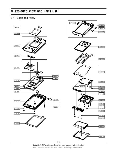
<strong>3.</strong> <strong>Exploded</strong> <strong>View</strong> <strong>and</strong> <strong>Parts</strong> <strong>List</strong>3-1. <strong>Exploded</strong> <strong>View</strong>QCW01QWD01QVO01QFR01QIF01QCK01QFU01QKP01QKP02QME02QLB02QSH01QLC01QCA01QCA02QMP01QME06QAR01QMO01QCB01QME04QBM01QAN02QCR12QFL01QCR12QSC01QHI01QSC14QRE01QCR12QSC13QRF01QAN06QCR04QSC13QMW04QBA01QBA003-1SAMSUNG Proprietary-Contents may change without noticeThis Document can not be used without Samsung's authorization
<strong>Exploded</strong> view <strong>and</strong> Part <strong>List</strong>3-2. <strong>Parts</strong> <strong>List</strong>Location NO. Description SEC CODEQAN02 INTENNA-SGHZ540 GH42-00723AQAN06 MEC-CASE INTENNA FOLDER GH75-08620AQAR01 AUDIO-RECEIVER 3009-001173QBA00 PMO-CASE BATTERY FOLDER GH72-26922AQBA01 BATTERY-880MAH,BLK,MAIN GH43-02253AQCA01 UNIT-MEGA CAMERA GH59-02709AQCA02 UNIT-VGA CAMERA GH59-02710AQCB01 CBF COAXIAL CABLE GH39-00403AQCR04 SCREW-MACHINE 6001-001479QCR12 SCREW-MACHINE 6001-001530QCW01 PCT-COVER CAMERA WINDOW GH72-28463AQKP01 MEC-KEYPAD(OMN/BLK) GH75-09169AQLB02 NDC-BRACKET MP3 KEY GH71-05913AQLC01 LCD-SGHZ540 MODULE GH07-00822AQME02 UNIT-KEY PAD GH59-02667AQME06 UNIT-SPK FPCB GH59-02671AQMO01 MOTOR DC-SGHZ540 GH31-00218AQMP01 PBA MAIN-SGHZ540 GH92-02496AQMW04 MEC-COVER MAIN WIN(VODA) GH75-09036AQRE01 MEC-REAR COVER GH75-08621AQRF01 MPR-TAPE RF HOLE GH74-20208AQWD01 PCT-COVER SUB WINDOW GH72-28461AQSC01 RMO-CAP FOLDER TOP GH73-05894AQSC13 RMO-COVER REAR GH73-05901AQSC14 RMO-COVER FOLDER BOT GH73-05895AQSH01 MEC-BRACKET SHIELD GH75-09118AQBM01 ELA ETC-Z540 BLUETOOTH MODUL GH96-02136AQME04 UNIT-BTFPCB GH59-02750AQFU01 MEC-FOLDER UPPER GH75-08617AQKP02 MEC-KEY FOLD(MP3) GH75-09034AQFL01 MEC-FOLDER LOWER GH75-08618AQHI01 MEC-HINGE GH75-04334DQFR01 MEC-CASE FRONT FOLDER GH75-08619AQCK01 PMO-CAMERA KEY GH72-26932AQIF01 PMO-COVER IF GH72-26917AQVO01 PMO-VOLUME KEY GH72-26931A3-2SAMSUNG Proprietary-Contents may change without noticeThis Document can not be used without Samsung's authorization
<strong>Exploded</strong> view <strong>and</strong> Part <strong>List</strong>DescriptionSEC CODEBAG PE 6902-000378BAG PE 6902-000634CBF INTERFACE-DATA LINK CABLEGH39-00444AADAPTOR-SGHD800 TA(EU)GH44-01060AS/W CD-PC STUDIOGH46-00198AUNIT-EARPHONEGH59-02499ASPRING ETC-BATT LOCKERGH61-00120ALABEL(P)-IMEIGH68-01335DLABEL(P)-WATER SOAKGH68-02026ALABEL(R)-MAIN(EU)GH68-08783AMANUAL USERS-VODA ITALIANGH68-08843ABOX(P)-UNIT(EU NEW)GH69-02908ABOX(P)-SLIP CASE(EU)GH69-03488ACUSHION-CASE(1-2)GH69-03556AMPR-BOHO VINYL LCD CONNGH74-15350AMPR-TAPE MAIN WINDOWGH74-20193AMPR-TAPE LCD MASKING 1GH74-20203AMPR-TAPE LCD MASKING 2GH74-20204AMPR-TAPE INTENNA CABLEGH74-20205AMPR-TAPE FPCB BLUEGH74-20434ACONEGH74-20459AMPR-VINYL BOHO LCD MAINGH74-20460AMPR-VINYL BOHO F/L(S)GH74-20460BMPR-VINYL BOHO LCD SUBGH74-20461BMPR-VINYL BOHO MP3 KEYGH74-20790AMPR-VINYL BOHO MP3 KEYGH74-20790AMPR-TAPE BLUE SHIELDGH74-20844AMPR-CUSHION MP3 KEYGH74-21083AMPR-CUSHION MOTORGH74-21084AMPR-TAPE MIC MASKGH74-21217AMPR-VINYL BOHO SIDE KEYGH74-21328AMPR-SPONGE UPPERGH74-21434AMEC-HANGER(BLK)GH75-08867E3-3SAMSUNG Proprietary-Contents may change without noticeThis Document can not be used without Samsung's authorization
<strong>Exploded</strong> view <strong>and</strong> Part <strong>List</strong>3-<strong>3.</strong> Disassembling Manual12Remove B/T MODULE from the BT connector.1) After remove screw cap with tweezers, Unscrew.2) Remove REAR <strong>and</strong> INTENNA COVER.3) Unscrew from the INTENNA.1) Remove B/T MODULE from the BT connector.2) Remove B/T MODULE from attached to Front withtweezers.1) When you use tweezers, Be careful a damage ofcomponent.1) When you remove the B/T MODULE, Be careful crack<strong>and</strong> damage of the BT MODULE.3 41) Remove LCD Connector <strong>and</strong> INTENNA Connector fromthe PBA.2) Remove PBA from the FRONT ASS'Y.1) Remove INTENNA WIRE Tape with tweezers.2) Remove INTENNA <strong>and</strong> INTENNA WIRE.1) Pay attention to tear of the FPCB.1) When you remove the tape, pay attention to damage2) Pay attention to damage of the wire.of the INTENNA WIRE.2) Be careful h<strong>and</strong>ling INTENNA. (Don't touch intenna pattern.)3-4SAMSUNG Proprietary-Contents may change without noticeThis Document can not be used without Samsung's authorization
<strong>Exploded</strong> view <strong>and</strong> Part <strong>List</strong>5 61) Remove SHIELD CAN <strong>and</strong> KEY PAD from the FOLDER ASS"Y.1) Remove conduction Tape <strong>and</strong> Rubber from the FOLDERASS'Y with tweezers.1) Disjoint KEYPAD <strong>and</strong> SHIELD CAN together.7 81) Using a disassemble stick, Disjoint the Folder like the Photo. 1) After remove screw cap with tweezers, Unscrew.1) When you disjoint the Folder, pay attention to damageof the LCD F-PCB.2) When you use a disassemble stick, Be careful a damageof component.1) When you use a screwdriver, Be careful a damageof component.9101) Disjoint the Folder of the Bottom with tweezers.2) Using a disassemble stick, disjoint the Folder of the Side.1) When disjointing UPPER, pay attention to damage ofthe wire.1) Romove the LCD PROTECTION TAPE with tweezers1) Pay attention to a finger mark <strong>and</strong> dust of the LCD.2) When you use tweezers, Be careful a damage ofcomponent.3-5SAMSUNG Proprietary-Contents may change without noticeThis Document can not be used without Samsung's authorization
<strong>Exploded</strong> view <strong>and</strong> Part <strong>List</strong>11 Lift BRAKET12with tweezers1) Take off the SPK <strong>and</strong> the RECEIVER from the LOWER withtweezers.2) Open the ACTUATOR around the SPK ASS'Y connector.3) After lifting BRAKET with tweezers,remove the SPKASS'Y.1) When you take off the SPK <strong>and</strong> the RECEIVER, pay attentionto damage of the SPK <strong>and</strong> the RECEIVER.2) When disjointing SPK ASS'Y, pay attention todamage of the F-PCB.1) Take off the MOTOR from the LOWER with tweezers.2) Open the ACTUATOR around the CAMERA connector.1) When you take off MOTOR, pay attention to damage ofLCD F-PCB <strong>and</strong> MOTOR WIRE.2) pay attention to damage of CAMERA F-PCB .131) Take off the LCD from the LOWER .2) Take off the MEGA CAMERA from the LOWER.1) When you remove the LCD, pay attention to damage of LCD F-PCB,LCD component, finger mark, dust.2) When you remove the CAMERA, pay attention to damage of CAMERA F-PCB <strong>and</strong> CAMERA.3-6SAMSUNG Proprietary-Contents may change without noticeThis Document can not be used without Samsung's authorization
<strong>Exploded</strong> view <strong>and</strong> Part <strong>List</strong>71) Connect ANT cover with FRONT2) Screw down3) Insert Screw cap at two points1) Take care so that ANT cover do not interfere with Ant wire.2) On screwing down, be careful not to scratch84F-PCB insert5 CAMERAinsert3 MOTOR insert1 LCD insert1) Insert LCD <strong>and</strong> SPK ASS'Y bracket.2) Twist twice MOTOR wire <strong>and</strong> insert MOTOR.3) insert LCD FPCB into F/LOWER hole.4) Insert VGA CAMERA.5) Attach a semocircular Poron sponge on the MOTOR with apinset.2 Bracket insert1) On inserting LCD, be careful for foreign substance.2) Take care that MOTOR wire do not interfere with screw boss.3) Notice that FPCB should not be cracked on inserting CAMERA.3-9SAMSUNG Proprietary-Contents may change without noticeThis Document can not be used without Samsung's authorization
<strong>Exploded</strong> view <strong>and</strong> Part <strong>List</strong>91) Attach a black insulation tape on LCD upper covering parts2) Push <strong>and</strong> insert a receiver into LOWER receiver insertingposition rightly.3) Insert SPK into LOWER SPK position.4) Attach a black insulation tape on LCD lower covering parts.5) Push a receiver wire for wire to avoid putting on F-PCB.1) Attach insulation tapes covering parts perfectly at the right position.→Check tape position with red lines.101) Firstly, connect UPPER end hook with LOWER end hook.2) Be care for foreign substance <strong>and</strong> connect Lower hooks.3) Connect side hooks.1) Notice that foreign substances do not go in.3-10SAMSUNG Proprietary-Contents may change without noticeThis Document can not be used without Samsung's authorization
<strong>Exploded</strong> view <strong>and</strong> Part <strong>List</strong>111) Screw down at four points.2) Insert screw cap at four points.12Insert pushing hinge with wooden pinsetor h<strong>and</strong>1) Insert FOLDER into FRONT passing hole.2) After inserting hinge dummy, assemble pushing hinge on the other part with wooden pinset or h<strong>and</strong>.3) Check folder connection by repeating open <strong>and</strong> close two or three times.3-11SAMSUNG Proprietary-Contents may change without noticeThis Document can not be used without Samsung's authorization
<strong>Exploded</strong> view <strong>and</strong> Part <strong>List</strong>13 141) Insert PBA into FRONT ASS'Y.2) When inserting PBA, put ANT wire at PBA holenear the screw boss hole <strong>and</strong> connect withconnector.1) Connect LCD F-PCB connector.2) Connect B/T Module.1) Be careful not to damage ANT wire.2) Ensure space so that ANT Wire can not be damaged when connecting FRONT with REAR.15 161) After aligning REAR upper hook part with FRONT upperhook part, cover REAR <strong>and</strong> assemble.→ Check the hook connection by pushing the upper partof REAR1) Screw down 4 points.3-12SAMSUNG Proprietary-Contents may change without noticeThis Document can not be used without Samsung's authorization
<strong>Exploded</strong> view <strong>and</strong> Part <strong>List</strong>3-5. LCD KIT assembling Manual11) Attach the black insulation tape on the LCD upper to cover parts completely.→ Attach tape according to red lines.Discription SEC CODE SEC Design quantityTAPE LCD MASKING 1 GH74-20203A 39.7 x 31.6 x 0.08T 1- - - -21) Attach the black insulation tape on the LCDlower to cover parts completely.→ Attach tape according to red lines.Discription SEC CODE SEC Design quantityTAPE LCD MASKING 2 GH74-20204A 39.7 x 11.62 x 0.08T 1- - - -3-13SAMSUNG Proprietary-Contents may change without noticeThis Document can not be used without Samsung's authorization
<strong>Exploded</strong> view <strong>and</strong> Part <strong>List</strong>3-6. Test Jig (GH80-03308A)3-6-1. RF Test Cable(GH39-00397A)3-6-2. Test Cable 3-6-<strong>3.</strong> Serial Cable3-6-4. Power Supply Cable 3-6-5. DATA CABLE 3-6-6. TA3-14SAMSUNG Proprietary-Contents may change without noticeThis Document can not be used without Samsung's authorization
