Chapter 5 Pressure Altimeter - Aircraft Spruce
Chapter 5 Pressure Altimeter - Aircraft Spruce
Chapter 5 Pressure Altimeter - Aircraft Spruce

You also want an ePaper? Increase the reach of your titles
YUMPU automatically turns print PDFs into web optimized ePapers that Google loves.
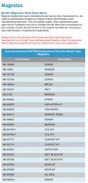
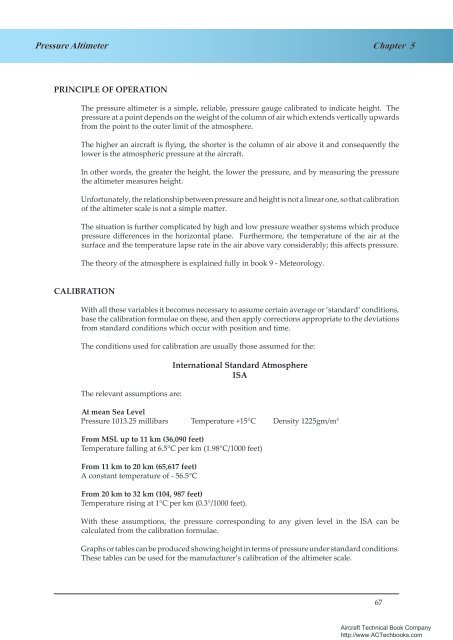
<strong>Pressure</strong> <strong>Altimeter</strong><strong>Chapter</strong> 5SENSITIVE ALTIMETERTEMPERATURE COMPENSATED 'D' SPRINGPOINTERSCAPSULESA SUITABLELINKAGE OFGEARS ANDLEVERSSUBSCALEThe Single Pointer Single<strong>Altimeter</strong> was not accurateenough, and was developedinto the Sensitive <strong>Altimeter</strong>illustrated in Figure 5.2.STATICSUB-SCALESETTING KNOBFigure 5.2 Sensitive <strong>Altimeter</strong>Figure 5.2. A Schematic Diagram of a SensitiveThe principle of operation <strong>Altimeter</strong>. is similar to that of the simple altimeter but there are the followingrefinements:-‣ A bank of two or three capsules gives the increased movement necessary todrive three pointers. These are geared 100:10:1, the smallest indicating 100,000feet per revolution, the next 10,000 feet per revolution and the largest 1,000 feetper revolution.‣ Jewelled bearings are fitted, reducing friction and the associated lag inindications.Note: Some altimeter systems employ “Knocking / Vibrating” devices to help overcome initial inertiaof the internal gear train when transmitting movement from the capsules to the pointers.‣ A variable datum mechanism is built in. This, with the aid of a setting knob,enables the instrument to be set to indicate height above any desired pressuredatum.The variable datum mechanism is used as follows:-The pilot turns the knob until the desired pressure level (say, 1005 mb. appears on a pressuresub-scale on the face of the instrument.As he turns the knob, the height pointers rotate until, when the procedure is completed withthe sub-scale showing the desired 1005, the altimeter indicates the aircraft's height above thispressure level.If for instance the aerodrome level pressure happened to be 1005 mb, the altimeter would bereading height above the aerodrome (and the pilot would have set a ‘QFE’ of 1005 on the subscale).Further details of the procedural uses of the pressure sub-scale are given later in thischapter. The sub-scale setting only changes when the pilot turns the knob. A change in altitudeor surface pressure has no direct effect on the reading of the sub-scale. As the pilot alters thesub-scale setting, the altimeter pointers move, but the design of the mechanism is such thatthe reverse does not apply (for example, during a climb, the pointers rotate but the sub-scalesetting remains unchanged). British altimeters have a sub-scale setting range between 800 to1050 millibars.69<strong>Aircraft</strong> Technical Book Companyhttp://www.ACTechbooks.com
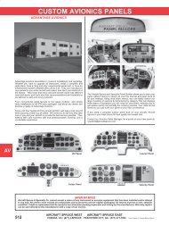
<strong>Chapter</strong> 5<strong>Pressure</strong> <strong>Altimeter</strong>READING ACCURACY8902The simple altimeter is not sensitive, recordingperhaps 20,000ft for each revolution of its singlepointer. The three-pointer instrument gives amuch more sensitive indication of height andchange of height but suffers from the severedisadvantage that it can be easily misread.73645Figure 5.3. A Three PointerFigure 5.3 Three Pointer <strong>Altimeter</strong>Indicating 24,020 feet.Indicating 24,020 ftIt is not difficult for the pilot to make a readingerror of 10,000ft, particularly during a rapiddescent under difficult conditions with a highflight-deck work-load.Accidents have occurred as a result of suchmisreading. Various modifications to thepointers and warning systems have been triedwith the object of preventing this error, includinga striped warning sector which appears as theaircraft descends through the 16,000 foot level.240201 0 1 3Figure 5.4. A Counter PointerFigure 5.4 Counter / Pointer <strong>Altimeter</strong><strong>Altimeter</strong>.The greatest advance has been the introduction ofthe counter-pointer altimeter, illustrated in Figure5.4., which gives a much more positive indicationthan the three-pointer dial drawn in Figure 5.3.With further reference to Figure 5.4., it will berealised that though the digital counters give anunambiguous indication of the aircraft’s height,they give a relatively poor display of the rate ofchange of height.For this reason the instrument also has a singlepointer which makes one revolution per 1000feet, giving the clear indication of change ofheight which is extremely important to the pilot,particularly on the final approach in instrumentconditions.70<strong>Aircraft</strong> Technical Book Companyhttp://www.ACTechbooks.com
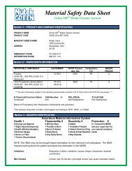
<strong>Pressure</strong> <strong>Altimeter</strong><strong>Chapter</strong> 5EXAMPLES OF ALTIMETERSA Sensitive <strong>Altimeter</strong> Reading 260ft<strong>Altimeter</strong> Reading12,8500 ft or3,917 mElectronic Display fitted to a Boeing 737Fig 5.5 <strong>Altimeter</strong> Types71<strong>Aircraft</strong> Technical Book Companyhttp://www.ACTechbooks.com
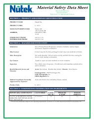
Flight Director Systems<strong>Chapter</strong> 28INTRODUCTIONThe Flight Director System (FDS) was originally developed as an aid used by the pilot duringlanding. It gave a pilot the ability to concentrate on fewer instruments and, as it gave instructionsas to attitude and steering, it reduced the workload on the pilot. As autopilots became moreadvanced the signals produced by the FDS could be coupled to the autopilot allowing it toperform more complex tasks.With a FDS, information about the attitude, heading and flight-path of an aircraft, can beintegrated with navigation information to produce either easy to interpret visual instructionsfor the pilot and / or input to the autopilot, or both.To bring the terminology of FDS and autopilot together it is usual to describe the FDS as having2 “channels”. The first channel is the roll channel, the second is the pitch channel. You willlearn more about channels in the autopilot section.Information for the FDS can come from several possible sources:¾¾¾¾¾¾Pitot-Static system or Air Data Computer (ADC).VHF Nav receiver allowing input from VOR beacons or ILS.Flight Management System, Inertial Navigation / Reference System.The FDS also requires attitude and directional information. On older, electro-mechanicalsystems this would come from the Gyro Magnetic Compass and a Vertical Gyro System. Moremodern aircraft use Inertial Navigation/Reference System (INS / IRS) information in place ofa vertical gyro and will be able to feed the navigation data from these systems into the FDS /Autopilot combination.Fig 1.1 Fig A “typical” 28.1 A “typical” electro-mechanical Flight Director Flight Director System System403<strong>Aircraft</strong> Technical Book Companyhttp://www.ACTechbooks.com
Flight Director Systems<strong>Chapter</strong> 28Primary Flight Display (PFD)The PFD is part of an EFIS (Electronic Flight Instrument System) display and brings all of theinformation required to fly the aircraft onto one display. It has an EADI normally surroundedby speed, altitude, and vertical speed tapes and often a compass display incorporating someminimal navigation information. It also has an area which is used for annunciating flightdirector, autopilot and auto-throttle modes and status.Figure 28.3405<strong>Aircraft</strong> Technical Book Companyhttp://www.ACTechbooks.com
<strong>Chapter</strong> 28Flight Director SystemsElectronic Horizontal Situation Indicator (EHSI)You may already be familiar with the Gyro Magnetic Compass. An HSI is a gyro magneticcompass display with a Course Deviation Indicator (CDI bar), a series of dots representingdeviation in degrees (the scale varies with the type of display) a from / to pointer, a selectedcourse window and a DME display of range. A heading bug is also included. In older systemsthe course selection is done directly on the HSI using an attached knob. The system we will referto uses a remote centralised FD mode control and AP panel called the Autoflight Mode ControlPanel (AMCP or simply MCP). The system we will be referring to also uses a NavigationalDisplay (ND). This, like the PFD, is a more flexible display but is able to show “classical”representations of an HSI.Figure 28.4 HSI DisplayFigure 28.5 EHSI406<strong>Aircraft</strong> Technical Book Companyhttp://www.ACTechbooks.com