Fingerprint Recognition Using Zernike Moments
Fingerprint Recognition Using Zernike Moments
Fingerprint Recognition Using Zernike Moments

Create successful ePaper yourself
Turn your PDF publications into a flip-book with our unique Google optimized e-Paper software.
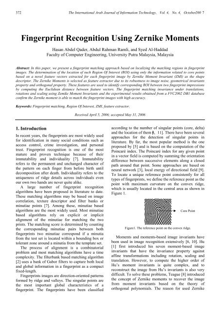
372 The International Arab Journal of Information Technology, Vol. 4, No. 4, October200 7<strong>Fingerprint</strong> <strong>Recognition</strong> <strong>Using</strong> <strong>Zernike</strong> <strong>Moments</strong>Hasan Abdel Qader, Abdul Rahman Ramli, and Syed Al-HaddadFaculty of Computer Engineering, University Putra Malaysia, MalaysiaAbstract: In this paper, we present a fingerprint matching approach based on localizing the matching regions in fingerprintimages. The determination of the location of such Region Of Interest (ROI) using only the information related to core pointsbased on a novel feature vectors extracted for each fingerprint image by <strong>Zernike</strong> Moment Invariant (ZMI) as the shapedescriptor. The <strong>Zernike</strong> <strong>Moments</strong> is selected as feature extractor due to its robustness to image noise, geometrical invariantsproperty and orthogonal property. These features are used to identify corresponding ROI between two fingerprint impressionsby computing the Euclidean distance between feature vectors. The fingerprint matching invariance under translations,rotations and scaling using Zemike Moment Invariants and the experimental results obtained from a FVC2002 DB1 databaseconfirm the <strong>Zernike</strong> moment is able to match the fingerprint images with high accuracy.Keywords: <strong>Fingerprint</strong> matching, Region Of Interest, ZMI, feature extractor.Received April 5, 2006; accepted May 31, 20061. IntroductionIn recent years, the fingerprints are most widely usedfor identification in many social conditions such asaccess control, crime investigation, and personaltrust. <strong>Fingerprint</strong> recognition is one of the mostmature and proven technique because of theirimmutability and individuality [7]. Immutabilityrefers to the permanent and unchanged character ofthe pattern on each finger from before birth untildecomposition after death. Individuality refers to theuniqueness of ridge details across individuals evenour own two hands are never quite alike.A large number of fingerprint recognitionalgorithms have been proposed in literature to date.These matching algorithms may be based on imagecorrelation, texture descriptor and filter banks orminutiae points [7]. Among these, minutiae basedalgorithms are the most widely used. Most minutiaebased algorithms rely on explicit or implicitalignment of the minutiae for matching the twoprints. The matching score is determined by countingthe corresponding minutiae pairs between bothfingerprints two minutiae correspond if a minutiafrom the test set is located within a bounding box ortolerant zone around a minutia from the template set.The process of alignment is a combinatorialproblem and most matching algorithms have a timecomplexity. The filterbank based matching algorithm[2] uses a bank of Gabor filters to capture both localand global information in a fingerprint as a compactfixed-length.<strong>Fingerprint</strong>s images are direction-oriented patternsformed by ridge and valleys. The singular points arethe most important global characteristics of afingerprint. The fingerprints have been classifiedaccording to the number of singular points (core, delta)and the location of them [4, 11]. There have been severalapproaches for the detection of singular points inliterature. By far, the most popular method is the oneproposed by [5] and is based on the computation of thePoincaré index. The Poincaré index for any given pointin a vector field is computed by summing the orientationdifference between successive elements along a closedpath around that point. Some approaches are based onneural network [3], local energy of directional field [9].To locate a unique reference point consistently for alltypes of fingerprints, we define the reference point as thepoint with maximum curvature on the convex ridge,which is usually located in the central area as shown inFigure 1.Core PointFigure1. The reference point on the convex ridge.<strong>Moments</strong> and moments-based image invariants havebeen used in image recognition extensively [6, 10]. Hu[1] first introduced his seven moment-based imageinvariants that have the invariance property againstaffine transformations including rotation, scaling andtranslation. However, to compute the higher order ofHu’s moment invariants is quite complex, and toreconstruct the image from Hu’s invariants is also verydifficult. To solve these problems, Teague [8] introducedthe concept of <strong>Zernike</strong> moments to recover the imagefrom moment invariants based on the theory oforthogonal polynomials. The reason for used <strong>Zernike</strong>
<strong>Fingerprint</strong> <strong>Recognition</strong> <strong>Using</strong> <strong>Zernike</strong> <strong>Moments</strong> 373moments in fingerprint recognition, the image has theinvariance property against image rotation, scalingand translation, which is very desirable for robustfingerprint matching. While the magnitudes of theorthogonal <strong>Zernike</strong> moments are used as rotationinvariantfeatures.<strong>Zernike</strong> moments have been shown to be superiorto the others in terms of their insensitivity to imagenoise, information content, and ability to providefaithful image representation [10]. Zemike moments,have been previously used for other biometrics, suchas face and gait recognition, signature authentication,watermarking, moving recognition, and showed anencouraging performance.In this paper, we define the reference point of afingerprint as the point of maximum curvature in thefingerprint image. <strong>Fingerprint</strong> recognition isgenerally composed of five stages. In the first thefingerprint image is enhanced by means of localhistogram equalization. Furthermore, and in thesecond stage detect the reference point (core point) inthe fingerprint image, and crop from the fingerprintimage a smaller region centered in the referencepoint, called ROI. The ROI is defined in wxw squareshape and it contains sufficient information torepresent the fingerprint.. The third stage involvesfeature extraction by using <strong>Zernike</strong> <strong>Moments</strong>Invariant (ZMI) as feature descriptor, so, each featurevector extracted form each ROI used to represent thefingerprint. Euclidean distance is applies to computethe similarity measure of the fingerprint for featurematching in the fourth stage. The final stage requiresdecision making whether a claimant should beaccepted or rejected.2. PreprocessingBecause there is noise in original fingerprint images,and fingerprint images may be in bad quality, wecannot identify the singular point area efficiently. Inorder to reduce the influence of noise, we preprocessthe input fingerprint images.2.1. Image NormalizationThe objective is to decrease the dynamic range of thegray between ridges and valleys of the image, wenormalize the image to constant mean and variance.Normalization is done to remove the effects of sensornoise and finger pressure difference. I(i,j) denotes thegray value at pixel (i,j). M and VAR are the estimatedmean and variance of the input fingerprint image.N(i,j)=M 0M0VAR xI i j M20( , ) ), ifI ( i,j) MVARVAR x I i j M20( ( , ) ), otherwiseVAR(1)where M 0 and VAR 0 are the desired mean and variancevalues.2.2. Smooth and Histogram EqualizationAfter normalization, we use Gaussian smoothing toreduce the influence of noises, and we usehistogram equalization to make the input fingerprintimage look clear.3. Reference Point Location<strong>Fingerprint</strong>s have many conspicuous landmark structuresand a combination of them could be used forestablishing a reference point. We define the referencepoint of a fingerprint as the point of maximum curvatureof the concave ridges in the fingerprint image. Asummary of reference point location algorithm ispresented below [2].1. Estimate the orientation field O using a window sizeof wxw.2. Smooth the orientation field in a local neighborhood.Let the smoothed orientation field be represented asO’. In order to perform smoothing (low-passfiltering), the orientation image needs to be convertedinto a continuous vector field, which is defined as.(i, j ) cos( O(i, j ))(2)( i,j) sin (2O(, ji ))(3)x2ywhere and , are the x and y components of thex yvector field, respectively. With the resulting vector field,the low-pass filtering can then be performed as./xw/ 2uww/ 2( i , j) W(u,v). ( iuw,vwj)/ 2vw/y/ 2( i,j)yw / 2wx/ 2uw/ 2vw/ 2W(u,v)(4)( i uw, vwj ) (5)where W is a two-dimensional low-pass filter with unitintegral and w x w specifies the size of the filter.Note that the smoothing operation is performed at theblock level. For our experiments, we used a 7x7 meanfilter. The smoothed orientation field at is computed as.O'( i,j)1tan21'( i,j)y (6)'( i,j)x 3. Compute , an image containing only the sinecomponent of O’.
374 The International Arab Journal of Information Technology, Vol. 4, No. 4, October200 7( i, j ) sin( O' ( i, j )).(7)4. Initialize A, a label image used to indicate thereference point.5. For each pixel (i,j) in , integrate pixel intensities(sine component of the orientation field). it’sdesigned to capture the maximum curvature inconcave ridges. Although this to detects thereference point.6. Find the maximum value and assign its coordinateto the reference point.4. <strong>Zernike</strong> <strong>Moments</strong> Invariant<strong>Zernike</strong> moments a set of complex polynomials{V nm (x,y)} which form a complete orthogonal setover the unit disk of x 2 +y 2 ≤1, in polar coordinates [8]the form of the polynomials is:V nm (x, y) =V nm (r,θ)=R nm (r) exp( jmθ )(8)where n is positive integer or zero; m is integerssubject to constraints n-|m| is even, and |m| ≤ n; r =2 2x y is the length of the vector from the originto the pixel (x, y); θ = arctan(y/x) is the anglebetween the vector r and x axis in counterclockwisedirection; R nm (r) is Radial polynomial defined as:Rnm( r)( n|m|)/ 2s0s( 1)( n s)!rn| m | n| m | s! s! s! 2 2 n2s(9)The two-dimensional <strong>Zernike</strong> moment of order nwith repetition m for function f (x,y) is defined as:n 1Z =nm f(x,y)V * (x,y)dxdy nm unitdisk(10)where V * nm (x, y)= V n,-m (x, y).To compute the <strong>Zernike</strong> moment of a digitalimage, we just need to change the integrals withsummations:n A =1nm f ( x,y)V*( x,y),nm2 2where x y 1.xy(11)The defined features of <strong>Zernike</strong> momentsthemselves are only invariant to rotation. To achievescale and translation invariance, the image needs tobe normalized first by using the regular <strong>Zernike</strong>moments.The translation invariance is achieved by translatingthe original image f(x,y) to f ( x x,yy ) ,where x m m and y m m .10 0001 00In other words, the original image’s center is movedto the centroid before the <strong>Zernike</strong> moment’s calculation.Scale invariance is achieved by enlarging or reducingeach shape so that the image’s 0th regular moment m ' 00equals to a predetermined value β. For a binary image,m equals to the total number of shape pixels in the00image, for a scaled image f( α x, α y) , its regularmoments m ' = α pq2m , m is the regular momentspq pq pqof f(x, y).Since the objective is to make m ' = β, we can let00α= m . by substituting α= m into m ' , we000000can obtain m ' =α 2 m =β.00 00The fundamental feature of the <strong>Zernike</strong> moments istheir rotational invariance. If f(x, y) is rotated by anangle , then we can obtain that the <strong>Zernike</strong> momentZ of the rotated image is given bynmZ'nm Znme( jm)(12)Thus, the magnitudes of the <strong>Zernike</strong> moments can beused as rotationally invariant image features.A fingerprint recognition system is a one-to-onematching process. It matches a person’s claimed identityto enrolled pattern. There are two phases in our system:enrollment and verification. Both phases comprise frompreprocessing for fingerprint image and detect and cropthe ROI, and extract the feature vectors invariant byZMI features extraction. However, verification phaseconsists of an additional stage, for calculating thesimilarity matching of the fingerprint. At the enrollmentstage, a set of the template images represented by ZMIfeatures is labeled and stored into a database. At theverification stage, an input image is converted into a setof ZMI features, and then is matched with the claimant’sROI fingerprint image stored in the database to gain thesimilarity measure. Euclidean distance metric is appliedto calculate the similarity between the two featurevectors. Finally, the distance score is then comparedwith a threshold value to determine whether the usershould be accepted.5. Experimental ResultsExperimental studies are carried out on the Database ofFVC2002. We take six impressions of 100 differentfingers, yielding 600 fingerprint images in the database.Among the six images from each user, three are selected
<strong>Fingerprint</strong> <strong>Recognition</strong> <strong>Using</strong> <strong>Zernike</strong> <strong>Moments</strong> 375for training while other three are used for testing. Wehave chosen the ZMI of order 10 for featureextraction, the 36 feature vector invariant to representeach ROI area. The ROI is then used for featureextraction. The extracted ROI of the fingerprint isprocessed by ZM feature vector extractors to obtainthe most discriminating features from the fingerprintfor recognition task.To investigate the performance of ROI, therecognition rate is displayed in Table 1. Experimentalresult shows that ROI is able to achieve correctrecognition rate for ROI a 92.89% is achieved usingthe Euclidean distance. The system performance canbe evaluated by using Equal Error Rate (EER) whereFAR=FRR.Table 1. Testing result of recognition rate.TypeCorrect <strong>Recognition</strong> RateFAR(%) 7.108FRR(%) 7.151TSR(%) 92.892EER(%) 7.130Figure 2 shows a threshold value is obtained basedon Equal Error Rate criteria where FAR=FRR.Threshold value of 0.4132 is achieved when the FARand FRR are set to 7.108% and 7.151% respectively.False Acceptance Rate100908070 FARFRR60504030201000 0.1 0.2 0.3 0.4 0.5 0.6 0.7 0.8 0.9 1ThresholdFigure 2. Plotted FAR-FRR graph to obtain threshold.The overall matching performance can bemeasured by a Receiver Operating Characteristic(ROC) curve, which plots FRR against FAR atdifferent operating points (distance threshold) Figure3 illustrates the ROC curve.F R RPlot of Receiver Operating Curve for (ROI) Area10090807060504030201000 10 20 30 40 50 60 70 80 90 100FARFigure 3. ROC based on testing databaseBased on the ROC plotted above in Figure 5shows the ZMI perform well as feature descriptors onfingerprint images, this vindication of the orthogonalityadvantage.Orthogonality property of ZM is able to elicit theunique fingerprint attributes into each order momentwith minimum information redundancy.6. ConclusionsThe idea of implementing <strong>Zernike</strong> moment as fingerprintfeature extractors is that they posses a useful rotationinvariance property. The new feature vectors are rotationand translation invariant and capture more globalinformation on fingerprint ridges and furrows pattern. Inthis paper, fingerprint image recognition has beendeveloped by applying a novel ZMI descriptor veryvaluable in applications of image understandings. <strong>Using</strong>our feature vector robust to transformation and noise,and the reference point feature is computed efficiently,this conclusion is expected to extend to other momentsfamily.References[1] Hu M. K., “Visual Pattern <strong>Recognition</strong> by MomentInvariants,” IRE Transaction Information Theory,vol. IT-8, no. 2, pp. 179-187, 1962.[2] Jain A. k., Prabhaker S., Hong L., andPankanti S., “Filterbank-Based <strong>Fingerprint</strong>Matching,” IEEE Transactions on ImageProcessing, vol. 9, no. 5, pp. 846-859, 2000.[3] Kamijo M., “Classifying <strong>Fingerprint</strong> Images<strong>Using</strong> Neural Network: Deriving theClassification State”, in Proceedings of theInternational Conference on Neural Network,vol. 3, pp. 1932-1937, 1993.[4] Karu K. and Jain A., “<strong>Fingerprint</strong> Classification,”Pattern <strong>Recognition</strong>, vol. 29, no. 3, pp. 389-404,1996.[5] Kawagoe M. and Tojo A., “<strong>Fingerprint</strong> PatternClassification,” Pattern <strong>Recognition</strong>, vol. 17, no. 3,pp. 295-303, 1984.[6] Khotanzad A. and Hong Y., “Invariant Image<strong>Recognition</strong> By <strong>Zernike</strong> <strong>Moments</strong>,” IEEETransactions on Pattern Analysis MachineIntelligent, vol. 12, no. 5, pp. 489–497, 1990.[7] Maltoni D., Maio D., Jain A.K., and Prabhakar S.,“Handbook of <strong>Fingerprint</strong> <strong>Recognition</strong>,” Springer-Verlag, New York, 2003.[8] Mukundan R. and Rmakrishnan K. R., “<strong>Moments</strong>Functions in Image Analysis Theory andApplications,” World Scientific Publishing,Singapore, 1998.[9] Perona P., “Orientation Diffusions,” IEEETransactions on Image Processing, vol. 7, pp. 457-467, 1998.[10] The C. H. and Chin R. T., “On Image Analysis bythe Methods of <strong>Moments</strong>,” IEEE Transactions on