User's Manual - IngMar Medical
User's Manual - IngMar Medical
User's Manual - IngMar Medical

You also want an ePaper? Increase the reach of your titles
YUMPU automatically turns print PDFs into web optimized ePapers that Google loves.
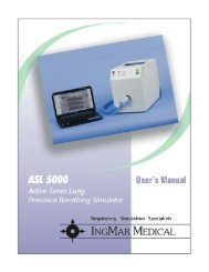
INGMAR MEDICAL, LTD.P. O. Box 10106Pittsburgh, PA, 15240(412) 441-8228(800) 583-9910support@ingmarmed.comwww.ingmarmed.com© <strong>IngMar</strong> <strong>Medical</strong>, 1998-2008, All Rights ReservedSubject to modifications without noticePart No. 20 00 200Printed in the U.S.A.Adult/PediatricDemonstrationLung Model<strong>User's</strong> <strong>Manual</strong>
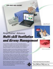
Intended UseThe <strong>IngMar</strong> <strong>Medical</strong> Adult/Pediatric Demonstration LungModel has been developed to assist respiratory care practitioners,particularly education coordinators, in their efforts• to demonstrate various ventilator functionsand features• to educate "hands on" about ventilation topics.The device is an easy-to-operate and reliable tool wherever a"live" demonstration is considered the choice over purelywritten educational material or computer assisted simulation.If this product is not used as instructed, the safety protectionprovided may be impaired.WARNINGAlways follow the Operating Instructions of yourventilator when checking for safety featues andperformance before use.Use of the lung model is not intended to substitutefor manufacturer prescribed texts and procedures.showing with option 24 00 000 (pressure gauges) andoption 26 00 000 (PMG 3000 module).A/P Demo Lung Model Operating Instructions Page 8 of 40 INGMAR MEDICAL, LTDA/P Demo Lung Model Operating Instructions Page 9 of 40 INGMAR MEDICAL, LTD
1. Description1.1 OverviewThe basic <strong>IngMar</strong> <strong>Medical</strong> Adult/Pediatric DemonstrationLung Model is a passive lung simulator for simulating pediatricand adult patients. It complements the <strong>IngMar</strong> <strong>Medical</strong> NeonatalLung Model that is available for education regardingneonatal ventilators. With the addition of our SpontaneousBreathing Module (SB 2000), it becomes an active lung modelwith spontaneous tidal volumes of up to 600 cm 3 .The Adult/Pediatric Lung Model consists of a two-bellowcompliance that is ventilated through valves representingresistances and leaks. The bellow and valve assembly iscontained in an aluminum case with lid with dimensions ofapproximately 8.5 x 12.5 x 6 inches weighing less than 15 lbs.The simulator is operated pneumatically and does not requireany electrical connections in its base configuration.1.2 FeaturesEach compartment represents a maximum lung volume ofapproximately 1 L. For each compliance, resistance can be setindependently and may be varied from 5 to 50 cmH2O/L/s (5,15, 50 with standard orifices at 20 L/min).Compliance can be varied in the range of 40 to 17 mL/cmH2O(40, 30, 20, 17) for each compartment. In addition, a non-linearitymay be introduced to simulate lung overdistention, withthe additional elastance engaging at 1/3 L for both bellows.Leak rates may be varied from 5 L/min at 10 cmH2O toA/P Demo Lung Model Operating Instructions Page 10 of 40 INGMAR MEDICAL, LTD25 L/min at 40 cmH2O (for exact relationship between pressureand leak, see diagrams under 7. Data). One leak parameterrepresents a leak caused by a pneumothorax-type rupturein the lung (compartment leak), the other parameter adjusts anET-tube leak (leak before resistance).The overall diagram for the simulation looks like this:Fig. 1Resistances and leaks are set with rotary knobs that feature 90ºclick stops for different settings. Compliances are set byengaging torsion springs with easy to operate grip latches.1.3 OptionsVent. R L-ETR 1 R 2C 1 C 2R L-CP 1 P 2System pressure can be measured via optional analog pressuregauges (-10 to 100 cmH2O) at the patient connector (airwaypressure), and at each compliance (lung pressure).The PMG 3000 pulmonary mechanics graphics option allowsto visualize respiratory mechanics as real-time data.Our Spontaneous Breathing Module (SB 2000) provides consistentspontaneous breathing for triggering and intermittentbreaths in assisted ventilation modes.A/P Demo Lung Model Operating Instructions Page 11 of 40 INGMAR MEDICAL, LTDP 0
2. ApplicationsThe following section gives some examples of applicationswhere the <strong>IngMar</strong> <strong>Medical</strong> Adult/Pediatric Lung Model maybe used. These are intended as suggestions rather than acomprehensive listing of all potential applications.2.1 Ventilator Functions2.1.1 Flow/Volume MonitoringUsing an adjustable lung model is particularly helpful forteaching about ventilators capable of monitoring flow andvolume (or are connected to a device that performs thisfunction). When the ventilator is connected to a (simulated)patient, the actual values of tidal volume VT, minute ventilation*, and airway leaks can be made visible and provide aguideline that is invaluable in clinical practice. With the lungmodel, it is possible to simulate conditions influencing aboveparameters, such as compliance, resistance, and leak.2.1.2 WaveformsWith the lung model, different effects of the settings of a ventilatormay be studied. If your ventilator is equipped with areal-time waveform display, or you have our PMG 3000 Moduleinstalled and operating, the different settings of complianceand resistance will exhibit characteristic waveforms forpressure, flow and volume.2.1.2.1 Pressure waveformsWith the setting of Resistance to «1» (standard) and complianceto «1» ("no spring", 40 mL/cmH2O) a characteristic waveformpattern will be produced according to the ventilator inspiratorytime, flow, and pressure limit (see Fig. 2 for an example)PressurePressure Waveforms, IFig. 2TimePressure Waveforms, IITimeWith increased resistance, initial ramp steepness is decreasedsince it depends, in its initial slope, on resistance of the ventilatedsystem (being determined by system compliance onlytowards the end of the active inspiratory phase). At this point,flow going into the lungs is limited rather by resistance than bycompliance in the equation of motion:PressurePaw=1/C x V + R x *A/P Demo Lung Model Operating Instructions Page 12 of 40 INGMAR MEDICAL, LTDA/P Demo Lung Model Operating Instructions Page 13 of 40 INGMAR MEDICAL, LTD
In cases where resistance is different between the two compartments(represented by different settings of resistance valves forthe two bellows), the effects can be studied first individuallyand then in combination. Extremely different parameters resultin a "Pendelluft" effect that is a process of equilibration betweenthe two compartments. It is visualized best during anextended inspiratory hold set for the ventilator. The effects ofnot allowing for sufficient time for equilibrium, namely veryuneven distribution of ventilation between the compartments,can, of course, be simulated as well.2.1.2.2 Flow WaveformsFlow is another parameter frequently visualized on ventilatorgraphics screens. A flow waveform can, e.g. tell the therapistwhether exhalation is complete or whether air trapping hasoccurred with particular ventilator settings. This is indicatedby flows that are not zero at the end of expiration, immediatelybefore the next inspiratory cycle forces more air into the lungs.With a lung model, changing patient conditions responsible fordeveloping air trapping can easily be recreated, e.g. byincreasing resistance substantially. With air trapping, theaffected bellow of the model will not have returned to itsclosed position at the end of expiration. Other effects to bestudied are peak flows versus lung resistance.2.1.3 Ventilation in the Presence of LeaksThe <strong>IngMar</strong> Lung Model provides two types of simulatedleaks. With the left leak valve, a leak at the ET-tube is simulated( R L-ET ). The right leak valve controls a bellow leak in theright compartment. The difference between these two types ofleaks is that an ET-tube leak affects both compartments simultaneously,while a bellow leak may become responsible forseverely uneven filling of lung compartments. From Fig.1 (seepage 7) it becomes clear that another difference is the resistancelocated between the ventilator and the leaking compartmentin case of a bellow leak. Depending on its size, this leakmight have a much less noticeable effect on the ventilator.For relationship between pressure and leakage flow throughthe different orifices provided, see section 7. Data.2.1.4 Synchronized VentilationThe <strong>IngMar</strong> <strong>Medical</strong> Adult/Pediatric Lung Model provides aneasy way to simulate spontaneous inspiration. In order toinitiate a triggered ventilator breath, the user simply has topull slightly on the rubber bellow lid knobs. The ventilatorresponse can be felt and judged both in terms of delay andforce necessary to trigger a response.A/P Demo Lung Model Operating Instructions Page 14 of 40 INGMAR MEDICAL, LTDA/P Demo Lung Model Operating Instructions Page 15 of 40 INGMAR MEDICAL, LTD
3. Operation3.1 Preparing for Operation1 Place the Adult/Pediatric Lung Model on a flat surfacewithin easy reach of the ventilator circuit.2 Make sure that:• supporting surface is appropriate for load (15 lbs)• all knobs intended to be used are within reach forthe instructor.3 Unlatch lid and prop up.• Make sure that pressure gauges can be viewedby students.3 Alternatively, remove case lid.• Disconnect pressure gauge lines by twistingconnectors below gauges counterclockwise• Pull lid prop rod from lid (gently move to left afterclosing lid approximately half way.• Pull both L-shaped hinge securing pins outwardswith your finger and pull lidoff its hinges.4 Connect ventilator circuit wye to 15 mm ISO port on theleft side of the simulator case.If the type of wye used has a tendency to kink hoses,consider using an elbow to accomodate an angleA/P Demo Lung Model Operating Instructions Page 16 of 40 INGMAR MEDICAL, LTD5 Preset parameters for the topic of instruction to becovered (see 2. Application).6 Verify simulator operation by pressurizing bellows andchecking for leak.●●• Engage «no. 2» spring on both bellows• Set leaks to «0».CAUTIONVerify that no active humidifier is placed in the circuit.The device is not designed for use with humidified air.• Set resistance to «1» on first bellow, to «0» on second.• Apply approximately 50 cmH2O pressure using themanual breath function of the ventilator (ventilator inIMV mode with lowest rate.When bellow has expanded fully, turn resistance ofbellow to «0» (R=∞) and release pressure from ventilator.Observe bellow. During the next few seconds, bellowshould not move, indicating there are no leaks.• Repeat procedure for second bellow accordingly.If leak is detected, refer to section 6. Troubleshooting.Set parameters according to the intended subject ofinstruction. The device is now ready for demonstrations.A/P Demo Lung Model Operating Instructions Page 17 of 40 INGMAR MEDICAL, LTD
3.2 Changing Lung Model Parameters3.2.1 ComplianceCompliance is adjusted individually for each bellow withtorsion springs that can be individually engaged to alter theopening force for the bellows.NOTE: Spring settings should only be changed while bellowsare not moving and in their closed position.For resulting compliances (approximate values), please refer totable below:Spring Compliance Spring color:No springSpring no. 1C = 40C = 30per bellowper bellow yellowSpring no. 2Springs no. 1 + 2C = 20C = 17per bellowper bellowblueyellow + blueSpring no. 3 C = +20 active at 250 mL redSpring no. 3 is used to simulate lung overdistension and is activatedat preset tidal volume of 250 mL.1 Engaging a spring:In order to engage a spring, first verify that the respectivegrip latch is fully open (yellow pointer in 11 o'clock position).• Turn knob (1, 2, or 3) clockwise and tighten.• Verify visually that spring is engaged when bellowis opened up (yellow pointer in 4 o'clock position).2 Disengaging a spring• Turn knob (1, 2, or 3) counterclockwise until pointerindicates that pawl has turned (yellow pointer in11 o'clock position).• Verify visually that spring is disengaged whenbellow is opened up.3.2.2 ResistanceResistance is adjusted with the outer knobs on the instrumentcase, individually for each bellow.Fig. 3Settings are labeled «OFF» and «1» through «3» representingresistance values according to the table on the next page(user exchangeable, refer to section 5. User Modifications):OFF R = ∞ compartment OFF12R = 10R = 15standard resistance4 mm orifice3 R = 50 3 mm orificeValues may be changed during operation. Resistances are thesame for the respective settings of both compartments.A/P Demo Lung Model Operating Instructions Page 18 of 40 INGMAR MEDICAL, LTDA/P Demo Lung Model Operating Instructions Page 19 of 40 INGMAR MEDICAL, LTD
3.2.3 LeakTwo different types of leaks can be simulated with the <strong>IngMar</strong><strong>Medical</strong> Adult/Pediatric Demonstration Lung Model,- an ET-tube leak, and- a lung leakage in one compartment.While an ET-tube leak affects both compartments and islocated before the simulated airway resistance, lung leakage isintended to show the effect of a pneumothorax (please refer toscheme on page 7).The left center knob on the instrument case operates the ETtubeleak, the right center knob adjusts a leak in the second(right) bellow assembly. For the relationship between pressureand leakage flow please refer to the respective diagram insection 9. Data.●Fig. 4Setting an ET-tube leak• Set left center knob to either «1», «2», or «3» to simulatea small, medium, or large ET-tube leak, respectively.• To turn leak off, set dial to OFF.A/P Demo Lung Model Operating Instructions Page 20 of 40 INGMAR MEDICAL, LTD●Setting a compartment leak• Set right center knob to either «1», «2», or «3» to simulatea small, medium, or large leak, respectively.• To turn leak off, set dial to «OFF».3.3 Obtaining System Pressure InformationIf the pressure gauge option is installed, both patient wyepressure (center gauge) and actual lung pressure for eachcompartment (outside gauges) are registered. If this option isnot included, use external pressure gauge for measuring.3.3.1 Pressure Measurement with Pressure Gauge Option1 Verify proper connection of lid-mounted pressure gaugesto instrument with subminiature quick connects . (Turnclockwise over click to engage, counterclockwise to disengage.)2 Set maximum pressure recording pointer manually to 0(on all gauges).3 Read maximum pressures.• Lung pressures on left-/right-hand gauges• Airway pressure on center gauge.NOTE: Lid with pressure gauges may be removed from casefor better visibility during instruction. Connecting pressurelines will then have to be extended.(See section 5. User Modifications").A/P Demo Lung Model Operating Instructions Page 21 of 40 INGMAR MEDICAL, LTD
3.3.2 Pressure Measurement with External Pressure GaugesIf the pressure gauge option is not installed, use externalpressure gauges to take system pressure. Gauges with a rangeof -10 to 80...100 cmH2O are recommended.WARNINGVerify that pressure gauges used are suitable for usewith oxygen ("oxygen clean") if circuit is going to beventilated with elevated O2 concentrations.Connection of gauges is made most conveniently through therespective sub-miniature quick connect ports. The necessaryconnector-halves can be ordered as part no. 24 00 009.1/8 inch ID tubing is recommended for connecting pressuregauges to the instrument. Alternatively, you may also usepressure line extension set 24 00 010 (extends lines 3 feet)For obtaining accurate pressure measurements, followpressure gauge Instructions for Use.4. Pulmonary Mechanics Graphics Option(PMG 3000)The PMG 3000 option for the Adult/Pediatric Lung Model isan integrated flow monitoring system for displaying pulmonarymechanics data of the simulated patient in real time andoffers a multitude of features that are designed to enhanceteaching about patient-ventilator interaction.With two maintenance-free fixed orifice sensors located at theairway and in one lung branch the system is able to showdifferences between what a ventilator is able to "see" of apatient and actual conditions inside the lungs. It is the onlysuch system available for a lung simulator that is capable ofdelivering accurate flow and volume information under allpossible simulated conditions, including leaks.The battery-operated module works with a regular MS-DOSPC (386 or better) through a serial port (RS 240) connection anduses the PC screen for displaying waveforms, loops and up totwenty different respiratory mechanics parameters.If your Adult/Pediatric Lung Model is equipped with thePMG 3000 Option, please refer to the separate operatinginstruction manual that covers operation of the hard- andsoftware for this product.Please contact us if your system does not have this optioninstalled and you are interested in retrofitting. The modulardesign of our lung simulator system allows for easy upgradingat any time.A/P Demo Lung Model Operating Instructions Page 22 of 40 INGMAR MEDICAL, LTDA/P Demo Lung Model Operating Instructions Page 23 of 40 INGMAR MEDICAL, LTD
5. Spontaneous Breathing Module(SB 2000)The Spontaneous Breathing Module 2000 is the latest additionto <strong>IngMar</strong> <strong>Medical</strong>'s Adult/Pediatric Lung Model System.It is the answer to the need of every respiratory care instructorto incorporate patient spontaneous breathing into the demonstrationsof advanced ventilator modes. It has been designed tofit inside the regular A/P Lung Model in order to preserveportability and ease of use of the system. It does not require asecond ventilator as a "spontaneous breather ventilator" and isfully compatible with our Pulmonary Mechanics Graphics(PMG 3000) Module.Powered from a wall-mount power supply, its functions areoperated with hand-held controller unit that allows you to selectbreath rate, tidal volume, and peak flow.Please contact us about retrofitting if your system does nothave this option installed. The modular design of our lungsimulator system allows for easy upgrading at any time.5.1 OverviewThe SB 2000 module is comprised of three components:• A servo motor drive unit integrated into theAdult/Pediatric Lung Model• A handheld controller unit• A universal input wall-mount power supply(shared with our PMG 3000 system if both optionsare installed).The SB 2000 motor drive consists of a precision DC-gearmotorwith encoder for position servo control and a lift arm for movingthe lung simulator bellows. Please note that the bellows arealways free to be lifted by internal pressure (from a ventilator)beyond the point of movement defined by the SB 2000. A homeswitch integrated into the motor drive unit will provide informationabout the home position to which the lift arm returnsafter operation.CAUTIONAlways verify that the lift arm is in its home position beforeclosing the lid of the lung simulator. Forcing the liftarm down with the bellows can result in damage to thegears of the motor drive unit!A/P Demo Lung Model Operating Instructions Page 24 of 40 INGMAR MEDICAL, LTDA/P Demo Lung Model Operating Instructions Page 25 of 40 INGMAR MEDICAL, LTD
The hand held unit includes all SB 2000 controls.RUNBPMVt/Vtmax(%)*/* max(%)OffsetSB 2000Spontaneous Breathing ModuleING MAR MEDICALFig. 5The power supply is the same as for our PMG 3000 option andis shared with the PMG 3000 if both options are installed.It is a universal input wall-mount charger/supply that can bedelivered with the appropriate prongs for the electric system ofmost countries in the world.Note: For use of the SB 2000, the power supply needs to beplugged in. The option is not powered through rechargeablebatteries as is the PMG 3000 systemSpont. breath rate (1 ... 60 BPM)Relative tidal volume(100% represents approx. 600 cm 3Relative peak flow(100% represents approx. 60 L/min)Offset adjustment for elevated startingpoints (PEEP applied to bellows)Display for parameters and runtimeworkload valuesRun simulationRUN indicator LEDAdjust parametersSelect parameters5.2 SB 2000 OperationTo operate the SB 2000, first make the electrical connections:1 Insert connector from SB 2000controller into receptacle on the leftside of the lung simulator.2 Plug DC connector from wallmountpower supply intoreceptacle below SB 2000 connector.●Connect power supply toline voltage.SB 2000ControllerInput:----15 V± 5%500 mAFig. 6The LED-Display on the controller unit will light up and youwill hear the motor moving to its home position.By pushing the «Select» key, you can choose a parameter to beadjusted. The green indicator LED next to the selected parameterwill be lit.Adjustments to parameters are made with the « » and « »keys.Please refer to the table on the following page for adjustmentranges and increments.A/P Demo Lung Model Operating Instructions Page 26 of 40 INGMAR MEDICAL, LTDA/P Demo Lung Model Operating Instructions Page 27 of 40 INGMAR MEDICAL, LTD
Parameter Unit Min. Max. IncrementofAdjustmentBreath rate BPM1 601Tidal volume*Flow**OffsetSpontaneous breathing begins when the «Start/Stop» key ispressed.5.2.1 Parameter CompatibilityCertain combinations of parameters are beyond the capabilitiesof the system, e.g. a breath rate of 60 BPM with a tidal volumeof 100% (= 600 cm 3 ). In such cases, the display will blink withthe message "Set" after the «Start/Stop» key has been pressed.This indicates that a different combination of parameters needsto be selected.●●●Vt/Vtmax %*/*max %Vt/Vtmax %* !00% tidal volume represents approximately to 600 cm 3** 100% flow represents a peak flow of 55 to 60 L/minPress the «Start/Stop» key again to halt the simulationMake your new parameter selectionPress the «Start/Stop» key again to start.Repeat procedure if necessary.1020101001001001515.2.2 Tips for OperationThe waveform created by the SB 2000 module is determined bythe geometry of the lever system and has been designed tocreate a decelerating flow pattern. Please refer to the Datasection (9.5) for a sample flow and volume tracing using theSB 2000. Small spontaneous breaths are used to demonstratethe trigger response of a ventilator, larger breaths serve toshow the interaction between patient and ventilator in assistedventilation modes such as pressure support or SIMV.When only single-bellow operation is desired, the unusedbellow must be turned off in a raised position in order to notinterfere with the SB 2000 operation. Otherwise a blinking"StL" (= stall) message is generated by the system and themotor will be stopped in order to avoid damage due to overheating.In this case:●●●Press the «Start/Stop» key to halt the simulationRemove the obstructionPress the «Start/Stop» key again to start.Stall protection may also be activated under extreme ventilatorsettings that do not allow enough flow into the system toaccomodate a spontaneous breath. In this case:●●●Press the «Start/Stop» key to halt the simulationAdjust ventilator settingsPress the «Start/Stop» key again to start.A/P Demo Lung Model Operating Instructions Page 28 of 40 INGMAR MEDICAL, LTDA/P Demo Lung Model Operating Instructions Page 29 of 40 INGMAR MEDICAL, LTD
5.3 End of Operation for the SB 2000 ModuleVerify that the bellow lift arm is in its home position. If this isnot the case, perhaps because power had been removed duringa simulation run, briefly reconnect power to allow the systemto reach home position.CAUTIONAlways verify that the lift arm is in its home positionbefore closing the lid of the lung simulator. Forcing thelift arm down with the bellows can result in damage tothe gears of the motor drive unit!You may then disconnect the controller unit from the lung simulator.Lightly apply pressure to the connector at the top andbottom to disengage latch.CAUTIONDo not forcefully pull connector from simulator.This will result in damage to the connector!Always properly disengage latch to remove connector.If your system is equipped with the PMG 3000 option, it isrecommended to leave the power supply connected to chargethe batteries of that system if it is still being used. Otherwise,disconnect power supply from simulator and wall outlet.6. Cleaning and Care6.1 CleaningThe instrument should not require specific cleaning duringroutine use. It is not intended to form part of a sterile patientcircuit and can therefore not be sterilized. The outer surface ofthe instrument case may be wiped off with a damp cloth usinga mild detergent.6.2 StorageStore instrument in a cool and dry place. Rubber componentsmay age prematurely if exposed to heat. Use padded nyloncase (option 25 00 000) for storage if available.6.3 Precautions During TravelCAUTIONDo not immerse instrument in cleaning or disinfectingsolutions. Moisture inside the bellow system should beremoved promptly by ventilating instrument with dry air.CAUTIONAlways leave bellows open (Resistance set to 1, 2, or 3)when exposing instrument to ambient pressure fluctuations,e.g. during air travel. Otherwise, damage to pressuregauges due to excessive pressure might result.Always use care and diligence as with any other technicalinstrument to prevent physical damage.A/P Demo Lung Model Operating Instructions Page 30 of 40 INGMAR MEDICAL, LTDA/P Demo Lung Model Operating Instructions Page 31 of 40 INGMAR MEDICAL, LTD
7. User Modifications7.1 Resistance and Leak ModificationsUsers may want to modify the preset values of resistances andleaks by inserting non-standard orifices in the respectivevalves. See section 7. Data for effect of other than standardorifices used in valves.In order to exchange orifices, follow these steps:1 Open instrument lid2 Unscrew nylon hex cap screw from the respective valveand orifice channel to be modified (use 3/8" hex wrench,not supplied, if screws were tightened using a wrench). Becareful not to damage o-ring washer.3 Extract orifice screw with 3/8" hex wrench.4 Screw new orifice screw into channel as far as it will goand tighten lightly.5 Hand-tighten nylon hex cap screw.Note relationshipof orifice channelsand valve settings3 2 121 37.2 Extending Pressure Gauge LinesPressure gauge lines may be extended to accomodate pressuregauges set up separately from the lung model. Use extensionset 24 00 010 (3 lines 3 feet each) to conveniently extend linesusing the quick connect system installed in the model.Follow these steps to extend lines:1 Disconnect lines at pressure gauges by turning quickconnectors counterclockwise so bajonet mounts snap off.2 Connect extension line connectors with correct endsfacing pressure source and gauge connection point.3 Verify proper function by visual inspection (gaugesconnected to correct pressure source?).NOTE: You can also use the Adult/Pediatric Lung Model withCO2 monitoring systems by bleeding in CO2 through the pressuregauge lines. Adjusting a flow meter to a few hundredcm 3 /min will render quite realistic CO2 waveforms. Pleasecontact <strong>IngMar</strong> <strong>Medical</strong> for a special CO2 line adapter kit.NOTE: The standard resistance orifice (lowest possibleresistance setting) cannot be exchanged.A/P Demo Lung Model Operating Instructions Page 32 of 40 INGMAR MEDICAL, LTDA/P Demo Lung Model Operating Instructions Page 33 of 40 INGMAR MEDICAL, LTD
8. Troubleshooting8.1 LeakageIf there seems to be unappropriate leakage of a bellow. firstverify that leak valves are in closed position. If leak persists,turn leak and resistance knobs once 360° to reset internal valveo-rings. Also check free movement of knobs (damage?).8.2 SpringsIf compliance settings seem not to correspond to springsengaged, verify that all respective springs are activated appropriately.If a spring leg has not been pulled up by its grip latchpawl, open grip latch almost fully (continue opening severalturns after pointer has indicated pawl has turned into 11o'clock position). Afterwards, tighten spring leg again byturning knob clockwise. Visually inspect by closely looking atmovement of spring leg with opening of bellow.8.3 SB 2000 ModuleIf operation stops during a simulation, it is most likely relatedto a stall condition. Check the display for the "StL" messageand proceed as described in 5.2.2.If spontaneous breathing does not begin when the «Start/Stop» key is pressed, either incompatible parameter settingshave been chosen ("Set"-message on display) or a a stall conditionis the cause.A/P Demo Lung Model Operating Instructions Page 34 of 40 INGMAR MEDICAL, LTD A/P Demo Lung Model Operating Instructions Page 35 of 40 INGMAR MEDICAL, LTD
9.2 Resistance Versus Flow for Resistance Orifices1009.3 Flow Versus Pressure for Leakage Orifices3500030000Resistance [cmH2O/L/min]10Flow [mL/min]25000200001500010000500010 10000 20000 30000 40000Flow [mL/min]00 5 10 15 20 25 30 35 40 45 50 55 60 65 70Pressure [cmH2O]4 mm orifice, pos.no. 23 mm orifice, pos.no. 3No orifice, pos. no. 11.5 mm orifice, pos.no. 12.5 mm orifice, pos.no. 31.8 mm orifice, pos. no. 2A/P Demo Lung Model Operating Instructions Page 36 of 40 INGMAR MEDICAL, LTDA/P Demo Lung Model Operating Instructions Page 37 of 40 INGMAR MEDICAL, LTD
9.4 Volume Versus Pressure for No.1, 2, and 3 Springs9.5 Spontaneous Waveforms with the SB 2000 Module12001000Volume [mL]80060040020000 5 10 15 20 25 30 35 40 45 50cmH2ONo SpringSpring no. 1Spring no. 2Spring no. 3A/P Demo Lung Model Operating Instructions Page 38 of 40 INGMAR MEDICAL, LTDA/P Demo Lung Model Operating Instructions Page 39 of 40 INGMAR MEDICAL, LTD
10. Ordering InformationPart NamePart No.Adult/Pediatric Lung Model, base version 20 00 000A/P LM, Option Pressure Gauges 24 00 000A/P LM, Option CarryingCase25 00 000A/P LM, Pressure Line Extension Set 24 00 010A/P LM, CO2 Adapter Kit24 00 020PMG 3000, Pulmonary Mechanics Graphics 26 00 000SB 2000, Spontaneous Breathing Module 27 00 000Replacement Parts<strong>User's</strong> <strong>Manual</strong> Booklet (this document) 20 00 200A/PLM R/L valve, no. 1 orifice screw, 22 10 015x.xx mm orifice(indicate(x.xx between 1.0 and 4.0 mm)orifice size)A/PLM R/L valve, nylon allenhead screwwith o-ring washer, set of 322 10 0131/8"ID barbed female tubing quick connect 24 00 009pressure gauge, -10 to 100 cmH2O, 2 1 /2" 24 00 001O-ring kit, A/PLM valves22 00 010Power supply for PMG 3000 and SB 2000(universal AC input, please specify prongstyle when ordering)26 00 020SB 2000 hand-held controller27 00 100A/P Demo Lung Model Operating Instructions Page 40 of 40 INGMAR MEDICAL, LTD