PTAC Power Cord Accessory Kit Installation Manual - Friedrich Air ...
PTAC Power Cord Accessory Kit Installation Manual - Friedrich Air ...
PTAC Power Cord Accessory Kit Installation Manual - Friedrich Air ...

Create successful ePaper yourself
Turn your PDF publications into a flip-book with our unique Google optimized e-Paper software.
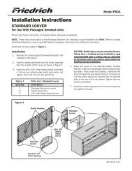
<strong>Installation</strong> InstructionsPOWER CORD ACCESSORY KITFor use with Packaged Terminal UnitsPlease read these instructions completely before attempting installation.NOTE: These instructions apply to the installation of <strong>Friedrich</strong> <strong>Power</strong> <strong>Cord</strong> <strong>Accessory</strong> <strong>Kit</strong>s only.How to connectIMPORTANT: Please read the following electrical safety data carefully.WARNINGFigure 1Removing the Front PanelElectrical Shock and/or UnitOperation and Damage HazardFailure to follow this warning could result inpersonal injury or death and/or unit damage.● Follow the National Electrical Code (NEC)or local codes and ordinances.● For personal safety, this unit MUST BEproperly grounded.● Protective devices (fuses or circuit breakers)acceptable for unit installations are specifiedon the nameplate of each unit.● Do not use an extension cord with this unit.● Aluminum wiring in the building may presentspecial problems - consult a qualifiedelectrician.● When unit is in STOP position, there isstill voltage to the electrical controls.● Disconnect power to unit before servicing by:1. Removing power cord (if it has one) fromwall receptacle.2. Removing branch circuit fuses or turningcircuit breakers off at panel.12FRP022Remove the front panel (see figure 1 above)Pull out at the bottom to release it from the tabs (1).Then lift up (2).NOTE: If the unit is mounted flush to the floor, theservice cord MUST be rerouted at the bottom of thefront cover on the side closest to the receptacle.A notch MUST be made in the front cover side wherethe cord exits the unit. It is the responsibility of theinstaller to create an exit notch.92016602
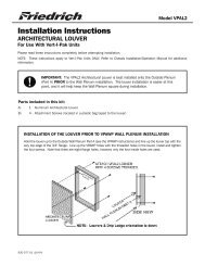
<strong>Installation</strong> InstructionsPOWER CORD ACCESSORY KITElectrical Rating TablesNOTE:Use Copper Conductors ONLY. Wire sizes are per NEC, check local codes for overseas applications.Table 1250V Receptacles and Fuse TypesAMPS 15 20* 30RECE<strong>PTAC</strong>LETIME-DELAY TYPE FUSE(or HACR circuit breaker)15 20 30HACR – Heating, <strong>Air</strong> Conditioning, Refrigeration* May be used for 15 Amp applications if fused for 15 AmpNOTE: 265 volt units are normally hard wired. For proper installationfollow the National Electrical Code (NEC) or local codes andordinances.WARNINGElectrical Shock HazardTurn off electrical power before serviceor installation.ALL electrical connections and wiringMUST be installed by a qualifiedelectrician and conform to the NationalCode and all local codes which havejurisdiction.Failure to do so can result in propertydamage, personal injury and/or death.FUSE/CIRCUITBREAKERGROUNDINGRECE<strong>PTAC</strong>LEUse ONLY type and size fuse or HACR circuitbreaker indicated on unit’s rating plate.Proper current protection to the unit is theresponsibility of the owner. NOTE: A timedelay fuse is provided with 265V units.Unit MUST be grounded from branch circuitthrough service cord to unit, or throughseparate ground wire provided on permanentlyconnected units. Be sure thatbranch circuit or general purpose outlet isgrounded. The field supplied outlet mustmatch plug on service cord and be withinreach of service cord. Refer to Table 1 forproper receptacle and fuse type. Do NOTalter the service cord or plug. Do NOT usean extension cord.The field supplied outlet must match plug onservice cord and be within reach of servicecord. Refer to Table 1 for proper receptacleand fuse type. Do NOT alter the servicecord or plug. Do NOT use an extensioncord.<strong>Power</strong> <strong>Cord</strong> Information (230/208V models only)All <strong>Friedrich</strong> 230/208V <strong>PTAC</strong> units are shipped from the factory with aLeakage Current Detection Interrupter (LCDI) equipped power cord. TheLCDI device meets the UL and NEC requirements for cord connected airconditioners effective August 2004.To test your power supply cord:1. Plug power supply cord into a grounded 3 prong outlet.2. Press RESET.3. Press TEST ( listen for click; Reset button trips and pops out).4. Press and release RESET (listen for click; Reset button latchesand remains in). The power supply cord is ready for operation.NOTE: The LCDI device is not intended to be used as a switch.Once plugged in the unit will operate normally without the need to resetthe LCDI device.If the LCDI device fails to trip when tested or if the power supply cord isdamaged it must be replaced with a new supply cord obtained from theproduct manufacturer, and must not be repaired.Figure 2Typical LCDI DevicesRESETW ARNINGTEST BEFORE EACH USE1. PRESS RESET BUTT ON2. PLUG LCDI INT O POWERRECEPT ACLE3. PRESS TEST BUTT ON,RESET BUTT ON SHOULDPOP UP4. PRESS TEST BUTT ON,FOR USEDO NOT USE IF ABOVE TESTF AILSWHEN GREEN LIGHT IS ONIT IS WORKING PROPERL YTESTTESTRESETW ARNINGTEST BEFORE EACH USE1. PRESS RESET BUTT ON2. PLUG LCDI INT O POWERRECEPT ACLE3. PRESS TEST BUTT ON,RESET BUTT ON SHOULDPOP UP4. PRESS TEST BUTT ON,FOR USEDO NOT USE IF ABOVE TESTF AILSWHEN GREEN LIGHT IS ONIT IS WORKING PROPERL Y15/20A LCDI Device 30A LCDI DeviceFRP01492016602
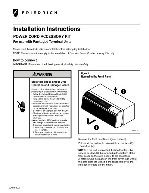
MedMed<strong>Installation</strong> InstructionsPOWER CORD ACCESSORY KIT1. Remove junction box.Remove junction box cover by removing threescrews from front. Remove junction box bytaking out top, rear and side screws.See Figure 3.1. Connect accessory power supply cord. SeeFigure 4.Units must be installed using the appropriatepower supply kit. See Table 2 below for powercord accessory options and ratings. Theseconnections must be followed.Figure 3Junction Box LocationFigure 4<strong>Power</strong> Connection<strong>Power</strong>Low FanFan Speed ModeHigh HeatCoolTemperatureUNITCONNECTOR<strong>Power</strong>Low FanFan Speed ModeHigh HeatCoolTemperatureJUNCTION BOXJUNCTION BOX COVERFRP017ACCESSORYPOWER SUPPLY CORDOR HARD WIREFRP018TABLE 2Model Heater kW <strong>Power</strong> <strong>Cord</strong> <strong>Kit</strong> Voltage Amperage ReceptaclePDE07K 0.0 PXPC23000 230/208 15 NEMA 6-15rPDE/PDH07K 2.0 PXPC23015 230/208 15 NEMA 6-15r3.0 STD 230/208 20 NEMA 6-20rPDE09K 0.0 PXPC23000 230/208 15 NEMA 6-15rPDE/PDH09K 2.0 PXPC23015 230/208 15 NEMA 6-15r3.0 STD 230/208 20 NEMA 6-20r5.0 PXPC23030 230/208 30 NEMA 6-30rPDE12K 0.0 PXPC23000 230/208 15 NEMA 6-15rPDE/PDH12K 2.0 PXPC23015 230/208 15 NEMA 6-15r3.0 STD 230/208 20 NEMA 6-20r5.0 PXPC23030 230/208 30 NEMA 6-30rPDE15K 0.0 PXPC23000 230/208 15 NEMA 6-15rPDE/PDH15K 2.0 PXPC23015 230/208 15 NEMA 6-15r3.0 PXPC23020 230/208 20 NEMA 6-20r5.0 STD 230/208 30 NEMA 6-30rPDE/PDH07R 2.0 PXPC26515 265 15 NEMA 6-15r3.0 STD 265 20 NEMA 6-20rPDE/PDH09R 2.0 PXPC26515 265 15 NEMA 6-15r3.0 STD 265 20 NEMA 6-20r5.0 PXPC26530 265 30 NEMA 6-30rPDE/PDH12R 2.0 PXPC26515 265 15 NEMA 6-15r3.0 STD 265 20 NEMA 6-20r5.0 PXPC26530 265 30 NEMA 6-30rPDE/PDH15R 2.0 PXPC26515 265 15 NEMA 6-15r3.0 PXPC26520 265 20 NEMA 6-20r5.0 STD 265 30 NEMA 6-30r92016602
<strong>Power</strong>MedHighCoolHeat<strong>Installation</strong> InstructionsPOWER CORD ACCESSORY KIT1. Reinstall junction box and cover.• Use wire clamp to attach power cord tobasepan. Secure with screws (included)See Figure 5.• Replace junction box and cover with screwsremoved from Step 2. Tighten securely.2. Replace front panel. See Figure 5.1. Place tabs over top rail (1). Push inward at bottomuntil panel snaps into place (2).2. Reinstall front panel. See Figure 6.Figure 5Wire ClampFigure 6Replacing Front PanelLow FanFan Speed ModeTemperature1WIRE CLAMPFRP0192FRP024To remove the front cover, pull the bottom end forwardand lift it up to clear the L bracket across the top ofthe chassis.1. Plug the cord into the appropriate receptacle.2. Restore power to the unit.Electrical Wiring for 265 Volt Models<strong>Power</strong> <strong>Cord</strong> <strong>Installation</strong>All 265V <strong>PTAC</strong>/PTHP units come with a factory installed non-LCDIpower cord for use in a subbase. If the unit is to be hard-wired refer tothe instructions in PXCJA kit.NOTE: It is recommended that the PXSB subbase assembly (orequivalent) the PXCJA conduit kit (or equivalent) be installedon all hardwire units. If installing a flush-floor mounted unit,make sure the chassis can be removed from the sleeve forservice and maintenance.92016602