SECTION 15420 WATER STORAGE TANKS AND ... - Shbc.com
SECTION 15420 WATER STORAGE TANKS AND ... - Shbc.com
SECTION 15420 WATER STORAGE TANKS AND ... - Shbc.com
You also want an ePaper? Increase the reach of your titles
YUMPU automatically turns print PDFs into web optimized ePapers that Google loves.
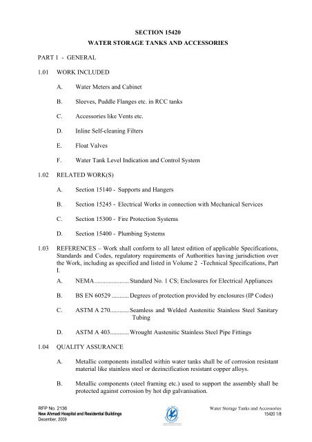
PART 1 - GENERAL1.01 WORK INCLUDED<strong>SECTION</strong> <strong>15420</strong><strong>WATER</strong> <strong>STORAGE</strong> <strong>TANKS</strong> <strong>AND</strong> ACCESSORIESA. Water Meters and CabinetB. Sleeves, Puddle Flanges etc. in RCC tanksC. Accessories like Vents etc.D. Inline Self-cleaning FiltersE. Float ValvesF. Water Tank Level Indication and Control System1.02 RELATED WORK(S)A. Section 15140 - Supports and HangersB. Section 15245 - Electrical Works in connection with Mechanical ServicesC. Section 15300 - Fire Protection SystemsD. Section 15400 - Plumbing Systems1.03 REFERENCES – Work shall conform to all latest edition of applicable Specifications,Standards and Codes, regulatory requirements of Authorities having jurisdiction overthe Work, including as specified and listed in Volume 2 -Technical Specifications, PartI.A. NEMA......................Standard No. 1 CS; Enclosures for Electrical AppliancesB. BS EN 60529 ...........Degrees of protection provided by enclosures (IP Codes)C. ASTM A 270............Seamless and Welded Austenitic Stainless Steel SanitaryTubingD. ASTM A 403............Wrought Austenitic Stainless Steel Pipe Fittings1.04 QUALITY ASSURANCEA. Metallic <strong>com</strong>ponents installed within water tanks shall be of corrosion resistantmaterial like stainless steel or dezincification resistant copper alloys.B. Metallic <strong>com</strong>ponents (steel framing etc.) used to support the assembly shall beprotected against corrosion by hot dip galvanisation.RFP No. 2136New Ahmadi Hospital and Residential BuildingsDecember, 2009Water Storage Tanks and Accessories<strong>15420</strong> 1/8
C. Section 15245 shall be referred to and <strong>com</strong>plied with in respect of all electricalworks.1.05 SUBMITTALS Submitted as specified and in accordance with Volume 2-TechnicalSpecifications, and as follows:A. Product data, samples and shop drawings.B. Co-ordinated positions of water-stops, construction joints etc. in water tank wallsshall be indicated in the shop drawings.C. Wiring diagram(s), details of <strong>com</strong>ponents and panel construction and mountingdetails shall be submitted in respect of water tank level control and indicationinstrumentation.1.06 DELIVERY, <strong>STORAGE</strong> <strong>AND</strong> H<strong>AND</strong>LINGA. Products shall be delivered to site, stored and protected under provisions of theTechnical Specification.B. Factory manufactured products shall be kept in shipping cartons until time ofinstallation.C. Factory calibrated items, which are dropped or subjected to shock otherwise,shall be stored in separate containers with appropriate labels till <strong>com</strong>pletion ofworks and a record of the same shall be maintained for inspection by theSuperintendent.PART 2 - PRODUCTS2.01 <strong>WATER</strong> METER, ACCESSORIES <strong>AND</strong> CABINETA. Water meter shall be as supplied by Ministry of Electricity ands Water (MEW)or their appointed agents. Meter shall have union / flanged ends to enable easydisassembly.B. Water meter cabinets shall be fabricated from minimum 2.0 mm (14 gauge)thick stainless steel sheets suitable for recessed / surface-mounted installation.Further,1. Joints shall be fully welded and ground smooth2. Stainless steel architrave shall be provided on recessed cabinets3. Doors shall have boxed edges, recessed stainless steel or aluminiumhandle and installed flush with the cabinet4. Hinges shall be solid, pin type machined from stainless steel rods andwelded to cabinet and door5. Foam rubber strips shall be adhered to doorframe to prevent rattling andto make the enclosure dust proofRFP No. 2136New Ahmadi Hospital and Residential BuildingsDecember, 2009Water Storage Tanks and Accessories<strong>15420</strong> 2/8
C. Following accessories shall be provided as part of the assembly:1. Gate valve at the inlet2. Check valve at the outlet3. Water tanker inlet connection with ball type isolating valve and malethreaded hose coupling2.02 IN-LINE SELF CLEANING FILTERSA. Type: Permanent media, back-washable type.B. Function: Dirt / rust removal to 20 microns filtration fineness.C. Construction: Stainless steel mesh filter with brass sump and body with unionconnections, rated for an inlet pressure of 400 psig.D. Accessories: Automatic back washing (daily) device with 24 v / 1 phase / 50 Hzpower supply unit. Furnish one set of filter elements as spare.Ref. : Honeywell Braukman F 76 S series and Z 11 S.2.03 FLOAT VALVESA. Delayed action float valves: Angle / Globe pattern, single seated, hydraulicallyoperated, pilot controlled, diaphragm type, normally closed valve of cast ironconstruction with flanged ends <strong>com</strong>plete with pilot assembly, type `K' coppercapillary lines, mounting plate, plastic float and operating rod, adjustable stopsetc. <strong>com</strong>plete.Ref. : Claval - Switzerland / Danfoss / Socla – FranceHoneywell - GermanyB. Modulating float valves: Angle / Globe pattern, single seated, hydraulicallyoperated, pilot controlled, diaphragm type, normally closed valve of cast ironconstruction with flanged ends <strong>com</strong>plete with pilot assembly, type `K' coppercapillary lines, mounting plate, plastic float and operating rod, adjustable stopsetc. <strong>com</strong>plete.Ref. : Claval - Switzerland / DANFOSS / SOCLA - FranceHoneywell - Germany2.04 <strong>WATER</strong> <strong>STORAGE</strong> TANK LADDERSA. Fabricated from austenitic stainless steel (type 316). Main rail shall be 32 mm(1 1/4 inch) DN and rungs shall be 25 mm (1 inch) DN in size. Joints shall bewelded and base plates of 100 x 100 x 10 mm size with drilled holes shall beprovided for attaching the ladders to walls. These base plates shall be bolted towall inserts and the ladder welded (at site) to them to attain good alignment.B. Safety cages made of 25 x 3 mm (1 x 1/8 inch) stainless steel flats shall beprovided for ladders exceeding 2.5 Ms (8 feet) in height. These shall beattached rigidly to ladders by bolting to specially prepared lugs on the ladderrail (omit on ladders inside tanks).RFP No. 2136New Ahmadi Hospital and Residential BuildingsDecember, 2009Water Storage Tanks and Accessories<strong>15420</strong> 3/8
C. Additional overhead rail made of 25 mm (1 inch) DN stainless steel tubes,bolted to ceiling soffit, shall be provided at the inside and outside of the tankaccess opening (in case of tanks with side access only).D. Stainless steel wall inserts (of pipe, puddle and stud plates at wall face) shall becast-in in the water storage tank walls for attaching ladders. Extra care shall betaken to attain proper alignment and water tightness. Appropriate detail shall beused to flash tanking membranes at ladder support bases.2.05 <strong>WATER</strong> <strong>STORAGE</strong> TANK ACCESS DOORS (On side walls)A. Doors and frames shall be fabricated from minimum 1.5 mm thick, stainlesssteel (type 316) sheets, boxed to form rigid sections. Corners shall be mitredand all joints welded full length to give a continuous smooth finish.B. Door frames shall be attached to concrete by nailing / screwing integral purposemade tabs, on the tank side. Joints of the frame with concrete shall be filled withsealant on the visible side.C. Door shall be constructed with a rectangular box frame with overlapping outeredge, hung with solid hinges welded to the frame. Concealed latch withrecessed handle shall be provided to keep the door in closed position.D. Air filter shall be supported on wire mesh backing (3mm wire @ 25 mm bothways) welded to the door framework. Single piece, viscous impingement type,synthetic air filter shall be provided to cover the opening in the doorframe withoverlap. The filter shall be held in position by another wire mesh facing, weldedto an L-section sheet framing attached to the door framework by metal screws.2.06 <strong>WATER</strong> <strong>STORAGE</strong> TANK VENTILATIONA. General1. Provision shall be made to allow for free entry and exit of air duringfilling or emptying of the tank2. Air passages of the vent shall be covered with copper / fine plastic wiremesh net, attached to the pipe with worm driven hose clamps, to preventthe entry of flies and pestsB. Goosenecks1. Material of construction shall be the same material as that of the piping,unless otherwise stated2. Joint of the gooseneck with the tank and / or overflow pipe shall beflanged. End of the gooseneck shall form a 135° arc from the horizontalplane, terminated square to the pipe axis3. Fasteners used shall be of corrosion resistant material like high tensilebrass or stainless steel2.07 PUDDLE FLANGESRFP No. 2136New Ahmadi Hospital and Residential BuildingsDecember, 2009Water Storage Tanks and Accessories<strong>15420</strong> 4/8
A. General1. Details on Drawings shall be referred to for minimum dimensions.External diameter of the puddle shall be approximately three (3) pipediameters (uPVC excluded)2. Bolting clearance of minimum 100 mm (4 inch) shall be provided fromthe rear face of the flange, where used, to the tank wall3. Integral flanges with studs / cap nuts at wall face and loose, split flangesshall be used to flash tanking membranes at the puddle flange4. Synthetic membrane flashing of 900mm (3 feet) diameter shall beprovided at puddle flanges installed in the bottom slab of water tanks.Flashing shall be integrated with the tanking, where usedB. Steel puddle flanges shall be fabricated from schedule 80 black steel pipe andwelding neck flanges. The assembly shall be hot dip galvanised afterfabrication.C. Stainless steel puddle flanges shall be fabricated from schedule 40 stainlesssteel pipe and welding neck flanges.D. Puddle flanges for plastic piping shall be fabricated from line size pipe andundrilled flange, solvent welded (uPVC) or hot air welded (HDPE) to the pipeas puddle. Manufacturer's proprietary products shall be acceptable in thisrespect.2.08 <strong>WATER</strong> <strong>STORAGE</strong> TANK LEVEL INDICATORS / CONTROLLERS (One Numberfor each Tank)A. Controller / indicator, Tank Guard 2001 - UK with required nos. of switchassemblies shall be provided in the following, in each <strong>com</strong>partment:1. Raw fresh water storage tanks at the sub-surface level2. Filtered sanitary / fire protection water storage tank at the sub-surfacelevel3. Filtered HVAC water storage tank at the sub-surface level4. Irrigation water storage tank(s) at the siteB. Indicator panel (<strong>com</strong>mon for all the tanks) in the plant room at sub-surfacelevel, containing the following:1. Mains isolator interlocked with the door and power on indicator (red)2. Remote indicator Tank Guard 2001 - UK for each set of tanks withselector switch for the <strong>com</strong>partments; with high / low level indicators3. Alarm buzzer with test and mute facility4. Externally mounted alarm bell5. Set of terminals / relays for inter connection with the filtration transferpump set, Building Management System etc.C. Alarm bell of weather proof construction, mounted on the external wall at 2500mm (8 feet) above finished floor level at the outside of the building close totanker fill point, wired to the indicator panel.RFP No. 2136New Ahmadi Hospital and Residential BuildingsDecember, 2009Water Storage Tanks and Accessories<strong>15420</strong> 5/8
D. Following shall be ac<strong>com</strong>plished:1. On site adjustment of set points2. Water level indication (dial shall be calibrated in cubic meters andimperial gallons)3. High / low water audio-visual alarms at the indicator panel4. High water audible alarm, at the tanker fill point, for:a. Raw fresh water storage tankb. Brackish water storage tank5. Cutting-out of:a. Sanitary fresh water booster pump set at the fire reserve levelb. HVAC makeup water booster pump set at low water levelc. Irrigation booster pump set at low water level6. Hook up with Building Management System for critical alarms2.09 CONTROL PANELS - GENERAL REQUIREMENTSA. Section 15245 shall be referred to and <strong>com</strong>plied with in respect of electricalsystem <strong>com</strong>ponents and control panels.2.10 CONDUITING <strong>AND</strong> WIRINGA. Section 15245 shall be referred to and <strong>com</strong>plied with in respect of wiring andcabling.B. Heavy duty galvanized iron conduits (surface mounted) and painted sheet steeltrunking shall be used for wiring.C. Stranded copper (1.5 mm 2 ), PVC insulated wires with crimped on, sheathedterminal lugs shall be used for all interconnecting wiring. Joints shall not beallowed in a single wire length. Terminals shall be numbered using slip-onferrules for quick identification.PART 3 - EXECUTION3.01 <strong>WATER</strong> METER CABINETSA. Wooden framing of correct size, extending to the plaster finish shall beprovided for recessed cabinets. Cabinets shall be secured in the wall by screws,at the wooden frame.B. Base supports fabricated from steel angles shall be provided for taking up theweight of cabinets installed in shaft walls.C. Openings in cabinets shall be made by using appropriate tools.D. Rubber grommets shall be provided at openings to prevent rattling and the entryof dust.RFP No. 2136New Ahmadi Hospital and Residential BuildingsDecember, 2009Water Storage Tanks and Accessories<strong>15420</strong> 6/8
E. Boxed sheet metal stiffeners or external supporting steel framing shall beprovided for installing hose reels and similar items.3.02 FLOAT VALVESA. Modulating type, pilot operated float valves shall be used in the fresh waterstorage tanks and brackish water storage tank for irrigation.B. Delayed action, pilot operated float valves shall be used on the make upconnections to the water wall balancing tanks.3.03 PUDDLE FLANGESA. Puddle flanges shall be used for all connections to water storage tanks, madebelow the overflow levelB. Puddle flanges shall be erected in the formwork perpendicular to the wall faceand rigidly to resist displacement during pouring of concrete.C. Verticality of the flange faces and alignment of boltholes with connectingequipment (valves etc.) shall be checked and ensured.D. Openings in formwork, around puddle flanges, shall be sealed so as to avoidleakage (and resultant honey <strong>com</strong>bing) and undesirable formation of concrete.E. Alignment of the puddle flanges shall be checked (and adjusted if necessary)immediately after pouring of the concrete.3.04 <strong>WATER</strong> <strong>STORAGE</strong> TANK VENTILATIONA. Goosenecks shall be used for ventilation of below grade RCC water storagetanks.B. Standpipes with hoods shall be used for ventilation of above grade waterstorage tanks of steel construction.3.05 LADDERS <strong>AND</strong> ACCESS DOORSA. Inserts shall be installed in the formwork for tank walls in a manner similar tothat of puddle flanges and good alignment shall be attained.B. Fasteners and cap nuts of corrosion resistant material shall be used for fixingthe ladder to the tank walls.3.06 LEVEL INDICATION <strong>AND</strong> CONTROL INSTRUMENTATION <strong>AND</strong> PANELSA. Section 15245 shall be referred to and <strong>com</strong>plied with in respect of electricalworks.RFP No. 2136New Ahmadi Hospital and Residential BuildingsDecember, 2009Water Storage Tanks and Accessories<strong>15420</strong> 7/8
B. Power supply to the system shall be obtained from the standby power supplynetwork, as far as possible. Conduiting and wiring to the source shall beincluded in this Section.C. Relays / volt free contacts in terminal blocks shall be provided forinterconnecting with other systems (like BMS).3.07 CLEANING, TESTING <strong>AND</strong> COMMISSIONING OF <strong>WATER</strong> <strong>STORAGE</strong> <strong>TANKS</strong>A. Inside of water storage tank(s) shall be thoroughly cleaned of all dirt, washeddown with water and drained prior to filling up with clean fresh water fortesting.B. Blank flanges / plugs shall be temporarily installed on the piping connections toRCC water storage tanks to enable the civil works contractor to test the watertightness of concrete tanks.C. Tank(s) shall be disinfected along with water supply piping and samples shallbe taken from within the tank(s) and tested for residual chlorine.D. On <strong>com</strong>pletion of tests, tanks shall be filled with clean fresh water from thestipulated source, water samples analysed and results submitted to theSuperintendent, prior to handing over.3.08 GUARANTEES <strong>AND</strong> WARRANTIESA. Company shall be furnished with guarantee and warranty certificates, dulyregistered with the manufacturer.END OF <strong>SECTION</strong>RFP No. 2136New Ahmadi Hospital and Residential BuildingsDecember, 2009Water Storage Tanks and Accessories<strong>15420</strong> 8/8


