The Quest for Speed at Sea - International Hydrofoil Society
The Quest for Speed at Sea - International Hydrofoil Society
The Quest for Speed at Sea - International Hydrofoil Society

You also want an ePaper? Increase the reach of your titles
YUMPU automatically turns print PDFs into web optimized ePapers that Google loves.
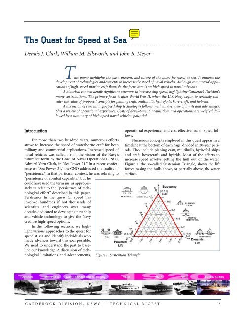
<strong>The</strong> <strong>Quest</strong> <strong>for</strong> <strong>Speed</strong> <strong>at</strong> <strong>Sea</strong>Dennis J. Clark, William M. Ellsworth, and John R. MeyerThis paper highlights the past, present, and future of the quest <strong>for</strong> speed <strong>at</strong> sea. It outlines thedevelopment of technologies and concepts to increase the speed of naval vehicles. Although commercial applic<strong>at</strong>ionsof high-speed marine craft flourish, the focus here is on high speed in naval missions.A historical context details significant <strong>at</strong>tempts to increase ship speed, highlighting Carderock Division’smany contributions. <strong>The</strong> primary focus is after World War II, when the U.S. Navy began to seriously considerthe value of proposed concepts <strong>for</strong> planing craft, multihulls, hydrofoils, hovercraft, and hybrids.A discussion of current high-speed ship technologies follows, with an overview of limits and advantages,plus a review of oper<strong>at</strong>ional experience. Costs of development, acquisition, and oper<strong>at</strong>ions are weighed, followedby a summary of high-speed naval vehicles’ potential.IntroductionFor more than two hundred years, numerous ef<strong>for</strong>tsstrove to increase the speed of w<strong>at</strong>erborne craft <strong>for</strong> bothmilitary and commercial applic<strong>at</strong>ions. Increased speed ofnaval vehicles was called <strong>for</strong> in the vision of the Navy’sfuture set <strong>for</strong>th by the Chief of Naval Oper<strong>at</strong>ions (CNO),Admiral Vern Clark, in “<strong>Sea</strong> Power 21.” In a recent conferenceon “<strong>Sea</strong> Power 21,” the CNO addressed the quality of“persistence.” In th<strong>at</strong> particular context, he was referring to“persistence of comb<strong>at</strong> capability,” but hecould have used the term just as appropri<strong>at</strong>elyto refer to the “persistence of technologicalef<strong>for</strong>t” described in this paper.Persistence in the quest <strong>for</strong> speed hasinvolved hundreds if not thousands ofscientists and engineers over manydecades dedic<strong>at</strong>ed to developing new shipand vehicle technology to give the Navycredible high-speed options.In the following sections, we highlightvarious approaches to the quest <strong>for</strong>speed <strong>at</strong> sea and identify individuals whomade advances toward this goal possible.We need to understand the past to baselineour knowledge. A discussion of technologicallimit<strong>at</strong>ions and advancements,Figure 1. Sustention Triangle.oper<strong>at</strong>ional experience, and cost effectiveness of speed follows.Numerous concepts employed in this quest appear in <strong>at</strong>imeline <strong>at</strong> the bottom of each page, divided in 20-year periods.<strong>The</strong>y include planing craft, multihulls, hydrofoil shipsand craft, hovercraft, and hybrids. Most of the ef<strong>for</strong>ts toincrease speed involve getting the hull out of the w<strong>at</strong>er.Figure 1, the so-called Sustension Triangle, shows the lift<strong>for</strong>ces raising the hulls above, or partially above, the w<strong>at</strong>ersurface.CARDEROCK DIVISION, NSWC — TECHNICAL DIGEST 3
DENNIS J. CLARK, WILLIAM M. ELLSWORTH, AND JOHN R. MEYERHow High-<strong>Speed</strong> Ships and Craft AdvancedHere we discuss significant craft and concepts th<strong>at</strong>advanced the quest <strong>for</strong> speed <strong>at</strong> sea over decades up to thepresent. We also identify key individuals who contributed tothese advances.Planing Craft Development<strong>The</strong> planing hull<strong>for</strong>m is perhaps the oldest, simplest,and most extensively employed member of the family ofmodern marine vehicles. As noted by Dr. Daniel Savitsky, 1modern planing hulls are designed to avoid the so-called“hump” problems, demonstr<strong>at</strong>e good behavior in a seaway,have substantial useful load fractions, and have a potential<strong>for</strong> growth to displacements up to 1,000 tons or more. <strong>The</strong>se<strong>at</strong>tributes establish planing hulls as effective members ofnaval units. In the period 1970 to 1983, 327 fast <strong>at</strong>tack unitsand 1,471 p<strong>at</strong>rol craft were constructed and exportedworldwide. <strong>The</strong>ir excellent cost-effectiveness r<strong>at</strong>io, simplicityof oper<strong>at</strong>ion, mini<strong>at</strong>urized electronics, and rel<strong>at</strong>ivelyheavy firepower <strong>at</strong>tract the <strong>at</strong>tention of many navies, particularlythose oper<strong>at</strong>ing in restricted w<strong>at</strong>ers. <strong>The</strong> modernplaning hull now has better seakeeping characteristics withlittle sacrifice in calm w<strong>at</strong>er per<strong>for</strong>mance.In the mid-1970s, the U.S. Navy undertook anadvanced planing hull research program aimed <strong>at</strong> improvingseakeeping while retaining as much speed as possibleand improving the lift-to-drag r<strong>at</strong>io of the hull through themid-speed range. This research led to the development ofthe high length-to-beam r<strong>at</strong>io, high beam loading, doublechine, and moder<strong>at</strong>e dead rise hull th<strong>at</strong> met all of therequirements of good seakeeping and good lifting efficiency.This prototype hull, in a development led by Jerry Gore<strong>at</strong> Carderock, was design<strong>at</strong>ed the Costal P<strong>at</strong>rol InterdictionCraft (CPIC-X). It became the U.S. benchmark design th<strong>at</strong>met the conflicting demands <strong>for</strong> the best compromise ofhigh speed and sea kindliness in one hull<strong>for</strong>m with minimumcost and complexity.Un<strong>for</strong>tun<strong>at</strong>ely, the aggressive and successful planinghull research program initi<strong>at</strong>ed in the early 1970s subsidedin the l<strong>at</strong>e 1970s, when the U.S. Navy decided to emphasizeacquisition of large comb<strong>at</strong>ants capable of transiting theworld’s oceans. With this philosophy, problems can arisewhen we need to engage in limited warfare in areas wherethe larger ships cannot oper<strong>at</strong>e close to shore, or in the innerharbors or rivers.Since 1990, Donald L. Blount and Associ<strong>at</strong>es, Inc.(DLBA) has specialized in the design, testing, and constructionof motor yachts, commercial ferries, and military vessels.Blount began his career in the Carderock Planing CraftBranch. In 1992, the motor yacht Destriero, designed byDBLA, captured the intern<strong>at</strong>ional speed record during anunrefueled passage from New York to England. This 67-mvessel, which averaged a speed of 53.1 knots in the crossing,is powered by two LM-1500 gas turbines, and is capable of aspeed of 65 knots.With the current new interest in the U.S. Navy’s LittoralComb<strong>at</strong> Ship (LCS) program, the advanced st<strong>at</strong>e of planingship technology represented by Destriero is of interest as acandid<strong>at</strong>e design <strong>for</strong> LCS. Don Blount is currently a memberof the Lockheed Martin LCS Team th<strong>at</strong> selected the <strong>Sea</strong>Blade ship concept th<strong>at</strong> builds on the hydrodynamic lineageof the Destriero.Multihull Ships<strong>The</strong> principal advantages of most multihulls are theirgre<strong>at</strong>er deck area <strong>for</strong> a given length, excellent transverse stability,and potential <strong>for</strong> reduced wave-making resistance inthe high-speed range <strong>for</strong> displacement ships. <strong>The</strong>se <strong>at</strong>tributesmake the c<strong>at</strong>amaran well suited to carrying low-densitycargo, <strong>for</strong> example as ferries. However, c<strong>at</strong>amaran hullsare prone to pitching, and the cross structure can be subjectto large wave impact <strong>for</strong>ces in rough seas.<strong>The</strong> concept of a multihull buoyantly supported vesselwas demonstr<strong>at</strong>ed <strong>at</strong> least a thousand years ago byPolynesian seafarers. <strong>The</strong> first known c<strong>at</strong>amaran in theWestern world was a sailbo<strong>at</strong> built in England in 1660.Beginning in the early 1800s, a sizeable number of steampaddle wheel-powered c<strong>at</strong>amaran ferrybo<strong>at</strong>s and river craftwere built there and in the U.S. 2Ef<strong>for</strong>ts to solve the seakeeping and ride com<strong>for</strong>t problemsled, in the 1960s, to the small-w<strong>at</strong>erplane-area twinhull(SWATH) ship configur<strong>at</strong>ion. Although the SWATHship is an important development with a number of desirablefe<strong>at</strong>ures, it is not currently considered a high-speedconcept and is not covered in this paper.C<strong>at</strong>amaransDuring the past decade, the c<strong>at</strong>amaran concept hasbeen employed mainly <strong>for</strong> commercial passenger transport.Since 1980, over 200 small high-speed c<strong>at</strong>amaran ferrieswere built, mainly in Australia, Norway, and Sweden.<strong>The</strong> seakeeping of the c<strong>at</strong>amaran is mixed. <strong>The</strong> hightransverse stability gives rise to pitch and roll <strong>at</strong> n<strong>at</strong>ural frequenciesth<strong>at</strong> are near each other. <strong>The</strong>se frequencies, in turn,yield motions th<strong>at</strong> feel more coupled than do those of themonohull. This effect has been described as a corkscrew4 CARDEROCK DIVISION, NSWC — TECHNICAL DIGEST
THE QUEST FOR SPEED AT SEAmotion, involving combined roll, pitch, and yaw. In thedesign process, knowledge of wave st<strong>at</strong>istics <strong>for</strong> the actualoper<strong>at</strong>ing area is vital. Model seakeeping testing in a facilityth<strong>at</strong> can gener<strong>at</strong>e a reliable represent<strong>at</strong>ion of wave environmentis also important <strong>for</strong> developing a successful design.Because of their effect on the resulting acceler<strong>at</strong>ions onboard a vehicle in a given seaway, the vessel’s n<strong>at</strong>ural periodsof pitch, heave, and roll are vital design parameters to consider.If any of the vessel’s n<strong>at</strong>ural periods are close to thewave encounter periods expected, the synchronism can leadto amplified motion responses.A design fe<strong>at</strong>ure th<strong>at</strong> demands thorough evalu<strong>at</strong>ion isthe shape and position above the still w<strong>at</strong>er level of theincreasingly commonly used cross-structure center hull. Inaddition to affecting vertical motions and acceler<strong>at</strong>ions, thisgeometric fe<strong>at</strong>ure, if designed carefully, can improve resistanceper<strong>for</strong>mance in waves.Semi-SWATHA semi-Small-W<strong>at</strong>erplane-Area Twin Hull (SWATH)ship is a combin<strong>at</strong>ion of a SWATH ship in the <strong>for</strong>ward halfand a conventional c<strong>at</strong>amaran in the stern half. <strong>The</strong> combin<strong>at</strong>ionresults in vehicles with nearly equal seakeeping to aregular SWATH ship, but with superior speed/poweringper<strong>for</strong>mance. <strong>The</strong> semi-SWATH ship concept also allowsthe integr<strong>at</strong>ion of w<strong>at</strong>erjet propulsion, by far the preferredchoice <strong>for</strong> high-speed ferries. <strong>The</strong> c<strong>at</strong>amaran-like aft sectionsare more suitable <strong>for</strong> machinery arrangement andespecially <strong>for</strong> integr<strong>at</strong>ing w<strong>at</strong>erjet propulsion. Like SWATHships, semi-SWATH ships offer a gre<strong>at</strong> deal of arrangeabledeck space and exhibit low resistance up to fairly highspeeds (40+ knots). 3<strong>The</strong> first and largest semi-SWATH ship in oper<strong>at</strong>ion isthe Stena HSS 1500 with a displacement of about 4,000tons. Other Semi-SWATH passenger vessels are Stena HSS900, and <strong>Sea</strong>jet 250. Although not quite as sensitive asSWATH ships, semi-SWATH ships are still somewh<strong>at</strong> sensitiveto overloading and trim. <strong>The</strong> small w<strong>at</strong>erplane of the<strong>for</strong>ward section makes them more susceptible, in particular,to changes in <strong>for</strong>ward trim.In 1966, Carderock Division began a multi-year programof c<strong>at</strong>amaran hydrodynamic and structural technologydevelopment to support the design of the ASR 21-class ofsubmarine rescue ships. By 1969, this development led tofurther in-house investig<strong>at</strong>ions of larger c<strong>at</strong>amarans as aircapableships or small aircraft carriers.Wave-Piercing C<strong>at</strong>amarans<strong>The</strong> increasing need <strong>for</strong> high-speed marine transport,coupled with the fact th<strong>at</strong> passengers often experience discom<strong>for</strong>tin open ocean or exposed routes on conventionalc<strong>at</strong>amarans, cre<strong>at</strong>ed a need th<strong>at</strong> the wave-piercer was developedto fill. Again, this hull<strong>for</strong>m has twin hulls, but they arelong and slender with minimal freeboard and little buoyancyin the bow section. This configur<strong>at</strong>ion allows the bows tocut or pierce the waves, reducing the tendency of the vehicleto contour, thus providing lower pitch motions and acceler<strong>at</strong>ions,while carrying similar deadweight. 3<strong>The</strong> wave-piercing c<strong>at</strong>amaran started in the early 1980s,with the development INCAT 28 m being the first to oper<strong>at</strong>eon a commercial route. Several companies have sincedeveloped their own approach to this type of design. One ofthe more famous wave-piercers is CONDOR II INCAT 78 m.CONDOR II reduces heave and pitch motions andacceler<strong>at</strong>ions while in bow seas. Due to the twin hulls andthe separ<strong>at</strong>ion between them, the vehicle has good inherentintact and damage stability. Large useable deck area resultsfrom separ<strong>at</strong>ion of hulls th<strong>at</strong> are still large enough aft toallow integr<strong>at</strong>ion of w<strong>at</strong>erjet propulsion and suitability <strong>for</strong>machinery arrangements.Due to the slenderness r<strong>at</strong>io of the hulls, these vehiclesare fairly efficient, and numerous oper<strong>at</strong>ing vehicles providegood st<strong>at</strong>istics regarding oper<strong>at</strong>ional characteristics.Construction is more difficult than conventional c<strong>at</strong>amaransdue to structural complexity of the <strong>for</strong>ward hulls. <strong>The</strong>wide beam of wave-piercer c<strong>at</strong>amarans is also an issuewhere ports are not designed to harbor such vehicles. Wavepiercerc<strong>at</strong>amarans may also experience l<strong>at</strong>eral jerkymotions in beam seas.TrimaransA trimaran is a multihulled vehicle with three hullssupported by hydrost<strong>at</strong>ic and hydrodynamic lift. <strong>The</strong>re aretwo approaches to making a trimaran. <strong>The</strong> first approach isto have a very slender center hull supported by two outboardhulls th<strong>at</strong> are smaller in both beam and length. <strong>The</strong>second approach is to have longer outboard hulls and ashorter center hull <strong>for</strong>ward. 3While trimarans have existed <strong>for</strong> centuries, only recentlyhas interest arisen in pursuing them as viable options <strong>for</strong>ferry and military applic<strong>at</strong>ions. <strong>The</strong> appearance in 1988 ofthe Ilan Voyager aroused interest in this concept. As of l<strong>at</strong>e,various defense departments investig<strong>at</strong>ed the use of a displacementtrimaran hull <strong>for</strong>m <strong>for</strong> frig<strong>at</strong>es and corvette-sizewarships, the l<strong>at</strong>est of which is the Royal Navy Tritondemonstr<strong>at</strong>ion trimaran. This ship has an overall length ofCARDEROCK DIVISION, NSWC — TECHNICAL DIGEST 5
DENNIS J. CLARK, WILLIAM M. ELLSWORTH, AND JOHN R. MEYER105 m, a beam overall of 20 m, and a displacement of about1,200 metric tons.<strong>The</strong> <strong>at</strong>tributes of trimaran hull<strong>for</strong>ms include goodhydrodynamic efficiency, allowing higher speed with lowerinstalled power, adequ<strong>at</strong>e intact and damage stability characteristics,large usable deck area, good seakeeping qualities,and good directional stability. However, they are structurallycomplex due to cross structures connecting the outerhulls, and the lack of design experience entails some risk.Also, the maneuvering characteristics of these hull<strong>for</strong>ms arerel<strong>at</strong>ively poor, unless the outer hulls are large enough toaccommod<strong>at</strong>e individual propulsion units.During the l<strong>at</strong>e 1980s, the U.S. Navy per<strong>for</strong>med a seriesof model tests <strong>at</strong> Carderock to investig<strong>at</strong>e a variant of theO’Neill Hull<strong>for</strong>m th<strong>at</strong> exploited the wave cancell<strong>at</strong>ionbetween the center body, the center surface-piercing strut,and the two outer hulls. Reference 4 discusses this hull <strong>for</strong>mand points out th<strong>at</strong> significant reductions in net total wavemakingresistance can be achieved <strong>at</strong> cruising speeds above24 knots. <strong>The</strong> resulting powering advantage of the WaveCancell<strong>at</strong>ion Multihull can be substantial. For example, <strong>for</strong>a 4,300-ton ship <strong>at</strong> a speed of 30 knots, the savings in effectivehorsepower (EHP) is between 22 and 28 percent comparedto the O’Neill Hull<strong>for</strong>m and SWATH VII configur<strong>at</strong>ions.Reference 4 also shows d<strong>at</strong>a comparing several monohullsand the Wave Cancell<strong>at</strong>ion Multihull concept.<strong>Hydrofoil</strong> Ships and CraftOne of the earliest ef<strong>for</strong>ts to lift the hull from the w<strong>at</strong>erwas by use of underw<strong>at</strong>er wing-like lifting surfaces calledhydrofoils. <strong>The</strong>se foils, like aircraft wings, follow theBernoulli principle. Air and w<strong>at</strong>er flowing over the curvedupper surface must move faster than th<strong>at</strong> flowing bene<strong>at</strong>h.This change in the flow p<strong>at</strong>tern results in low pressure onthe top surface and high pressure on the bottom surface. Ata given speed, the <strong>for</strong>ces gener<strong>at</strong>ed lift the hull out of thew<strong>at</strong>er.<strong>The</strong> Early Years<strong>The</strong> first hydrofoil craft was the product of an accidentin 1861. Thomas William Moy, an Englishman, studied theaerodynamics of wings by observing the vortices they cre<strong>at</strong>ed.He <strong>at</strong>tached wings to his craft and tested it in the SurreyCanal. To his surprise it rose from the w<strong>at</strong>er and, unintentionally,he discovered hydrofoils.In 1909, CAPT Holden C. Richardson USN (Ret), thena young Naval Constructor and an early seaplane designer,sought a solution to landing aircraft on the sea. Inspired byEnrico Forlanini in Italy, who proposed using hydrofoils aslanding gear <strong>for</strong> seaplanes, he fitted a set of submerged foilsto a dinghy. While under tow in the Philadelphia river, itlifted from the w<strong>at</strong>er and “flew” <strong>at</strong> a speed of about 6 knots.Richardson’s ef<strong>for</strong>ts in hydrofoil design continued <strong>at</strong> leastuntil 1911.A hydrofoil craft designed and built by the Italian aircraftdesigner Enrico Forlanini was the first successful suchcraft manned and motor driven. In 1906, he made test runsof a 1.6-ton craft on Lake Maggiore in Italy. <strong>The</strong> craft had a60-HP engine driving two counterrot<strong>at</strong>ing air propellers,and reached a top speed of 42.5 mph.Alexandra Graham Bell and his co-worker and friend F.W. (Casey) Baldwin became interested in hydrofoils as earlyas 1901. During a world tour, Bell and Baldwin rodeForlanini’s bo<strong>at</strong> on Lake Maggiore. On returning toCanada, Bell purchased a license to build and develop theForlanini ladder-foil system in North America. WithBaldwin as designer and engineer and Bell as advisor, theybuilt and tested a number of “hydrodomes.” Bell failed tointerest the U.S. Navy in the HD-3 and turned his <strong>at</strong>tentionto sailbo<strong>at</strong>s. With the U.S. entry into the European war,Bell’s hopes <strong>for</strong> hydrofoils revived when the U.S. NavyDepartment called <strong>for</strong> proposals to design and build subchasers.However, Bell’s offer to build two HD-4 hydrofoilcraft <strong>for</strong> th<strong>at</strong> purpose was rejected. <strong>The</strong> Navy sent him two50-HP Renault engines, and design work on an HD-4 continuedand incorpor<strong>at</strong>ed all th<strong>at</strong> had been learned from previoussuccesses and failures. With the Renault engines, thetop speed of the HD-4 was only 54 mph, but it per<strong>for</strong>medwell with good stability and took waves without difficulty.With Bell’s report of the success of these trials, in early 1919the Navy sent him two 350-HP Liberty engines. Using theseengines, on 9 September 1919, HD-4 set a new world’smarine speed record of 70.86 mph th<strong>at</strong> stood <strong>for</strong> the nextdecade. A year l<strong>at</strong>er, Bell got observers from the U.S. Navyand the British Admiralty to w<strong>at</strong>ch demonstr<strong>at</strong>ions of HD-4. Although all observers made enthusiastic reports, neithercountry saw fit to place an order. Some felt such a craft wastoo fragile <strong>for</strong> naval action <strong>at</strong> sea.From 1927 to 1936, Hanns Von Schertel, a youngGerman engineering gradu<strong>at</strong>e of the Technical University inBerlin-Charlottenburg, designed eight experimental hydrofoilcraft. After several disappointing experiences, hebecame convinced th<strong>at</strong> the only way to ensure stability ofsubmerged hydrofoils was by use of an autom<strong>at</strong>ic lift controland a submerged depth sensor. In the l<strong>at</strong>e 1930s, heteamed with Sachsenberg Shipyards in Germany to bid onthe German Navy’s request <strong>for</strong> proposals <strong>for</strong> a hydrofoilcraft to be used as a military personnel carrier over shortdistances. <strong>The</strong> Schertel/Sachsenberg entry, design<strong>at</strong>ed theVS-6, was selected, and several VS-6 models of about 15tons were built.6 CARDEROCK DIVISION, NSWC — TECHNICAL DIGEST
DENNIS J. CLARK, WILLIAM M. ELLSWORTH, AND JOHN R. MEYERIn January 1960, a group of experts from the UnitedSt<strong>at</strong>es, United Kingdom, and Canada concluded th<strong>at</strong> ahydrofoil ship promised significant improvement in ASWcapability. <strong>The</strong> hydrofoil concept was technically sound,and it complemented the hydrofoil development thenunderway in the U.S. Navy th<strong>at</strong> involved fully-submergedactively-controlled foil systems. At this point, the CanadianNaval Board recommended proceeding with design andconstruction of a 200-ton ship, design<strong>at</strong>ed the FHE-400(Fast <strong>Hydrofoil</strong> Escort).Hull construction of the FHE-400, designed byDeHavilland Aircraft, was begun <strong>at</strong> Marine Industries Ltd.,Sorel in 1964, and was completed in 1965. <strong>The</strong> hull waserected upside down to permit maximum use of downhandwelding of aluminum, and large sections of the shellwere welded as sub-assemblies. Un<strong>for</strong>tun<strong>at</strong>ely, in the finalstages of outfitting, in November 1966, a major fire brokeout in the engine room during tests of the auxiliary gas turbine.<strong>The</strong> center of the ship essentially had to be rebuilt. Itwas not until July 1968 th<strong>at</strong> the ship could be transferred toHalifax on the “slave dock” (a flo<strong>at</strong>ing barge) th<strong>at</strong> served asher maintenance base.From September 1968 to July 1971, the ship, christenedBras-D’Or, logged 552 hours hullborne and 96 hours foilbornein trials. Regrettably, significant rough-w<strong>at</strong>er d<strong>at</strong>awere small in number. However, hullborne seakeeping wasexceptionally good. Foilborne, under full load, she exceededher calm w<strong>at</strong>er design speed, achieving 63 knots in 3- to 4-ft waves. She took off and landed smoothly, and exhibitedgood stability and control <strong>at</strong> all speeds.In July 1969, with the ship docked to repair persistentfoil-system leaks, a large crack was discovered in the lowersurface of the center main foil. When the neoprene co<strong>at</strong>ingwas removed, an extensive network of cracks was found. Anew foil element was installed, but in July 1971 this foil alsodeveloped severe cracking. Clearly, the use of extremelyhigh yield-strength maraging steel was a major problem dueto stress-corrosion cracking.A decision was made in October 1971 to lay up theship. However, this decision was not due to the structuralproblem with the foils, but r<strong>at</strong>her was due to a change indefense policy issued in August 1971. This change in policyassigned priority not to ASW, but to the protection of “sovereignty”and the surveillance of Canadian territory andcoastlines. This decision would place the ASW hydrofoilship behind <strong>at</strong> least three major procurement programs <strong>for</strong>the Maritime Command. As a result, on 2 November 1971,the Minister of N<strong>at</strong>ional Defence announced in the Houseof Commons: “A decision has been made by the departmentto lay up the hydrofoil Bras D’Or <strong>for</strong> a five-year period.”Un<strong>for</strong>tun<strong>at</strong>ely, circumstances never occurred to restore theship to active service and the FHE-400 eventually became amuseum display sitting on its slave dock.<strong>The</strong> U.S. Navy Begins Explor<strong>at</strong>ory Research ProgramDuring the early 1950s, the U.S. Navy demonstr<strong>at</strong>edvarious experimental craft. 6 A common remark was “This isa lot of fun, but wh<strong>at</strong> would the Navy ever do with hydrofoils?”This viewpoint seemed to perme<strong>at</strong>e the entire earlyhistory of U.S. Navy hydrofoil development. <strong>The</strong> MarineCorps’ complaint th<strong>at</strong> the speed of approaching the beachhad not changed since William the Conqueror headed <strong>for</strong> abeach in 1066 sparked the Navy’s interest in hydrofoil landingcraft. As a result, a program began in 1954 to evalu<strong>at</strong>e ahydrofoil-supported landing craft design<strong>at</strong>ed the LCVP. Arequest <strong>for</strong> proposals (RFP) <strong>for</strong> an LCVP hydrofoil wasreleased by the Navy. An enthusiastic experimenter withhydrofoil craft, Christopher Hook, joined Bob Johnston,President of Miami Shipbuilding Corpor<strong>at</strong>ion, to respondto the RFP. To the Navy’s surprise, they won the competition.<strong>The</strong> LCVP was called Halob<strong>at</strong>es, named <strong>for</strong> a sea-goinginsect with <strong>for</strong>ward-extending feelers. One of the requirementsof the design was th<strong>at</strong> the craft be capable of flying inshallowing w<strong>at</strong>er. As it approached the beach <strong>for</strong> a landing,the foils were retractable with diminishing foil depth, witha continuous transition from foilborne to hullborne as thew<strong>at</strong>er shoaled. During flight test, Halob<strong>at</strong>es reached speedsup to 34 knots in five-foot waves. Its per<strong>for</strong>mance wasdemonstr<strong>at</strong>ed over a range of weights from 23,290 to 31,165pounds. <strong>The</strong> Navy disagreed with the use of the large feelerarms and considered them quite impractical. Fortun<strong>at</strong>ely, aMiami Shipbuilding electronic autopilot was ready to go. Astep resistance, on the leading edge of the <strong>for</strong>ward struts,provided a height signal. <strong>The</strong> Navy also became interestedin the use of lightweight gas turbine engines. As a result,when an electronic autopilot was installed in Halob<strong>at</strong>es, anAVCO T-53 gas turbine was also installed.From 1951 to 1954, funds were budgeted to build a3,500-ton hydrofoil cargo carrier with a destroyer-type hull.<strong>The</strong> Office of Naval Research (ONR) was given Navy programmanagement responsibility supported by the Bureauof Ships, Bureau of Aeronautics, and NSWC Carderock. <strong>The</strong>basic research was undertaken by the <strong>Hydrofoil</strong>Corpor<strong>at</strong>ion of America, a non-profit organiz<strong>at</strong>ion <strong>for</strong>medby Dr. Vannevar Bush, President of the Carnegie Institutionand scientific advisor to the President of the United St<strong>at</strong>es.LCDR P<strong>at</strong>rick Leehy was design<strong>at</strong>ed Project Officer inONR. CDR Robert Johnston l<strong>at</strong>er replaced him. In 1954, itwas concluded th<strong>at</strong> the development of a propulsion system<strong>for</strong> a 3,500-ton hydrofoil might tax the total capability ofU.S. industry. On this note, the project was termin<strong>at</strong>ed.8 CARDEROCK DIVISION, NSWC — TECHNICAL DIGEST
THE QUEST FOR SPEED AT SEAA small 5-ton, modified Chris-Craft perhaps did themost to interest the U.S. Navy in the future potential ofhydrofoil craft. <strong>The</strong> craft had its genesis in the 1950s <strong>at</strong> thenaval architecture firm of Gibbs & Cox. <strong>The</strong>y assembled ahydrofoil team headed by Tom Buerman th<strong>at</strong> included Dr.John Breslin, Dr. S.F. Hoerner, L.E. Sutton, and RichardBrowne. In 1954, Sutton and Browne were assigned tosupervise construction of an autopilot-stabilized test craftth<strong>at</strong> was to become <strong>Sea</strong> Legs. It had a 28.5-ft hull with a 9.0-ft beam, full-load weight of 10,550 lbs. <strong>The</strong> foils were aluminumwith a German section and were arranged in acanard configur<strong>at</strong>ion. For the autopilot, Richard Brownestarted with the basic technology developed by the DraperLabor<strong>at</strong>ory of MIT and assembled a practical workingautopilot with 160 vacuum tubes. For the height signal, itutilized a sonic height sensor. <strong>The</strong> autopilot and height sensorwere significant technical advances.<strong>Sea</strong> Legs’ first flight in 1957 was impressive. 7 <strong>The</strong>autopilot stabilized the craft in rough seas and it achievedspeeds up to 27 knots. After Navy personnel witnessed thetrials in the New York area during l<strong>at</strong>e 1957 and early 1958,<strong>Sea</strong> Legs got underway to Washington, DC. During the transitin the open ocean, accompanied by the U.S. Navy’s PT-812, <strong>Sea</strong> Legs averaged 23 knots in 4 to 5-ft waves. <strong>The</strong>hydrofoil craft demonstr<strong>at</strong>ed seakeeping and per<strong>for</strong>manceabsolutely impossible <strong>for</strong> conventional bo<strong>at</strong>s of the same, oreven larger size. Those aboard reported a dry, com<strong>for</strong>tableride, while conditions on the PT-812 were quite differentindeed. Three Navy Commanders, William Nicholson,Randolph King, and Kenneth Wilson headed this adventure.When <strong>Sea</strong> Legs arrived in Washington, a number of interestedmilitary and government personnel were embarked <strong>for</strong>further demonstr<strong>at</strong>ions. <strong>The</strong>y included the CNO, AdmiralArleigh Burke.In 1962 and 1963, <strong>Sea</strong> Legs underwent more detailedevalu<strong>at</strong>ion by the Carderock Division. It was extensivelyinstrumented and provided <strong>at</strong>-sea d<strong>at</strong>a <strong>for</strong> future designs.This small bo<strong>at</strong> was the single most important <strong>for</strong>erunner ofthe U.S. Navy’s decision to get serious about the use ofhydrofoil ships and craft in the future Navy fleet. In recognitionof its importance, <strong>Sea</strong> Legs is presently on exhibit inthe Mariner Museum in Newport News, VA.<strong>The</strong> U.S. Navy Gets SeriousWith the growing momentum gener<strong>at</strong>ed by theexpanding technology base, and the demonstr<strong>at</strong>ed <strong>at</strong>tributesof hydrofoils <strong>for</strong> naval missions, the Bureau of ShipsPreliminary Design Branch began a design study, in l<strong>at</strong>e1957, of hydrofoils <strong>for</strong> ASW. This study was strongly influencedby Canada’s development of the hydrofoil ASW shipFHE-400. In a letter d<strong>at</strong>ed 24 January 1958, OPNAVrequested BuShips to study a hydrofoil <strong>for</strong> harbor defenseand coastal p<strong>at</strong>rol. Design<strong>at</strong>ed the PC(H), when comparedto the sub chasers PC(S) and SC, it appeared capable of per<strong>for</strong>mingthe mission of these p<strong>at</strong>rol craft in a superior manner.As a result, the PC(H) was substituted <strong>for</strong> the PC(S) andSC in the FY60 shipbuilding program. With the blessing ofOPNAV, PC(H) design work continued until March 1959when the preliminary design was completed. Based on theexperience with <strong>Sea</strong> Legs, the selected design was a fullysubmerged,autopilot-controlled foil system in a canardconfigur<strong>at</strong>ion. It was thus th<strong>at</strong> the many years of hydrofoilresearch finally bore fruit with the design and acquisition ofwh<strong>at</strong> was expected to be the U.S. Navy’s first oper<strong>at</strong>ionalhydrofoil ship.<strong>The</strong> contract plans and specific<strong>at</strong>ions <strong>for</strong> PCH wereturned over to BuShips Code-526, the Mine, Service, andP<strong>at</strong>rol Craft Branch, otherwise known as the Type Desk.<strong>The</strong> contract <strong>for</strong> detailed design and construction was to bebid on a competitive, fixed-price basis. In June 1960, <strong>The</strong>Boeing Company in Se<strong>at</strong>tle, WA was awarded a contract <strong>for</strong>a fixed price of $2.08 million to do detailed design and construction.Boeing’s research and entry into hydrofoil programsbegan in 1958 with in-house funding. A MarineGroup was <strong>for</strong>med in 1959 as part of the AerospaceDivision. L<strong>at</strong>er it became Boeing Marine Systems. Hull loftingbegan in the Fall of 1960 <strong>at</strong> Martinac Shipyard inTacoma, WA. <strong>The</strong> ship, design<strong>at</strong>ed the PCH-1, was launchedin conventional fashion the evening of 17 August 1962, andchristened High Point, after High Point, NC.In retrospect, it seems no surprise th<strong>at</strong> the builder’s trials,post-delivery tribul<strong>at</strong>ions, special per<strong>for</strong>mance trials,and final acceptance trials, clearly demonstr<strong>at</strong>ed th<strong>at</strong> theship was not ready, and possibly might never be ready, <strong>for</strong>delivery to the fleet. This fact was finally recognized, andOPNAV made the decision to transfer the ship to NSWCCarderock to continue development of the technology base<strong>for</strong> design of naval hydrofoil craft and ships. <strong>The</strong> followingtwenty years of the PCH-1 trials, modific<strong>at</strong>ions, and explor<strong>at</strong>ionof mission applic<strong>at</strong>ions appear in detail inReference 8.In 1961, BuShips initi<strong>at</strong>ed the <strong>Hydrofoil</strong> Acceler<strong>at</strong>edResearch Program (HARPY) directed toward bigger, better,and faster hydrofoil ships. James Schuler, <strong>Hydrofoil</strong>Program Manager, initially directed the program with assistancefrom Owen Oakley and Ralph Lacey in Code 420. <strong>The</strong>need <strong>for</strong> a high-speed test craft to investig<strong>at</strong>e sub-cavit<strong>at</strong>ing,ventil<strong>at</strong>ed, and super-cavit<strong>at</strong>ing foil systems was evident. InJune 1961, BuShips awarded a contract to Boeing to designand construct a high-speed test craft th<strong>at</strong> could be highlyinstrumented and propelled <strong>at</strong> speeds up to 100 knots. ThisCARDEROCK DIVISION, NSWC — TECHNICAL DIGEST 9
DENNIS J. CLARK, WILLIAM M. ELLSWORTH, AND JOHN R. MEYERcraft, named FRESH-1 (Foil Research <strong>Hydrofoil</strong>), waslaunched on 8 February 1963. Powered by an aircraft turbineengine on 3 May 1963, it <strong>at</strong>tained a speed of 80 knots.FRESH-1 characteristics and test oper<strong>at</strong>ions appear inReference 9. During one of its trial runs, in a turn, the craftbecame unstable due to foil ventil<strong>at</strong>ion and capsized.Fortun<strong>at</strong>ely, there were no casualties. As a result of theNavy’s decision to delay, CNO Admiral Zumwalt’s quest <strong>for</strong>a 100-knot Navy, FRESH-1 was laid up.On 10 November 1966, NSWC Carderock establishedthe <strong>Hydrofoil</strong> Special Trials Unit (HYSTU) as a tenantactivity of the Puget Sound Naval Shipyard (PSNS). It wasstaffed by LCDR Karl Duff, USN as the Officer in Charge,and a number of technical and administr<strong>at</strong>ive personnel.<strong>The</strong> Officer in Charge of HYSTU, and the assigned hydrofoilships were administr<strong>at</strong>ively assigned to CO&DCarderock with local control by COM 13 in Se<strong>at</strong>tle. Civilianpersonnel were responsible to the Technical Manager of the<strong>Hydrofoil</strong> Development Program Office <strong>at</strong> NSWCCarderock.During the period when PCH-1 was under construction,the Navy contracted with the Grumman Corpor<strong>at</strong>ion<strong>for</strong> the design of the 320-ton hydrofoil ship AGEH-1. 10Lockheed Shipbuilding in Se<strong>at</strong>tle, WA constructed it. <strong>The</strong>ship, christened Plainview, after Plainview, TX and NY, wasdelivered to the Navy in 1969. At th<strong>at</strong> time it was the largesthydrofoil ship in the world. It was originally planned as anASW ship and was designed to achieve speeds of 90 to 100knots. However, due to experiences with other hydrofoils,the decision was made to install only two LM-1500 gas turbineswith space available <strong>for</strong> adding two more, thus limitingthe speed to a nominal 50-60 knots. Also, r<strong>at</strong>her thandeploying the ship to the fleet, it was assigned to theCarderock <strong>Hydrofoil</strong> Special Trials Unit <strong>for</strong> additional R&Dtrials.<strong>The</strong> first U.S. Navy oper<strong>at</strong>ional hydrofoils delivered tothe fleet were the p<strong>at</strong>rol gunbo<strong>at</strong> hydrofoils (PGHs). TwoPGHs were built, one by Grumman, Flagstaff (PGH-1), andone by Boeing, Tucumcari (PGH-2). Although designed andbuilt to the same per<strong>for</strong>mance specific<strong>at</strong>ions, their configur<strong>at</strong>ionswere substantially different. PGH-1 was propellerdriven and had a conventional foil distribution. PGH-2 wasw<strong>at</strong>erjet propelled and had a canard foil system. <strong>The</strong>y weredelivered to the Navy in 1968 and both saw service inVietnam, making them the first U.S. Navy hydrofoils incomb<strong>at</strong>. <strong>The</strong> oper<strong>at</strong>ional experience gained with thesehydrofoils, particularly the Tucumcari, provided the confidencenecessary to proceed with the P<strong>at</strong>rol <strong>Hydrofoil</strong> Missile(PHM) ship program.NATO Navies Join <strong>Hydrofoil</strong> ProgramIn 1972, three NATO navies <strong>for</strong>mally agreed to proceedwith the joint development of a high-speed hydrofoil comb<strong>at</strong>ant.A Memorandum of Understanding (MOU) wassigned by the United St<strong>at</strong>es, Federal Republic of Germany,and Italy. A letter contract was awarded to the BoeingCompany <strong>for</strong> a feasibility study, and the design and constructionof two P<strong>at</strong>rol Comb<strong>at</strong>ant Missile (<strong>Hydrofoil</strong>)Ships. 11 Although the initial contract called <strong>for</strong> two leadships, program cost growth in August 1974 <strong>for</strong>ced suspensionof the work on the second ship. PHM-2 was l<strong>at</strong>er incorpor<strong>at</strong>edinto the production program. Nearly six yearselapsed from the signing of the letter contract <strong>for</strong> the designand construction of the lead ship, PHM-1, in November1971. She was commissioned as USS Pegasus in July 1977. Itwas not until 1981 and 1982 th<strong>at</strong> the five additional PHMsjoined the PHM-1 to <strong>for</strong>m the desired squadron of six ships.<strong>The</strong> PHM Squadron was based in Key West, FL and assignedto support the U.S. Coast Guard in intercepting drug smugglerswho were using high speed “Cigarette” bo<strong>at</strong>s. 11 <strong>The</strong>iroper<strong>at</strong>ional experience is described in a following section.To the dismay of the advoc<strong>at</strong>es of Naval hydrofoil ships, on30 July 1993 <strong>at</strong> the Naval Amphibious Base, Little Creek, VA,the Navy decommissioned the entire Class of PHMs in oneday, the first such act in naval history. <strong>The</strong> ships were inmint condition, had fulfilled all expect<strong>at</strong>ions <strong>for</strong> their per<strong>for</strong>mance,and had another 15 years of useful life. <strong>The</strong> CoastGuard indic<strong>at</strong>ed they would be glad to take over thesquadron, but the Navy had to provide the oper<strong>at</strong>ing funds.<strong>The</strong> Navy refused. In time, except <strong>for</strong> one of the ships, allothers were sold <strong>for</strong> scrap. Since th<strong>at</strong> time, the Navy has notoper<strong>at</strong>ed hydrofoil ships.U.S. Navy <strong>Hydrofoil</strong> Ef<strong>for</strong>t Focused On Design ConceptsSince the mid-1980s, advancement of hydrofoil conceptsin the U.S. Navy has been restricted essentially to“paper” studies, although subsystem technologies have continuedto advance. Even though currently there are nohydrofoil ships in the U.S. Naval fleet, interest continues indeveloping the technology and improving the subsystems<strong>for</strong> these ships. <strong>The</strong> hydrofoil community, of whichCarderock is a major contributor, continues to carry outconceptual studies and feasibility designs of rel<strong>at</strong>ively largehydrofoil ships to suit a variety of mission applic<strong>at</strong>ions. Inthis respect, a fundamental limit<strong>at</strong>ion impacts the growthpotential of hydrofoil ships. It is the “square-cube” law th<strong>at</strong>st<strong>at</strong>es the lift developed by foils is proportional to their plan<strong>for</strong>m area (the square of a linear dimension), whereas theweight to be supported is proportional to the volume (thecube of a linear dimension). Thus, as the size of the ship10 CARDEROCK DIVISION, NSWC — TECHNICAL DIGEST
DENNIS J. CLARK, WILLIAM M. ELLSWORTH, AND JOHN R. MEYERtotype LACV-30s. <strong>The</strong>y were an adapt<strong>at</strong>ion of Bell AerospaceTextron’s commercial ACV Voyageur with major improvements.Two Pr<strong>at</strong>t & Whitney ST6T-76 twin-pack gas turbineengines, r<strong>at</strong>ed <strong>at</strong> 1,800 SHP, powered them. <strong>The</strong>y each drovethree-bladed, 9-foot diameter, Hamilton Standard variablepitchpropellers. Based on the experience with these two prototypes,the Army purchased a total of 26 LACV-30s.Although the LACV-30 fulfilled a major need in theArmy Logistics Over <strong>The</strong> Shore (LOTS) requirement, somerequirements remained unmet. <strong>The</strong> transport<strong>at</strong>ion ofheavy, outsize cargo quickly exceeded the LACV-30 capability.<strong>The</strong> Army approved a Letter of Agreement <strong>for</strong> a LAMP-H on 24 May 1982. <strong>The</strong> LAMP-H was required to transportheavy equipment, LOTS support equipment, the M-1 tank,tracked and wheeled vehicles, 20- and 40-ft containers, andgeneral cargo. In response to these requirements, the Armyevalu<strong>at</strong>ed four candid<strong>at</strong>e concepts: the Marine Corps LCAC,a modified U.K. SR.N4 ferry, an air cushion barge, and amodified LACV-30.<strong>The</strong> Army oper<strong>at</strong>ed the LACV-30s up until the mid1990s. Most of these were ultim<strong>at</strong>ely turned over to a N<strong>at</strong>iveAlaskan corpor<strong>at</strong>ion th<strong>at</strong> continues to lease them to meetrequirements in Alaska.Navy and Marine Corps Begin LCAC Program<strong>The</strong> Landing Craft Air Cushion (LCAC) is a dram<strong>at</strong>icinnov<strong>at</strong>ion in modern amphibious warfare technology. Itprovides the capability to launch an assault from over thehorizon, thereby decreasing the risk to ships and personneland cre<strong>at</strong>ing uncertainty <strong>for</strong> the enemy as to where theassault might occur.In the 1965-1970 period, the U.S. Navy and MarineCorps undertook studies of the applic<strong>at</strong>ion of the air cushionprincipal to improve amphibious landing craft. Two craftwere designed and constructed: the JEFF (A) by AerojetGeneral Corpor<strong>at</strong>ion, and the JEFF (B) by Bell Aerospace. InOctober 1977, Carderock established the Assault LandingCraft Experimental Trials Unit in Panama City, FL <strong>for</strong> thepurpose of testing these two air cushion prototypes. <strong>The</strong> Jeff(B) was launched on 17 December 1977 and made its firsttrial run reaching a speed of 42 knots. <strong>The</strong> Jeff (A) made itsfirst run <strong>at</strong> Panama City, FL on 17 October 1978.Based on the results of these trials, Bell AerospaceTextron was awarded a contract in 1981 to begin the productionof the Landing Craft Air Cushion (LCAC). <strong>The</strong>secraft are powered by four Avco-Lycoming TF40B gas turbines,each r<strong>at</strong>ed <strong>at</strong> 3,955 SHP (two <strong>for</strong> propulsion and two<strong>for</strong> lift). <strong>The</strong> craft are capable of carrying a 60-ton payloadand 75 tons in overload. <strong>The</strong>y can carry a main b<strong>at</strong>tle tank,with a range of 200 nautical miles <strong>at</strong> 40 knots with payloadin sea st<strong>at</strong>e 2, and 300 nautical miles <strong>at</strong> 35 knots withoutpayload. Four LCACs can be carried in the LSD 41 class and3 in the LSD 36 class.On 29 June 1987, the LCAC was approved <strong>for</strong> full production.Textron was awarded a contract to deliver 48 craftthrough FY 1989. Lockheed Shipbuilding was also selectedas a second source. As of 1995, 82 LCACs were delivered.<strong>The</strong> largest deployment of LCACs took place in January1981 with 4 detachments of 11 craft reported <strong>for</strong> duty in thePersian Gulf in support of Oper<strong>at</strong>ion Desert Storm.As of this d<strong>at</strong>e, 92 LCACs have been delivered, andTextron Marine and Land Systems is currently under contractto per<strong>for</strong>m a Service Life Extension Program (SLEP) toextend the craft’s life beyond 20 years.Why Surface Effects Ships (SES)?Although the Surface Effect Ship (SES) has a number ofunique advantages, the principal motiv<strong>at</strong>ion behind theconcept is th<strong>at</strong> the air cushion, which supports the majorityof the weight of the craft, significantly reduces the resistanceto <strong>for</strong>ward motion <strong>at</strong> high speed. It also helps to mitig<strong>at</strong>e theeffect on craft motions and acceler<strong>at</strong>ions when oper<strong>at</strong>ing inrough seas. Although power is required to cre<strong>at</strong>e and sustainthe air cushion, the reduction in resistance is so large <strong>at</strong> highspeed th<strong>at</strong> the sum of lift and propulsion power is significantlyless than th<strong>at</strong> <strong>for</strong> the equivalent monohull.SES Development BeginsIn 1959, Ted T<strong>at</strong>tersall in the U.K. initi<strong>at</strong>ed developmentof the first solid sidewall hovercraft, l<strong>at</strong>er called theSES. At about the same time in the U.S., a small team led byAllen Ford, <strong>at</strong> the Naval Air Warfare Research Departmentof the Naval Air Development Center (NADC), invented asimilar concept called the “Captured Air Bubble.” This hovercrafthad rigid sidewalls th<strong>at</strong> penetr<strong>at</strong>ed the w<strong>at</strong>er surfaceand contained an air cushion between them sealed <strong>for</strong>e andaft with bow and stern seals. Ford claimed th<strong>at</strong>, despite theloss of amphibious capability, the design resulted in a muchhigher lift-to-drag r<strong>at</strong>io due to the reduction of air leakage.<strong>The</strong> T<strong>at</strong>tersall team, with the backing of William Denny& Bros., licensees of Hovercraft Development Limited, builtthe first U.K. 70-foot manned model with a cushion Lengthto-Beam(L/B) r<strong>at</strong>io of 7:1. It had a weight of 5 tons and waspowered by two 35-HP Mercury outboard motors.Introduced on 22 June 1961 as the D.1, the craft made 18knots and lifted the cross-structure above the surface of thew<strong>at</strong>er. It was successful enough to lead to the building of the70-passenger, 20-knot GRP SES D.2 th<strong>at</strong> went into experimentalpassenger service in 1963.12 CARDEROCK DIVISION, NSWC — TECHNICAL DIGEST
THE QUEST FOR SPEED AT SEAIn the U.S., Allen Ford launched the XR-1 in May 1963.It was 50 feet long, weighed 10 tons, and was propelled by aJ-79 jet engine. <strong>The</strong> craft’s Length-to-Beam (L/B) was 3.5and, with a more powerful J-85 engine, it achieved a speedof 60 knots. In 1965, Ford joined Harvey Chaplin <strong>at</strong>Carderock. His original design went through eight majormodific<strong>at</strong>ions leading up to the XR1-E, some 22 years l<strong>at</strong>er.Four were built as commercial ferries capable of carrying 70passengers <strong>at</strong> a speed of 27 knots, subsequently modified togive a maximum speed of 34 knots.Although the top speed of early oper<strong>at</strong>ional SESs wasless than 40 knots, the historical thrust was to develop an80- to 100-knot capability. In 1969, design and constructioncontracts were awarded to Aerojet General <strong>for</strong> the SES 100-A and to Bell Aerospace <strong>for</strong> the SES 100-B test craft. Both ofthese 100-ton craft were extensively oper<strong>at</strong>ed, and valid<strong>at</strong>edtheir architectural and engineering technologies and subsequentmodific<strong>at</strong>ions. <strong>The</strong> SES 100-B established a sustainedspeed record of 91.9 knots in a slight chop on LakePonchartrain, and also oper<strong>at</strong>ed <strong>at</strong> 35 knots in 6- to 8-footwaves. In 1978, the SES 100-A served as a scale model <strong>for</strong> thedesign and construction of the Navy’s 3,000-ton, 80-knotprototype, called the 3K SES. Un<strong>for</strong>tun<strong>at</strong>ely, the 3K SESprogram was termin<strong>at</strong>ed in December 1979, just threeweeks be<strong>for</strong>e beginning hull construction and after anexpenditure of over $400 million. This termin<strong>at</strong>ion, basedmainly on the lack of a mission <strong>for</strong> a large prototype, frustr<strong>at</strong>edthe thrust <strong>for</strong> a 100-knot Navy.<strong>The</strong> SES-200: Exploring New GeometriesMilitary applic<strong>at</strong>ions of SESs required examin<strong>at</strong>ion ofthe early geometry. Low L/B r<strong>at</strong>ios and thin side hulls characterizedmost of the early SESs. <strong>The</strong>y were designed tooper<strong>at</strong>e almost exclusively on cushion <strong>at</strong> high post-primaryhump drag speeds. This design proved to be efficient <strong>for</strong>ferry oper<strong>at</strong>ion but not <strong>for</strong> military applic<strong>at</strong>ions.In the l<strong>at</strong>e 1970s, Bell Aerospace joined with HalterMarine to build the BH-110 SES as a shuttle to serve oil rigsin the Gulf of Mexico. Together they built four of these craft.Un<strong>for</strong>tun<strong>at</strong>ely, the 1970s mor<strong>at</strong>orium on oil drilling in theGulf resulted in a loss of this market. <strong>The</strong>y tried to find newcustomers about the time the 3K-SES program was termin<strong>at</strong>ed.<strong>The</strong> focus of Navy SES interest turned to lower technologyand somewh<strong>at</strong> lower speed. Bell Halter developedCoast Guard interest in a small, fast cutter to deal with drugsmuggling “Cigarette” bo<strong>at</strong>s in the Florida Keys. A cooper<strong>at</strong>ivetrials program was conducted by the Navy and theCoast Guard using a BH-110 <strong>for</strong> about a year. This programresulted in sufficient interest <strong>for</strong> the Navy to acquire oneBH-110, and <strong>for</strong> the Coast Guard to acquire the other three.In the early 1980s, in order to advance the technologybase of high L/B SES craft, the Navy awarded Bell a contractto stretch their BH-110 with a 50-foot extension of the hull.This craft was design<strong>at</strong>ed the SES-200, which was about200-tons displacement. Bell also installed a prototype ridecontrol system. <strong>The</strong> result of the stretch to a higher L/B r<strong>at</strong>iogave better seakeeping and a lower oper<strong>at</strong>ing cost below theprimary hump. Special note is made of this craft because ofits extensive employment in advancing the SES technologybase.In l<strong>at</strong>e 1984, the NAVSEA SES Program Office was disestablished.<strong>The</strong> SES-200 and the P<strong>at</strong>uxent River TestFacility were transferred to Carderock in an <strong>at</strong>tempt to keepthe SES technology program alive. Jack Offutt was put incharge of the craft’s oper<strong>at</strong>ion, which continued fromJanuary 1985 until 1990. Joint trials were run with the CoastGuard and CINCLANTFLT deployments in fleet exercisesand as a test pl<strong>at</strong><strong>for</strong>m <strong>for</strong> live-fire exercises. <strong>The</strong> craft alsomade port calls in the Caribbean. It then was deployed tothe NATO Special Working Group and was involved withtrials <strong>for</strong> the U.K., France, Spain, Canada, and Norway in the1984–86 timeframe. After the NATO deployment, the craftwas re-engined with high-speed diesels and w<strong>at</strong>erjet pumps,and trials <strong>at</strong> higher speeds were conducted.In circa 1990, management responsibility <strong>for</strong> SES-200was transferred to the Carderock Comb<strong>at</strong>ant CraftDepartment in Norfolk, VA. <strong>The</strong> <strong>at</strong>tempt to find additionalcustomers was not successful, and the craft became a liabilitywithout funds <strong>for</strong> maintenance and oper<strong>at</strong>ion.Discussions of altern<strong>at</strong>ives were held with ONR, and it wasdecided th<strong>at</strong> the craft could be used <strong>for</strong> a program <strong>at</strong> PacificMarine Nav<strong>at</strong>ek in Hawaii, under Steve Loui. <strong>The</strong>y werelooking <strong>for</strong> a way to test lifting body technology on a largescale. SES-200 was given to Loui to modify <strong>for</strong> a test as a<strong>Hydrofoil</strong> Small W<strong>at</strong>erplane Area C<strong>at</strong>amaran (HYSWAC).<strong>The</strong> hull was modified to a c<strong>at</strong>amaran with a lifting body. Asof this writing, it has been undergoing a hull modific<strong>at</strong>ionin the shipyard, and tests are expected to begin in the summerof 2003.SES Design and Construction ExpandsIn the decade of the 1980s, there was a worldwideexpansion in the design, construction, and oper<strong>at</strong>ion ofhundreds of SESs, primarily as commercial ferries withsome military applic<strong>at</strong>ions. Most were rel<strong>at</strong>ively small (lessthan 200 tons) with oper<strong>at</strong>ing speeds of 25 to 40 knots. <strong>The</strong>European experience definitely proved the economic feasibilityof SES ferries.In the early 1980s, a contract was awarded to TextronMarine Systems <strong>for</strong> a number of U.S. Navy GRP SES MineCARDEROCK DIVISION, NSWC — TECHNICAL DIGEST 13
DENNIS J. CLARK, WILLIAM M. ELLSWORTH, AND JOHN R. MEYERCountermeasure Craft (MSH). <strong>The</strong> contract was termin<strong>at</strong>edbe<strong>for</strong>e construction of the first craft. At this same time,the Navy also developed the concept of a SES SpecialWarfare Craft Medium (SWCM). A contract was awarded toRohr Marine (RMI) but termin<strong>at</strong>ed be<strong>for</strong>e construction ofthe first craft. During this period, the technology lead transferredback to Europe, with the SES concept being aggressivelypursued <strong>for</strong> commercial and military applic<strong>at</strong>ions.Notably, in 1987, the Swedish Defence M<strong>at</strong>erialAdministr<strong>at</strong>ion (FMV) initi<strong>at</strong>ed a comprehensive SES R&Dprogram involving a number of Swedish firms and governmentagencies. This program led to a building contract withKarlskronavarvet AB <strong>for</strong> the stealth test craft Testrigg Smyge.This craft was aimed <strong>at</strong> evalu<strong>at</strong>ion of stealth optimiz<strong>at</strong>ion,new weapons systems, cored GRP construction, the SESconcept, and w<strong>at</strong>erjet propulsion <strong>for</strong> future MCMs andcomb<strong>at</strong>ant craft. Construction was completed in 1991.<strong>The</strong> gre<strong>at</strong> prolifer<strong>at</strong>ion of SES craft up to 1991 is extensivelycovered in the Lavis and Spaulding paper, Reference13. Significant developments in SES ships and craft duringthe last decade are provided by Robert A. Wilson, one of thepioneers on the Carderock SES technical team. He is coholderof six p<strong>at</strong>ents rel<strong>at</strong>ive to SES, and from 1965 to 1980was Deputy Head of the SES Division in the Avi<strong>at</strong>ion andSES Department. He retired from the Carderock Division in1996. Since then, he has continued to follow worldwidedevelopments of surface effect ships and craft.Development of SESs is continuing in Scandinavia andJapan. <strong>The</strong> Swedes and the Norwegians brought along theconcepts th<strong>at</strong> resulted in the HMS Smyge. It demonstr<strong>at</strong>edthe ability of the shape to reduce sign<strong>at</strong>ures. Also, theNorwegian Cirrus passenger ferries proved popular in serviceon the fjords north of the Arctic Circle, and in otherareas.UMO Mandal is using SES technology as the basis <strong>for</strong>its design and construction of naval vehicles, particularlyMine Countermeasure Vessels (MCMVs) and Fast P<strong>at</strong>rolBo<strong>at</strong>s (FPBs). <strong>The</strong> MCMVs are specially fitted <strong>for</strong> minehuntingand minesweeping. <strong>The</strong> r<strong>at</strong>ionale <strong>for</strong> selecting theSES concept is its lower acoustic and magnetic sign<strong>at</strong>ures,higher tolerance of underw<strong>at</strong>er explosions, improved sonarconditions, higher strength-to-weight r<strong>at</strong>io, shallow draft,precise maneuvering, good seakeeping in heavy we<strong>at</strong>her,high speed and low noise levels, and improved crew com<strong>for</strong>tcompared to other concepts. UMO Mandal is currentlybuilding four SES minehunters and five SES minesweepers<strong>for</strong> the Royal Norwegian Navy.UMO Mandal’s Skjold-Class Fast P<strong>at</strong>rol Bo<strong>at</strong>s are similarin design to the MCMVs, but are smaller and faster. Likethe Smyge, the Sjkold-Class capitalizes on the adaptability ofthe SES’s hull and m<strong>at</strong>erials used to reduce the radar sign<strong>at</strong>ure.<strong>The</strong>y have delivered one prototype FPB to the RoyalNorwegian Navy and have an option <strong>for</strong> production of aseries of another seven units.SES development is underway in Japan since the 1970s,with two SES development teams. One team was from theJapan Defense Agency, whose goal was a missile bo<strong>at</strong>; theother team was from the Japanese Ministry ofTransport<strong>at</strong>ion, whose development target was a cargo carrier.<strong>The</strong> Ministry of Transport<strong>at</strong>ion developed the TSL-Aunder the Techno Super Liner program. This test pl<strong>at</strong><strong>for</strong>mwas named Hisyo. After its initial trials, Hisyo was sold tothe Shizuoka Prefecture Office and, after some modific<strong>at</strong>ions,used as a ferry bo<strong>at</strong> or in an emergency as a rescuebo<strong>at</strong>. <strong>The</strong> Japanese Defense Agency built two test pl<strong>at</strong><strong>for</strong>msnamed Meguro and Meguro-2.<strong>The</strong> positive experience with the TSL-A was its goodseaworthiness, giving the Japanese the confidence th<strong>at</strong> alarge SES could be used commercially around Japan if itslength was over 100 meters. On the other hand, the neg<strong>at</strong>iveexperiences were the difficulty of manufacturing, the maintenanceof the large <strong>for</strong>e and aft seals, and the expensive costcompared to a monohull high-speed ferry with the samecapacity. Nevertheless, Mitsui is designing, and plans toconstruct, a large SES ferry <strong>for</strong> cars, trucks, and passengers.This ferry is nominally 140 meters long with a displacementgre<strong>at</strong>er than 1,000 tons, and cruises <strong>at</strong> 30-35 knots. Its onewayoper<strong>at</strong>ing time is expected to be 14 hours includingmultiple stops. <strong>The</strong> projected launch d<strong>at</strong>e is in 2004.Is there a future <strong>for</strong> the SES in the U.S.? U.S. SES commercialderiv<strong>at</strong>ives such as the Air Ride Craft, Inc. ferry conceptexist. Also, the Navy’s current Littoral Comb<strong>at</strong> Ship(LCS) competition st<strong>at</strong>es the need <strong>for</strong> a low-cost, fast, highendurance,small surface comb<strong>at</strong>ant. This competition hasproduced one SES concept. <strong>The</strong> N<strong>at</strong>ional Defense Magazinenotes th<strong>at</strong> Raytheon is offering a composite SES, and theyhave teamed with UMO Mandal to capitalize on their experience.<strong>The</strong> article notes, “the Skjold design is impressive,despite some risk. Scandinavian countries have been notorious<strong>for</strong> taking new hull<strong>for</strong>ms and proving them out. Onlytime will tell if the SES comes back to the country th<strong>at</strong>developed the technology.”Hybrid Hull Forms Offer New PossibilitiesHybrid ship hull<strong>for</strong>ms are those in which total lift inthe oper<strong>at</strong>ing or cruise mode is derived from a combin<strong>at</strong>ionof buoyancy, air cushion lift, or foil dynamic lift. Hybrid<strong>for</strong>ms offer hydrodynamic efficiency and improved seakeepingcharacteristics, while retaining the rel<strong>at</strong>ive simplicity ofconventional monohulls and multihulls. Developments in14 CARDEROCK DIVISION, NSWC — TECHNICAL DIGEST
DENNIS J. CLARK, WILLIAM M. ELLSWORTH, AND JOHN R. MEYERidentified. SWG 6 concluded th<strong>at</strong> the programhad the potential of significantlyincreasing the comb<strong>at</strong> cost-effectivenessof NATO <strong>for</strong>ces entering service after theyear 2000.Advanced Marine Vehicles are sensitiveto weight, power, and fuel efficiency.Most of these vehicles require, or theirper<strong>for</strong>mance is enhanced by, an autom<strong>at</strong>iccontrol system. Both Navy and commercialtechnology development haveadvanced in these areas.Structures/M<strong>at</strong>erials<strong>The</strong>re have been even more dram<strong>at</strong>icadvancements in lightweight compositeconstruction. In its infancy in the 1970s,lightweight composite construction isFigure 3. Transport factor versus speed <strong>for</strong> a variety of AMVs and ships.now quite m<strong>at</strong>ure. AMV hulls were traditionallyconstructed of 5456-series aluminumto minimize weight. <strong>The</strong> yachting industryadvanced the art of lightweight aluminum fabric<strong>at</strong>ion. New,higher-strength, stiffer alloys were developed. Compositesoffer not only light weight, but also opportunities toincrease strength or stiffness. <strong>The</strong>se characteristics can be ofgre<strong>at</strong> benefit <strong>for</strong> all AMVs, but particularly <strong>for</strong> large hydrofoilswhose hull girder is essentially supported <strong>at</strong> two points.Foils are an integral part of control systems <strong>for</strong> a wide varietyof AMV applic<strong>at</strong>ions. Rel<strong>at</strong>ive to the technology of theearly 1970s, newer, higher-strength, more easily fabric<strong>at</strong>edsteels offer the opportunity to construct struts and foils, notonly <strong>for</strong> hydrofoils, but <strong>for</strong> motion control systems, <strong>at</strong> muchless cost and lighter weight. Encapsul<strong>at</strong>ion systems can surrounda structural element with a urethane airfoil shape.This technique allows much lower fabric<strong>at</strong>ion cost, bettercorrosion resistance, resistance to damage, and easier repairability. Altern<strong>at</strong>ively, better co<strong>at</strong>ings protect struts and foilsfrom corrosion.however, hybrid hydrofoils of much gre<strong>at</strong>er displacementmight be feasible. Although AMVs in the 70-knot regimeare possible, speeds of 50 to 55 knots are more reasonable<strong>for</strong> the near future.Figure 4 shows the rel<strong>at</strong>ionship of the various majorAMVs and the rel<strong>at</strong>ive benefits derived from each comparedto conventional displacement monohull ships.Subsequent to the ANVCE study, another comprehensivestudy per<strong>for</strong>med by NATO explored a host of AMVs. 18<strong>The</strong> eight n<strong>at</strong>ions of the NATO Naval Armaments Group(NNAG), Special Working Group 6 (SWG 6), consisted ofCanada, France, Germany, Italy, Norway, Spain, UnitedKingdom, and the United St<strong>at</strong>es. SWG 6 carried out studiesto provide recommend<strong>at</strong>ions by which n<strong>at</strong>ions can decideupon their future involvement in NATO applic<strong>at</strong>ions ofAdvanced Naval Vehicle (ANV) technology.SWG 6 work on this particular project began in 1984with the development of Outline NATO Staff Targets(ONSTs) <strong>for</strong> <strong>Hydrofoil</strong>s, Surface Effect Ships (SES), andSmall-W<strong>at</strong>erplane-Area Twin-Hull (SWATH) ships. EachONST called <strong>for</strong> a multi-mission capability with emphasison the Anti-Submarine Warfare (ASW) role. <strong>The</strong> objectivewas to assess the feasibility of increasing the oper<strong>at</strong>ionalcapabilities of NATO Naval Forces by augmenting existingand planned <strong>for</strong>ces with new pl<strong>at</strong><strong>for</strong>ms capable of oper<strong>at</strong>ing<strong>at</strong> high speed and/or maintaining high mission capabilitythrough improved seakeeping under all sea conditions.SWG 6 developed seven designs to a pre-feasibility levelof detail and assessed their military value, af<strong>for</strong>dability, andtechnical feasibility. <strong>The</strong> development needs <strong>for</strong> each wereHydromechanicsHydromechanics design tools advanced both <strong>for</strong> commercialand naval purposes. <strong>The</strong> AMV community now hasthe opportunity to design various hull <strong>for</strong>ms, and examinea myriad of altern<strong>at</strong>ive shapes to determine minimumresistance. <strong>The</strong>se design tools also apply to customized foilshapes <strong>for</strong> cavit<strong>at</strong>ion-free and minimum drag oper<strong>at</strong>ion.Altern<strong>at</strong>e control schemes, such as circul<strong>at</strong>ion control, canallow lighter weight, lower cost, and less complic<strong>at</strong>ed flightand steering control mechanics.18 CARDEROCK DIVISION, NSWC — TECHNICAL DIGEST
THE QUEST FOR SPEED AT SEAMulti-ModalAdvanced Naval Surface Ship AdvantagesCompared to Monohull Displacement ShipsHigher <strong>Speed</strong>s<strong>Hydrofoil</strong>sAmphibiousHovercraftACV & SESMonoHullSmallW<strong>at</strong>erplaneArea TwinHull (SWATH)Topside Deck AreaEquivalentCost/TonAutom<strong>at</strong>ic ControlsMajor advances in autom<strong>at</strong>ic controltechnology were made. Ride control systems<strong>for</strong> hovercraft continued to beimproved over the last several decades.Also, although the PHM hydrofoils hadan analog control system, which occupieda compartment of its own on the ship,now a digital control system can be builtth<strong>at</strong> fits in a laptop. Furthermore, the useof hydrofoils in ride control systemsresulted in the development of muchmore efficient and effective algorithms <strong>for</strong>control. This challenging component offoil design <strong>for</strong> applic<strong>at</strong>ion to all AMVswas simplified gre<strong>at</strong>ly. Additionally, a correspondingdecrease in control systemcost and weight occurred.Improved<strong>Sea</strong>kindlinesFigure 4. Advanced marine vehicle rel<strong>at</strong>ionships.During the past 10 to 15 years, c<strong>at</strong>amaran hulls wereemployed by many builders, not only in the conventionalsense, but also <strong>for</strong> commercial hydrofoils. <strong>The</strong> c<strong>at</strong>amaranhull offers the foil designer a higher aspect r<strong>at</strong>io with a correspondingimprovement in the lift-to-drag r<strong>at</strong>io. <strong>The</strong>recent interest in commercial c<strong>at</strong>amarans by the Navy suggeststh<strong>at</strong> c<strong>at</strong>amaran, or other multihull <strong>for</strong>ms, might gainacceptance <strong>for</strong> naval missions.Although the quest <strong>for</strong> friction drag reduction (FDR)goes back many decades, reducing this element of ship dragcontinues to be one of the hydrodynamicist’s major goals.Over the years, numerous techniques such as micro-bubbles,polymers, air films, highly w<strong>at</strong>er repellent or SuperW<strong>at</strong>er Repellent (SWR) co<strong>at</strong>ings, magneto-hydrodynamics,and probably others were the subjects of labor<strong>at</strong>ory experiments.However, successful applic<strong>at</strong>ions to full-scale shipswere few, if any. Nevertheless DARPA, through the use ofcomput<strong>at</strong>ional techniques, believes th<strong>at</strong> modeling capabilitycan allow researchers to run full-scale experiments on acomputer. This capability can provide a basis <strong>for</strong> discoveringtechniques th<strong>at</strong> bring optimum results. This technologycan most likely succeed and result in a major contributionto gre<strong>at</strong>er hydrodynamic efficiency <strong>for</strong> future higher-speedAMVs.PropulsionAdvances in naval gas turbine technologyhave fostered steady increases inpropulsion efficiency over the last 30years. Diesel technology has also improved during this timeframe. Each is lighter weight, more power-dense, and morefuel-efficient. Gas turbines have now advanced to a degreewhere they may be advantageous over diesels in high powerapplic<strong>at</strong>ions. Gas turbines are much more common in theNavy today than they were in the 1970s. <strong>The</strong> choice of primemovers, however, depends on a specific set of missionrequirements and concepts <strong>for</strong> oper<strong>at</strong>ions.Propulsion system technology also advanced. Very largew<strong>at</strong>erjets were developed <strong>for</strong> commercial applic<strong>at</strong>ions. <strong>The</strong>yare now much lighter, more efficient, and more reliable.Developments in podded propulsion systems and improvementsin propeller efficiency make propeller propulsionconsiderably more efficient. Contrarot<strong>at</strong>ing propulsors arenow commercially available <strong>for</strong> high-speed vehicles and canbe scaled up to the power levels required <strong>for</strong> naval AMVs.Rel<strong>at</strong>ive to the PHM-class w<strong>at</strong>erjets, propulsive efficiencygains of more than 15 percent can result using modernpropulsion technology. AMVs, and particularly hydrofoils,can also benefit from the investment made by the Navy inpodded propulsors and electric drive systems. For air cushionvehicles, air propulsion has improved with the introductionof lighter weight m<strong>at</strong>erials. <strong>The</strong> High <strong>Speed</strong> <strong>Sea</strong>liftInnov<strong>at</strong>ion Center project <strong>at</strong> NSWC Carderock addressedthe technologies associ<strong>at</strong>ed with a number of large (4,000tons and gre<strong>at</strong>er) sealift ship concepts. Its TechnologyCARDEROCK DIVISION, NSWC — TECHNICAL DIGEST 19
DENNIS J. CLARK, WILLIAM M. ELLSWORTH, AND JOHN R. MEYERDevelopment Plan (TDP) is a key reference <strong>for</strong> future workon large high-speed ships.Weapon SystemsOf all the improved subsystems th<strong>at</strong> continue toprogress subsequent to the AMVs of the 1980s, advancementsin weapons, and the comb<strong>at</strong> systems directing themare the most dram<strong>at</strong>ic. Weapon lethality, as recently demonstr<strong>at</strong>edduring Oper<strong>at</strong>ion Iraqi Freedom, is impressive interms of accuracy, range, and power. Today, long-range pinpoint-targetingaccuracy is the norm. When applied to ships,these capabilities, combined with the high-speed maneuverabilityof some AMVs, become a valuable mission asset.High-speed ships also provide improved pl<strong>at</strong><strong>for</strong>ms <strong>for</strong>launch and recovery of Unmanned Air Vehicles (UAVs)because they can minimize the speed differential betweenthe pl<strong>at</strong><strong>for</strong>m and unmanned vehicles.Mission Applic<strong>at</strong>ions of <strong>Speed</strong>In documenting the quest <strong>for</strong> speed <strong>at</strong> sea, we examinedthe development of various vehicle types, the technologiesth<strong>at</strong> enable them, and their limit<strong>at</strong>ions and rel<strong>at</strong>ive advantages.However, it is their mission suitability, effectiveness,and costs th<strong>at</strong>, in the final analysis, determine their utility asa deployed fleet asset. So, in this section, we briefly examinethe oper<strong>at</strong>ional experience <strong>for</strong> U.S. fleet-deployed vehiclesand compare the oper<strong>at</strong>ional characteristics and tradeoffsamong vehicle types. Finally, we briefly summarize theissues associ<strong>at</strong>ed with the costs of development, acquisition,and oper<strong>at</strong>ions.Since the fall of the Berlin wall, the mission and visionof the Navy evolved from a blue-w<strong>at</strong>er, war-<strong>at</strong>-sea focusrecounted in “Maritime Str<strong>at</strong>egy” (1986), through a littoralemphasis articul<strong>at</strong>ed in “...From the <strong>Sea</strong>” (1992) and“Forward...from the <strong>Sea</strong>” (1994), to a broadened str<strong>at</strong>egy inwhich naval <strong>for</strong>ces are fully integr<strong>at</strong>ed into global jointoper<strong>at</strong>ions – “<strong>Sea</strong> Power 21” (2002). 19 A new element of thisstr<strong>at</strong>egy is the development of the Littoral Comb<strong>at</strong> Ship(LCS). As articul<strong>at</strong>ed by the CNO, Admiral Vern Clark, in“<strong>Sea</strong> Power 21,” the “stealthy and lethal Littoral Comb<strong>at</strong> Shipwill add new dimensions to our ability to counter enemy submarines,small craft and mines. Designed to be smaller andfaster than any current U.S. warship, they will have themaneuverability and sign<strong>at</strong>ure reduction to take the fight tothe enemy.” Admiral Elmo Zumwalt, a <strong>for</strong>mer CNO, articul<strong>at</strong>edsimilar goals when he recalled the focus of the PHMprogram he started in 1970: “Our concept was to achieve asmall, high-per<strong>for</strong>mance, small radar cross section, highspeed,all we<strong>at</strong>her capability with sufficient armament to dealwith likely thre<strong>at</strong>s. Our planned use was to achieve presence inthe smaller seas, i.e. Adri<strong>at</strong>ic, Aegean, Gulf of Sidra, Red <strong>Sea</strong>,Persian Gulf, Arabian <strong>Sea</strong>, Pacific Rim areas and the Balticand Black <strong>Sea</strong>.” 20 In both cases, the Navy needs an altern<strong>at</strong>ive<strong>for</strong> using high-value assets <strong>for</strong> low-end missions. Forthe 29-year period ending 1999, almost 60 percent of missionsconducted by ships were low-end missions.While many of the high-speed vehicle types describedabove have been in existence <strong>for</strong> many years, we have limitedexperience in their applic<strong>at</strong>ion in actual naval missions.Of the high-speed concepts, only the hydrofoil, the air cushionvehicle, and the planing craft were oper<strong>at</strong>ionallydeployed. However, two extensive studies were conductedproviding insight into the tradeoffs, value, and limit<strong>at</strong>ionsof each concept: the Advanced Naval Vehicle ConceptEvalu<strong>at</strong>ion (ANVCE) conducted in the United St<strong>at</strong>es from1975 to 1979, and the NATO assessment of Advanced NavalVehicles per<strong>for</strong>med by the NATO Naval Armament Group’s21, 22Special Working Group 6 (SWG 6) from 1984 to 1987.<strong>The</strong>se two studies provide a comprehensive and balancedassessment framework, and along with the limited oper<strong>at</strong>ionalexperience, provide insight into the naval utility ofspeed. We review here the experience, trends, and tradeoffsillustr<strong>at</strong>ed in the two studies as they rel<strong>at</strong>e to the use ofspeed and vehicle tradeoffs.Oper<strong>at</strong>ional ExperienceOf the three deployed concepts, PHM, LCAC, and PC,the LCAC and the PC are still oper<strong>at</strong>ionally deployed.Experience shows th<strong>at</strong> successful oper<strong>at</strong>ional deploymentinvolves not only the ability to effectively per<strong>for</strong>m assignednaval missions, but also integr<strong>at</strong>ion into the Navy’s logisticsand support infrastructure.P<strong>at</strong>rol <strong>Hydrofoil</strong> Missile (PHM)<strong>The</strong> basic concept of the PHM was to oper<strong>at</strong>e offensivelyagainst major surface comb<strong>at</strong>ants and other surfacecraft to conduct surveillance, screening, and special oper<strong>at</strong>ions.When measured against other ships, the PHM used itstop speed and employed its weapons in heavy seas th<strong>at</strong>severely limited the effectiveness of any of the larger conventionalships. After numerous delays and changes, thesquadron of six PHMs was homeported in Key West,Florida. This decision was driven by a desire to show a “presence”in the Caribbean and support the U.S. Coast Guard inthe counter-drug mission. In the oper<strong>at</strong>ional period from1977 to the decommissioning of the squadron in 1993, the23, 24following observ<strong>at</strong>ions were made:20 CARDEROCK DIVISION, NSWC — TECHNICAL DIGEST
THE QUEST FOR SPEED AT SEA• <strong>The</strong> six PHMs, representing about 3 percent of theU.S. Navy, accounted <strong>for</strong> 26-29 percent of all surfaceNavy drug seizures over the ten-year period endingin 1993. <strong>The</strong> street value of the drugs seized byPHMs amounted to $1.1B, or 5 times the cost tooper<strong>at</strong>e the PHM Squadron over th<strong>at</strong> period of time.• From March 1983 to February 1987, the PHMSquadron amassed over 4,400 days underway with avoyage reliability r<strong>at</strong>e of 97 percent.• Three of the PHMs achieved 100-percent availabilityin a 90-day <strong>for</strong>ward deployment to Grenada, endingin May 1987.• <strong>The</strong> PHM Squadron staff, six ships, and their MobileLogistic Support Group evolved to a personnelrequirement in 1992 of 43 officers and 362 enlisted.This number is roughly equivalent to the crewaboard a destroyer-size ship.• <strong>The</strong> PHMs actually cost about $3M per ship per yearto oper<strong>at</strong>e, about 1/3 the cost of a FFG-7, or 1/5 thecost of a Spruance-class destroyer.Landing Craft Air Cushion (LCAC)<strong>The</strong> LCAC is an air cushion craft designed <strong>for</strong> transporting,ship-to-shore, personnel, weapons, equipment, andcargo of the assault elements of the Marine Air-GroundTask Force. <strong>The</strong>y are capable of carrying heavy payloads(60-75 tons), such as an M-1 tank, <strong>at</strong> speeds in excess of 40knots to the shore and across the beach. This unique combin<strong>at</strong>ionof high speed and all-terrain capability is a dram<strong>at</strong>icinnov<strong>at</strong>ion in modern amphibious warfare technology.<strong>The</strong> LCAC enables launching assaults from points overthe horizon, thereby decreasing risk to ships and personnel,and it cre<strong>at</strong>es a gre<strong>at</strong>er uncertainty in the enemy’s mind.Starting in 1987, the Navy acquired 92 LCACs to d<strong>at</strong>e andhas conducted oper<strong>at</strong>ions around the world, including theArctic. <strong>The</strong> largest deployment of LCACs took place inJanuary 1991 with four detachments consisting of elevencraft in support of Oper<strong>at</strong>ion Desert Storm. <strong>The</strong> LCAC,which is deployable on six different classes of Navyamphibious ships, can reach more than 70 percent of theworld’s coastlines, compared to only 17 percent with conventionallanding craft.Cyclone-Class Coastal P<strong>at</strong>rol Ship (PC-1)<strong>The</strong> primary mission of these ships is coastal p<strong>at</strong>rol andinterdiction surveillance, an important aspect of the Navy’slittoral str<strong>at</strong>egy. <strong>The</strong>se 35-knot craft are able to transportsmall SEAL teams and their specialized delivery craft, orCoast Guard boarding teams, <strong>for</strong> counter-drug inspectionsand homeland-security oper<strong>at</strong>ions. <strong>The</strong> USS Cyclone (PC-1)was commissioned in August 1993 and transferred to theU.S. Coast Guard in August 2000. Of the thirteen remainingcraft, nine oper<strong>at</strong>e out of Little Creek, Virginia, and four outof the Naval Amphibious Base, Coronado <strong>at</strong> San Diego, CA.<strong>The</strong>y have limited endurance <strong>for</strong> their size. <strong>The</strong>se Navy vessels,sl<strong>at</strong>ed <strong>for</strong> decommissioning in 2002, after September11, will remain active in support of homeland security tasks.One of the craft, PC-14, was modified with a stern ramppermitting launch and recovery of a Naval Special WarfareRIB (Rein<strong>for</strong>ced Infl<strong>at</strong>able Bo<strong>at</strong>) while underway, an importantLCS capability. <strong>The</strong> PC-14 also incorpor<strong>at</strong>es reducedradar, electro-optic, and infrared sign<strong>at</strong>ures.Oper<strong>at</strong>ional Characteristics and Tradeoffs<strong>The</strong> two studies mentioned above, ANVCE and theNATO SWG 6 assessments, represent an important framework<strong>for</strong> comparing oper<strong>at</strong>ional and ship characteristicstradeoffs. <strong>The</strong> ANVCE study considered nine generic conceptsth<strong>at</strong> gener<strong>at</strong>ed 23-point designs using common criteriaand payloads. <strong>The</strong> NATO study considered three genericconcepts and gener<strong>at</strong>ed seven-point designs also usingcommon criteria and payloads. <strong>The</strong> resulting per<strong>for</strong>mance<strong>at</strong>tributes of each concept were then compared and assessedby a team of experts. <strong>The</strong> following concept characteristics,taken from both studies, are provided to illustr<strong>at</strong>e the oper<strong>at</strong>ionallimit<strong>at</strong>ions and advantages of the use of speed <strong>at</strong> seaas they might rel<strong>at</strong>e to the LCS:• Overall speed comparison• Days per year of sustained oper<strong>at</strong>ions <strong>at</strong> speed• High and low speeds operability in a seaway• Range capability versus speed• Mission payload weight trends• Overall <strong>Speed</strong> ComparisonWhile maximum speed in calm w<strong>at</strong>er is an importantdesign parameter, <strong>for</strong> military oper<strong>at</strong>ions the speed in roughw<strong>at</strong>er may be a more significant measure. Figure 5, fromReference 22, shows a comparison of the predicted maximum,continuous, calm w<strong>at</strong>er-speeds of the point designsconsidered in the NATO study. Also assessed is the annualaverage maximum speed sustained in the North Atlantic.<strong>The</strong> concepts are ordered by the sustained speed in roughw<strong>at</strong>er and include a U.S. hydrofoil, Spanish SES, French SES,U.S./German SES, Canadian hydrofoil (surface-piercingconfigur<strong>at</strong>ion), U.K. SES, and a SWATH ship. A NATOfrig<strong>at</strong>e design (NFR 90), and the FFG-7 are included <strong>for</strong>comparison.CARDEROCK DIVISION, NSWC — TECHNICAL DIGEST 21
DENNIS J. CLARK, WILLIAM M. ELLSWORTH, AND JOHN R. MEYER• Days Per Year of Sustained Oper<strong>at</strong>ions <strong>at</strong><strong>Speed</strong><strong>Speed</strong>, combined with limit<strong>at</strong>ions ofweapons systems and crew effectiveness, measuresthe oper<strong>at</strong>ional availability of a vehicle as aneffective weapons system. <strong>The</strong> NATO studiesassessed the oper<strong>at</strong>ional availability (days peryear) as a function of speed of each concept inthe same North Atlantic environment, as illustr<strong>at</strong>edin Figure 6. <strong>The</strong>se calcul<strong>at</strong>ions include theoper<strong>at</strong>ional limit<strong>at</strong>ions of each concept typesuch as foil borne broaching, pitch angles > 3degrees, and significant vertical acceler<strong>at</strong>ions <strong>at</strong>the bridge. For most of the year, the SESs andthe hydrofoils have a clear sustained advantageover the monohulls (FFG-7 and NFR 90).• High and Low <strong>Speed</strong> Operability in a<strong>Sea</strong>way<strong>The</strong> LCS is anticip<strong>at</strong>ed to oper<strong>at</strong>e in asprint-and-drift mode <strong>for</strong> many of itsoper<strong>at</strong>ions, so low-speed operability isalso important. <strong>The</strong> PHM-1, in a 12-dayexercise off Hawaii called RIMPAC-78, 25accumul<strong>at</strong>ed over 167 underway hourswith 65 percent <strong>at</strong> low speed and an averagespeed-of-advance of 21.14 knots. <strong>The</strong>NATO study examined the operability <strong>at</strong>high and low speeds of the point designsin the northern North Atlantic in winter.Figure 7 illustr<strong>at</strong>es the results of th<strong>at</strong>assessment.DAYS PER YEAR IN WHICHGIVEN SPEED CAN BE SUSTAINEDSPEED (KNOTS)605040302010050.040.6USHYDRO-FOILMAXIMUM CONTINUOUS CALM-WATER SPEEDANNUAL AVERAGE MAXIMUM SUSTAINED SPEED IN NORTH ATLANTIC52.038.7SPSES57.038.6FRSES55.038.2US/GSES45.038.1CAHYDRO-FOILFigure 5. Comparison of speed capability.300200100CONDITIONS:NORTH ATLANTICANNUAL AVERAGEFULL LOADDISPLACEMENTFFG 7SWATHNFR 9050.034.7UKSESUK SES30.023.528+22.525.822.1NFR 90 FFG 7 SWATHCA HYDROFOILUS HYDROFOILUS/G SESFR SES• Range Capability Versus <strong>Speed</strong>Efficient multi-mode oper<strong>at</strong>ion <strong>at</strong>high and low speeds is an importantdesign consider<strong>at</strong>ion <strong>for</strong> the LCS. Figure 8shows the predicted distance covered perton of fuel <strong>for</strong> each LCS point design as a function of speed.<strong>The</strong> d<strong>at</strong>a show th<strong>at</strong> the range of the SES and the hydrofoilcan be extended considerably by resorting to hullborneoper<strong>at</strong>ion. In comparison, the range of the SWATH ship andthe FFG-7 can increase range only slightly by reducingspeed.010203040MAXIMUM SUSTAINED SHIP SPEED KNOTSFigure 6. Days per year versus maximum sustained speed <strong>for</strong> NATO ANVs.the <strong>Hydrofoil</strong> Point Designs have smaller payloads because oftheir smaller size. <strong>The</strong>ir payload weight fraction, however, isconsistent with those of comparable monohulls. <strong>The</strong> SWATHship, however, has a payload which is some 42% below thetrend line established on the basis of full-load displacement.”50• Mission Payload Weight TrendsFigure 9 shows the mission payload weight as a functionof full-load displacement <strong>for</strong> the point designs in boththe ANVCE and NATO studies. <strong>The</strong> NATO study observed:“All the Point Designs carry considerably less mission-rel<strong>at</strong>edpayload than their respective baseline monohulls. <strong>The</strong> SES andCost of <strong>Speed</strong>In the final analysis, cost may be the most importantdeterminant in deploying high-speed ships <strong>at</strong> sea. Is the costworth the additional flexibility and mission effectivenessoffered by the higher speeds? A cost assessment is the focus22 CARDEROCK DIVISION, NSWC — TECHNICAL DIGEST
CB = CUSIONBORNEFB = FOILBORNEHB = HULLBORNE100PERCENT OPERABILITY806040200HBUKSESCB/RC27-40.5 KT11-17 KTRC = RIDE CONTROLFS = ACTIVE FIN STABILIZERSFRSESCB35-52 KT12-18 KTUS/GSESCB/RC30 KT20 KTU.S. CAHYDROFOIL HYDROFOILHB FB/RC FB/RC44-48 KT 45 KT8-16 KT 15 KTSHIP OPERABILITYHELICOPTER OPERABILITYCASWATHHB25 KT10 KTFPG 7HB/FS25 KT10 KTDD 963HB/FSFigure 7. Comparison of percentage operability <strong>at</strong> high and low speed in Area 1of N. Atlantic in winter.N. MILESM. TON4030201000SWATH10MILES / TON FUELHB20CB/FB30SPEED, KNOTSUS HYOUS/G SESW.J.S.P. PROPUS HYOFR SESUK SESFR SES FFG 7Figure 8. Comparison of range per unit of fuel.40US/G SESUK SESFR SESUS HYOS.P. PROPW.J.50THE QUEST FOR SPEED AT SEAof the two comprehensive studies mentionedabove. Both establish a set of commonstandards and payloads th<strong>at</strong> permitsa more consistent cost-estim<strong>at</strong>ingmethodology.Vehicle Technology Development CostsAn aspect of cost not always discussedis the cost of developing the vehicletechnology itself. This cost includesthe basic and explor<strong>at</strong>ory research (6.1and 6.2) in the Navy’s RDT&E accountingmethod, the advanced development (6.3)which examines and demonstr<strong>at</strong>es totalsystem technologies, the engineeringdevelopment (6.4) devoted to pre-acquisitionresearch on a specific configur<strong>at</strong>ion,and the actual ship constructioncosts, Ship Construction, Navy (SCN).<strong>The</strong> hydrofoil concept has the most completehistory of these costs, starting in1949 and ending in 1980 with the finalSCN and RDT&E appropri<strong>at</strong>ions. This program resulted intwo research vehicles (PCH-1 and AGEH-1) and eight oper<strong>at</strong>ionalvehicles (PGH-1 and 2, and six PHMs). <strong>The</strong> proportionsof the total cost over the thirty-year research programand fleet deployment are• Basic Research & Explor<strong>at</strong>ory Develop.(6.1+6.2) 3.0%• Advanced Development (6.3) 17.8%• Engineering Development (6.4) 15.5%• Ship Construction, Navy (SCN) 63.7%Laying the technical found<strong>at</strong>ion of a vehicle technology(6.1 to 6.3) represented about one-fifth of the total conceptdevelopment cost resulting in a fleet deployable concept.Acquisition CostsAcquisition costs are rel<strong>at</strong>ed to speed as well as vehiclesize. As mentioned be<strong>for</strong>e, the ANVCE Study examined 23different point designs and applied a common cost-estim<strong>at</strong>ingmethodology to all designs. Figure 10, taken fromReference 26, is compiled <strong>for</strong> two classes of ships, a 3,000-ton and a 1,000-ton displacement class. <strong>The</strong> absolute valuesare r<strong>at</strong>ios of the FFG-7 costs. Peter Mantle, the TechnicalDirector of the ANVCE study, st<strong>at</strong>es: “<strong>The</strong> cost of going fasterincreases almost linearly until the dynamic (lift) vehicles comeinto play (i.e., hydrofoils, air cushion vehicles, and surfaceeffect ships), <strong>at</strong> which time speed comes rel<strong>at</strong>ively easily andcheap. However, it will be noticed th<strong>at</strong> the cost of such vehiclesover a conventional warship (FFG-7) is gre<strong>at</strong>er than 2:1”. 27CARDEROCK DIVISION, NSWC — TECHNICAL DIGEST 23
DENNIS J. CLARK, WILLIAM M. ELLSWORTH, AND JOHN R. MEYERMISSION PAYLOAD, MT1000900800700600500400300200100US/G SES LUPGFR SES UK SESUS HYDROFOILCA HYDROFOIL00 2000 4000 6000 8000 10000FULL-LOAD DISPLACEMENT, MTOper<strong>at</strong>ing and Support CostsOper<strong>at</strong>ing and support costs range from 52 percent to69 percent of the total life-cycle cost, which includes development,acquisition, and oper<strong>at</strong>ing and support costs. <strong>The</strong>NATO SWG 6 study examined oper<strong>at</strong>ing and support(O&S) costs <strong>for</strong> the six advanced ship point designs.Lifetime O&S costs consisted of the following cost elements:direct personnel, oper<strong>at</strong>ions (less fuel), fuel, direct maintenanceand moderniz<strong>at</strong>ion, recurring investment, and indirectcosts. Table 1 compares the proportions of the annualizedO&S cost per ship <strong>for</strong> an average of the four SESdesigns, and an average of the two hydrofoil designs comparedto the FFG-7.Although size and payload differ significantly, the higher-speedvehicle requires a smaller crew than the FFGs, mostprobably due to an increase in ship autom<strong>at</strong>ion. However,the percentage of the annual O&S cost in terms of fuel significantlyincreases.SummaryPAYLOAD FRACTION 10%FFG 7NFR 90TRIBALFigure 9. Comparison of mission payload.A serious question remains: afterall this scientific and technical development– why does the Navy nothave higher-speed ships? <strong>The</strong> answeris as complic<strong>at</strong>ed as the technologiesrequired to increase speed <strong>at</strong> sea.<strong>The</strong> quest <strong>for</strong> higher-speed shipscompetes <strong>for</strong> a share of limited fiscalresources. In addition, because Navyculture and career incentives preferDD 963PAYLOAD FRACTION 6%CA SWATHMISSION PAYLOADCOMMAND & SURVEILLANCE ISWGS 4001ARMAMENT ISWAS 7001MISSION EXPENDABLES ISWAS F20 & F421larger ships with larger crews, it is perceived th<strong>at</strong>we must modify the Navy’s support and logisticinfrastructure to accommod<strong>at</strong>e such new technologies.<strong>The</strong>se changes constitute major disincentives.Despite these disincentives, several highspeedvehicles have already found their way intonaval service. <strong>The</strong> most notable example <strong>for</strong> theU.S. Navy is the Landing Craft Air Cushion(LCAC). <strong>The</strong> LCAC is an ideal means of transportingtroops and heavy equipment from a standoffposition many miles from shore, through the littoral,across beaches and marshes to solid ground,and farther inland. It would seem, however, th<strong>at</strong>high-speed ships are not yet fully integr<strong>at</strong>ed intothe Navy’s current str<strong>at</strong>egic and tactical thinking.As the n<strong>at</strong>ure of the thre<strong>at</strong>s to the UnitedSt<strong>at</strong>es and other major maritime powers changesin the 21st century, the long-recognized technicaladvantages of high-speed and shallow-draft, aircushionvehicles are likely to receive even gre<strong>at</strong>er <strong>at</strong>tention.With the emphasis in the U.S. Navy’s new vision on littoralwarfare expressed in “<strong>Sea</strong> Power 21,” and the new role of theDepartment of Defense in dealing with asymmetric thre<strong>at</strong>sposed by terrorists, rogue st<strong>at</strong>es, and criminals who use thehigh seas, it may well be th<strong>at</strong> the time <strong>for</strong> higher speed shipshas arrived. If so, the Carderock Division will, as it has inthe past, be an integral part of the persistence in developingthe technology necessary to continue the quest <strong>for</strong> speed <strong>at</strong>sea.References*1. Savitsky, Dr. Daniel, Chapter IV “Planing Craft,”Modern Ships and Craft, Naval Engineers Journal, February1985.2. Jansson, B.O. and Lamb, G.R., “Buoyantly SupportedMultihull Vessels,” Proceedings of the Intersociety HighPer<strong>for</strong>mance Marine Vehicle Conference, Arlington, VA, 24-27 June 1992.Table 1. Annualized O&S Cost% of Annualized O&S CostO&S Cost C<strong>at</strong>egories Avg. SES Avg. HYD FFG-7• Direct Personnel 19% 17% 32%• Oper<strong>at</strong>ions (less fuel) 13% 14% 14%• Fuel 37% 21% 17%• Direct Maintenance and Moderniz<strong>at</strong>ion 25% 39% 31%• Recurring Investment 4% 7% 4%• Indirect Costs 2% 2% 2%24 CARDEROCK DIVISION, NSWC — TECHNICAL DIGEST
COST RATIO3.02.01.00010FFG 7Figure 10. <strong>The</strong> cost of speed.SWA 4HIGHLB SESMONO 3HYD 21000 TONNE CLASSKEYCUSHION VEHICLESHYDROFOILSDISPLACEMENT VEHICLES20 30 40 50 60 70 80 90 100SPEED IN SEA STATE 3 (KNOTS)3. SNAME T&R Bulletin No. 1-45, “Altern<strong>at</strong>iveHull<strong>for</strong>ms <strong>for</strong> U.S. High Per<strong>for</strong>mance Ferries,” 1996.4. Wilson, M.B. and Hsu, C.C., “Wave Cancell<strong>at</strong>ionMultihull Ship Concept,” Proceedings of the IntersocietyHigh Per<strong>for</strong>mance Marine Vehicle Conference, Arlington,VA, 24-27 June 1992.5. Eames, Michael Curtis, “A Review of <strong>Hydrofoil</strong>Development in Canada,” First Intern<strong>at</strong>ional <strong>Hydrofoil</strong><strong>Society</strong> Conference, Ingonish Beach, Nova Scotia, Canada,27-30 July 1982.6. Johnston, Robert J., “History of the U.S. Involvementin Developing the <strong>Hydrofoil</strong>,” First Intern<strong>at</strong>ional <strong>Hydrofoil</strong><strong>Society</strong> Conference, Ingonish Beach, Nova Scotia, Canada,27-30 July 1982.7. Browne, R. “Running with <strong>Sea</strong> Legs,” Gibbs & Cox,Inc., Author trip report (Sept. 1958), 10-U02829M DTRCAdvanced Ship D<strong>at</strong>a Bank.8. Ellsworth, William M., “Twenty Foilborne Years—<strong>The</strong> U.S. Navy <strong>Hydrofoil</strong> High Point PCH-1.” David TaylorNaval Ship R & D Center Report, September 1986.9. Stevens, Don L., Jr., “<strong>The</strong> Bureau of Ships <strong>Hydrofoil</strong>Craft FRESH-1,” Meeting of the Chesapeake Section,SNAME, Washington, DC, 26 February 1964, 10-U00034MDTRC Advanced Ship D<strong>at</strong>a Bank.10. Johnston, Robert J., “Modern Ships and Craft,Chapter V, <strong>Hydrofoil</strong>s,” Naval Engineers Journal, February1985.11. Olling, David S., and Merritt, Richard G., “Design,Development, and Production of the P<strong>at</strong>rol Comb<strong>at</strong>antPC3000 TONNE CLASSHYD 7SES 3ACV 3ACVTHE QUEST FOR SPEED AT SEAMissile (<strong>Hydrofoil</strong>)—A Brief History,” BoeingMarine Systems Report.12. Stanton-Jones, R., “<strong>The</strong> Developmentof the Saunders-Roe Hovercraft SR.N1,”Symposium on Ground Effect Phenomena <strong>at</strong>Princeton, Paper 13, 21-23 October 1959.13. Lavis, David R., and Spaulding, KennethB. Jr., “Surface Effect Ship (SES) DevelopmentWorldwide,” Chesapeake Section, <strong>Society</strong> ofNaval Architects and Marine Engineers, 12March 1991, Meeting, Arlington, VA.14. Gabrielli, G. and Von Karman,<strong>The</strong>odore, “Wh<strong>at</strong> Price <strong>Speed</strong>?” MechanicalEngineering, Volume 72, October 1950.15. Kennell, Colen, “Design Trends inHigh-<strong>Speed</strong> Transport,” Marine Technology,Volume 35, No. 3, July 1998, pp. 127-134.16. Kennell, Colen, et al, “High-<strong>Speed</strong><strong>Sea</strong>lift Technology,” Marine Technology, Volume35, No. 3, July 1998, pp. 135-150.17. Advanced Naval Vehicles ConceptEvalu<strong>at</strong>ion (ANVCE) Project, Volume II,Technical Evalu<strong>at</strong>ion, December 1979.18. Assessment of Point Designs, Volume II, DetailedAssessment, NATO Naval Armament Group, SpecialWorking Group 6 (SWG 6) On Naval Vehicles, November1987.19. Office of the CNO, “<strong>Sea</strong>power-21 Series,” U.S.Naval Institute Proceedings, October 2002 to January 2003.20. Zumwalt, E. R., Admiral, “Comment Made to theIntern<strong>at</strong>ional <strong>Hydrofoil</strong> <strong>Society</strong>,” June 1995.21. (OP-96), “Advanced Naval Vehicles ConceptEvalu<strong>at</strong>ion (ANVCE),” Project Summary, Volume 1,December 1979.22. NATO Naval Armaments Group Special WorkingGroup 6 on Naval Vehicles, “Assessment of Point Designs,Volume II, Detail Assessment,” Report No. AC/41 (SWG 6)D21, November 1987.23. Jackson, Les J., “Recent PHM Oper<strong>at</strong>ionalExperience,” High Per<strong>for</strong>mance Marine Vehicles Conferenceand Exhibit, Washington, D.C., 24-27 June 1992.24. “PHM History 1973 Through 1993,” Intern<strong>at</strong>ional<strong>Hydrofoil</strong> <strong>Society</strong>.25. “PHM Development Experience-RIMPAC-78,”10-U1551L, DTMB Advanced Ship D<strong>at</strong>a Bank, September1985.26. (OP-96), “Advanced Naval Vehicles ConceptEvalu<strong>at</strong>ion (ANVCE),” Project Summary, Volume 3,December 1979.27. Mantle, Peter J., “Introducing New Vehicles,”Modern Ships and Craft, Naval Engineers Journal, February1985.CARDEROCK DIVISION, NSWC — TECHNICAL DIGEST 25
DENNIS J. CLARK, WILLIAM M. ELLSWORTH, AND JOHN R. MEYER*Note: Most references are available from the websiteof the Intern<strong>at</strong>ional <strong>Hydrofoil</strong> <strong>Society</strong>. <strong>The</strong>y are also availableon AMV compact discs th<strong>at</strong> are available from the IHS<strong>for</strong> a small fee.Dennis J. Clark worked <strong>at</strong> theCarderock Division of theNaval Surface Warfare Center<strong>for</strong> nearly 40 years in a widevariety of positions prior tohis retirement in January 2003. He has beenDirector of Str<strong>at</strong>egic Planning, Assistant TechnicalDirector, Head of the Costing and Design SystemsOffice, Deputy Head of the Advanced ConceptsOffice, Manager of Systems Integr<strong>at</strong>ion in theAdvanced <strong>Hydrofoil</strong> Development Office, and leadstructural researcher <strong>for</strong> the <strong>Hydrofoil</strong> Office. He isa charter member of Intern<strong>at</strong>ional <strong>Hydrofoil</strong> <strong>Society</strong>and throughout his career he has supported thedevelopment of advanced vehicles through a numberof activities: developed the Advanced Ship D<strong>at</strong>aBank (currently containing over 15,000 documentson advanced vehicles); led the development of a totalship early stage design tool called ASSET (AdvancedSurface Ship Evalu<strong>at</strong>ion Tool) <strong>for</strong> a variety of shiptypes (surface comb<strong>at</strong>ants, hydrofoils, SWATH ships,and tri-hull concepts); led the development of costestim<strong>at</strong>ing capability <strong>for</strong> advanced technology andvehicles; and promoted innov<strong>at</strong>ion through a numberof venues by serving as chairman of Carderock’sInvention Evalu<strong>at</strong>ion Board <strong>for</strong> the last ten years,promoting the development of Carderock’sInnov<strong>at</strong>ion Center, and functioning as ONR’s leadresearcher on the Concept Assessment of Pl<strong>at</strong><strong>for</strong>msand Systems task. Mr. Clark is an engineering gradu<strong>at</strong>eof City College of New York and has completedgradu<strong>at</strong>e work toward an MBA <strong>at</strong> GeorgeWashington University.William M. Ellsworth P.E.gradu<strong>at</strong>ed from the Universityof Iowa in 1948 with an M.S.in Mechanical Engineering,majoring in Fluid Mechanics.Upon gradu<strong>at</strong>ion, he joined the David Taylor ModelBasin Hydromechanics Labor<strong>at</strong>ory as a ProjectEngineer. Over the next ten years, he completedcourse work <strong>for</strong> a Ph.D. in Aeronautical Engineeringand held various positions in the HydromechanicsLabor<strong>at</strong>ory, ending as the Head of the TowingProblems Branch.He left DTMB in 1958 and joined the newly<strong>for</strong>med Systems Engineering Division of PneumoDynamics Corp. as Head of Marine Engineering. Heheld various positions over the next six years endingup as Division General Manager and Corpor<strong>at</strong>e VicePresident.In 1964, <strong>at</strong> the invit<strong>at</strong>ion of Dr. William E.Cummins, Head of the Hydromechanics Labor<strong>at</strong>ory,he returned to the David Taylor R&D Center asHead of the <strong>Hydrofoil</strong> Technical DevelopmentProgram. In 1969, he was appointed Associ<strong>at</strong>eTechnical Director <strong>for</strong> Systems Development, andHead of the newly cre<strong>at</strong>ed Systems DevelopmentDepartment, initially as GM-17, and l<strong>at</strong>er as an ES-4 in the Senior Executive Service. He was responsible<strong>for</strong> the development of advanced naval vehiclesincluding hydrofoil craft, air cushion craft, amphibiousassault craft, Small-W<strong>at</strong>erplane Twin-Hull(SWATH) ships, advanced submarine concepts,mobile ocean bases, and shipboard m<strong>at</strong>erial handlingand transfer systems.He retired from federal service in January 1983and joined Engineering & Science Associ<strong>at</strong>es (ESA),a small group of consultants, as Vice President. Overthe next ten years, he provided consulting services inmarine systems and advanced naval vehicles to avariety of government, academic, and commercialactivities. He wrote a book on the Navy’s experimentalhydrofoil Highpoint (PCH-1) entitled “TwentyFoilborne Years.” He also assisted Dr. RodneyCarlisle in the writing of the 100-year history of theDavid Taylor Research Center, entitled “Where theFleet Begins,” and served as the co-chairman of theEditorial Advisory Board.26 CARDEROCK DIVISION, NSWC — TECHNICAL DIGEST
THE QUEST FOR SPEED AT SEAWhen ESA disbanded in 1994, he <strong>for</strong>medEllsworth Engineering as a sole-proprietorship andcontinued to provide consulting services to governmentand industry up to the present time.He received the David Taylor Medal in 1967,the Navy Civilian Service Award in 1972, the ASNEGold Medal in 1974 as Naval Engineer of the year,the Navy Distinguished Civilian Service Award in1980, and the Senior Executive Service MeritoriousPresidential Rank Award in 1980.He is currently a Fellow and Life Member ofASME, a life member of ASNE, a member of the U.S.Naval Institute, and a licensed Professional Engineerin the St<strong>at</strong>e of Maryland.John R. Meyer holds B.Ae.E.and M.Ae.E. degrees inAeronautical Engineeringfrom Rensselaer PolytechnicInstitute, and has done additionalgradu<strong>at</strong>e work in the same field <strong>at</strong> theMassachusetts Institute of Technology. He joined theNaval Surface Warfare Center, Carderock Division(NSWCCD) in 1971, was associ<strong>at</strong>ed with AdvancedNaval Vehicles in the Advanced Concepts Office, andthen served as Manager of <strong>Hydrofoil</strong> Technology inthe <strong>Hydrofoil</strong> Group of the Ship Systems Integr<strong>at</strong>ionand Programs Departments. He has authored manyNSWCCD reports, American Institute of Aeronauticsand Astronautics, and American <strong>Society</strong> of NavalEngineers papers on the subject of hydrofoils andhybrid marine vehicles. He retired from the Centerin 1997 and has been active as a consultant in thisfield. Among other projects, he has been working ona project <strong>for</strong> the NSWCCD involving the PlaningHYSWAS Integr<strong>at</strong>ed Mode (PHIN) UnmannedSurface Vehicle.He currently serves as President of theIntern<strong>at</strong>ional <strong>Hydrofoil</strong> <strong>Society</strong>. Prior to employment<strong>at</strong> NSWCCD, he held several research anddevelopment, long range planning, and engineeringmanagement positions with Boeing-Vertol, Trans-Sonics Inc., Air Force Cambridge Research Center,and the Aero-Elastic Labor<strong>at</strong>ory <strong>at</strong> M.I.T.CARDEROCK DIVISION, NSWC — TECHNICAL DIGEST 27