Champ Series Assembly Instructions - Wholesale Patio Store
Champ Series Assembly Instructions - Wholesale Patio Store
Champ Series Assembly Instructions - Wholesale Patio Store

You also want an ePaper? Increase the reach of your titles
YUMPU automatically turns print PDFs into web optimized ePapers that Google loves.
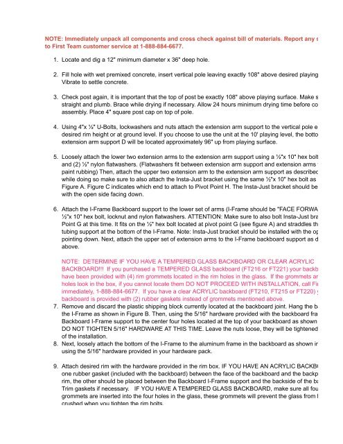
H (1) Lift SpringP(4) 5/16" LockwasherQ(4) 5/16" Hex NutNOTE: Immediately unpack all components and cross check against bill of materials. Report any shortagesto First Team customer service at 1-888-884-6677.1.Locate and dig a 12" minimum diameter x 36" deep hole.2.3.4.5.6.7.8.9.10.Fill hole with wet premixed concrete, insert vertical pole leaving exactly 108" above desired playing surface.Vibrate to settle concrete.Check post again, it is important that the top of post be exactly 108" above playing surface. Make sure post isstraight and plumb. Brace while drying if necessary. Allow 24 hours minimum drying time before continuingassembly. Place 4" square post cap on top of pole.Using 4"x ½" U-Bolts, lockwashers and nuts attach the extension arm support to the vertical pole either atdesired rim height or at ground level. If you choose to use the unit at the 10' playing level, the bottom ofextension arm support D will be located approximately 96" up from playing surface.Loosely attach the lower two extension arms to the extension arm support using a ½"x 10" hex bolt, ½" locknand (2) ½" nylon flatwashers. (Flatwashers fit between extension arm support and extension arms to preventpaint rubbing) Then, attach the upper two extension arm to the extension arm support as described above,while doing so make sure to also attach the Insta-Just bracket using the same ½"x 10" hex bolt as shown onFigure A. Figure C indicates which end to attach to Pivot Point H. The Insta-Just bracket should be installedwith the open side facing down.Attach the I-Frame Backboard support to the lower set of arms (I-Frame should be "FACE FORWARD") using½"x 10" hex bolt, locknut and nylon flatwashers. ATTENTION: Make sure to also bolt Insta-Just bracket to PivPoint G at this time. It fits on the ½" hex bolt located at pivot point G (see figure A) and straddles the 1" squartubing support at the bottom of the I-Frame. Note: Insta-Just bracket should be installed with the open sidepointing down. Next, attach the upper set of extension arms to the I-Frame backboard support as describedabove.NOTE: DETERMINE IF YOU HAVE A TEMPERED GLASS BACKBOARD OR CLEAR ACRYLICBACKBOARD!!! If you purchased a TEMPERED GLASS backboard (FT216 or FT221) your backboard shouhave been provided with (4) rim grommets located in the rim holes in the glass. If the grommets are not in thholes look in the box, if you cannot locate them DO NOT PROCEED WITH INSTALLATION, call First Teamimmediately, 1-888-884-6677. If you have a clear ACRYLIC backboard (FT210, FT215 or FT220) yourbackboard is provided with (2) rubber gaskets instead of grommets mentioned above.Remove and discard the plastic shipping block currently located at the backboard joint. Hang the backboardthe I-Frame as shown in Figure B. Then, using the 5/16" hardware provided with the backboard frame, bolt thBackboard I-Frame support to the center four holes located at the top of your backboard as shown in FigureDO NOT TIGHTEN 5/16" HARDWARE AT THIS TIME. Leave the nuts loose, they will be tightened at the endof the installation.Next, loosely attach the bottom of the I-Frame to the aluminum frame in the backboard as shown in Figure Busing the 5/16" hardware provided in your hardware pack.Attach desired rim with the hardware provided in the rim box. IF YOU HAVE AN ACRYLIC BACKBOARD plaone rubber gasket (included with the backboard) between the face of the backboard and the backplate of therim, the other should be placed between the Backboard I-Frame support and the backside of the backboard.Trim gaskets if necessary. IF YOU HAVE A TEMPERED GLASS BACKBOARD, make sure all four rimgrommets are inserted into the four holes in the glass, these grommets will prevent the glass from beingcrushed when you tighten the rim bolts.Tighten the 5/16" hardware holding the I-Frame Backboard Support to the Aluminum Backboard framediscussed above in step 7 & 8. (see Figure B) It is best to tighten the four 5/16" bolts at the bottom of thebackboard before doing the top.