

LH 30 M - Liebherr
LH 30 M - Liebherr
LH 30 M - Liebherr

You also want an ePaper? Increase the reach of your titles
YUMPU automatically turns print PDFs into web optimized ePapers that Google loves.
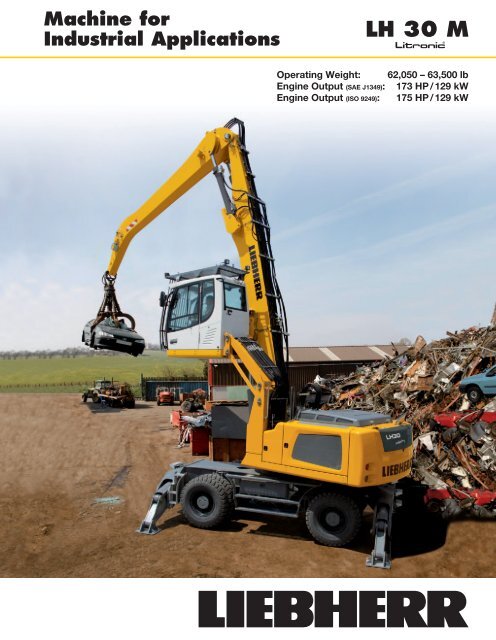
Technical DataEngineRating per SAE J1349 173 HP (129 kW) at 1,800 rpmRating per ISO 9249 175 HP (129 kW) at 1,800 rpmModel <strong>Liebherr</strong> D934 according to stage IIIB / Tier 4iType 4 cylinder in-lineBore/Stroke 4.8/5.9 inDisplacement 427,17 in 3Engine operation 4-stroke dieselCommon-Railturbo-charged and after-cooledreduced emissionsHarmful emissions values in accordance with EPA/CARB-40CFR stage Tier 4 interimEmission control <strong>Liebherr</strong> particle filterCooling water-cooled with integrated motor oil coolerAir cleaner dry-type air cleaner with pre-cleaner, primaryand safety elementsFuel tank 127 galEngine idling sensor controlledElectrical systemVoltage 24 VBatteries 2 x 135 Ah/12 VAlternator three phase current 28 V/100 AHydraulic SystemHydraulic pumpfor attachmentand travel drive two <strong>Liebherr</strong> variable flow, swashplate pumps (doubleconstruction)Max. flow 2 x 57 gpmMax. pressure 5,076 psiHydraulic pumpregulation and control <strong>Liebherr</strong>-Synchron-Comfort-system (LSC) with electronicengine speed sensing regulation, pressure andflow compensation, load sensing and torque controlledswing drive priorityHydraulic tank 50 galHydraulic system 114 galHydraulic oil filter 1 main return filter with integrated partial micro filtration(5 µm)Hydraulic oil cooler compact cooling system consisting cooling unit forwater, hydraulic oil and charge air with steplessthermostatically controlled fanMODE selection adjustment of engine and hydraulic performance via amode pre-selector to match application, e.g. for especiallyeconomical and environmentally friendly operationor for maximum material handling and heavy-dutyjobsS (Sensitive) for precision work and lifting through very sensitivemovementsE (ECO) for especially economical and environmentally friendlyoperationP (Power) for maximum digging power and heavy duty jobsP+ (Power-Plus) for highest performance and for very heavy dutyapplications, suitable for continuous operationEngine speed andperformance setting stepless alignment of engine output and hydraulicpower via engine speedTool Control (Option) ten preadjustable pump flows and pressures for add ontoolsHydraulic ControlsPower distribution via control valve with integrated safety valves, simultaneousand independent operation of travel drive, swingdrive and workServo circuitAttachment and swing with hydraulic pilot control and proportional joystickleversTravel electroproportional via foot pedalAdditional functions via switch or electroproportional foot pedalsOption proportional control, proportionally acting transmitterson the joysticks for additional hydraulic functionsSwing DriveDrive <strong>Liebherr</strong> swashplate motor with torque control andintegrated brake valveTransmission <strong>Liebherr</strong> planetary reduction gearSwing ring <strong>Liebherr</strong>, sealed single race ball bearing swing ring,internal teethSwing speed 0 – 8 rpm steplessSwing torque 55,317 lbf ftBrake holding brake (spring applied – pressure released)Option pedal controlled positioning swing brakeUppercarriageType slewing platform made from high-strength steel plate,designed for the toughest requirementsOperator’s CabCab ROPS safety cab structure (capable of sweeping over)with individual windscreens or featuring a slide-in subpartunder the ceiling, work headlights inte grated in theceiling, a door with a side window (can be opened onboth sides), large stowing and depositing possibilities,shock-absorbing suspension, sounddamping insulating,tinted laminated safety glass, separate shades for thesunroof window and windscreenOperator’s seat Standard air cushioned operator’s seat with headrest, lap belt,seat heater, manual weight adjustment, adjustable seatcushion inclination and length and mechanical lumbarvertebrae supportOperator’s seat Comfort (Option) in addition to operator’s seat standard: lockable horizontalsuspension, automatic weight adjustment,adjustable suspension stiffness, pneumatic lumbarvertebrae support and passive seat climatisation withactive coalOperator’s seat Premium (Option) in addition to operator’s seat comfort: active elec tronicweight adjustment (automatic readjustment), pneumaticlow frequency suspension and active seat climatisationwith active coal and ventilatorControl system joysticks with arm consoles and swivel seatOperation and displays large high-resolution operating unit, selfexplanatory,colour display with touchscreen, video-compatible,numerous setting, control and monitoring options,e.g. air conditioning control, fuel consumption, machineand tool parametersAir-conditioning automatic air-conditioning, recirculated air function,fast de-icing and demisting at the press of a button,air vents can be operated via a menu; recirculated airand fresh air filters can be easily replaced and areaccessible from the outside; heating-cooling unit,designed for extreme out-side temperatures, sensorsNoise emissionfor solar radiation, inside and outside temperaturesISO 6396 L pA (inside cab) = 71 dB(A)2000/14/EC L WA (surround noise) = 102 dB(A)UndercarriageType torsion-resistant box design made from high-strengthsteel plate, designed for the toughest requirementsDrive <strong>Liebherr</strong> variable flow swashplate motor with auto maticbrake valveTransmission oversized two speed power shift trans mission withadditional creeper speedTravel speed 0 – 2.2 mph stepless (creeper speed +transmission stage 1)0 – 4.3 mph stepless (transmission stage 1)0 – 8.1 mph stepless (creeper speed +transmission stage 2)0 – 12.4 mph stepless (transmission stage 2)Driving operation automotive driving using accelerator pedal, cruisecontrol function: storage of variable accelerator pedalpositionsAxles 88,185 lb drive axles; manual or automatic hydraulicallycontrolled front axle oscillation lockService brake two circuit travel brake system with accumulator;maintenance-free, wet and backlash-free disc brakeHolding brake wet, maintenance-free multi disc brakesStabilization 4 point outriggersOption blade, at the front, for 4 point outriggersAttachmentType high-strength steel plates at highlystressed pointsfor the toughest requirements. Complex and stablemountings of attachment and cylindersHydraulic cylinders <strong>Liebherr</strong> cylinders with special seal system.Shock absorptionBearings sealed, low maintenanceComplete MachineLubrication central lubrication system for uppercarriage andattachment, automatically2 <strong>LH</strong> <strong>30</strong> M Litronic Machine for Industrial Applications
Attachment AF1035<strong>30</strong>25121110987H0044Operating WeightThe operating weight includes basic machine with 4 point outriggers,hydr. cab elevation, 8 solid tires plus intermediate rings, industrial-typeangled mono boom 21’4” and industrial-type flat angled stick 13’1”.with clamshell model GM 20B/1.70 yd 3shells for loose material62,050 lb2015654Dimensions1035219'4"10'9"00-5-1-232'8"22'8"US_H0183-10-3-15-4-5-20ft-6m 1211 10 9 8 7 6 5 4 3 210m35<strong>30</strong>2520151050 ftIndustrial Stick 13’1” 10 ft 15 ft 20 ft 25 ft <strong>30</strong> ft 35 ft 40 ftft Undercarriage ft in45Stabilizers raised4 pt. outriggers down40Stabilizers raised4 pt. outriggers down35Stabilizers raised16,7* 16,7* 14,8* 14,8*4 pt. outriggers down16,7* 16,7* 14,8* 14,8*16’ 4”– 10Stabilizers raised4 pt. outriggers down<strong>30</strong>Stabilizers raised20,0 20,6* 12,7 16,7 9,9 12,7*4 pt. outriggers down20,6* 20,6* 17,7* 17,7* 12,7* 12,7*23’ 1”25Stabilizers raised19,9 20,7* 12,7 16,7 8,8 11,6 7,5 9,94 pt. outriggers down20,7* 20,7* 17,6* 17,6* 15,5* 15,5* 12,0* 12,0*27’ 5”20Stabilizers raised19,2 22,2* 12,3 16,3 8,6 11,4 6,3 8,4 6,2 8,34 pt. outriggers down22,2* 22,2* 18,3* 18,3* 15,6* 15,6* 12,5* 12,5* 11,9* 11,9*<strong>30</strong>’ 2”15Stabilizers raised 33,4 36,0* 17,8 24,3 11,6 15,5 8,2 11,0 6,1 8,3 5,5 7,54 pt. outriggers down 36,0* 36,0* 24,9* 24,9* 19,5* 19,5* 16,1* 16,1* 12,4 13,7* 11,2 12,1*32’10Stabilizers raised 16,8* 16,8* 15,9 22,2 10,7 14,6 7,8 10,6 5,9 8,1 5,1 7,04 pt. outriggers down 16,8* 16,8* 27,9* 27,9* 20,7* 20,7* 16,0 16,6* 12,2 13,7* 10,6 12,2*32’11”5Stabilizers raised 7,3* 7,3* 14,3 20,5 9,9 13,7 7,3 10,1 5,7 7,8 4,9 6,84 pt. outriggers down 7,3* 7,3* 28,9* 28,9* 21,2* 21,2* 15,5 16,7* 11,9 13,4* 10,4 11,6*33’0Stabilizers raised 10,3* 10,3* 13,5 19,5 9,3 13,1 7,0 9,7 5,5 7,6 5,0 6,94 pt. outriggers down 10,3* 10,3* 25,8* 25,8* 20,5* 20,5* 15,1 16,0* 11,7 12,5* 10,5 10,8*32’ 4”– 5Stabilizers raised13,3 19,3 9,1 12,8 6,8 9,5 5,4 7,5 5,2 7,34 pt. outriggers down23,0* 23,0* 18,1* 18,1* 14,2* 14,2* 10,5* 10,5* 9,8* 9,8*<strong>30</strong>’11”Height Can be slewed through 360° In longitudinal position of undercarriage Max. reach * Limited by hydr. capacityThe lift capacities on the stick end without attachment are stated in lb x 1,000 and are valid on a firm, level supporting surface with blocked oscillatingaxle. These capacities can be slewed through 360° with the undercarriage in the transverse position. Capacities in the longitudinal position of theundercarriage (+/– 15°) are specified over the steering axle with the stabilizers raised and over the rigid axle with the stabilizers down. Indicated loadscomply with the ISO 10567 standard and do not exceed 75 % of tipping or 87 % of hydraulic capacity.The lift capacity of the unit is limited by itsstability, the lifting capability of the hydraulic elements, or the maximum permissible lifting capacity of the load hook.4 <strong>LH</strong> <strong>30</strong> M Litronic Machine for Industrial Applications
Attachment GA12454035<strong>30</strong>14131211109H0047Operating WeightThe operating weight includes basic machine with 4 point outriggers,hydr. cab elevation, 8 solid tires plus intermediate rings, industrial-typestraight mono boom 22’4” and industrial-type angled stick 16’5”.with grapple model GM 65/0.78 yd 3 semi-closed tines 62,400 lb2520876Dimensions15105543219'8"10'9"0-50-1-233'8"22'US_H0185-10-3-15-4-5-20ft-6m 141312 11 10 9 8 7 6 5 4 3 2 10 m454035<strong>30</strong>2520151050 ftIndustrial Stick 16’5” 10 ft 15 ft 20 ft 25 ft <strong>30</strong> ft 35 ft 40 ftft Undercarriage ft in45Stabilizers raised4 pt. outriggers down40Stabilizers raised4 pt. outriggers down17,8* 17,8* 13,9* 13,9*18’ 2”35Stabilizers raised12,8 16,8 8,6 11,5 8,3 11,04 pt. outriggers down17,4* 17,4* 12,3* 12,3* 11,3* 11,3*25’ 6”<strong>30</strong>Stabilizers raised13,0 17,1 9,0 11,8 6,3 8,5 6,2 8,34 pt. outriggers down17,4* 17,4* 15,2* 15,2* 10,8* 10,8* 10,1* 10,1*<strong>30</strong>’ 4”25Stabilizers raised12,9 16,9 8,9 11,8 6,5 8,6 5,1 7,04 pt. outriggers down17,5* 17,5* 15,2* 15,2* 12,8 13,3* 9,6* 9,6*33’ 7”20Stabilizers raised19,6 22,0* 12,4 16,4 8,7 11,5 6,3 8,5 4,7 6,5 4,5 6,24 pt. outriggers down22,0* 22,0* 18,2* 18,2* 15,5* 15,5* 12,7 13,4* 9,8 11,5* 9,3* 9,3*36’15Stabilizers raised 21,7* 21,7* 18,1 24,7 11,7 15,6 8,2 11,0 6,1 8,3 4,7 6,4 4,1 5,74 pt. outriggers down 21,7* 21,7* 24,7* 24,7* 19,4* 19,4* 16,0* 16,0* 12,4 13,5* 9,7 11,4* 8,7 9,3*37’ 6”10Stabilizers raised 29,3 42,6* 16,1 22,5 10,7 14,6 7,7 10,5 5,8 7,9 4,5 6,2 3,9 5,44 pt. outriggers down 42,6* 42,6* 27,5* 27,5* 20,5* 20,5* 15,9 16,4* 12,1 13,6* 9,5 11,2* 8,3 9,4*38’ 2”5Stabilizers raised 5,5* 5,5* 14,2 20,4 9,7 13,5 7,2 9,9 5,5 7,6 4,3 6,1 3,8 5,34 pt. outriggers down 5,5* 5,5* 28,7* 28,7* 21,0* 21,0* 15,3 16,5* 11,7 13,3* 9,4 10,7* 8,2 8,5*38’ 5”0Stabilizers raised 6,4* 6,4* 13,1 19,1 9,0 12,8 6,7 9,5 5,3 7,4 4,2 6,0 3,8 5,44 pt. outriggers down 6,4* 6,4* 21,2* 21,2* 20,2* 20,2* 14,8 15,7* 11,5 12,5* 9,2 9,6* 7,4* 7,4*37’10”17,8* 17,8* 13,9* 13,9*Stabilizers raised12,6 18,6 8,7 12,4 6,5 9,2 5,1 7,2 4,2 5,9 4,1 5,8– 5 4 pt. outriggers down19,8* 19,8* 17,8* 17,8* 14,0* 14,0* 10,9* 10,9* 7,6* 7,6* 7,0* 7,0*Stabilizers raised– 10 4 pt. outriggers down8,6 12,3 6,4 9,1 5,5 7,713,9* 13,9* 11,0* 11,0* 9,1* 9,1*Height Can be slewed through 360° In longitudinal position of undercarriage Max. reach * Limited by hydr. capacityThe lift capacities on the stick end without attachment are stated in lb x 1,000 and are valid on a firm, level supporting surface with blocked oscillatingaxle. These capacities can be slewed through 360° with the undercarriage in the transverse position. Capacities in the longitudinal position of theundercarriage (+/– 15°) are specified over the steering axle with the stabilizers raised and over the rigid axle with the stabilizers down. Indicated loadscomply with the ISO 10567 standard and do not exceed 75 % of tipping or 87 % of hydraulic capacity.The lift capacity of the unit is limited by itsstability, the lifting capability of the hydraulic elements, or the maximum permissible lifting capacity of the load hook.35’ 8”28’ 5”6 <strong>LH</strong> <strong>30</strong> M Litronic Machine for Industrial Applications
Attachment GK12501615H0051Operating Weight454035<strong>30</strong>14131211109The operating weight includes basic machine with 4 point outriggers,hydr. cab elevation, 8 solid tires plus intermediate rings, industrial-typestraight mono boom 22’4” and industrial-type stick with tipping kinematics16’5”.with sorting grab SG <strong>30</strong>/1.11 yd 3 tines63,500 lb2520876Dimensions151050-5543210-1-29'2"33'8"18'10"US_H018810'9"-10-3-15-4-5-20ft-6m 161514 13 12 11 10 9 8 7 6 5 4 3 2 10m50454035<strong>30</strong>2520151050ftIndustrial Stick 16’5” 10 ft 15 ft 20 ft 25 ft <strong>30</strong> ft 35 ft 40 ftft Undercarriage ft in45Stabilizers raised4 pt. outriggers down40Stabilizers raised4 pt. outriggers down19,2* 19,2* 14,0* 14,0*19’ 2”35Stabilizers raised12,2 16,3 8,0 10,8 7,2 9,84 pt. outriggers down17,2* 17,2* 13,6* 13,6* 11,1* 11,1*26’ 4”<strong>30</strong>Stabilizers raised12,5 16,5 8,4 11,2 5,7 7,9 5,3 7,44 pt. outriggers down16,7* 16,7* 14,5* 14,5* 12,0* 12,0* 9,8* 9,8*<strong>30</strong>’11”25Stabilizers raised12,3 16,4 8,3 11,2 5,9 8,0 4,3 6,14 pt. outriggers down16,8* 16,8* 14,5* 14,5* 12,2 12,6* 9,1* 9,1*34’ 2”20Stabilizers raised19,1 19,6* 11,9 15,9 8,1 10,9 5,7 7,9 4,1 5,9 3,7 5,44 pt. outriggers down19,6* 19,6* 17,5* 17,5* 14,8* 14,8* 12,1 12,7* 9,2 10,8* 8,5 8,8*36’ 6”15Stabilizers raised 15,5* 15,5* 17,6 23,9* 11,1 15,0 7,6 10,4 5,5 7,7 4,0 5,8 3,3 4,94 pt. outriggers down 15,5* 15,5* 23,9* 23,9* 18,7* 18,7* 15,3* 15,3* 11,8 12,8* 9,1 10,7* 7,9 8,6*38’10Stabilizers raised 28,6 28,8* 15,5 21,8 10,1 13,9 7,1 9,8 5,2 7,3 3,9 5,6 3,1 4,74 pt. outriggers down 28,8* 28,8* 26,7* 26,7* 19,8* 19,8* 15,3 15,7* 11,5 12,8* 8,9 10,5* 7,5 8,2*38’ 8”5Stabilizers raised13,5 19,6 9,1 12,9 6,5 9,3 4,9 7,0 3,7 5,5 3,1 4,64 pt. outriggers down27,9* 27,9* 20,2* 20,2* 14,7 15,7* 11,1 12,6* 8,7 9,9* 7,2* 7,2*38’10”0Stabilizers raised 3,7* 3,7* 12,3 17,5* 8,3 12,1 6,1 8,8 4,6 6,7 3,6 5,3 3,1 4,74 pt. outriggers down 3,7* 3,7* 17,5* 17,5* 19,4* 19,4* 14,2 15,0* 10,8 11,7* 8,6 8,8* 6,1* 6,1*38’ 4”18,8 19,2* 12,0 14,0*Stabilizers raised11,9 17,3* 7,9 11,7 5,8 8,5 4,5 6,6 3,5 5,3 3,5 5,1– 5 4 pt. outriggers down17,3* 17,3* 17,0* 17,0* 13,2* 13,2* 10,1* 10,1* 6,8* 6,8* 6,3* 6,3*Stabilizers raised– 10 4 pt. outriggers down7,9 11,6 5,7 8,4 4,8 7,113,1* 13,1* 10,2* 10,2* 8,3* 8,3*Height Can be slewed through 360° In longitudinal position of undercarriage Max. reach * Limited by hydr. capacityThe lift capacities on the stick end without attachment are stated in lb x 1,000 and are valid on a firm, level supporting surface with blocked oscillatingaxle. These capacities can be slewed through 360° with the undercarriage in the transverse position. Capacities in the longitudinal position of theundercarriage (+/– 15°) are specified over the steering axle with the stabilizers raised and over the rigid axle with the stabilizers down. Indicated loadscomply with the ISO 10567 standard and do not exceed 75 % of tipping or 87 % of hydraulic capacity.The lift capacity of the unit is limited by itsstability, the lifting capability of the hydraulic elements, or the maximum permissible lifting capacity of the load hook.35’ 8”28’ 5” <strong>LH</strong> <strong>30</strong> M Litronic Machine for Industrial Applications 7
Attachment GA1350454035<strong>30</strong>2520161514131211109876H0046Operating WeightThe operating weight includes basic machine with 4 point outriggers,hydr. cab elevation, 8 solid tires plus intermediate rings, industrial-typestraight mono boom 23’11” and industrial-type angled stick 18’1”.with grapple model GM 65/0.78 yd 3 semi-closed tines 62,850 lbDimensions15105054321010'4"35'3"22'10'9"US_H0186-5-1-2-10-15-20-3-4-5-6-25ft-7-8m141312 11 10 9 8 7 6 5 4 3 2 10 m454035<strong>30</strong>2520151050 ftIndustrial Stick 18’1” 10 ft 15 ft 20 ft 25 ft <strong>30</strong> ft 35 ft 40 ftft Undercarriage ft in45Stabilizers raised15,0* 15,0*4 pt. outriggers down15,0* 15,0*14’11”Stabilizers raised7,9 11,6 5,9 8,6 4,6 6,7 3,9 5,7– 10 34’4 pt. outriggers down 14,3* 14,3* 11,6* 11,6* 9,0* 9,0* 6,9* 6,9*40Stabilizers raised12,8 15,5* 8,9 11,1*4 pt. outriggers down15,5* 15,5* 11,1* 11,1*24’ 5”35Stabilizers raised13,3 16,7* 9,1 11,9 6,3 8,5 6,2 8,44 pt. outriggers down16,7* 16,7* 14,6* 14,6* 10,0* 10,0* 9,6* 9,6*<strong>30</strong>’ 2”<strong>30</strong>Stabilizers raised13,4 16,5* 9,2 12,1 6,6 8,8 4,9 6,74 pt. outriggers down16,5* 16,5* 14,3* 14,3* 12,7* 12,7* 8,9* 8,9*34’ 4”25Stabilizers raised13,1 16,8* 9,0 11,9 6,5 8,7 4,8 6,6 4,1 5,84 pt. outriggers down16,8* 16,8* 14,5* 14,5* 12,7* 12,7* 9,9 11,2* 8,5* 8,5*37’ 4”20Stabilizers raised12,5 16,6 8,7 11,5 6,3 8,5 4,7 6,5 3,7 5,24 pt. outriggers down17,6* 17,6* 14,9* 14,9* 12,7 12,8* 9,8 11,2* 8,0 8,3*39’ 5”15Stabilizers raised 18,0* 18,0* 18,2 24,1* 11,6 15,6 8,1 11,0 6,0 8,2 4,6 6,3 3,5 5,0 3,3 4,84 pt. outriggers down 18,0* 18,0* 24,1* 24,1* 18,8* 18,8* 15,4* 15,4* 12,4 13,0* 9,6 11,1* 7,7 9,3* 7,5 8,3*40’10”10Stabilizers raised 28,7 32,0* 15,8 22,2 10,5 14,4 7,5 10,3 5,6 7,8 4,3 6,1 3,4 4,9 3,2 4,64 pt. outriggers down 32,0* 32,0* 26,8* 26,8* 19,9* 19,9* 15,8 15,9* 11,9 13,2* 9,4 11,0* 7,6 9,0* 7,2 8,2*41’ 6”5Stabilizers raised 3,9* 3,9* 13,6 19,7 9,3 13,2 6,9 9,6 5,3 7,4 4,1 5,9 3,3 4,7 3,1 4,54 pt. outriggers down 3,9* 3,9* 27,9* 27,9* 20,4* 20,4* 15,1 16,0* 11,5 13,0* 9,2 10,7* 7,5 8,4* 7,1 7,4*41’ 7”0Stabilizers raised 4,8* 4,8* 12,3 16,0* 8,5 12,3 6,4 9,1 4,9 7,0 3,9 5,7 3,2 4,7 3,1 4,54 pt. outriggers down 4,8* 4,8* 16,0* 16,0* 19,8* 19,8* 14,5 15,5* 11,1 12,4* 8,9 10,0* 7,3* 7,3* 6,5* 6,5*41’ 1”– 5Stabilizers raised11,7 15,3* 8,0 11,8 6,0 8,7 4,7 6,8 3,8 5,5 3,3 4,74 pt. outriggers down15,3* 15,3* 17,7* 17,7* 14,0* 14,0* 10,9 11,2* 8,6* 8,6* 5,9* 5,9*39’ 5”Height Can be slewed through 360° In longitudinal position of undercarriage Max. reach * Limited by hydr. capacityThe lift capacities on the stick end without attachment are stated in lb x 1,000 and are valid on a firm, level supporting surface with blocked oscillatingaxle. These capacities can be slewed through 360° with the undercarriage in the transverse position. Capacities in the longitudinal position of theundercarriage (+/– 15°) are specified over the steering axle with the stabilizers raised and over the rigid axle with the stabilizers down. Indicated loadscomply with the ISO 10567 standard and do not exceed 75 % of tipping or 87 % of hydraulic capacity.The lift capacity of the unit is limited by itsstability, the lifting capability of the hydraulic elements, or the maximum permissible lifting capacity of the load hook.8 <strong>LH</strong> <strong>30</strong> M Litronic Machine for Industrial Applications
Attachment GA1450454035<strong>30</strong>2520161514131211109876H0048Operating WeightThe operating weight includes basic machine with 4 point outriggers,hydr. cab elevation, 8 solid tires plus intermediate rings, industrial-typestraight mono boom 25’7” and industrial-type angled stick 19’8”.with grapple model GM 65/0.78 yd 3 semi-closed tines 63,250 lbDimensions151050-5-10-15543210-1-2-3-4-510'10"36'11"22'10'9"US_H0187-20-25ft-6-7-8m 16 15 14 13 12 11 10 9 8 7 6 5 4 3 2 10m50454035<strong>30</strong>2520151050ftIndustrial Stick 19’8” 10 ft 15 ft 20 ft 25 ft <strong>30</strong> ft 35 ft 40 ftft Undercarriage ft in45Stabilizers raised12,6 13,6* 10,1 11,2*4 pt. outriggers down13,6* 13,6* 11,2* 11,2*22’ 7”Stabilizers raised10,7 13,7* 7,2 10,9 5,4 8,1 4,2 6,3 3,4 5,1 3,0 4,5– 10 38’ 8”4 pt. outriggers down 13,7* 13,7* 14,5* 14,5* 11,8* 11,8* 9,5* 9,5* 7,3* 7,3* 5,6* 5,6*40Stabilizers raised13,4 15,8* 9,1 12,0 6,4 8,74 pt. outriggers down15,8* 15,8* 13,5* 13,5* 9,3* 9,3*29’ 7”35Stabilizers raised13,7 15,9* 9,4 12,3 6,7 8,9 4,8 6,64 pt. outriggers down15,9* 15,9* 13,8* 13,8* 12,2* 12,2* 8,4* 8,4*34’ 7”<strong>30</strong>Stabilizers raised9,4 12,3 6,7 9,0 4,9 6,7 3,9 5,54 pt. outriggers down13,7* 13,7* 12,1* 12,1* 10,0 10,7* 7,9* 7,9*38’ 2”25Stabilizers raised13,4 16,2* 9,2 12,1 6,6 8,8 4,9 6,6 3,6 5,1 3,4 4,84 pt. outriggers down16,2* 16,2* 13,9* 13,9* 12,2* 12,2* 10,0 10,7* 7,8 9,2* 7,5 7,6*40’11”20Stabilizers raised12,7 16,7 8,7 11,6 6,3 8,5 4,7 6,5 3,5 5,0 3,0 4,34 pt. outriggers down17,1* 17,1* 14,4* 14,4* 12,4* 12,4* 9,8 10,8* 7,8 9,3* 6,9 7,5*42’10”15Stabilizers raised 15,0* 15,0* 18,2 21,8* 11,6 15,6 8,1 10,9 5,9 8,1 4,5 6,2 3,4 4,9 2,7 4,04 pt. outriggers down 15,0* 15,0* 21,8* 21,8* 18,3* 18,3* 15,0* 15,0* 12,3 12,6* 9,6 10,8* 7,7 9,2* 6,5 7,5*44’ 1”10Stabilizers raised 21,3* 21,3* 15,6 21,9 10,3 14,2 7,3 10,1 5,5 7,6 4,2 5,9 3,3 4,7 2,6 3,84 pt. outriggers down 21,3* 21,3* 26,2* 26,2* 19,4* 19,4* 15,5* 15,5* 11,8 12,8* 9,3 10,8* 7,5 9,0* 6,2 7,1*44’ 8”5Stabilizers raised 2,7* 2,7* 13,1 19,2 9,0 12,8 6,6 9,3 5,0 7,2 3,9 5,7 3,1 4,6 2,5 3,84 pt. outriggers down 2,7* 2,7* 22,6* 22,6* 19,9* 19,9* 14,8 15,6* 11,3 12,7* 9,0 10,5* 7,3 8,7* 6,1 6,5*44’10”0Stabilizers raised 3,6* 3,6* 11,5 12,4* 8,0 11,8 6,0 8,7 4,6 6,8 3,7 5,4 2,9 4,4 2,5 3,84 pt. outriggers down 3,6* 3,6* 12,4* 12,4* 19,3* 19,3* 14,1 15,1* 10,8 12,2* 8,7 10,0* 7,2 8,0* 5,7* 5,7*44’ 5”– 5Stabilizers raised 5,8* 5,8* 10,9 12,1* 7,5 11,2 5,6 8,3 4,4 6,5 3,5 5,2 2,9 4,3 2,6 3,94 pt. outriggers down 5,8* 5,8* 12,1* 12,1* 17,4* 17,4* 13,6 13,9* 10,5 11,2* 8,5 9,0* 6,8* 6,8* 4,9* 4,9*43’ 1”Height Can be slewed through 360° In longitudinal position of undercarriage Max. reach * Limited by hydr. capacityThe lift capacities on the stick end without attachment are stated in lb x 1,000 and are valid on a firm, level supporting surface with blocked oscillatingaxle. These capacities can be slewed through 360° with the undercarriage in the transverse position. Capacities in the longitudinal position of theundercarriage (+/– 15°) are specified over the steering axle with the stabilizers raised and over the rigid axle with the stabilizers down. Indicated loadscomply with the ISO 10567 standard and do not exceed 75 % of tipping or 87 % of hydraulic capacity.The lift capacity of the unit is limited by itsstability, the lifting capability of the hydraulic elements, or the maximum permissible lifting capacity of the load hook. <strong>LH</strong> <strong>30</strong> M Litronic Machine for Industrial Applications 9
Variety of ToolsShells for loose material withShells for Loose Materialcutting edge (without teeth)Clamshell Model GM 20BCutting width of shells ft in 3’3” 3’11” 5’3”Capacity yd 3 1.70 1.96 2.62For loose material, specific weight up to lb/yd 3 2,528 2,528 2,528Weight lb 2,987 3,120 3,417Multiple Tine Grapples open tines semi-closed tines closed tinesGrapple Model GM 65 (5 tines)Capacity yd 3 0.52 0.78 0.52 0.78 0.52 0.78Weight lb 2,535 2,712 2,833 3,120 2,921 3,351Wood GrappleGrapple Model GB 20BClaw width ft in 2’8” 2’8” 2’8”Size in 2 2,015 2,635 3,255Height of grapple, closed ft in 9’8” 10’ 10’10”Weight lb 3,693 3,913 4,299with with with withribbed perforated ribbed perforatedSorting Grappleshells shells shells shellsGrapple Model SG <strong>30</strong>Cutting width of shells ft in 3’3” 3’3” 3’9” 3’9”Capacity yd 3 0.98 1.11 1.18 1.31Max. closing force lb 17,640 17,640 17,640 17,640Weight incl. adapter plate lb 3,595 3,550 3,770 3,725Crane Hook with SuspensionMax. load lb 27,558Height with suspension ft in 3’1”Weight lb 212Magnet Devices/Lifting MagnetsGenerator kW 13/17 13/17Electromagnets with SuspensionPower kW 8.8 8.5/10Diameter of magnet ft in 4’1” 4’5”Weight lb 2,888 3,74810 <strong>LH</strong> <strong>30</strong> M Litronic Machine for Industrial Applications
EquipmentUndercarriageSupport rocker, variants +Individual control outriggers +Shuttle axle lock, automatic•Dozer blade +Outrigger monitoring system +Tyres, variants +Protection for travel drive +Protection for piston rods, outriggers +Tool equipment, extended +Two lockable storage boxes•UppercarriageRefuelling system with filling pump +Railing on uppercarriage +Generator +Main battery switch for electrical system•Protection for headlights +Protection for rear lights +HydraulicsElectronic pump regulation•<strong>Liebherr</strong> hydraulic oil from – 4 °F to + 104 °F•<strong>Liebherr</strong> hydraulic oil, biologically degradable +Magnetic rod in hydraulic tank•Bypass filter +Preheating hydraulic oil +EngineFuel anti-theft device +<strong>Liebherr</strong> particle filter•Reversible fan drive, fully automatic +Air pre-filter with dust discharge +Protective grid in front of cooler intake•Preheating fuel +Preheating coolant +Preheating engine oil +Operator’s CabCab lights rear, halogen +Cab lights rear, LED 1<strong>30</strong>0 lumen +Cab lights front, halogen•Cab lights front, LED 1<strong>30</strong>0 lumen +Operator’s seat Standard•Operator’s seat Comfort +Operator’s seat Premium +Driving alarm (acoustic signal is emitted during travel,can be switched ON/OFF) +Fire extinguisher +Joystick steering +Cab elevation, hydraulic (<strong>LH</strong>C) +Cab elevation, rigid (LFC) +Automatic air conditioning•Electric cooler +LiDAT Plus (extended <strong>Liebherr</strong> data transfer system) *•Bullet proof glass +Positioning swing brake +Proportional control +Radio Comfort (control via display) +Preparation for radio installation•Back-up alarm (acoustic signal is emitted traveling backward,can not be switched off) +Warning beacon on cab +Windscreen wiper, roof +Top guard +Front guard +Sun visor +Auxiliary heating, adjustable (week time switch) +Flashing light (xenon) +Electronic immobilizer +AttachmentBoom lights, 2 pieces, halogen•Boom lights, 2 pieces, LED 1<strong>30</strong>0 lumen +Stick lights, 2 pieces, halogen•Stick lights, 2 pieces, LED 1<strong>30</strong>0 lumen, with protection +Boom shutoff, ascending +AutoLift +Height limitation and stick shutoff, electronically +Boom cylinder cushioning +Industrial stick with quick coupling +Stick camera (with separate monitor), bottom side, with protection +<strong>Liebherr</strong> multi coupling system +<strong>Liebherr</strong> quick coupler, hydraulic or mechanical +Pipe fracture safety valves hoist cylinders•Pipe fracture safety valve stick cylinder•Quick coupling system LIKUFIX +Quick coupling system MH40/MH110 +Protection for piston rod, hoist cylinder +Overload warning device +Protection for stick +Complete MachineLubricationLubrication undercarriage, manually – decentralized(grease points)•Central lubrication system for uppercarriage and attachment,automatically•Central lubrication system for undercarriage, automatically +Special coatingSingle-coloured, grey parts excepted +Single-coloured, grey parts included (except power train) +Multicoloured (except power train) +MonitoringRear view monitoring with camera•Side view monitoring with camera +• = Standard, + = Option* = optionally extendable after one yearOptions and/or special attachments, supplied by vendors other than <strong>Liebherr</strong>, are only to be installed with theknowledge and approval of <strong>Liebherr</strong> in order to retain warranty. <strong>LH</strong> <strong>30</strong> M Litronic Machine for Industrial Applications 11
The <strong>Liebherr</strong> Group of CompaniesWide Product RangeThe <strong>Liebherr</strong> Group is one of the largest constructionequipment manufacturers in the world. <strong>Liebherr</strong>’shigh-value products and services enjoy a high reputationin many other fields. The wide range includes domesticappliances, aerospace and transportation systems,machine tools and maritime cranes.Exceptional Customer BenefitEvery product line provides a complete range of modelsin many different versions. With both their technicalexcel lence and acknowledged quality, <strong>Liebherr</strong> productsoffer a maximum of customer benefits in practicalapplication.State-of-the-art TechnologyTo provide consistent, top quality products, <strong>Liebherr</strong>attaches great importance to each product area, itscomponents and core technologies. Important modulesand components are developed and manufacturedin-house, for instance the entire drive and controltechno logy for construction equipment and mining trucks.Worldwide and IndependentHans <strong>Liebherr</strong> founded the <strong>Liebherr</strong> family company in1949. Since that time, the enterprise has steadily grownto a group of more than 1<strong>30</strong> companies with over38,000 employees located on all continents. The corporateheadquarters of the Group is <strong>Liebherr</strong>-International AGin Bulle, Switzerland. The <strong>Liebherr</strong> family is the sole ownerof the company.www.liebherr.usPrinted in USA RG-BK-RP <strong>LH</strong>B/VF 11600225-0.5-03.13_enUSAll illustrations and data may differ from standard equipment. Subject to change without notice.<strong>Liebherr</strong> Construction Equipment Co.4100 Chestnut Avenue, Newport News, VA 23607, USA +1 (757) 245 5251, Fax +1 (757) 928 8701www.liebherr.us, E-Mail: info.lce@liebherr.comwww.facebook.com/<strong>Liebherr</strong>Construction