User Manual - ALLSEASONS Heating And Cooling
User Manual - ALLSEASONS Heating And Cooling
User Manual - ALLSEASONS Heating And Cooling

You also want an ePaper? Increase the reach of your titles
YUMPU automatically turns print PDFs into web optimized ePapers that Google loves.
2WARNINGS & SAFETY PRECAUTIONSWHAT TO DO IF YOU SMELL GASW415-0496 / B / 08.10.05
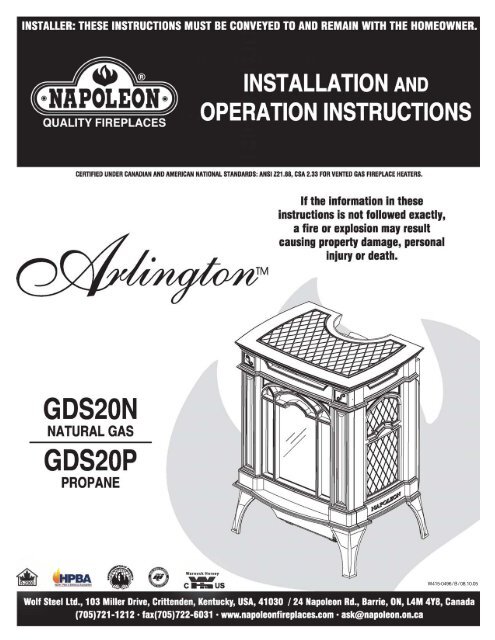
2. Warnings and Safety PrecautionsWhat to do if you smell gas4. Warranty5. General InstructionsGeneral InformationCare of Glass and Plated Parts6. Location and ClearancesPilot Indicator Light - Battery Install7. Blower Installation8. Terminal Installation9. VentingVenting Lengths and Air Terminal Locations10. Typical and Special Vent Installations11. Venting Specifications15. Wall and Ceiling Protection16. Horizontal and Vertical Venting17. Stove Vent ConnectionMobile Home InstallationRestricting Vertical VentsGas InstallationTABLE of CONTENTS18. FinishingGlass door install and removalCast Front Installation and removal19. Logo PlacementLog Placement20. Operation / Maintenance21. AdjustmentsPilot Burner AdjustmentVenturi AdjustmentOrifice Replacement22. ReplacementsReplacement PartsAccessories24. Trouble Shooting26. Service History3PLEASE RETAIN THIS MANUAL FOR FUTURE REFERENCEWARNING• The stove is a vented gas-fired heater. Do not burn wood or other materials in this stove.• Adults and especially children should be alerted to the hazards of high surface temperatures and shouldstay away to avoid burns or clothing ignition. Keep young children and animals away when the stove ishot.• Due to high temperatures, the stove should be located out of traffic and away from furniture and draperies.• Clothing or other flammable material should not be placed on or near the stove.• Any safety screen or guard removed for servicing must be replaced prior to operating the stove.• It is imperative that the control compartments, burners and circulating blower and its passageway in thestove and venting system are kept clean. The stove and its venting system should be inspected before useand at least annually by a qualified service person. More frequent cleaning may be required due to excessivelint from carpeting, bedding material, etc. The stove area must be kept clear and free from combustiblematerials, gasoline and other flammable vapours and liquids.• Under no circumstances should this stove be modified.• This stove must not be connected to a chimney flue pipe serving a separate solid fuel burning appliance.• Do not use this stove if any part has been under water. Immediately call a qualified service technician toinspect the stove and to replace any part of the control system and any gas control which has been underwater.• Do not operate the stove with the glass door opened, cracked or broken. Replacement of the glass shouldbe done by a licensed or qualified service person.• Do not strike or slam shut the stove glass door.• This fireplace uses and requires a fast acting thermocouple. Replace only with a fast acting thermocouplesupplied by Wolf Steel Ltd.NOTE: changes, other than editorial, are denoted by a vertical line in the margin.W415-0496 / B / 08.10.05
4NAPOLEON products are manufactured under the strict Standard of the world recognizedISO 9001 : 2000 Quality Assurance Certificate.NAPOLEON products are designed with superior components and materials, assembled by trained craftsmen who takegreat pride in their work. The burner and valve assembly are leak and test-fired at a quality test station. The completefireplace is test-fired and thoroughly inspected by a qualified technician before packaging to ensure that you, thecustomer, receives the quality product that you expect from NAPOLEON.NAPOLEON GAS FIREPLACE PRESIDENT'S LIFETIME LIMITED WARRANTYThe following materials and workmanship in your new NAPOLEON gas fireplace are warranted against defects foras long as you own the fireplace. This covers: combustion chamber, heat exchanger, stainless steel burner, phazerlogs and embers, ceramic glass (thermal breakage only), gold plated parts against tarnishing, porcelainized enamelledcomponents and aluminium extrusion trims.Electrical (110V and millivolt) components and wearable parts such as catalytic tiles, blowers, gas valves, thermalswitch, switches, wiring, remote controls, ignitor, gasketing, and pilot assembly are covered and NAPOLEON willprovide replacement parts free of charge during the first year of the limited warranty.Any labour related to warranty repair is not covered.CONDITIONS AND LIMITATIONSNAPOLEON warrants its products against manufacturing defects to the original purchaser only -- i.e., the individual or legal entity (registered customer) whose name appears on the warrantyregistration card filed with NAPOLEON -- provided that the purchase was made through an authorized NAPOLEON dealer and is subject to the following conditions and limitations:This factory warranty is nontransferable and may not be extended whatsoever by any of our representatives.The gas fireplace must be installed by a licenced, authorized service technician or contractor. Installation must be done in accordance with the installation instructions included with the productand all local and national building and fire codes.This limited warranty does not cover damages caused by misuse, lack of maintenance, accident, alterations, abuse or neglect and parts installed from other manufacturers will nullify thiswarranty.This limited warranty further does not cover any scratches, dents, corrosion or discolouring caused by excessive heat, abrasive and chemical cleaners nor chipping on porcelain enamelparts, mechanical breakage of PHAZER logs and embers, nor any venting components used in the installation of the fireplace.NAPOLEON warrants its stainless steel burners against defects in workmanship and material for life, subject to the following conditions: During the first 10 years NAPOLEON will replaceor repair the defective parts at our option free of charge. From 10 years to life, NAPOLEON will provide replacement burners at 50% of the current retail price.In the first year only, this warranty extends to the repair or replacement of warranted parts which are defective in material or workmanship provided that the product has been operated inaccordance with the operation instructions and under normal conditions.After the first year, with respect to this President's Limited Lifetime Warranty, NAPOLEON may, at its discretion, fully discharge all obligations with respect to this warranty by refunding tothe original warranted purchaser the wholesale price of any warranted but defective part(s).After the first year, NAPOLEON will not be responsible for installation, labour or any other costs or expenses related to the reinstallation of a warranted part, and such expenses are not coveredby this warranty.Notwithstanding any provisions contained in this President's Limited Lifetime Warranty, NAPOLEON’S responsibility under this warranty is defined as above and it shall not in any event extendto any incidental, consequential or indirect damages.This warranty defines the obligations and liability of NAPOLEON with respect to the NAPOLEON gas fireplace and any other warranties expressed or implied with respect to this product,its components or accessories are excluded.NAPOLEON neither assumes, nor authorizes any third party to assume, on its behalf, any other liabilities with respect to the sale of this product. NAPOLEON will not be responsible for:over-firing, downdrafts, spillage caused by environmental conditions such as rooftops, buildings, nearby trees, hills, mountains, inadequate vents or ventilation, excessive venting configurations,insufficient makeup air, or negative air pressures which may or may not be caused by mechanical systems such as exhaust fans, furnaces, clothes dryers, etc.Any damages to fireplace, combustion chamber, heat exchanger, brass trim or other component due to water, weather damage, long periods of dampness, condensation, damaging chemicalsor cleaners will not be the responsibility of NAPOLEON.The bill of sale or copy will be required together with a serial number and a model number when making any warranty claims from your authorized dealer. The warranty registration card mustbe returned within fourteen days to register the warranty.NAPOLEON reserves the right to have its representative inspect any product or part thereof prior to honouring any warranty claim.ALL SPECIFICATIONS AND DESIGNS ARE SUBJECT TO CHANGE WITHOUT PRIOR NOTICE DUE TO ON-GOING PRODUCT IMPROVEMENTS. NAPOLEON® IS A REGISTEREDTRADEMARK OF WOLF STEEL LTD. PATENTS U.S. 5.303.693.801 - CAN. 2.073.411, 2.082.915. © WOLF STEEL LTD.W415-0496 / B / 08.10.05
5GENERAL INSTRUCTIONSTHIS GAS STOVE SHOULD BE INSTALLED AND SERVICEDBY A QUALIFIED INSTALLER to conform with local codes. Installationpractices vary from region to region and it is important toknow the specifics that apply to your area,for example: in Massachusetts State:• The fireplace damper must be removed or welded in the openposition prior to installation of a fireplace insert or gas log.• The appliance off valve must be a “T” handle gas cock.• The flexible connector must not be longer than 36 inches.• The appliance is not approved for installation in a bedroom orbathroom unless the unit is a direct vent sealed combustionproduct.• WARNING: This product must be installed by a licensed plumberor gas fitter when installed within the commonwealth ofMassachusetts.In absence of local codes, install to the current CAN1-B149Installation Code in Canada or to the National Fuel Gas Code,ANSI Z223.1, and NFPA 54 in the United States. Mobile homeinstallation must conform with local codes. In the absence oflocal codes, install to the current standard for gas equippedmobile housing CAN/CSA Z240 MH Series in Canada or themanufactured home construction and safety standard, Title 24CFR, part 3280, or the Fire Safety Criteria for manufacturedhome installations, Sites and Community Standard ANSI/NFPA501A in the United States.Purge all gas lines with the glass door of the stove removed.Assure that a continuous gas flow is at the burner before reinstallingthe door.Under extreme vent configurations, allow several minutes (5-15) for the flame to stabilize after ignition.It is recommended that all horizontal runs have a ¼ inch riseper foot.Objects placed in front of the stove must be kept a minimumof 48" away from the front face of the unit.The stove and its individual shutoff valve must be disconnectedfrom the gas supply piping system during any pressure testing ofthat system at test pressures in excess of 1/2 psig (3.5 kPa). Thestove must be isolated from the gas supply piping system byclosing its individual manual shutoff valve during any pressuretesting of the gas supply piping system at test pressures equal toor less than ½ psig (3.5 kPa).The stove, when installed with a blower, must be electrically connectedand grounded in accordance with local codes. In the absenceof local codes, use the current CSA C22.1 CANADIANELECTRICAL CODE in Canada or the ANSI/NFPA 70 NATIONALELECTRICAL CODE in the United States. The blower power cordmust be connected into a properly grounded receptacle. Thegrounding prong must not be removed from the cord plug.Expansion / contraction noises during heating up and coolingdown cycles are normal and to be expected.This appliance is only for use with the type of gas indicatedon the rating plate. This appliance is not convertible for usewith other gases, unless a certified kit is used.CARE OF GLASS, AND PLATED PARTSDo not use abrasive cleaners to clean these parts. Bufflightly with a clean dry cloth.The glass is 3 / 16" ceramic glass available from your Napoleon/ Wolf Steel Ltd. dealer. DO NOT SUBSTITUTE MATE-RIALS. Clean the glass after the first 10 hours of operationwith a recommended gas fireplace glass cleaner. Thereafterclean as required. DO NOT CLEAN GLASS WHEN HOT!If the glass is not kept clean permanent discolouration and/ or blemishes may result.GDS20: Maximum input is 20,000 BTU/hr for natural gasand propane. Maximum output for natural gas and propaneis 15,600 BTU/hr at an efficiency of 78%.This stove is approved for closet or recessed installations,as well as for bathroom, bedroom and bed-sitting roominstallations and is suitable for mobile home installations.The natural gas model can be installed in a mobile homethat is permanently positioned on its site and fueled withnatural gas.GENERAL INFORMATIONFOR YOUR SATISFACTION, THIS STOVE HAS BEEN TEST-FIRED TO ASSURE ITS OPERATION AND QUALITY!Minimum inlet gas supply pressure is 4.5 inches water column fornatural gas and 11 inches water column for propane. Maximuminlet gas pressure is 7 inches water column for natural gas and 13inches water column for propane. When the valve is set to "HI", themanifold pressure under flow conditions is 3.5 inches water columnfor natural gas and 10 inches water column for propane.When the fireplace is installed at elevations above 4,500ft, and inthe absence of specific recommendations from the local authorityhaving jurisdiction, the certified high altitude input rating shall bereduced at the rate of 4% for each additional 1,000ft.W415-0496 / B / 08.10.05
6Provide adequate accessibility clearance for servicingand operating the stove.Never obstruct the front opening of the stove.GDS20As long as clearance to combustibles is kept within therequired distances, the most desirable and beneficial locationfor a Napoleon stove is in the centre of a building,thereby allowing the most efficient use of the heat created.The location of windows, doors and the traffic flow in theroom where the stove is to be located should be considered.If possible, you should choose a location where thevent will pass through the house without cutting a floor orroof joist.FIGURE 1LOCATION & CLEARANCES*AT A DISTANCE OF 2" FROM THE WALL, INSTALLATION OR SERV-ICE TO THE BLOWER MAY NOT BE PRACTICAL. A MINIMUM OF 5"WILL BE REQUIRED IN ORDER TO INSTALL THE BLOWER.PILOT INDICATORLIGHT BATTERYREPLACEMENTIf the pilot indicator light no longer flashes and the pilot isburning, the batteries may require replacing.Four "AA" batteries are required and should be replacedannually.1. Open the switch housing by removing the top screw,then pivoting the box open.2. Remove the 4 "AA" batteries and replace using the newones.3. Pivot the box closed and re-secure using the screwremoved in step 1.MAINTAIN THESE MINIMUM CLEARANCES TOCOMBUSTIBLES:A. 4" B. 2"* C. 2"FIGURE 2STOVE SHOULD NOT BE INSTALLED DIRECTLY ON CARPETING.MINIMUM 48" FROM STOVE TOP TO CEILINGTO CEILING FROM STOVE TOP.......................................48"HORIZONTAL VENTSIDES AND BOTTOM .....................................................1"TOP............................................................................2"VERTICAL VENTALL SIDES.............. .....................................................1"If less than 5" clearance is maintained between the backof the stove and the back wall, it will be necessary todisconnect the venting and gas pipe to move the stoveout for installation or service of the blower.W415-0496 / B / 08.10.05
BLOWER INSTALLATIONBlower (SEE LOCATION AND CLEARANCES)1. Cut and remove the tie securing the blower switch wiresto the heat shield.2. Connect the white wire coming from below the unit to theterminal on the blower.3. Connect the black blower wire to the black wire comingfrom below the unit.4. Insert the clips on the blower housing into the cutouts inthe rear shield. Push down to lock the clips into position.5. Secure the blower using the screw and lock washersupplied.Note: Ensure that all the wires are tucked into the blowerswitch housing.7Switches6. Open the switch housing by removing the top screw.7. Install the thermodisc bracket as shown, using 2 of thescrews supplied. Connect the flagged leads to theterminals of the thermodisc.Remove the knock out from the housing label.8. Install the variable speed switch (rheostat) into thehousing with the wires facing up. Secure the switch to thehousing using the pal nut and the knob supplied.9. Connect the male connector on the switch to the femaleconnector coming from the unit.10. Pilot Indicator Light: Install the batteries as shown.Replace the batteries annually. Note: If replacing the pilotindicator light , ensure that the red wire lead connectsto the red lead of the thermopile and black to white.11. Tuck all of the wires into the housing and close. Secureusing the screw removed in step 6.This unit comes equiped with a pilot indicatorlight that blinks every few seconds when thepilot is on.For more information see step #10.W415-0496 / B / 08.10.05
8AIR TERMINAL INSTALLATIONSFIGURE 8ABCDEFGHIJKLMNOINSTALLATIONSCANADIAN U.S.A.12 INCHES 12 INCHES* Recommended to prevent condensation on windows and thermal breakage** It is recommended to use a heat shield and to maximize the distance to vinyl clad soffits.*** The periscope GD-201 requires a minimum 18 inches clearance from an inside corner.**** This is a recommended distance. For additional requirements check local codes.† Three feet above if within 10 feet horizontally.‡ A vent shall not terminate directly above a sidewalk or paved driveway that is located between two single fdwellings and serves both dwellings.† † Permitted only if the veranda, porch, or deck is fully open on a minimum of two sides beneath the floor.†* Recommenced to prevent recirculation of exhaust products. For additional requirements check local codeW415-0496 / B / 08.10.0512 INCHES12 INCHES*18 INCHES**12 INCHES**0 INCHES0 INCHES***2 INCHES***3 FEET3 FEET12 INCHES6 FEET7 FEET‡12 INCHES††16 INCHES2 FEET†*9 INCHES12 INCHES*18 INCHES**12 INCHES**0 INCHES0 INCHES***2 INCHES***3 FEET****3 FEET****9 INCHES3 FEET†7 FEET****12 INCHES****16 INCHES2 FEET†*Clearance above grade, veranda porch, deck or balcony.Clearance to windows or doors that open.Clearance to permanently closed windows.Vertical clearance to ventilated soffit located above the terminal withina horizontal distance of 2 feet from the centerline of the terminal.Clearance to unventilated soffit.Clearance to an outside corner wall.Clearance to an inside non-combustible corner wall or protrudingnon-combustible obstructions (chimney, etc.).Clearance to an inside combustible corner wall or protruding combustibleobstructions ( vent chase, etc.).Clearance to each side of the centerline extended above the meter/ regulator assembly to a maximum vertical distance of 15ft.Clearance to a service regulator vent outlet.Clearance to a non-mechanical air supply inlet to the building or acombustion air inlet to any other appliance.Clearance to a mechanical air supply inlet.Clearance above a paved sidewalk or paved driveway located onpublic property unless fitted with a heat shield kit GD-301.Clearance under a veranda, porch, deck or balcony.Clearance above the roof.Clearance from an adjacent wall including neighbouring buildings.
VENTING LENGTHS &AIR TERMINAL LOCATIONSUse only Wolf Steel, Simpson Dura-Vent, Selkirk DirectTemp or American Metal Amerivent venting components.For Simpson Dura-Vent, Selkirk Direct Temp and AmericanMetal Amerivent, follow the installation procedure providedwith the venting components.All outer pipe joints of these venting systems must besealed using Red RTV High Temperature Sealant.Wolf Steel, Simpson Dura-Vent, Selkirk Direct Temp andAmerican Metal Amerivent venting systems must not becombined.A starter adaptor must be used and may be purchasedfrom the corresponding supplier:Supplier GAS STOVEDuravent GDS924NAmerivent 4DSCB-N1Direct Temp 4DT-AANFor vent systems that provide seals on the inner exhaustflue, only the outer air intake joints must be sealed using ared high temperature silicone (RTV). This same sealantmaybe used on both the inner exhaust and outer intakevent pipe joints of all other approved vent systems exceptfor the exhaust vent pipe connection to the fireplace fluecollar which must be sealed using the black high temperaturesealant Mill Pac. High temperature sealant must beordered separately.When using Wolf Steel venting components, use only thefollowing vent kits: WALL TERMINAL KIT GD175 (7-1/2' ofventing included), WALL TERMINAL KIT GD176 (24" of ventingincluded), or 1/12 TO 7/12 PITCH ROOF TERMINAL KITGD110, 8/12 TO 12/12 ROOF TERMINAL KIT GD111, FLATROOF TERMINAL KIT GD112 or STOVE PERISCOPE KITGD180 (for wall penetration below grade) in conjunctionwith the appropriate venting components.For optimum performance, it is recommendedthat all horizontal runs have aminimum ¼ inch rise per foot.VENTINGHORIZONTAL RUN NOT TOEXCEED VERTICAL RISEFIGURE 5FIGS 6a-b9• For optimum flame appearance and stove performance,keep the vent length and number of elbows to a minimum.• The air terminal must remain unobstructed at all times.Examine the air terminal at least once a year to verify thatit is unobstructed and undamaged.The maximum horizontal run with a 57 inch vertical riseimmediately above the stove is 20 feet . FIGURES 6a-b.• These vent kits allow foreither horizontal or verticalventing of the stove.• The maximum number of4" flexible connectionsis 3 horizontally or threevertically (excluding thestove and the air terminalconnections).• When terminatingvertically, the minimumvertical rise is 3 feetabove the stove and theFIGURE 4maximum vertical rise is40 feet. FIGURE 4.Deviation from the minimum vertical vent length cancreate difficulty in burner start-up and/or carboning.Use an adjustable pipe as the final length of rigid pipingto the stove for ease of installation.W415-0496 / B / 08.10.05
10TYPICAL VENT INSTALLATIONSNOTE:When terminating vertically above 15', therestrictor plate must be in the fully closedposition. Refer to Restricting Vertical Vents.FIGURES 3 a-cSPECIAL VENT INSTALLATIONSPERISCOPE TERMINATIONUse the GD201 periscope kit to locate the air terminationabove grade. The periscope must be installed so that whenfinal grading is completed, the bottom air slot is located aminimum of 12 inches above grade. The maximum allowablevent length depends on the fireplace, as illustrated.FIGURE 4W415-0496 / B / 08.10.05
11DEFINITIONSfor the following symbols used in the venting calculationsand examples are:> - greater than> - equal to or greater than< - less than< - equal to or less thanH T- total of both horizontal vent lengths (H R) and offsets(H O) in feetH R- combined horizontal vent lengths in feetH O- offset factor: .03(total degrees of offset - 135°*) infeetV T- combined vertical vent lengths in feetELBOW VENT LENGTH VALUESfeetinches1° 0.03 0.515° 0.45 6.030° 0.9 11.045°* 1.35 16.090°* 2.7 32.0* the first 45º and 90° offset has a zero value and isshown in the formula as -45° and -90º respectivelyor -135º when combined.when (H T) < (V T)FIGURE 590°HORIZONTAL TERMINATION45ºFor vent configurations requiring more than one 45º and90° elbow, the following formulas apply:Formula 1: H T< V TFormula 2: H T+ V T< 40 feetExample 1:FIGURE 645º90°H 2V 1H 190°Simple venting configuration (only one 45º and 90° elbow)REQUIREDVERTICALRISE IN FEET(V T)CALCULATED HORIZONTAL VENT RUNPLUS OFFSETS IN FEET (H T)The shaded area within the lines represents acceptablevalues for H Tand V T.V 1= 8 ftV T= V 1= 8 ftH 1= 2.5 ftH 2= 2 ftH R= H 1+ H 2= 2.5 + 2 = 4.5 ftH O= .03(one 45º elbow + two 90º elbows - 135º)=0.3(225-135º) = 2.7ftH T= H R+ H O= 4.5 + 2.7 = 7.2 ftH T+ V T= 7.2 +8 =15.2ftFormula 1:Formula 2:H T< V T7.2 < 8H T+ V T< 40 feet15.2 < 40Since both formulas are met, this vent configuration is acceptable.W415-0496 / B / 08.10.05
12HORIZONTAL TERMINATIONwhen (H T) > (V T)Simple venting configuration (only one 45º and 90° elbow)Example 2:FIGURE 890°90°See graph to determine the requiredvertical rise V Tfor the requiredhorizontal run H T.FIGURE 745°H 190°H 3H 2V 2H 4V 1REQUIREDVERTICALRISE ININCHES (V T)V 1=4 ftV 2= 1.5 ftV T= V 1+ V 2= 4 ft + 1.5 ft = 5.5 ftH 1=2 ftH 2=1 ftH 3=1 ftH 4= 1.5 ftH R= H 1+ H 2+ H 3+ H 4= 2 + 1 + 1 + 1. 5 = 5.5 ftH O= .03(one 45º elbow + three 90º elbow -135º)=.03(315-135)=5.4ftH T= H R+ H O= 5.5 +5.4 = 10.9 ftH T+ V T= 10.9 + 5.5 = 16.4 ftHORIZONTAL VENT RUN PLUS OFFSETS IN FEET (HT)The shaded area within the lines represents acceptablevalues for H Tand V T.For vent configurations requiring more than one 45º and90° elbow the following formulas apply:Formula 1: H T< 4.2 V TFormula 2: H T+ V T< 24.75 feetFormula 1:H T< 4.2 V T4.2 V T= 4.2 x 5.5 = 23.1 ft10.9 < 16.8Formula 2:H T+ V T< 24.75 feet16.4 < 24.75Since both formulas are met, this vent configuration is acceptable.W415-0496 / B / 08.10.05
when (H T) < (V T)VERTICAL TERMINATIONExample 3:13FIGURE 945°See graph to determine the required vertical rise V Tforthe required horizontal run H T.FIGURE1090°90°V 2H 2V 1H 145°90°REQUIRED VERTICAL RISE INFEET (V T)V 1=5 ftV 2=10 ftV T= V 1+ V 2= 5 + 10 = 15 ftH 1=3 ftH 2=2.5 ftH R= H 1+ H 2= 3 + 2.5 = 5.5 ftH O= .03(one 45º elbow + three 90º elbows - 135º)= .03(45+90+90+90-135)=5.4H T=H R+ H O= 5.5 + 5.4 = 10.9 ftH T+ V T= 10.9 + 15 = 25.9 ftFormula 1: H T< V T10.9 < 15Formula 2:H T+ V T< 40 feet25.9 < 40Since both formulas are met, this vent configuration is acceptable.HORIZONTAL VENT RUNPLUS OFFSETS IN FEET (H T)The shaded area within the lines represents acceptablevalues for H Tand V T.For vent configurations requiring more than one 45º andone 90° elbow , the following formulas apply:Formula 1: H T< V TFormula 2: H T+ V T< 40 feetW415-0496 / B / 08.10.05
14when (H T) > (V T)Simple venting configurationsFIGURE 11See graph to determine the required vertical rise V Tfor therequired horizontal run H T.REQUIREDVERTICALRISE INFEET (V T)For vent configurations requiring more than one 45º andone 90° elbow , the following formulas apply:Formula 1: H T< 3V TFormula 2: H T+ V T< 40 feetH 1VERTICAL TERMINATIONHORIZONTAL VENT RUN PLUS OFFSET IN FEET (H T)The shaded area within the lines represents acceptablevalues for H Tand V T.FIGURE 1245°90°V 190°Example 4:V 1=1 ftV 2=1.5 ftV T= V 1+ V 2= 1 + 1.5 = 2.5 ftH 1=6 ftH 2=2 ftH R= H 1+ H 2= 6 + 2 = 8 ftH O= .03(one 45º elbow + three 90º elbow - 135º)= .03(45 + 90 + 90 + 90 - 135) = 5.4 ftH T=H R+ H O= 8 + 5.4 = 13.4 ftH T+ V T= 13.4 + 2.5 = 15.9 ftFormula 1: H T< 3V T3V T= 3 x 2.5 = 7.5 ft13.4 > 7.5Since this formula is not met, this vent configuration isunacceptable.Formula 2: H T+ V T< 40 feet15.9 < 40Since only formula 2 is met, this vent configuration is unacceptableand a new fireplace location or vent configurationwill need to be established to satisfy both formulas.Example 5:H 2Formula 1: H T< 3VV T23V = 3 x 9.5 = 28.5 ftT 90°V 245°V 1 45°H 390°FIGURE 13V 1=1.5 ftV 2=8 ftV T= V 1+ V 2= 1.5 + 8= 9.5 ftH 1=1 ftH 2=1 ftH 3=10.75 ftH R= H 1+ H 2+ H 3= 1 + 1 + 10.75 = 12.75 ftH O= .03(three 90° elbows + two 45° elbow - 135°)= .03(90 + 90 + 90 + 45 + 45 - 135) = 6.75 ftH T=H R+ H O= 12.75 + 6.75 = 19.5 ftH T+ V T= 19.5 + 4.5= 29 ft90°Formula 2:H 1H 290°19.5 < 28.5H T+ V T< 40 feet29 < 40Since both formulas are met, this vent configuration is acceptable.W415-0496 / B / 08.10.05
FIGURE 16WALL AND CEILING PROTECTIONVERTICAL INSTALLATIONThis application occurswhen venting through aroof.Installation kits for variousroof pitches areavailable from your Napoleondealer. See Accessoriesto order thespecific kit required.FIGURE 1715HORIZONTAL INSTALLATIONThis application occurs when venting through an exteriorwall. Having determined the air terminal location, cut andframe a hole in an exterior wall with a minimum rectangleopening of 10" x 9".IMPORTANT: FOR OPTIMUM PERFORMANCE, THE STOVE PIPESHOULD RISE ¼" PER FOOT OF RUN.1. Assemble the shield to the spacer as shown, usingthe 3 shorter screws supplied.The shield is meant to protect combustible materialswithin the wall. If the shield is deeper than the combustibleportion of the wall, cut to fit.2. Apply a bead of caulking all around and place thefirestop spacer over the framework to restrict cold air frombeing drawn into the room or around the stove. Ensure thatboth spacer and shield maintain the required clearance tocombustibles. Secure the spacer in place using the 4 longerscrews supplied. Once the vent pipe is installed in its finalposition, apply sealant between the pipe and the firestopspacer.1. Determine the air terminal location and move the stoveinto position. Cut and frame 9" x 10" openings in the ceilingand the roof to provide the minimum 1 inch clearance betweenthe stove pipe and any combustible material. Try tocenter the exhaust pipe location midway between two joistto prevent having to cut them. Use a plumb bob to line upthe center of the openings.DO NOT FILL THIS SPACE WITH ANY TYPE OF MATERIAL.A vent pipe shield willprevent any materialssuch as insulation, fromFIGURE 18filling up the 1" air spacearound the pipe. Nailheaders between thejoist for extra support.2. Apply a bead of caulking (not supplied) to the frameworkor to the Wolf Steel vent pipe shield plate or equivalent(in the case of a finished ceiling), and secure over theopening in the ceiling. A firestop must be placed on thebottom of each framed opening in a roof or ceiling that theventing system passes through. Apply a bead of caulkingall around and place a firestop spacer over the vent shieldto restrict cold air from being drawn into the room or aroundthe stove. Ensure that both spacer and shield maintain therequired clearance to combustibles. Once the vent pipe isinstalled in its final position, apply sealant between thepipe and the firestop spacer.3. In the attic, after the pipe has been installed, slide thevent pipe collar down to coverup the open end of the shieldand tighten. This will prevent anymaterials, such as insulation,from filling up the 1" air spacearound the pipe.FIGURE 19W415-0496 / B / 08.10.05
16HORIZONTAL VENTING INSTALLATIONFOR SAFE AND PROPER OPERATION OF THESTOVE, FOLLOW THE VENTING INSTRUCTIONSEXACTLY.FOR HORIZONTAL RUNS, BOTH WOLF STEEL ANDSIMPSON DURA-VENT VENTING COMPONENTS MAYHAVE A 0" RISE PER FOOT.FOR OPTIMUM PERFORMANCE IT IS RECOM-MENDED THAT ALL HORIZONTAL RUNS HAVE AMINIMUM ¼ INCH RISE PER FOOT.ALL INNER EXHAUST AND OUTER INTAKE VENTPIPE JOINTS MAY BE SEALED USING EITHER REDRTV HIGH TEMP SILICONE SEALANT OR BLACKHIGH TEMP MILL PAC WITH THE EXCEPTION OFTHE FIREPLACE EXHAUST FLUE COLLAR WHICHMUST BE SEALED USING MILL PAC (NOTSUPPLIED).1. Stretch the 4" diameter aluminium flexible liner to therequired length taking into account the additional lengthneeded for the finished wall surface.Spacers are attached to the 4" inner flex liner at predeterminedintervals to maintain a 1-1/4" air gap to the 7" outerstove pipe. These spacers must not be removed.Slip a 4" diameter length of aluminium flexible liner a minimumof 2" over the inner sleeve of the air terminal. Secureto the sleeve using 3 screws. Seal the joint and screwheads using the high temperature sealant.2. Slip the first section of 7" diameter stove pipe a minimumof 2" over the outer sleeve of the air terminal. Secureto the sleeve using 3 screws. Seal the joint and screwheads using high temperature sealant.3. Insert the liners through the firestop / vent pipe shield.Holding the air terminal (lettering in an upright, readableposition), secure to the exterior wall. Make weather tight bysealing with caulking (not supplied). The air terminal mountingplate may be recessed (up to 1½" maximum) into theexterior wall or siding.FIGURE 20W415-0496 / B / 08.10.05FIGURE 214. If more than one length of liner needs to be used toreach the stove, couple them together as illustrated inFIGURE 24. Seal the joints using the same procedure asdescribed above.The vent system must be supported approximately every10 feet along a horizontal run. Use supports or equivalentnon-combustible strapping to maintain the 1" clearancefrom combustibles.VERTICAL VENTING INSTALLATION1. Fasten the roofsupport to the roof usingthe screws pro-FIGURE 22vided. The roof supportis optional. In this casethe venting is to be adequatelysupported usingeither an alternatemethod suitable to theauthority having jurisdictionor the optionalroof support.2. Slip a 4" diameter length of aluminium flexible liner aminimum of 2" over the inner sleeve of the air terminal.FIGURE 23Secure to the sleeve using 3 screwsand flat washers. Seal the joint andscrew heads using high temperaturesealant. Repeat using a 7" diameterlength of rigid piping.If the attic space is tight, we recommendadding sufficient lengthsof 7" rigid piping, secured andsealed as necessary.3. Thread the air terminal pipe assembly down throughthe roof support and attach, ensuring that a minimum 16"of air terminal will penetrate the roof when fastened. Theair terminal must be located vertically and plumb.4. Remove nails from the shingles, above and to thesides of the chimney. Place the flashing over the air terminaland slide it underneath the sides and upper edge ofthe shingles.Ensure that the airterminal is properlycentered within theflashing, giving a 3/4"margin all around.Fasten to the roof. DoNOT nail through thelower portion of theFIGURE 24flashing. Makeweather-tight by sealingwith caulking.Where possible, cover the sides and top edges of the flashingwith roofing material.5. Apply a heavy bead of waterproof caulking 2 inches abovethe flashing.Slide the storm collar around the air terminal and down tothe caulking. Tighten to ensure that a weather-tight sealbetween the air terminal and the collar is achieved. Attachthe other storm collar centered between the air intake andair exhaust slots onto the air terminal. Tighten securely.6. Attach the vertical rain cap.
7. In the attic, slide the vent pipe collar down to cover upthe open end of the shield and tighten. This will preventany materials, such as insulation, from filling up the 2" airspace around the pipe.STOVE VENT CONNECTION1. Attach the adjustable pipe to the lastsection of rigid piping. Secure with screwsand seal.2. Install the 4" aluminium flexibleliner to the stove. Securewith 3 screws and flat washers.Seal the joint and screwholes using high temperaturesealant.3. Run a bead of high temperaturesealant Mill Pacaround the inside of the airintake collar. Pull the adjustablepipe a minimum 2" intothe air intake collar.FIGURE 26ENSURE THAT THE SEALANT IS NOT VISIBLE ON THEEXTERIOR PIPES ONCE INSTALLATION IS COM-PLETED. AN OPTIONAL DECORATIVE BRASS BANDIS AVAILABLE FOR THIS USE. (STANDARD WITH AGD175 KIT AND GD-176). IN THE EVENT THAT THEVENTING MUST BE DISASSEMBLED, CARE MUST BETAKEN TO RESEAL THE VENTING.MOBILE HOME INSTALLATIONIn Canada, mobile home installation may be vented horizontallyor vertically. In the United States, it may only beinstalled vertically. See "Vertical Venting" or "Horizontal AirTerminal Installation" for installation.For mobile home installations, the fireplace must be fastenedin place. It is recommended that the fireplace besecured in all installations. Use the levelling/securing kit,GDSLL-KT for this purpose.RESTRICTING VERTICAL VENTSFIGURE 27171. Install rigid black pipe, or 1/2" type L copper tubing witha shut-off valve to the stove.2. Seal and tighten the gas line securely to a flex connector.FIGURE 28DO NOT KINK FLEXIBLE CONNECTOR.3. Check for gas leaks by brushing on a soap and watersolution. DO NOT USE OPEN FLAME.FIGURE 29RESTRICTORSHOWN IN A FULLYCLOSED POSITIONGAS INSTALLATIONFor ease of accessibility, an optional remote wall switchor millivolt thermostat may be installed in a convenientlocation. Route 2 strand solid core millivolt wire fromthe gas stove to the wall switch / millivolt thermostat.The recommended maximum lead length depends onthe wire size: WIRE SIZE MAX. LENGTH14gauge 100 feet16gauge 60 feet18gauge 40 feetDisconnect the existing wires from terminals 1 and 3 (fromthe on/off switch) and replace with the leads from the wallswitch/millivolt thermostat.RESTRICTORSHOWN IN A FULLYOPEN POSITIONVertical installations may display a very active flame.Loosen the two screws and slide the restrictor plateblocking the exhaust path. This reduces the velocity of theexhaust gases, slowing down the flame pattern and creatinga more traditional flame appearance. For vertical ventsgreater than 15 feet, this restrictor must be fully closed.W415-0496 / B / 08.10.05
18FINISHINGGLASS DOOR INSTALLATIONAND REMOVALNote: It is not necessary to remove the cast front, inorder to remove the door.1. Lift the top cast piece off of the unit.2. Unlatch the door latches from the door.3. Slide the door straight up to remove.CAST FRONT INSTALLATIONAND REMOVAL1. Lift the top cast piece off of the unit.2. Detach the front cast piece from the side pieces byremoving the screws from the brackets located in the upperinside corners.3. Slide the front straight up to remove.FIGURE 30FIGURE 31Follow the above steps in reverse in order to reinstallthe door. Ensure that the bottom of the door meets thedoor retainer before closing the latches.FIGURE 32Follow the above steps in reverse in order to reinstallthe cast front. Ensure that the tabs on the underside ofthe front fit behind the front legs.W415-0496 / B / 08.10.05
19LOGO PLACEMENTRemove the backing from the the logo and position ontothe control door as shown.It is not necessary to remove the cast front, however,this will make for a more simple log installation.In order to assemble the log set, the door must be removed,see Cast Front / Glass Door Removal in the FINISHINGsection of this manual.FIGURE 33a-dLOG PLACEMENTLOG LOCATING SCREWS2. Place the hole in the underside of log #2 onto the locatingscrew, on the left side of the burner. The fibre burner isformed to cradle the centre of the log.BRACKET1. Place the rear log, as shown, onto the rear log supportbrackets. Ensure the cutout on the left underside of the log,fits over the pilot assembly. Bend the bracket on the rightside to help retain the rear log.3. Place the hole in the underside of log #3 onto the locatingscrew, on the right side of the burner. The bottom branch oflog #3 sits infront of, and against, the right end of log #2.4. Reinstall the glass door & front.W415-0496 / B / 08.10.05
20OPERATION / MAINTENANCEPurge all gas lines with the glass door removed. Assurethat a continuous gas flow is at the burner before closingthe door.The on-off switch is located on the back of the unit at thetop right corner on model GDS20.When lit for the first time, the fireplace will emit a slightodour for a few hours.This is a normal temporary condition caused by the curingof the logs and the "burn-in" of internal paints andlubricants used in the manufacturing process and willnot occur again.OPERATING INSTRUCTIONSAllow several minutes (5-15) for the flameto stabilize after ignition.Simply open a window to sufficiently ventilate the room.After extended periods of non-operation such as followinga vacation or a warm weather season, the fireplacemay emit a slight odour for a few hours. This is caused bydust particles burning off. Open a window to sufficientlyventilate the room.FOR YOUR SAFETY READ BEFORE OPERATINGWARNING: if you do not follow these instructions exactly, a fire or explosion mayresult causing property damage, personal injury or loss of life.A. This fireplace is equipped with a pilot which must be litby hand while following these instructions exactly.B. Before operating smell all around the fireplace area forgas and next to the floor because some gas is heavierthan air and will settle on the floor.WHAT TO DO IF YOU SMELL GAS:• Turn off all gas to the fireplace.• Open windows.• Do not try to light any appliance.• Do not touch any electric switch; do not use any phonein your building.• Immediately call your gas supplier from a neighbour'sphone. Follow the gas supplier's instructions.• If you cannot reach your gas supplier, call the fire department.C. Use only your hand to push in or turn the gas controlknob. Never use tools. If the knob will not turn by hand,do not try to repair it. Call a qualified service technician.Force or attempted repair may result in a fire or explosion.D. Do not use this fireplace if any part has been underwater. Immediately call a qualified service technician toinspect the fireplace and replace any part of the controlsystem and any gas control which has been under water.When lighting and re-lighting, the gas knob cannot beturned from PILOT to OFF unless the knob is depressed.1. STOP! Read the safety information on the operatinglabel.2. Turn off all electric power to the fireplace.3. Turn the gas knob clockwise to off.4. Wait five (5) minutes to clear out any gas. If you smellgas including near the floor, STOP! Follow "B" on the operatinglabel. If you don't smell gas go to the next step.LIGHTING INSTRUCTIONSWARNING: The gas valve has an interlock device which will not allow the pilot burner to be lit until thethermocouple has cooled. Allow approximately 60 seconds for the thermocouple to cool before attempting tore-light.5. Find pilot located under the left side of the back log.6. Turn gas knob counter-clockwise to pilot.7. Depress and hold the gas knob while lighting the pilotwith the push button igniter. Keep knob fully depressedfor one minute, then release. If the pilot does not continueto burn, repeat steps 3 through 6.8. With the pilot lit (check pilot indicator light), turn thegas knob counter-clockwise to on.9. If equipped with a remote ON-OFF switch, main burnermay not come on when you turn the valve to ON. Theremote switch must be in the ON position to ignite theburner.10. Turn on all electric power to the fireplace.1. Turn off all electric power to the fireplace if service is tobe performed.W415-0496 / B / 08.10.05TO TURN OFF GAS2. Push in gas control knob slightly and turn clockwiseto off. Do not force.
TURN OFF THE GAS AND UNPLUGELECTRICAL POWER BEFORE SERVICINGTHE STOVE!CAUTION: Label all wires prior to disconnection when servicingcontrols. Wiring errors can cause improper and dangerousoperation. Verify proper operation after servicing.This stove and its venting system should be inspectedbefore use and at least annually by a qualified service person.The fireplace area must be kept clear and free of combustiblematerials, gasoline or other flammable vapoursand liquids. The flow of combustion and ventilation air mustnot be obstructed.1. In order to properly clean the burner and pilot assembly,remove the logs exposing both assemblies.PILOT BURNER ADJUSTMENTAdjust the pilot screw to provide properly sized flame. Turnin a clockwise direction to reduce the gas flow.FIGURE 35FIGURE 34MAINTENANCEADJUSTMENTS212. Keep the control compartment, logs, burner, air shutteropening and the area surrounding the logs clean byvacuuming or brushing, at least once a year.3. Check to see that all burner ports are burning. Cleanout any of the ports which may not be burning or are notburning properly.4. Check to see that the pilot flames are large enough toengulf the thermocouple and the thermopile on one legand reaches toward the burner on the other leg.5. Replace the cleaned logs.6. Check to see that the main burner ignites completelyon all openings when the gas knob for the burner is turnedon. A 5-10 second total light-up period is satisfactory. Ifignition takes longer, consult your Napoleon dealer/distributor.7. Check that the door gasketing is not broken or missing.Replace if necessary.ORIFICE REPLACEMENT1. Remove the cast front and the door, see Cast Front andGlass Door Removal in the FINISHING section of thismanual.2. Remove the 2 securing screws indicated and removethe burner assembly.3. The orifice is located on the left hand side.4. Reinstall the burner ensuring that the venturi tube fitsover the orifice and replace the screws.Care should be taken not to damage the gas pipe. Whenremoving and replacing the orifice, using a 9/16" socketwrench, a 7/8" back-up wrench must be used on the manifold,located below the housing, to ensure that thealuminium tubing does not twist or kink.FIGURE 37VENTURI ADJUSTMENTRemove the 2 screws securing the burner. Natural gasmodels have air shutters set to 0.125" open (1/8"). Propanemodels have air shutters set to 0.250" open (1/4").After making adjustments replace the burner ensuring thatthe venturi tube fits over the orifice and replace the screws.FIGURE 36Air shutter adjustment must only be done by aqualified gas installer!Closing the air shutter will cause a more yellow flame,but can lead to carboning. The flame may not appearyellow immediately; allow 15 to 30 minutes for the finalflame colour to be established.W415-0496 / B / 08.10.05
22Contact your dealer for questions concerning prices andavailability of replacement parts. Normally all parts canbe ordered through your Napoleon dealer or distributor.When ordering replacement parts always give the followinginformation:FOR WARRANTY REPLACEMENT PARTS, A PHOTOCOPY OF THEORIGINAL INVOICE WILL BE REQUIRED TO HONOUR THE CLAIM.REPLACEMENTS1. MODEL & SERIAL NUMBER OF FIREPLACE2. INSTALLATION DATE OF FIREPLACE3. PART NUMBER4. DESCRIPTION OF PART5. FINISH* IDENTIFIES ITEMS WHICH ARE NOT ILLUSTRATED. FORFURTHER INFORMATION, CONTACT YOUR NAPOLEON DEALER.REPLACEMENT PARTS# PART # DESCRIPTION1 W135-0248 LOG #1- REAR2 W135-0249 LOG #2 - LEFT3 W135-0250 LOG #3 - RIGHT4 GL-651 LOG SET5 W725-0035 SIT VALVE - NG5 W725-0043 SIT VALVE - LP6 W100-0084 BURNER (NATURAL GAS)6 W100-0086 BURNER (PROPANE)7 W455-0065 #45 BURNER ORIFICE - NG7 W455-0050 #55 BURNER ORIFICE - LP8 W010-0800 PILOT ASSEMBLY - NG8 W010-0801 PILOT ASSEMBLY - LP9 W455-0069 PILOT INJECTOR - NG9 W455-0068 PILOT INJECTOR - LP10 W680-0005 THERMOCOUPLE11 W680-0004 THERMOPILE12 W357-0001 PIEZO IGNITOR13* W385-0245 NAPOLEON LOGO14* W660-0009 ON/OFF SWITCH15 W690-0002 THERMODISC16 KB-35 VARIABLE SPEED SWITCH17 GZ552 REPLACEMENT BLOWER18 W135-0233 FRONT19 W135-0232 SIDE (LEFT OR RIGHT)20 W135-0231 TOP21 W225-0162 DOOR22 W010-1306 GLASS W/ GASKET23 W430-0013 CONTROL DOOR MAGNET24 W010-1307 CONTROL COVER25 W750-0149 PILOT LIGHT ASSEMBLY26 W615-0072 FIRESTOP SPACER27 W585-0198 FIRESTOP SPACER SHIELDTERMINAL KITS28 GD175 - WALL TERMINAL KIT29 BM6790 90° ELBOW - 7" DIAMETER30 GD222 TERMINAL ASSEMBLY31 BM67ADJ 30" TO 53" ADJUSTABLE PIPE - 7" DIA32 W500-0077 FIRESTOP / WALL PLATE33 W020-0032 HARDWARE34 BRTC7 BRASS TRIM COLLAR35 BM6724 24" STOVE PIPE - 7" DIAMETER36 W010-0300 10' ALUMINIUM FLEX LINER C/W SPACERS - 4" DIA37 W025-0001 DECORATIVE BRASS BAND38 GD180 - PERISCOPE TERMINAL KIT29 BM6790 90° ELBOW - 7" DIAMETER39 GD201 PERISCOPE31 BM67ADJ 30" TO 53" ADJUSTABLE PIPE - 7" DIA32 W500-0077 FIRESTOP / WALL PLATE33 W020-0032 HARDWARE34 BRTC7 BRASS TRIM COLLAR35 BM6724 24" STOVE PIPE - 7" DIAMETER36 W010-0300 10' ALUMINIUM FLEX LINER C/W SPACERS - 4" DIA40 GD176 - WALL TERMINAL KIT34 BRTC7 BRASS TRIM COLLAR35 BM6724 24" STOVE PIPE - 7" DIAMETER37 W025-0001 DECORATIVE BRASS BAND41 BM6745 45° ELBOW42 W410-0027 2 PLY FLEX ALUMINIUM LINER - 4" x 32.5"ROOF TERMINAL KITSGD110 - 1/12 TO 7/12 PITCH43 W010-0569 AIR TERMINAL44 W120-0036 VERTICAL CAP45 W010-0567 ROOF SUPPORT46 W170-0063 STORM COLLAR47 W263-0054 ROOF FLASHINGGD111 - 8/12 TO 12/12 PITCH43 W010-0569 AIR TERMINAL44 W120-0036 VERTICAL CAP45 W010-0567 ROOF SUPPORT46 W170-0063 STORM COLLAR47 W263-0055 ROOF FLASHINGGD112 - FLAT ROOF43 W010-0569 AIR TERMINAL44 W120-0036 VERTICAL CAP45 W010-0567 ROOF SUPPORT46 W170-0063 STORM COLLAR47 W263-0056 ROOF FLASHINGACCESSORIES:48* W690-0001 MILLIVOLT THERMOSTAT49* W690-0011B REMOTE CONTROL - ADVANTAGE PLUS50 GS-65KT BLOWER KIT51* GDSLL-KT LEG LEVELLING KIT52* W175-0234 CONVERSION KIT - NG-LP52* W175-0237 CONVERSION KIT - LP-NG41 BM6745 45° ELBOW53 GD-301 HEAT GUARD54* W175-0001 4" COUPLER55 GD201 PERISCOPE37 W025-0001 DECORATIVE BRASS BAND56* GS331S STOVE TOP INSET - SOAPSTONE56* GS-331F STOVE TOP INSET - GRANITE - GREEN56* GS-331N STOVE TOP INSET - GRANITE - BROWNW415-0496 / B / 08.10.05
23* WARNING: This is a fast acting thermocouple. It is an integral safety component. Replaceonly with a fast acting thermocouple supplied by Wolf Steel Ltd.W415-0496 / B / 08.10.05
24TROUBLE SHOOTING GUIDEBEFORE ATTEMPTING TO TROUBLESHOOT, PURGE YOUR UNIT AND INITIALLY LIGHT THE PILOT AND THE MAIN BURNER WITH THE GLASS DOOR REMOVED.SYMPTOM PROBLEM TEST SOLUTIONPilot will not light.Pilot goes out whenthe gas knob is released.Pilot burning; nogas to mainburner; gas knobis on 'HI'; wallswitch / thermostatis on.Pilot goes out whilestanding; Mainburner is in 'OFF'position.Main burner goesout; pilot stays on.W415-0496 / B / 08.10.05No spark at pilot burnerSpark gap is incorrectNo gas at the pilot burnerOut of propane gas.System is not correctly purged.Out of propane gasPilot flame is not large enoughPilot flame is not engulfing thethermocouple.Thermocouple shorting.Faultly thermocouple.Faulty valve.Main burner orifice is plugged.Faulty thermopile.Faulty themostat or switch.Faulty valve.Gas piping is undersized.Pilot flame is not large enoughor not engulfing the thermopile.Thermopile shortingRemote wall switch wire is toolong, too much resistance inthe systemFaulty thermostat or switch- check if pilot can be lit by a match- check that the wire is connected to the push button ignitor.- check if the push button ignitor needs tightening.- replace the wire if the wire insulation is broken or frayed.- replace the electrode if the ceramic insulator is cracked orbroken.- spark gap should be 0.150" to 0.175" (5/32" to 11/64" approx.)from the electrode tip and the pilot burner. To ensure properelectrode location, tighten securing nut (finger tight plus 1/4turn).- check that the manual valve is turned on.- check the pilot orifice for blockage.- replace the valve.- call the gas distributor.- fill the tank.- purge the gas line with the stove door open.- fill the tank.- turn up the pilot flame.- turn up pilot flame.- replace pilot assembly.- loosen and tighten thermocouple.- clean thermocouple and valve connection.- replace thermocouple.- replace valve.- replace.- replace.- remove stoppage in orifice.- replace.- connect a jumper wire across the wall switch terminals; ifmain burner lights, replace thermostat.- disconnect switch wires from the valve & connect a jumperwire across terminals 1 & 3; if the main burner lights, check thewires for defects and / or replace wires.- disconnect the pilot light wires from the valve and connect ajumper wire across terminals 1 & 3; if the main burner lights,check the wires for defects and / or replace wires.- replace.- turn on all gas appliances and see if pilot flame flutters,diminishes or extinguishes, especially when main burner ignites.Monitor supply pressure.- check if supply piping size is to code. Correct all undersizedpiping.- turn up pilot flame.- replace pilot assembly.- clean thermopile and thermopile connection to valve.- shorten wire to correct length or wire gauge.- replace
25SYMPTOM PROBLEM TEST SOLUTIONMain burner goes out;pilot goes out.REFER TO "MAIN BURNER GOES OUT; PILOT STAYS ON"Vent re-circulating- check joint seals and installation.Exhaust fumessmelled in room,headaches.Carbon is being depositedon glass, logsor combustion chambersurfaces.Flames are veryaggressive.Thermocouple shorting orfaulty.Fireplace is spilling.Air shutter has becomeblockedFlame is impinging on thelogs or combustion chamber.Door is ajarVenting action is too great.- loosen and tighten thermocouple- clean thermocouple and valve connection.- replace thermocouple.- replace valve.- check all seals.- ensure air shutter opening is free of lint or other obstructions.- check that the logs are correctly positioned.- open air shutter to increase the primary air.- check the input rate: check the manifold pressure and orificesize as specified by the rating plate values.- check that the door gasketing is not broken or missing andthat the seal is tight.- check that both vent liners are free of holes and well sealed atall joints.- check that minimum rise per foot has been adhered to for anyhorizontal venting.- tighten door clamps- restrict vent exit with restrictor plate. See Restricting Vents.Main burner flame isa blue, lazy, transparentflame.White / grey film forms.Pilot burning. Pilotindicator light is notflashing.Blockage in vent.Incorrect installation (verticaltermination only).Sulphur from fuel is being depositedon glass, logs or combustionchamber surfaces.Batteries exhausted.- remove blockage. In really cold conditions, ice buildup mayoccur on the terminal and should be removed as required.- refer to Figure 24 to ensure correct location of storm collars.- clean the glass with a recommended gas fireplace glasscleaner. DO NOT CLEAN GLASS WHEN HOT.If deposits are not cleaned off regularly, the glass may becomepermanently marked.- change batteries.W415-0496 / B / 08.10.05
26Wolf Steel Fireplace Service HistoryThis fireplace must be serviced annually depending on usage.Date Dealer Name Service Technician Service Performed Special ConcernsNameW415-0496 / B / 08.10.05
NOTES27W415-0496 / B / 08.10.05
28NOTESW415-0496 / B / 08.10.05