MCU - 瑋忠科技
MCU - 瑋忠科技
MCU - 瑋忠科技

Create successful ePaper yourself
Turn your PDF publications into a flip-book with our unique Google optimized e-Paper software.
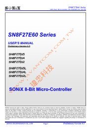
SONIX 松 翰 科 技 總 代 理 瑋 忠 科 技 WWW.AVANTCOM.COM.TW service@avantcom.com.twSN8F26E618-Bit Flash Micro-Controller with Embedded ICE and ISPSN8F26E61 SeriesUSER’S MANUALVersion 1.1SN8F26E61SN8F26E611SN8F26E61LSN8F26E611LSONiX 8-Bit Micro-ControllerSONIX reserves the right to make change without further notice to any products herein to improve reliability, function or design. SONIX does notassume any liability arising out of the application or use of any product or circuit described herein; neither does it convey any license under its patentrights nor the rights of others. SONIX products are not designed, intended, or authorized for us as components in systems intended, for surgicalimplant into the body, or other applications intended to support or sustain life, or for any other application in which the failure of the SONIX productcould create a situation where personal injury or death may occur. Should Buyer purchase or use SONIX products for any such unintended orunauthorized application. Buyer shall indemnify and hold SONIX and its officers, employees, subsidiaries, affiliates and distributors harmless againstall claims, cost, damages, and expenses, and reasonable attorney fees arising out of, directly or indirectly, any claim of personal injury or deathassociated with such unintended or unauthorized use even if such claim alleges that SONIX was negligent regarding the design or manufacture ofthe part.SONiX TECHNOLOGY CO., LTD Page 1 Version 1.1SONIX 松 翰 科 技 總 代 理 深 圳 奇 翰 電 子 WWW.AVANTCOM.COM.CN service@avantcom.com.cn
SONIX 松 翰 科 技 總 代 理 瑋 忠 科 技 WWW.AVANTCOM.COM.TW service@avantcom.com.twSN8F26E618-Bit Flash Micro-Controller with Embedded ICE and ISPAMENDENT HISTORYVersion Date DescriptionVER 0.1 Dec. 2010 First issue.VER 0.2 Jan. 2011 Add QFN and MSOP package type.VER 1.0 Apr. 2011 Remove 4M and 12M X’tal code option and add PDIP16/SOP16 package type.VER 1.1 Jun. 2011 Update electrical characteristic maximum rating.SONiX TECHNOLOGY CO., LTD Page 2 Version 1.1SONIX 松 翰 科 技 總 代 理 深 圳 奇 翰 電 子 WWW.AVANTCOM.COM.CN service@avantcom.com.cn
SONIX 松 翰 科 技 總 代 理 瑋 忠 科 技 WWW.AVANTCOM.COM.TW service@avantcom.com.twTable of ContentSN8F26E618-Bit Flash Micro-Controller with Embedded ICE and ISPAMENDENT HISTORY ................................................................................................................................ 211 PRODUCT OVERVIEW .............................................................................................................................. 81.1 FEATURES .............................................................................................................................................. 81.2 SYSTEM BLOCK DIAGRAM .............................................................................................................. 101.3 PIN ASSIGNMENT ............................................................................................................................... 111.4 PIN DESCRIPTIONS ............................................................................................................................. 121.5 PIN CIRCUIT DIAGRAMS ................................................................................................................... 1322 CENTRAL PROCESSOR UNIT (CPU) ................................................................................................... 152.1 PROGRAM MEMORY (FLASH ROM) ................................................................................................ 152.1.1 RESET VECTOR (0000H) ............................................................................................................. 162.1.2 INTERRUPT VECTOR (0008H~0012H) ....................................................................................... 172.1.3 LOOK-UP TABLE DESCRIPTION ............................................................................................... 192.1.4 JUMP TABLE DESCRIPTION ...................................................................................................... 212.1.5 CHECKSUM CALCULATION...................................................................................................... 232.2 DATA MEMORY (RAM) ...................................................................................................................... 242.2.1 SYSTEM REGISTER ..................................................................................................................... 242.2.1.1 SYSTEM REGISTER TABLE ................................................................................................ 242.2.1.2 SYSTEM REGISTER DESCRIPTION ................................................................................... 242.2.1.3 BIT DEFINITION of SYSTEM REGISTER ........................................................................... 252.2.2 ACCUMULATOR .......................................................................................................................... 272.2.3 PROGRAM FLAG .......................................................................................................................... 282.2.4 PROGRAM COUNTER.................................................................................................................. 292.2.5 H, L REGISTERS............................................................................................................................ 322.2.6 X REGISTERS ................................................................................................................................ 322.2.7 Y, Z REGISTERS............................................................................................................................ 332.2.8 R REGISTER .................................................................................................................................. 332.2.9 W REGISTERS ............................................................................................................................... 342.3 ADDRESSING MODE........................................................................................................................... 352.3.1 IMMEDIATE ADDRESSING MODE ........................................................................................... 352.3.2 DIRECTLY ADDRESSING MODE .............................................................................................. 352.3.3 INDIRECTLY ADDRESSING MODE .......................................................................................... 352.4 STACK OPERATION ............................................................................................................................ 362.4.1 OVERVIEW .................................................................................................................................... 362.4.2 STACK POINTER .......................................................................................................................... 362.4.3 STACK BUFFER ............................................................................................................................ 372.4.4 STACK OVERFLOW INDICATOR .............................................................................................. 372.4.5 STACK OPERATION EXAMPLE................................................................................................. 382.5 CODE OPTION TABLE ........................................................................................................................ 392.5.1 Fcpu Code Option ............................................................................................................................ 402.5.2 Reset_Pin code option ..................................................................................................................... 402.5.3 Security code option ........................................................................................................................ 402.5.4 Noise Filter code option .................................................................................................................. 4033 RESET .......................................................................................................................................................... 413.1 OVERVIEW ........................................................................................................................................... 413.2 POWER ON RESET ............................................................................................................................... 423.3 WATCHDOG RESET ............................................................................................................................ 423.4 BROWN OUT RESET ........................................................................................................................... 423.4.1 THE SYSTEM OPERATING VOLTAGE ..................................................................................... 43SONiX TECHNOLOGY CO., LTD Page 3 Version 1.1SONIX 松 翰 科 技 總 代 理 深 圳 奇 翰 電 子 WWW.AVANTCOM.COM.CN service@avantcom.com.cn
SONIX 松 翰 科 技 總 代 理 瑋 忠 科 技 WWW.AVANTCOM.COM.TW service@avantcom.com.twSN8F26E618-Bit Flash Micro-Controller with Embedded ICE and ISP3.4.2 LOW VOLTAGE DETECTOR (LVD) .......................................................................................... 433.4.3 BROWN OUT RESET IMPROVEMENT...................................................................................... 453.5 EXTERNAL RESET .............................................................................................................................. 463.6 EXTERNAL RESET CIRCUIT ............................................................................................................. 463.6.1 Simply RC Reset Circuit ................................................................................................................. 463.6.2 Diode & RC Reset Circuit ............................................................................................................... 473.6.3 Zener Diode Reset Circuit ............................................................................................................... 473.6.4 Voltage Bias Reset Circuit .............................................................................................................. 483.6.5 External Reset IC ............................................................................................................................. 4844 SYSTEM CLOCK ....................................................................................................................................... 494.1 OVERVIEW ........................................................................................................................................... 494.2 FCPU (INSTRUCTION CYCLE) ............................................................................................................ 494.3 NOISE FILTER ...................................................................................................................................... 494.4 SYSTEM HIGH-SPEED CLOCK .......................................................................................................... 494.4.1 HIGH_CLK CODE OPTION .......................................................................................................... 504.4.2 INTERNAL HIGH-SPEED OSCILLATOR RC TYPE (IHRC) .................................................... 504.4.3 EXTERNAL HIGH-SPEED OSCILLATOR .................................................................................. 504.4.4 EXTERNAL OSCILLATOR APPLICATION CIRCUIT .............................................................. 504.5 SYSTEM LOW-SPEED CLOCK ........................................................................................................... 514.6 OSCM REGISTER ................................................................................................................................. 514.7 SYSTEM CLOCK MEASUREMENT ................................................................................................... 524.8 SYSTEM CLOCK TIMING ................................................................................................................... 5255 SYSTEM OPERATION MODE ................................................................................................................ 555.1 OVERVIEW ........................................................................................................................................... 555.2 NORMAL MODE................................................................................................................................... 565.3 SLOW MODE......................................................................................................................................... 575.4 POWER DOWN MODE ......................................................................................................................... 575.5 GREEN MODE....................................................................................................................................... 585.6 OPERATING MODE CONTROL MACRO .......................................................................................... 595.7 WAKEUP ............................................................................................................................................... 605.7.1 OVERVIEW .................................................................................................................................... 605.7.2 WAKEUP TIME ............................................................................................................................. 605.7.3 P1W WAKEUP CONTROL REGISTER ....................................................................................... 6166 INTERRUPT ................................................................................................................................................ 626.1 OVERVIEW ........................................................................................................................................... 626.2 INTERRUPT OPERATION ........................................................................................................................... 626.3 INTEN INTERRUPT ENABLE REGISTER ......................................................................................... 636.4 INTRQ INTERRUPT REQUEST REGISTER ....................................................................................... 646.5 GIE GLOBAL INTERRUPT OPERATION .......................................................................................... 656.6 EXTERNAL INTERRUPT OPERATION (INT0) ................................................................................. 666.7 T0 INTERRUPT OPERATION .............................................................................................................. 676.8 TC0 INTERRUPT OPERATION ........................................................................................................... 686.9 TC1 INTERRUPT OPERATION ........................................................................................................... 696.10 TC2 INTERRUPT OPERATION ......................................................................................................... 706.11 T1 INTERRUPT OPERATION ............................................................................................................ 716.12 COMPARATOR INTERRUPT OPERATION (CMP0) ...................................................................... 726.13 SIO INTERRUPT OPERATION .......................................................................................................... 736.14 UART INTERRUPT OPERATION ..................................................................................................... 746.15 MULTI-INTERRUPT OPERATION ................................................................................................... 7577 I/O PORT ..................................................................................................................................................... 767.1 OVERVIEW ........................................................................................................................................... 767.2 I/O PORT MODE ................................................................................................................................... 77SONiX TECHNOLOGY CO., LTD Page 4 Version 1.1SONIX 松 翰 科 技 總 代 理 深 圳 奇 翰 電 子 WWW.AVANTCOM.COM.CN service@avantcom.com.cn
SONIX 松 翰 科 技 總 代 理 瑋 忠 科 技 WWW.AVANTCOM.COM.TW service@avantcom.com.twSN8F26E618-Bit Flash Micro-Controller with Embedded ICE and ISP7.3 I/O PULL UP REGISTER ...................................................................................................................... 787.4 I/O PORT DATA REGISTER ................................................................................................................ 7888 TIMERS ....................................................................................................................................................... 798.1 WATCHDOG TIMER ............................................................................................................................ 798.2 T0 8-BIT BASIC TIMER .............................................................................................................................. 818.2.1 OVERVIEW .................................................................................................................................... 818.2.2 T0 Timer Operation ......................................................................................................................... 828.2.3 T0M MODE REGISTER ................................................................................................................ 838.2.4 T0C COUNTING REGISTER ........................................................................................................ 838.2.5 T0 TIMER OPERATION EXPLAME ............................................................................................ 848.3 TC0 8-BIT TIMER/COUNTER ............................................................................................................. 858.3.1 OVERVIEW .................................................................................................................................... 858.3.2 TC0 TIMER OPERATION ............................................................................................................. 868.3.3 TC0M MODE REGISTER .............................................................................................................. 878.3.4 TC0C COUNTING REGISTER ..................................................................................................... 878.3.5 TC0R AUTO-RELOAD REGISTER .............................................................................................. 888.3.6 TC0D PWM DUTY REGISTER .................................................................................................... 888.3.7 TC0 EVENT COUNTER ................................................................................................................ 898.3.8 PULSE WIDTH MODULATION (PWM) ..................................................................................... 898.3.9 One Pulse PWM .............................................................................................................................. 908.3.10 TC0 TIMER OPERATION EXAMPLE ....................................................................................... 918.4 TC1 8-BIT TIMER/COUNTER ............................................................................................................. 938.4.1 OVERVIEW .................................................................................................................................... 938.4.2 TC1 TIMER OPERATION ............................................................................................................. 948.4.3 TC1M MODE REGISTER .............................................................................................................. 958.4.4 TC1C COUNTING REGISTER ..................................................................................................... 958.4.5 TC1R AUTO-RELOAD REGISTER .............................................................................................. 968.4.6 TC1D PWM DUTY REGISTER .................................................................................................... 968.4.7 TC1 EVENT COUNTER ................................................................................................................ 978.4.8 PULSE WIDTH MODULATION (PWM) ..................................................................................... 978.4.9 One Pulse PWM .............................................................................................................................. 988.4.10 TC1 TIMER OPERATION EXAMPLE ....................................................................................... 998.5 TC2 8-BIT TIMER/COUNTER ........................................................................................................... 1018.5.1 OVERVIEW .................................................................................................................................. 1018.5.2 TC2 TIMER OPERATION ........................................................................................................... 1028.5.3 TC2M MODE REGISTER ............................................................................................................ 1038.5.4 TC2C COUNTING REGISTER ................................................................................................... 1038.5.5 TC2R AUTO-RELOAD REGISTER ............................................................................................ 1048.5.6 TC2D PWM DUTY REGISTER .................................................................................................. 1048.5.7 TC2 EVENT COUNTER .............................................................................................................. 1058.5.8 PULSE WIDTH MODULATION (PWM) ................................................................................... 1058.5.9 One Pulse PWM ............................................................................................................................ 1068.5.10 TC2 TIMER OPERATION EXAMPLE ..................................................................................... 1078.6 T1 16-BIT TIMER WITH CAPTURE TIMER FUNCTION .............................................................................. 1098.6.1 OVERVIEW .................................................................................................................................. 1098.6.2 T1 TIMER OPERATION .............................................................................................................. 1108.6.3 T1M MODE REGISTER .............................................................................................................. 1118.6.4 T1CH, T1CL 16-bit COUNTING REGISTERS ........................................................................... 1118.6.5 T1 CPATURE TIMER .................................................................................................................. 1128.6.5.1 Capture Timer ......................................................................................................................... 1128.6.5.2 High Pulse Width Measurement ............................................................................................. 1148.6.5.3 Low Pulse Width Measurement ............................................................................................. 114SONiX TECHNOLOGY CO., LTD Page 5 Version 1.1SONIX 松 翰 科 技 總 代 理 深 圳 奇 翰 電 子 WWW.AVANTCOM.COM.CN service@avantcom.com.cn
SONIX 松 翰 科 技 總 代 理 瑋 忠 科 技 WWW.AVANTCOM.COM.TW service@avantcom.com.twSN8F26E618-Bit Flash Micro-Controller with Embedded ICE and ISP8.6.5.4 Input Cycle Measurement ....................................................................................................... 1148.6.6 CAPTURE TIMER CONTROL REGISTERS ............................................................................. 1158.6.7 T1 TIMER OPERATION EXAMPLE .......................................................................................... 11699 8-CHANNEL ANALOG COMPARAOTR ............................................................................................. 1189.1 OVERVIEW ......................................................................................................................................... 1189.2 COMPARATOR OPERATION ........................................................................................................... 1199.3 COMPARATOR CONTROL REGISTER ........................................................................................... 1219.4 COMPARATOR APPLICATION NOTICE ........................................................................................ 1221100 UNIVERSAL ASYNCHRONOUS RECEIVER/ TRANSMITTER (UART) .................................... 12310.1 OVERVIEW ....................................................................................................................................... 12310.2 UART OPERATION .......................................................................................................................... 12410.3 UART BAUD RATE .......................................................................................................................... 12510.4 UART TRANSFER FORMAT................................................................................................................... 12610.5 BREAK POCKET............................................................................................................................... 12610.6 ABNORMAL POCKET ..................................................................................................................... 12710.7 UART RECEIVER CONTROL REGISTER ...................................................................................... 12710.8 UART TRANSMITTER CONTROL REGISTER ............................................................................. 12810.9 UART DATA BUFFER ...................................................................................................................... 12810.10 UART OPERATION EXAMLPE .................................................................................................... 1291111 SERIAL INPUT/OUTPUT TRANSCEIVER (SIO) ............................................................................ 13211.1 OVERVIEW ....................................................................................................................................... 13211.2 SIO OPERATION............................................................................................................................... 13211.3 SIOM MODE REGISTER .................................................................................................................. 13511.4 SIOB DATA BUFFER ....................................................................................................................... 13611.5 SIOR REGISTER DESCRIPTION ..................................................................................................... 1371122 IN SYSTEM PROGRAM FLASH ROM .............................................................................................. 13812.1 OVERVIEW ....................................................................................................................................... 13812.2 ISP FLASH ROM ERASE OPERATION .......................................................................................... 13912.3 ISP FLASH ROM PROGRAM OPERATION ................................................................................... 14012.4 ISP PROGRAM/ERASE CONTROL REGISTER ............................................................................. 14312.5 ISP ROM ADDRESS REGISTER ...................................................................................................... 14312.6 ISP RAM ADDRESS REGISTER ...................................................................................................... 14312.7 ISP ROM PROGRAMMING LENGTH REGISTER ......................................................................... 1441133 INSTRUCTION TABLE ........................................................................................................................ 1451144 ELECTRICAL CHARACTERISTIC ................................................................................................... 14714.1 ABSOLUTE MAXIMUM RATING .................................................................................................. 14714.2 ELECTRICAL CHARACTERISTIC ................................................................................................. 14714.3 CHARACTERISTIC GRAPHS .......................................................................................................... 1491155 DEVELOPMENT TOOL ....................................................................................................................... 15015.1 SMART DEVELOPMENT ADAPTER ........................................................................................................ 15015.2 SN8F26E61 STARTER-KIT ................................................................................................................... 15115.3 EMULATOR/DEBUGGER INSTALLATION ........................................................................................... 15215.4 PROGRAMMER INSTALLATION ......................................................................................................... 1531166 ROM PROGRAMMING PIN ................................................................................................................ 15416.1 MP-III WRITER TRANSITION BOARD SOCKET PIN ASSIGNMENT ....................................... 15416.2 MP-III WRITER PROGRAMMING PIN MAPPING ........................................................................ 1551177 MARKING DEFINITION ...................................................................................................................... 15717.1 INTRODUCTION .............................................................................................................................. 15717.2 MARKING INDETIFICATION SYSTEM ........................................................................................ 15717.3 MARKING EXAMPLE ...................................................................................................................... 15817.4 DATECODE SYSTEM ...................................................................................................................... 1591188 PACKAGE INFORMATION ................................................................................................................ 160SONiX TECHNOLOGY CO., LTD Page 6 Version 1.1SONIX 松 翰 科 技 總 代 理 深 圳 奇 翰 電 子 WWW.AVANTCOM.COM.CN service@avantcom.com.cn
SONIX 松 翰 科 技 總 代 理 瑋 忠 科 技 WWW.AVANTCOM.COM.TW service@avantcom.com.twSN8F26E618-Bit Flash Micro-Controller with Embedded ICE and ISP18.1 P-DIP 16 PIN ...................................................................................................................................... 16018.2 SOP 16 PIN ......................................................................................................................................... 16118.3 SSOP 16 PIN ....................................................................................................................................... 16218.4 QFN 3X3 16 PIN ................................................................................................................................. 16318.5 P-DIP 14 PIN ...................................................................................................................................... 16418.6 SOP 14 PIN ......................................................................................................................................... 16518.7 MSOP 10 PIN ..................................................................................................................................... 166SONiX TECHNOLOGY CO., LTD Page 7 Version 1.1SONIX 松 翰 科 技 總 代 理 深 圳 奇 翰 電 子 WWW.AVANTCOM.COM.CN service@avantcom.com.cn
SONIX 松 翰 科 技 總 代 理 瑋 忠 科 技 WWW.AVANTCOM.COM.TW service@avantcom.com.twSN8F26E618-Bit Flash Micro-Controller with Embedded ICE and ISP1 PRODUCT OVERVIEWSN8F26E61 series 8-bit micro-controller is a low pin count series production applied advanced semiconductortechnology to implement flash ROM architecture. Under flash ROM platform, SN8F26E61 builds inin-system-programming (ISP) function extending to EEPROM emulation and Embedded ICE (EICE) function. It offershigh performance 8-ch Comparator, T1 capture timer, 3-set individual programmable PWMs, 2-type serial interfacesand flexible operating modes. Powerful functionality, high reliability and low power consumption can apply to AC powerapplication and battery level application easily.1.1 FEATURES Memory configuration Four 8-bit timer. (T0, TC0, TC1, TC2).Flash ROM size: 2K * 16 bits. Including EEPOMT0: Basic timer.Emulation. (Including in system programming)TC0: Timer/counter/PWM0.RAM size: 128 * 8 bits.TC1: Timer/counter/PWM1. 8 levels stack buffer.TC2: Timer/counter/PWM2 11 interrupt sources 3 channel duty/cycle programmable PWM to10 internal interrupts: T0, TC0, TC1, TC2, T1, SIO Generate PWM, Buzzer and IR carrier signals.CM0, UTX, URX, WAKE(PWM0~2).1 external interrupt: INT0 One 16-bit timer (T1) with capture timer function. Multi-interrupt vector structure 3P/8N multi-channel comparator.Each of interrupt sources has a unique interrupt vector. Serial Interface: SIO, UART I/O pin configuration Build in Embedded ICE function.Bi-directional: P0, P1 Four system clocksWakeup: P0, P1 level change.External high clock: RC type up to 10MHzPull-up resisters: P0, P1External high clock: Crystal type up to 32KHzExternal interrupt: P0.0Internal high clock: RC type 16MHzComparator input pin: P1Internal low clock: RC type 16KHz Fcpu (Instruction cycle) Four operating modesFcpu = Fhosc/1, Fhosc/2, Fhosc/4, Fhosc/8,Normal mode: Both high and low clock activeFhosc/16, Fhosc/32, Fhosc/64, Fhosc/128Slow mode: Low clock only On chip watchdog timer and clock sourceSleep mode: Both high and low clock stop 1.8V/2.4V/3.3V 3-level LVD with trim.Green mode: Periodical wakeup by timer Powerful instructions Package (Chip form support)Instruction’s length is one word.PDIP 16 pinMost of instructions are one cycle only.SOP 16 pinAll ROM area JMP/CALL instruction.SSOP 16 pinAll ROM area lookup table function (MOVC).QFN 16 pinPDIP 14 pinSOP 14 pinMSOP 10 pinSONiX TECHNOLOGY CO., LTD Page 8 Version 1.1SONIX 松 翰 科 技 總 代 理 深 圳 奇 翰 電 子 WWW.AVANTCOM.COM.CN service@avantcom.com.cn
SONIX 松 翰 科 技 總 代 理 瑋 忠 科 技 WWW.AVANTCOM.COM.TW service@avantcom.com.twSN8F26E618-Bit Flash Micro-Controller with Embedded ICE and ISPSN8P26E61series micro-controller includes two types for different power types.For AC power type (alternating current power source) and DC high voltage power(≦5.5V), the power pin has VDD andVDDL. VDD pin is connect to DC power source from DC-DC inverter or regulator and connects a 0.1uF capacitor toVSS pin (ground). VDDL is internal power terminal, not connect with power source, and only connects a 0.1uFcapacitor to VSS pin (ground). This pin assignment has high power noise immunity, but the static current is larger. Theapplication field is household, motor control…VDDVDDLVSS(1.8V~5.5V)0.1uF0.1uFRegulator+-RectificationLAC PowerSourceNVDDVDDLVSS0.1uF+DC Power0.1uFSource(1.8V~5.5V)-SN8F26E61Series <strong>MCU</strong>SN8F26E61Series <strong>MCU</strong>For DC power type (battery power source), the power pin is VDD. VDD pin is connect to DC power source from batteryand connects a 0.1uF capacitor to VSS pin (ground). This pin assignment has low power noise immunity, but the staticcurrent is very low. The application field is portable application…VDD(1.8V~3.3V)Regulator+VDD+VSS0.1uFDC PowerSource(>3.3V)-VSS0.1uFDC PowerSource(1.8V~3.3V)-SN8F26E61LSeries <strong>MCU</strong>SN8F26E61LSeries <strong>MCU</strong> Features Selection TableSN8F26E61 SeriesCHIP ROM RAM Stack Timer I/O PWM CMP SIO UART MSP Ext.INTISP/EmbeddedICEOperatingVoltagePackageSN8F26E61 2K*16 128 8 8-bit*4 13 3-ch 8-ch V V - 1 V 1.8V~5.5VPDIP16SOP16SSOP16QFN16SN8F26E611 2K*16 128 8 8-bit*4 11 3-ch 8-ch V V - 1 V 1.8V~5.5VPDIP14SOP14SN8F26E611 2K*16 128 8 8-bit*4 7 3-ch 6-ch V V - 1 V 1.8V~5.5V MSOP10SN8F26E61L SeriesCHIP ROM RAM Stack Timer I/O PWM CMP SIO UART MSP Ext.INTISP/EmbeddedICEOperatingVoltagePackageSN8F26E61L 2K*16 128 8 8-bit*4 13 3-ch 8-ch V V - 1 V 1.8V~3.3VPDIP16SOP16SSOP16QFN16SN8F26E611L 2K*16 128 8 8-bit*4 11 3-ch 8-ch V V - 1 V 1.8V~3.3VPDIP14SOP14SN8F26E611L 2K*16 128 8 8-bit*4 7 3-ch 6-ch V V - 1 V 1.8V~3.3V MSOP10SONiX TECHNOLOGY CO., LTD Page 9 Version 1.1SONIX 松 翰 科 技 總 代 理 深 圳 奇 翰 電 子 WWW.AVANTCOM.COM.CN service@avantcom.com.cn
SONIX 松 翰 科 技 總 代 理 瑋 忠 科 技 WWW.AVANTCOM.COM.TW service@avantcom.com.twSN8F26E618-Bit Flash Micro-Controller with Embedded ICE and ISP1.2 SYSTEM BLOCK DIAGRAMPCINTERNAL HIGHRC 16MHz3-Level LVD(Low Voltage Detector)IRFLAGSFLASHROMEXTERNALHIGH OSC.INTERNALLOW RCWATCHDOG TIMEREmbedded ICESystemEIDA, EICKTIMING GENERATOR8-ch ComparatorCN0~CN7ALURAMUARTUTX,URXSIOSCK,SDI,SDO,SCSACCSYSTEM REGISTERSPWM0PWM0INTERRUPTCONTROLTIMER & COUNTERPWM1PWM1PWM2PWM2P0P1SONiX TECHNOLOGY CO., LTD Page 10 Version 1.1SONIX 松 翰 科 技 總 代 理 深 圳 奇 翰 電 子 WWW.AVANTCOM.COM.CN service@avantcom.com.cn
SONIX 松 翰 科 技 總 代 理 瑋 忠 科 技 WWW.AVANTCOM.COM.TW service@avantcom.com.twSN8F26E618-Bit Flash Micro-Controller with Embedded ICE and ISP1.3 PIN ASSIGNMENT• SN8F26E61P (AC field, DIP 16 Pin):• SN8F26E61S (AC field, SOP 16 Pin):• SN8F26E61X (AC field, SSOP 16 Pin):VSS 1 U 16 VDDLP0.0/XIN/INT0/TC0 2 15 VDDP0.1/XOUT/TC1 3 14 P1.0/CN0/CP0/UTX/SCKP0.2/RST/TC2 4 13 P1.1/CN1/CP1/URX/SDIP0.3 5 12 P1.2/CN2/SDOP0.4 6 11 P1.3/CN3/SCSP1.7/CN7/PWM0/CM0O/T1 7 10 P1.4/CN4P1.6/CN6/PWM1/EIDA 8 9 P1.5/CN5/PWM2/EICK• SN8F26E61LP (DC field, DIP 16 Pin):• SN8F26E61LS (DC field, SOP 16 Pin):• SN8F26E61LX (DC field, SSOP 16 Pin):VSS 1 U 16 VDDP0.0/XIN/INT0/TC0 2 15 VDDP0.1/XOUT/TC1 3 14 P1.0/CN0/CP0/UTX/SCKP0.2/RST/TC2 4 13 P1.1/CN1/CP1/URX/SDIP0.3 5 12 P1.2/CN2/SDOP0.4 6 11 P1.3/CN3/SCSP1.7/CN7/PWM0/CM0O/T1 7 10 P1.4/CN4P1.6/CN6/PWM1/EIDA 8 9 P1.5/CN5/PWM2/EICK• SN8F26E61J (AC field, QFN 3x3 16 Pin): • SN8F26E61LJ (DC field, QFN 3x3 16 Pin):P0.0/XIN/INT0/TC0VSSVDDLVDD16 15 14 13P0.1/XOUT/TC1 1 O12 P1.0/CN0/CP0/UTX/SCKP0.2/RST/TC2 211 P1.1/CN1/CP1/URX/SDIP0.3 3 10 P1.2/CN2/SDOP0.4 4 9 P1.3/CN3/SCS5 6 7 8P0.0/XIN/INT0/TC0VSSVDDVDD16 15 14 13P0.1/XOUT/TC1 1 O12 P1.0/CN0/CP0/UTX/SCKP0.2/RST/TC2 211 P1.1/CN1/CP1/URX/SDIP0.3 3 10 P1.2/CN2/SDOP0.4 4 9 P1.3/CN3/SCS5 6 7 8P1.4/CN4P1.5/CN5/PWM2/EICKP1.6/CN6/PWM1/EIDAP1.7/CN7/PWM0/CM0O/T1P1.4/CN4P1.5/CN5/PWM2/EICKP1.6/CN6/PWM1/EIDAP1.7/CN7/PWM0/CM0O/T1• SN8F26E611P (AC field, DIP 14 Pin):• SN8F26E611S (AC field, SOP 14 Pin):VSS 1 U 14 VDDLP0.0/XIN/INT0/TC0 2 13 VDDP0.1/XOUT/TC1 3 12 P1.0/CN0/CP0/UTX/SCKP0.2/RST/TC2 4 11 P1.1/CN1/CP1/URX/SDIP1.7/CN7/PWM0/CM0O/T1 5 10 P1.2/CN2/SDOP1.6/CN6/PWM1/EIDA 6 9 P1.3/CN3/SCSP1.5/CN5/PWM2/EICK 7 8 P1.4/CN4• SN8F26E611LP (DC field, DIP 14 Pin):• SN8F26E611LS (DC field, SOP 14 Pin):VSS 1 U 14 VDDP0.0/XIN/INT0/TC0 2 13 VDDP0.1/XOUT/TC1 3 12 P1.0/CN0/CP0/UTX/SCKP0.2/RST/TC2 4 11 P1.1/CN1/CP1/URX/SDIP1.7/CN7/PWM0/CM0O/T1 5 10 P1.2/CN2/SDOP1.6/CN6/PWM1/EIDA 6 9 P1.3/CN3/SCSP1.5/CN5/PWM2/EICK 7 8 P1.4/CN4• SN8F26E611A (AC field, MSOP 10 Pin): • SN8F26E611LA (DC field, MSOP 10 Pin):P0.0/XIN/INT0/TC0 1 U 10 VSSP0.0/XIN/INT0/TC0 1 U 10 VSSP1.7/CN7/PWM0/CM0O/T1 2 9 VDDLP1.7/CN7/PWM0/CM0O/T1 2 9 VDDP1.6/CN6/PWM1/EIDA 3 8 VDDP1.6/CN6/PWM1/EIDA 3 8 VDDP1.5/CN5/PWM2/EICK 4 7 P1.0/CN0/CP0/UTX/SCK P1.5/CN5/PWM2/EICK 4 7 P1.0/CN0/CP0/UTX/SCKP1.2/CN2/SDO 5 6 P1.1/CN1/CP1/URX/SDIP1.2/CN2/SDO 5 6 P1.1/CN1/CP1/URX/SDISONiX TECHNOLOGY CO., LTD Page 11 Version 1.1SONIX 松 翰 科 技 總 代 理 深 圳 奇 翰 電 子 WWW.AVANTCOM.COM.CN service@avantcom.com.cn
SONIX 松 翰 科 技 總 代 理 瑋 忠 科 技 WWW.AVANTCOM.COM.TW service@avantcom.com.tw1.4 PIN DESCRIPTIONSSN8F26E618-Bit Flash Micro-Controller with Embedded ICE and ISPPIN NAME TYPE DESCRIPTIONVDD, VSS P Power supply input pins for digital and analog circuit.VDDL P Low voltage power pin. Connect 0.1uF capacitor to Vss.P0.2/RST/TC2 I/ORST: System external reset input pin. Schmitt trigger structure, active “low”, normal stay to “high”.P0.2: Bi-direction pin. Schmitt trigger structure as input mode. Built-in pull-up resisters. Level changewake-up.P0.0/XIN/INT0/TC0P0.1/XOUT/TC1I/OI/OP0.3 I/OP0.4 I/OP1.0/CN0/CP0/UTX/SCKP1.1/CN1/CP1/URX/SDIP1.2/CN2/SDOP1.3/CN3/SCSP1.4/CN4P1.5/CN5/PWM2/EICKP1.6/CN6/PWM1/EIDAP1.7/CN7/PWM0/CM0O/T1I/OI/OI/OI/OI/OI/OI/OI/OTC2: TC2 event counter input pin.XIN: Oscillator input pin while external oscillator enable (crystal and RC).P0.0: Bi-direction pin. Schmitt trigger structure as input mode. Built-in pull-up resisters. Level changewake-up.INT0: External interrupt 0 input pin.TC0: TC0 event counter input pin.XOUT: Oscillator output pin while external crystal enable.P0.1: Bi-direction pin. Schmitt trigger structure as input mode. Built-in pull-up resisters. Level changewake-up.TC1: TC1 event counter input pin.P0.3: Bi-direction pin. Schmitt trigger structure as input mode. Built-in pull-up resisters. Level changewake-up.P0.4: Bi-direction pin. Schmitt trigger structure as input mode. Built-in pull-up resisters. Level changewake-up.P1.0: Bi-direction pin. Schmitt trigger structure as input mode. Built-in pull-up resisters. Level changewake-up.CN0: Channel 0 of comparator negative input pin.CP0: Channel 0 of comparator positive input pin.UTX: UART transmit output pin.SCK: SIO clock pin.P1.1: Bi-direction pin. Schmitt trigger structure as input mode. Built-in pull-up resisters. Level changewake-up.CN1: Channel 1 of comparator negative input pin.CP1: Channel 1 of comparator positive input pin.URX: UART receive input pin.SDI: SIO data input pin.P1.2: Bi-direction pin. Schmitt trigger structure as input mode. Built-in pull-up resisters. Level changewake-up.CN2: Channel 2 of comparator negative input pin.SDO: SIO data output pin.P1.3: Bi-direction pin. Schmitt trigger structure as input mode. Built-in pull-up resisters. Level changewake-up.CN3: Channel 3 of comparator negative input pin.SCS: SIO bus control pin.P1.4: Bi-direction pin. Schmitt trigger structure as input mode. Built-in pull-up resisters. Level changewake-up.CN4: Channel 4 of comparator negative input pin.P1.5: Bi-direction pin. Schmitt trigger structure as input mode. Built-in pull-up resisters. Level changewake-up.CN5: Channel 5 of comparator negative input pin.PWM2: PWM 2 output pin.EICK: Embedded ICE clock pin.P1.6: Bi-direction pin. Schmitt trigger structure as input mode. Built-in pull-up resisters. Level changewake-up.CN6: Channel 6 of comparator negative input pin.PWM1: PWM 1 output pin.EIDA: Embedded ICE data pin.P1.7: Bi-direction pin. Schmitt trigger structure as input mode. Built-in pull-up resisters. Level changewake-up. Programmable open-drain structure.CN7: Channel 7 of comparator negative input pin.PWM0: PWM 0 output pin.CM0O: The output pin of comparator.T1: T1 event counter input pin.SONiX TECHNOLOGY CO., LTD Page 12 Version 1.1SONIX 松 翰 科 技 總 代 理 深 圳 奇 翰 電 子 WWW.AVANTCOM.COM.CN service@avantcom.com.cn
SONIX 松 翰 科 技 總 代 理 瑋 忠 科 技 WWW.AVANTCOM.COM.TW service@avantcom.com.twSN8F26E618-Bit Flash Micro-Controller with Embedded ICE and ISP1.5 PIN CIRCUIT DIAGRAMS• Normal Bi-direction I/O Pin.Pull-UpResistorPnMPnURPinI/O Input BusPnMOutputLatchI/O Output Bus• Bi-direction I/O Pin Shared with Specific Digital Input Function, e.g. INT0, Event counter, SIO, UART.Pull-UpResistorSpecific InputFunction Control BitPnMPnURSpecific Input BusPinIO Input BusPnMOutputLatchOutput Bus*. Specific OutputFunction Control Bit*. Some specific functions switch I/O direction directly, not through PnM register.• Bi-direction I/O Pin Shared with Specific Digital Output Function, e.g. PWM, SIO, UART.Pull-UpResistorPnMPnURPinIO Input BusPnM*. Specific OutputFunction Control BitOutputLatchSpecific OutputFunction Control BitOutput BusSpecific Output Bus*. Some specific functions switch I/O direction directly, not through PnM register.• Bi-direction I/O Pin Shared with Specific Analog Input Function, e.g. XIN, CMP.Pull-UpResistor*. Specific AnalogFunction Control BitPnMPnURPinI/O Input BusPnMOutputLatchI/O Output BusAnalog IP InputTerminal*. Some specific functions switch I/O direction directly, not through PnM register.SONiX TECHNOLOGY CO., LTD Page 13 Version 1.1SONIX 松 翰 科 技 總 代 理 深 圳 奇 翰 電 子 WWW.AVANTCOM.COM.CN service@avantcom.com.cn
SONIX 松 翰 科 技 總 代 理 瑋 忠 科 技 WWW.AVANTCOM.COM.TW service@avantcom.com.twSN8F26E618-Bit Flash Micro-Controller with Embedded ICE and ISP• Bi-direction I/O Pin Shared with Specific Analog Output Function, e.g. XOUT…Pull-UpResistor*. Specific AnalogFunction Control BitPnMPnURPinPnMI/O Input BusOutputLatchI/O Output BusAnalog IP OutputTerminal*. Some specific functions switch I/O direction directly, not through PnM register.SONiX TECHNOLOGY CO., LTD Page 14 Version 1.1SONIX 松 翰 科 技 總 代 理 深 圳 奇 翰 電 子 WWW.AVANTCOM.COM.CN service@avantcom.com.cn
SONIX 松 翰 科 技 總 代 理 瑋 忠 科 技 WWW.AVANTCOM.COM.TW service@avantcom.com.twSN8F26E618-Bit Flash Micro-Controller with Embedded ICE and ISP2 CENTRAL PROCESSOR UNIT (CPU)2.1 PROGRAM MEMORY (FLASH ROM)2K words FLASH ROMAddress ROM Comment0000H Reset vector Reset vector0001HUser program.0007H0008HGeneral purpose areaWAKE Interrupt vector Interrupt vector0009H INT0 Interrupt vector000AH T0 Interrupt vector000BH TC0 Interrupt vector000CH TC1 Interrupt vector000DH TC2 Interrupt vector000EH T1 Interrupt vector000FH CM0 Interrupt vector0010H SIO Interrupt vector0011H UART RX Interrupt vector0012H UART TX Interrupt vector0013HUser program.. General purpose area.07F7HEnd of user program07F8H07F9H.07FDHReserved07FEH07FFHThe ROM includes Reset vector, Interrupt vector, General purpose area and Reserved area. The Reset vector isprogram beginning address. The Interrupt vector is the head of interrupt service routine when any interrupt occurring.The General purpose area is main program area including main loop, sub-routines and data table.• 0x0000 Reset Vector: Program counter points to 0x0000 after any reset events (power on reset, reset pinreset, watchdog reset, LVD reset…).• 0x0001~0x0007: General purpose area to process system reset operation.• 0x0008~0x0012: Multi interrupt vector area. Each of interrupt events has a unique interrupt vector.• 0x0013~0x077F: General purpose area for user program and ISP (EEPROM function).• 0x0780~0x07F7: General purpose area for user program. Do not execute ISP.• 0x07F8~0x07FF: Reserved area. Do not execute ISP.• ROM security rule is even address ROM data protected and outputs 0x0000.SONiX TECHNOLOGY CO., LTD Page 15 Version 1.1SONIX 松 翰 科 技 總 代 理 深 圳 奇 翰 電 子 WWW.AVANTCOM.COM.CN service@avantcom.com.cn
SONIX 松 翰 科 技 總 代 理 瑋 忠 科 技 WWW.AVANTCOM.COM.TW service@avantcom.com.twSN8F26E618-Bit Flash Micro-Controller with Embedded ICE and ISP2.1.1 RESET VECTOR (0000H)A one-word vector address area is used to execute system reset.Power On Reset (POR=1).Watchdog Reset (WDT=1).External Reset (RST=1)After power on reset, external reset or watchdog timer overflow reset, then the chip will restart the program fromaddress 0000h and all system registers will be set as default values. It is easy to know reset status from POR, WDT,and RST flags of PFLAG register. The following example shows the way to define the reset vector in the programmemory.‣ Example: Defining Reset VectorORG 0 ; 0000HJMP START ; Jump to user program address.…START:ORG……13H; 0012H, The head of user program.; User programENDP; End of programNote: The head of user program should skip interrupt vector area to avoid program execution error.SONiX TECHNOLOGY CO., LTD Page 16 Version 1.1SONIX 松 翰 科 技 總 代 理 深 圳 奇 翰 電 子 WWW.AVANTCOM.COM.CN service@avantcom.com.cn
SONIX 松 翰 科 技 總 代 理 瑋 忠 科 技 WWW.AVANTCOM.COM.TW service@avantcom.com.twSN8F26E618-Bit Flash Micro-Controller with Embedded ICE and ISP2.1.2 INTERRUPT VECTOR (0008H~0012H)A 11-word vector address area is used to execute interrupt request. If any interrupt service executes, the programcounter (PC) value is stored in stack buffer and jump to 0008h~0012h of program memory to execute the vectoredinterrupt. This interrupt is multi-vector and each of interrupts points to unique vector. Users have to define the interruptvector. The following example shows the way to define the interrupt vector in the program memory.Note: The “PUSH” and “POP” operations aren’t through instruction (PUSH, POP) and can executed saveand load ACC and working registers (0x80~0x8F) by hardware automatically.ROMPriority0008H WAKE Interrupt vector 10009H INT0 Interrupt vector 2000AH T0 Interrupt vector 3000BH TC0 Interrupt vector 4000CH TC1 Interrupt vector 5000DH TC2 Interrupt vector 6000EH T1 Interrupt vector 7000FH CM0 Interrupt vector 80010H SIO Interrupt vector 90011H UART RX Interrupt vector 100012H UART TX Interrupt vector 11When one interrupt request occurs, and the program counter points to the correlative vector to execute interruptservice routine. If WAKE interrupt occurs, the program counter points to ORG 8. If INT0 interrupt occurs, the programcounter points to ORG 9. In normal condition, several interrupt requests happen at the same time. So the priority ofinterrupt sources is very important, or the system doesn’t know which interrupt is processed first. The interrupt priorityis follow vector sequence. ORG 8 is priority 1. ORG 9 is priority 2. In the case, the interrupt processing priority is asfollowing.If WAKE, T0, TC2, CM0 and SIO interrupt requests happen at the same time, the system processing interruptsequence is WAKE, T0, TC2, CM0, and then SIO. The system processes WAKE interrupt service routine first, and thenprocesses T0 interrupt routine…Until finishing processing all interrupt requests.‣ Example:Interrupt Request Occurrence Sequence: (2~8 interrupt requests occur during WAKE interrupt service routineexecution.)1 2 3 4 5 6 7 8WAKE CM0 TC1 T0 SIO INT0 TC2 UART RXInterrupt Processing Sequence:1 2 3 4 5 6 7 8WAKE INT0 T0 TC1 TC2 CM0 SIO UART RXSONiX TECHNOLOGY CO., LTD Page 17 Version 1.1SONIX 松 翰 科 技 總 代 理 深 圳 奇 翰 電 子 WWW.AVANTCOM.COM.CN service@avantcom.com.cn
SONIX 松 翰 科 技 總 代 理 瑋 忠 科 技 WWW.AVANTCOM.COM.TW service@avantcom.com.twSN8F26E618-Bit Flash Micro-Controller with Embedded ICE and ISP‣ Example: Defining Interrupt Vector. The interrupt service routine is following user program..CODEORG 0 ; 0000HJMP START ; Jump to user program address.…ORG 8 ; Interrupt vector, 0008H.JMP ISR_WAKE ; Jump to interrupt service routine address.JMP ISR_INT0JMP ISR_T0JMP ISR_TC0JMP ISR_TC1JMP ISR_TC2JMP ISR_T1JMP ISR_CM0JMP ISR_SIOJMP ISR_UART_RXJMP ISR_UART_TXORG 13HSTART:; 0013H, The head of user program.…; User program.……JMP START ; End of user program.…ISR_WAKE:; The head of interrupt service routine.; Save ACC and 0x80~0x8F register to buffers.…; Load ACC and 0x80~0x8F register from buffers.RETI; End of interrupt service routine.ISR_INT0: ;; Save ACC and 0x80~0x8F register to buffers.…; Load ACC and 0x80~0x8F register from buffers.RETI; End of interrupt service routine.……………ISR_UART_TX: ;; Save ACC and 0x80~0x8F register to buffers.…; Load ACC and 0x80~0x8F register from buffers.RETI; End of interrupt service routine.ENDP; End of program.Note: It is easy to understand the rules of SONIX program from demo programs given above. Thesepoints are as following:1. The address 0000H is a “JMP” instruction to make the program starts from the beginning.2. The address 0008H~0012H is interrupt vector.3. User’s program is a loop routine for main purpose application.SONiX TECHNOLOGY CO., LTD Page 18 Version 1.1SONIX 松 翰 科 技 總 代 理 深 圳 奇 翰 電 子 WWW.AVANTCOM.COM.CN service@avantcom.com.cn
SONIX 松 翰 科 技 總 代 理 瑋 忠 科 技 WWW.AVANTCOM.COM.TW service@avantcom.com.twSN8F26E618-Bit Flash Micro-Controller with Embedded ICE and ISP2.1.3 LOOK-UP TABLE DESCRIPTIONIn the ROM’s data lookup function, Y register is pointed to middle byte address (bit 8~bit 15) and Z register is pointedto low byte address (bit 0~bit 7) of ROM. After MOVC instruction executed, the low-byte data will be stored in ACC andhigh-byte data stored in R register.‣ Example: To look up the ROM data located “TABLE1”.B0MOV Y, #TABLE1$M ; To set lookup table1’s middle addressB0MOV Z, #TABLE1$L ; To set lookup table1’s low address.MOVC; To lookup data, R = 00H, ACC = 35H; Increment the index address for next address.INCMS Z ; Z+1JMP @F ; Z is not overflow.INCMS Y ; Z overflow (FFH 00), Y=Y+1NOP ;;@@: MOVC ; To lookup data, R = 51H, ACC = 05H.… ;TABLE1: DW 0035H ; To define a word (16 bits) data.DW 5105HDW 2012H…Note: The Y register will not increase automatically when Z register crosses boundary from 0xFF to0x00. Therefore, user must be take care such situation to avoid look-up table errors. If Z register isoverflow, Y register must be added one. The following INC_YZ macro shows a simple method to processY and Z registers automatically.‣ Example: INC_YZ macro.INC_YZ@@:MACROINCMS Z ; Z+1JMP @F ; Not overflowINCMS Y ; Y+1NOP; Not overflowENDMSONiX TECHNOLOGY CO., LTD Page 19 Version 1.1SONIX 松 翰 科 技 總 代 理 深 圳 奇 翰 電 子 WWW.AVANTCOM.COM.CN service@avantcom.com.cn
SONIX 松 翰 科 技 總 代 理 瑋 忠 科 技 WWW.AVANTCOM.COM.TW service@avantcom.com.twSN8F26E618-Bit Flash Micro-Controller with Embedded ICE and ISP‣ Example: Modify above example by “INC_YZ” macro.B0MOV Y, #TABLE1$M ; To set lookup table1’s middle addressB0MOV Z, #TABLE1$L ; To set lookup table1’s low address.MOVC; To lookup data, R = 00H, ACC = 35HINC_YZ; Increment the index address for next address.;@@: MOVC ; To lookup data, R = 51H, ACC = 05H.… ;TABLE1: DW 0035H ; To define a word (16 bits) data.DW 5105HDW 2012H…The other example of look-up table is to add Y or Z index register by accumulator. Please be careful if “carry” happen.‣ Example: Increase Y and Z register by B0ADD/ADD instruction.B0MOV Y, #TABLE1$M ; To set lookup table’s middle address.B0MOV Z, #TABLE1$L ; To set lookup table’s low address.B0MOV A, BUF ; Z = Z + BUF.B0ADD Z, AB0BTS1 FC ; Check the carry flag.JMP GETDATA ; FC = 0INCMS Y ; FC = 1. Y+1.NOPGETDATA: ;MOVC…; To lookup data. If BUF = 0, data is 0x0035; If BUF = 1, data is 0x5105; If BUF = 2, data is 0x2012TABLE1: DW 0035H ; To define a word (16 bits) data.DW 5105HDW 2012H…SONiX TECHNOLOGY CO., LTD Page 20 Version 1.1SONIX 松 翰 科 技 總 代 理 深 圳 奇 翰 電 子 WWW.AVANTCOM.COM.CN service@avantcom.com.cn
SONIX 松 翰 科 技 總 代 理 瑋 忠 科 技 WWW.AVANTCOM.COM.TW service@avantcom.com.twSN8F26E618-Bit Flash Micro-Controller with Embedded ICE and ISP2.1.4 JUMP TABLE DESCRIPTIONThe jump table operation is one of multi-address jumping function. Add low-byte program counter (PCL) and ACCvalue to get one new PCL. If PCL is overflow after PCL+ACC, PCH adds one automatically. The new program counter(PC) points to a series jump instructions as a listing table. It is easy to make a multi-jump program depends on thevalue of the accumulator (A).Note: PCH only support PC up counting result and doesn’t support PC down counting. When PCL iscarry after PCL+ACC, PCH adds one automatically. If PCL borrow after PCL–ACC, PCH keeps value andnot change.‣ Example: Jump table.ORG 0X0100 ; The jump table is from the head of the ROM boundaryB0ADD PCL, A ; PCL = PCL + ACC, PCH + 1 when PCL overflow occurs.JMP A0POINT ; ACC = 0, jump to A0POINTJMP A1POINT ; ACC = 1, jump to A1POINTJMP A2POINT ; ACC = 2, jump to A2POINTJMP A3POINT ; ACC = 3, jump to A3POINTSONIX provides a macro for safe jump table function. This macro will check the ROM boundary and move the jumptable to the right position automatically. The side effect of this macro maybe wastes some ROM size.‣ Example: If “jump table” crosses over ROM boundary will cause errors.@JMP_A MACRO VALIF(($+1) !& 0XFF00) !!= (($+(VAL)) !& 0XFF00)JMP ($ | 0XFF)ORG ($ | 0XFF)ENDIFB0ADD PCL, AENDMNote: “VAL” is the number of the jump table listing number.‣ Example: “@JMP_A” application in SONIX macro file called “MACRO3.H”.B0MOV A, BUF0 ; “BUF0” is from 0 to 4.@JMP_A 5 ; The number of the jump table listing is five.JMP A0POINT ; ACC = 0, jump to A0POINTJMP A1POINT ; ACC = 1, jump to A1POINTJMP A2POINT ; ACC = 2, jump to A2POINTJMP A3POINT ; ACC = 3, jump to A3POINTJMP A4POINT ; ACC = 4, jump to A4POINTSONiX TECHNOLOGY CO., LTD Page 21 Version 1.1SONIX 松 翰 科 技 總 代 理 深 圳 奇 翰 電 子 WWW.AVANTCOM.COM.CN service@avantcom.com.cn
SONIX 松 翰 科 技 總 代 理 瑋 忠 科 技 WWW.AVANTCOM.COM.TW service@avantcom.com.twSN8F26E618-Bit Flash Micro-Controller with Embedded ICE and ISPIf the jump table position is across a ROM boundary (0x00FF~0x0100), the “@JMP_A” macro will adjust the jump tableroutine begin from next RAM boundary (0x0100).‣ Example: “@JMP_A” operation.; Before compiling program.ROM addressB0MOV A, BUF0 ; “BUF0” is from 0 to 4.@JMP_A 5 ; The number of the jump table listing is five.0X00FD JMP A0POINT ; ACC = 0, jump to A0POINT0X00FE JMP A1POINT ; ACC = 1, jump to A1POINT0X00FF JMP A2POINT ; ACC = 2, jump to A2POINT0X0100 JMP A3POINT ; ACC = 3, jump to A3POINT0X0101 JMP A4POINT ; ACC = 4, jump to A4POINT; After compiling program.ROM addressB0MOV A, BUF0 ; “BUF0” is from 0 to 4.@JMP_A 5 ; The number of the jump table listing is five.0X0100 JMP A0POINT ; ACC = 0, jump to A0POINT0X0101 JMP A1POINT ; ACC = 1, jump to A1POINT0X0102 JMP A2POINT ; ACC = 2, jump to A2POINT0X0103 JMP A3POINT ; ACC = 3, jump to A3POINT0X0104 JMP A4POINT ; ACC = 4, jump to A4POINTSONiX TECHNOLOGY CO., LTD Page 22 Version 1.1SONIX 松 翰 科 技 總 代 理 深 圳 奇 翰 電 子 WWW.AVANTCOM.COM.CN service@avantcom.com.cn
SONIX 松 翰 科 技 總 代 理 瑋 忠 科 技 WWW.AVANTCOM.COM.TW service@avantcom.com.twSN8F26E618-Bit Flash Micro-Controller with Embedded ICE and ISP2.1.5 CHECKSUM CALCULATIONThe last ROM address are reserved area. User should avoid these addresses (last address) when calculate theChecksum value.‣ Example: The demo program shows how to calculated Checksum from 00H to the end of user’s code.@@:AAA:END_CHECK:MOV A,#END_USER_CODE$LB0MOV END_ADDR1, A ; Save low end address to end_addr1MOV A,#END_USER_CODE$MB0MOV END_ADDR2, A ; Save middle end address to end_addr2CLR Y ; Set Y to 00HCLR Z ; Set Z to 00HMOVCB0BSET FC ; Clear C flagADD DATA1, A ; Add A to Data1MOV A, RADC DATA2, A ; Add R to Data2JMP END_CHECK ; Check if the YZ address = the end of codeINCMS Z ; Z=Z+1JMP @B ; If Z != 00H calculate to next addressJMP Y_ADD_1 ; If Z = 00H increase YMOV A, END_ADDR1CMPRS A, Z ; Check if Z = low end addressJMP AAA ; If Not jump to checksum calculateMOV A, END_ADDR2CMPRS A, Y ; If Yes, check if Y = middle end addressJMP AAA ; If Not jump to checksum calculateJMP CHECKSUM_END ; If Yes checksum calculated is done.Y_ADD_1:CHECKSUM_END:END_USER_CODE:INCMS Y ; Increase YNOPJMP @B ; Jump to checksum calculate……; Label of program endSONiX TECHNOLOGY CO., LTD Page 23 Version 1.1SONIX 松 翰 科 技 總 代 理 深 圳 奇 翰 電 子 WWW.AVANTCOM.COM.CN service@avantcom.com.cn
SONIX 松 翰 科 技 總 代 理 瑋 忠 科 技 WWW.AVANTCOM.COM.TW service@avantcom.com.twSN8F26E618-Bit Flash Micro-Controller with Embedded ICE and ISP2.2 DATA MEMORY (RAM)128 X 8-bit RAMBank Address RAM Location CommentBank 0 000HRAM Bank 0......07FH080H...0FFHGeneral purpose areaSystem RegisterEnd of Bank 0The 128-byte general purpose RAM is separated into Bank0. Sonix provides “Bank 0” type instructions (e.g. b0mov,b0add, b0bts1, b0bset…) to control Bank 0 RAM directly.2.2.1 SYSTEM REGISTER2.2.1.1SYSTEM REGISTER TABLE0 1 2 3 4 5 6 7 8 9 A B C D E F8 L H R Z Y X PFLAG - W0 W1 W2 W3 W4 W5 W6 W79 @HL @YZ - PCL PCH OSCM WDTR INTRQ0 INTRQ1 - INTEN0 INTEN1 CM0M CM0M1 P1W PEDGEA P0M P1M - - - - P0 P1 - - - - P0UR P1UR - -B - - T0M T0C TC0M TC0C TC0R TC0D TC1M TC1C TC1R TC1D TC2M TC2C TC2R TC2DC T1M T1CL T1CH CPTM CPTCL CPTCH - - - - - - - - - -PE PE PED - - - - - - - - - - - PECMDROML ROMH RAMLPERAMCNTE SIOM SIOR SIOB SIOC URTX URRX URCR UTXD URXD - - - - - - STKPF STK7L STK7H STK6L STK6H STK5L STK5H STK4L STK4H STK3L STK3H STK2L STK2H STK1L STK1H STK0L STK0H2.2.1.2SYSTEM REGISTER DESCRIPTIONH, L = Working, @HL addressing register. Y, Z = Working, @YZ and ROM addressing register.R = Working register and ROM look-up data buffer.PFLAG = Special flag register.X = Working and ROM address registerW0~W7= Working registerP1W = Port 1 wakeup register.SIOM = SIO mode control register.PEDGE = P0.0 edge direction register.SIOR = SIO clock rate control register.URTX = UART transmit control register.SIOB = SIO data buffer.URRX = UART receive control register.SIOC = SIO control register.URCR = UART baud rate control register.URXD = UART receive data buffer.UTXD = UART transmit data buffer.CM0M= Comparator configuration register.PEDGE = P0.0 edge direction register.CM0M1= Comparator configuration register.INTEN0,1 = Interrupt enable register.INTRQ0,1 = Interrupt request register.PnM = Port n input/output mode register.WDTR = Watchdog timer clear register.PnUR = Port n pull-up resister control register.Pn = Port n data buffer.PCH, PCL = Program counter.OSCM = Oscillator mode register.T0C = T0 counting register.T0M = T0 mode register.TCnC = TCn counting register.TCnM = TCn mode register.TCnD= TCn duty control register.TCnR = TCn auto-reload data buffer.PECMD= ISP command register.PERAM= ISP RAM mapping addressPEROM= ISP ROM addressPERAMCNT= ISP RAM programming counter register.@HL = RAM HL indirect addressing index pointer.@YZ = RAM YZ indirect addressing index pointer.STKP = Stack pointer buffer.STK0~STK7 = Stack 0 ~ stack 7 buffer.SONiX TECHNOLOGY CO., LTD Page 24 Version 1.1SONIX 松 翰 科 技 總 代 理 深 圳 奇 翰 電 子 WWW.AVANTCOM.COM.CN service@avantcom.com.cn
SONIX 松 翰 科 技 總 代 理 瑋 忠 科 技 WWW.AVANTCOM.COM.TW service@avantcom.com.twSN8F26E618-Bit Flash Micro-Controller with Embedded ICE and ISP2.2.1.3 BIT DEFINITION of SYSTEM REGISTERAddress Bit7 Bit6 Bit5 Bit4 Bit3 Bit2 Bit1 Bit0 R/W Remarks080H LBIT7 LBIT6 LBIT5 LBIT4 LBIT3 LBIT2 LBIT1 LBIT0 R/W L081H HBIT7 HBIT6 HBIT5 HBIT4 HBIT3 HBIT2 HBIT1 HBIT0 R/W H082H RBIT7 RBIT6 RBIT5 RBIT4 RBIT3 RBIT2 RBIT1 RBIT0 R/W R083H ZBIT7 ZBIT6 ZBIT5 ZBIT4 ZBIT3 ZBIT2 ZBIT1 ZBIT0 R/W Z084H YBIT7 YBIT6 YBIT5 YBIT4 YBIT3 YBIT2 YBIT1 YBIT0 R/W Y085H XBIT7 XBIT6 XBIT5 XBIT4 XBIT3 XBIT2 XBIT1 XBIT0 R/W X086H POR WDT RST STKOV C DC Z R/W PFLAG088H W0BIT7 W0BIT6 W0BIT5 W0BIT4 W0BIT3 W0BIT2 W0BIT1 W0BIT0 R/W W0089H W1BIT7 W1BIT6 W1BIT5 W1BIT4 W1BIT3 W1BIT2 W1BIT1 W1BIT0 R/W W108AH W2BIT7 W2BIT6 W2BIT5 W2BIT4 W2BIT3 W2BIT2 W2BIT1 W2BIT0 R/W W208BH W3BIT7 W3BIT6 W3BIT5 W3BIT4 W3BIT3 W3BIT2 W3BIT1 W3BIT0 R/W W308CH W4BIT7 W4BIT6 W4BIT5 W4BIT4 W4BIT3 W4BIT2 W4BIT1 W4BIT0 R/W W408DH W5BIT7 W5BIT6 W5BIT5 W5BIT4 W5BIT3 W5BIT2 W5BIT1 W5BIT0 R/W W508EH W6BIT7 W6BIT6 W6BIT5 W6BIT4 W6BIT3 W6BIT2 W6BIT1 W6BIT0 R/W W608FH W7BIT7 W7BIT6 W7BIT5 W7BIT4 W7BIT3 W7BIT2 W7BIT1 W7BIT0 R/W W7090H @HL7 @HL6 @HL5 @HL4 @HL3 @HL2 @HL1 @HL0 R/W @HL091H @YZ7 @YZ6 @YZ5 @YZ4 @YZ3 @YZ2 @YZ1 @YZ0 R/W @YZ093H PC7 PC6 PC5 PC4 PC3 PC2 PC1 PC0 R/W PCL094H PC10 PC9 PC8 R/W PCH095H CPUM1 CPUM0 CLKMD STPHX R/W OSCM096H WDTR7 WDTR6 WDTR5 WDTR4 WDTR3 WDTR2 WDTR1 WDTR0 W WDTR097H CM0IRQ T1IRQ TC2IRQ TC1IRQ TC0IRQ T0IRQ P00IRQ R/W INTRQ0098H UTXIRQ URXIRQ SIOIRQ WAKEIRQ R/W INTRQ109AH CM0IEN T1IEN TC2IEN TC1IEN TC0IEN T0IEN P00IEN R/W INTEN009BH UTXIEN URXIEN SIOIEN WAKEIEN R/W INTEN109CH CM0EN CM0OUT CM0S2 CM0S1 CM0S0 CMCH2 CMCH1 CMCH0 R/W CM0M09DH CM0ST CM0DIR CMDB1 CMDB0 CM0OEN CM0G R/W CM0M109EH P17W P16W P15W P14W P13W P12W P11W P10W R/W P1W09FH P00G1 P00G0 R/W PEDGE0A0H P04M P03M P02M P01M P00M R/W P0M0A1H P17M P16M P15M P14M P13M P12M P11M P10M R/W P1M0A6H P04 P03 P02 P01 P00 R/W P00A7H P17 P16 P15 P14 P13 P12 P11 P10 R/W P10ACH P04UR P03UR P02UR P01UR P00UR R/W P0UR0ADH P17UR P16UR P15UR P14UR P13UR P12UR P11UR P10UR R/W P1UR0B2H T0ENB T0rate2 T0rate1 T0rate0 T0TB R/W T0M0B3H T0C7 T0C6 T0C5 T0C4 T0C3 T0C2 T0C1 T0C0 R/W T0C0B4H TC0ENB TC0rate2 TC0rate1 TC0rate0 TC0CKS1 TC0CKS0 TC0PO PWM0OUT R/W TC0M0B5H TC0C7 TC0C6 TC0C5 TC0C4 TC0C3 TC0C2 TC0C1 TC0C0 R/W TC0C0B6H TC0R7 TC0R6 TC0R5 TC0R4 TC0R3 TC0R2 TC0R1 TC0R0 W TC0R0B7H TC0D7 TC0D6 TC0D5 TC0D4 TC0D3 TC0D2 TC0D1 TC0D0 R/W TC0D0B8H TC1ENB TC1rate2 TC1rate1 TC1rate0 TC1CKS1 TC1CKS0 TC1PO PWM1OUT R/W TC1M0B9H TC1C7 TC1C6 TC1C5 TC1C4 TC1C3 TC1C2 TC1C1 TC1C0 R/W TC1C0BAH TC1R7 TC1R6 TC1R5 TC1R4 TC1R3 TC1R2 TC1R1 TC1R0 W TC1R0BBH TC1D7 TC1D6 TC1D5 TC1D4 TC1D3 TC1D2 TC1D1 TC1D0 R/W TC1D0BCH TC2ENB TC2rate2 TC2rate1 TC2rate0 TC2CKS1 TC2CKS0 TC2PO PWM2OUT R/W TC2M0BDH TC2C7 TC2C6 TC2C5 TC2C4 TC2C3 TC2C2 TC2C1 TC2C0 R/W TC2C0BEH TC2R7 TC2R6 TC2R5 TC2R4 TC2R3 TC2R2 TC2R1 TC2R0 W TC2R0BFH TC2D7 TC2D6 TC2D5 TC2D4 TC2D3 TC2D2 TC2D1 TC2D0 R/W TC2D0C0H T1ENB T1rate2 T1rate1 T1rate0 T1CKS R/W T1M0C1H T1C7 T1C6 T1C5 T1C4 T1C3 T1C2 T1C1 T1C0 R/W T1CL0C2H T1C15 T1C14 T1C13 T1C12 T1C11 T1C10 T1C9 T1C8 R/W T1CH0C3H CPTEN CPTCKS CPTMD CPTStart CPTG1 CPTG0 R/W CPTM0C4H CPTC7 CPTC6 CPTC5 CPTC4 CPTC3 CPTC2 CPTC1 CPTC0 R/W CPTCL0C5H CPTC15 CPTC14 CPTC13 CPTC12 CPTC11 CPTC10 CPTC9 CPTC8 R/W CPTCH0DBH PECMD7 PECMD6 PECMD5 PECMD4 PECMD3 PECMD2 PECMD1 PECMD0 R/W PECMD0DCH PEROML7 PEROML6 PEROML5 PEROML4 PEROML3 PEROML2 PEROML1 PEROML0 R/W PEROML0DDH PEROMH7 PEROMH6 PEROMH5 PEROMH4 PEROMH3 PEROMH2 PEROMH1 PEROMH0 R/W PEROMH0DEH PERAML7 PERAML6 PERAML5 PERAML4 PERAML3 PERAML2 PERAML1 PERAML0 R/W PERAML0DFHPERAMCN PERAMCN PERAMCN PERAMCN PERAMCNT7 T6 T5 T4 T3R/W PERAMCNT0E0H SENB START SRATE1 SRATE0 MLSB SCLKMD CPOL CPHA R/W SIOM0E1H SIOR7 SIOR6 SIOR5 SIOR4 SIOR3 SIOR2 SIOR1 SIOR0 W SIOR0E2H SIOB7 SIOB6 SIOB5 SIOB4 SIOB3 SIOB2 SIOB1 SIOB0 R/W SIOB0E3H SIOBZ SCSEN SCSP R/W SIOC0E4H UTXEN UTXPEN UTXPS UTXBRK URXBZ UTXBZ R/W URTX0E5H URXEN URXPEN URXPS URXPC UFMER URS2 URS1 URS0 R/W URRX0E6H URCR7 URCR6 URCR5 URCR4 URCR3 URCR2 URCR1 URCR0 R/W URCRSONiX TECHNOLOGY CO., LTD Page 25 Version 1.1SONIX 松 翰 科 技 總 代 理 深 圳 奇 翰 電 子 WWW.AVANTCOM.COM.CN service@avantcom.com.cn
SONIX 松 翰 科 技 總 代 理 瑋 忠 科 技 WWW.AVANTCOM.COM.TW service@avantcom.com.twSN8F26E618-Bit Flash Micro-Controller with Embedded ICE and ISP0E7H UTXD7 UTXD6 UTXD5 UTXD4 UTXD3 UTXD2 UTXD1 UTXD0 R/W UTXD0E8H URXD7 URXD6 URXD5 URXD4 URXD3 URXD2 URXD1 URXD0 R/W URXD0EFH GIE LVD24 LVD33 STKPB2 STKPB1 STKPB0 R/W STKP0F0H S7PC7 S7PC6 S7PC5 S7PC4 S7PC3 S7PC2 S7PC1 S7PC0 R/W STK7L0F1H S7PC10 S7PC9 S7PC8 R/W STK7H0F2H S6PC7 S6PC6 S6PC5 S6PC4 S6PC3 S6PC2 S6PC1 S6PC0 R/W STK6L0F3H S6PC10 S6PC9 S6PC8 R/W STK6H0F4H S5PC7 S5PC6 S5PC5 S5PC4 S5PC3 S5PC2 S5PC1 S5PC0 R/W STK5L0F5H S5PC10 S5PC9 S5PC8 R/W STK5H0F6H S4PC7 S4PC6 S4PC5 S4PC4 S4PC3 S4PC2 S4PC1 S4PC0 R/W STK4L0F7H S4PC10 S4PC9 S4PC8 R/W STK4H0F8H S3PC7 S3PC6 S3PC5 S3PC4 S3PC3 S3PC2 S3PC1 S3PC0 R/W STK3L0F9H S3PC10 S3PC9 S3PC8 R/W STK3H0FAH S2PC7 S2PC6 S2PC5 S2PC4 S2PC3 S2PC2 S2PC1 S2PC0 R/W STK2L0FBH S2PC10 S2PC9 S2PC8 R/W STK2H0FCH S1PC7 S1PC6 S1PC5 S1PC4 S1PC3 S1PC2 S1PC1 S1PC0 R/W STK1L0FDH S1PC10 S1PC9 S1PC8 R/W STK1H0FEH S0PC7 S0PC6 S0PC5 S0PC4 S0PC3 S0PC2 S0PC1 S0PC0 R/W STK0L0FFH S0PC10 S0PC9 S0PC8 R/W STK0HNote:1. To avoid system error, make sure to put all the “0” and “1” as it indicates in the above table.2. All of register names had been declared in SN8ASM assembler.3. One-bit name had been declared in SN8ASM assembler with “F” prefix code.4. “b0bset”, “b0bclr”,”bset”,”bclr” instructions are only available to the “R/W” registers.SONiX TECHNOLOGY CO., LTD Page 26 Version 1.1SONIX 松 翰 科 技 總 代 理 深 圳 奇 翰 電 子 WWW.AVANTCOM.COM.CN service@avantcom.com.cn
SONIX 松 翰 科 技 總 代 理 瑋 忠 科 技 WWW.AVANTCOM.COM.TW service@avantcom.com.twSN8F26E618-Bit Flash Micro-Controller with Embedded ICE and ISP2.2.2 ACCUMULATORThe ACC is an 8-bit data register responsible for transferring or manipulating data between ALU and data memory. Ifthe result of operating is zero (Z) or there is carry (C or DC) occurrence, then these flags will be set to PFLAG register.ACC is not in data memory (RAM), so ACC can’t be access by “B0MOV” instruction during the instant addressingmode.‣ Example: Read and write ACC value.; Read ACC data and store in BUF data memoryMOVBUF, A; Write a immediate data into ACCMOVA, #0FH; Write ACC data from BUF data memoryMOVA, BUFThe system will store ACC and working registers (0x80-0x8F) by hardware automatically when interrupt executed.‣ Example: Protect ACC and working registers..CODEINT_SERVICE:… .…RETI; Save ACC to buffer.; Save working registers to buffer.; Load working registers form buffers.; Load ACC form buffer.; Exit interrupt service vectorSONiX TECHNOLOGY CO., LTD Page 27 Version 1.1SONIX 松 翰 科 技 總 代 理 深 圳 奇 翰 電 子 WWW.AVANTCOM.COM.CN service@avantcom.com.cn
SONIX 松 翰 科 技 總 代 理 瑋 忠 科 技 WWW.AVANTCOM.COM.TW service@avantcom.com.twSN8F26E618-Bit Flash Micro-Controller with Embedded ICE and ISP2.2.3 PROGRAM FLAGThe PFLAG register contains the arithmetic status of ALU operation, system reset status and LVD detecting status.POR, WDT, and RST bits indicate system reset status including power on reset, LVD reset, reset by external pin activeand watchdog reset. C, DC, Z bits indicate the result status of ALU operation. LVD24, LVD33 bits indicate LVDdetecting power voltage status.086H Bit 7 Bit 6 Bit 5 Bit 4 Bit 3 Bit 2 Bit 1 Bit 0PFLAG POR WDT RST STKOV - C DC ZRead/Write R R R R - R/W R/W R/WAfter Reset - - - - - 0 0 0Bit 7Bit 6Bit 5Bit 4Bit 2Bit 1Bit 0POR: Power on reset and LVD brown-out reset indicator.0 = Non-active.1 = Reset active. LVD announces reset flag.WDT: Watchdog reset indicator.0 = Non-active.1 = Reset active. Watchdog announces reset flag.RST: External reset indicator.0 = Non-active.1 = Reset active. External reset announces reset flag.STKOV: Stack overflow indicator.0 = Non-overflow.1 = Stack overflow.C: Carry flag1 = Addition with carry, subtraction without borrowing, rotation with shifting out logic “1”, comparisonresult ≥ 0.0 = Addition without carry, subtraction with borrowing signal, rotation with shifting out logic “0”, comparisonresult < 0.DC: Decimal carry flag1 = Addition with carry from low nibble, subtraction without borrow from high nibble.0 = Addition without carry from low nibble, subtraction with borrow from high nibble.Z: Zero flag1 = The result of an arithmetic/logic/branch operation is zero.0 = The result of an arithmetic/logic/branch operation is not zero.0EFH Bit 7 Bit 6 Bit 5 Bit 4 Bit 3 Bit 2 Bit 1 Bit 0STKP GIE LVD24 LVD33 - - STKPB2 STKPB1 STKPB0Read/Write R/W R R - - R/W R/W R/WAfter Reset 0 - - - - 1 1 1Bit 6Bit 5LVD24: LVD24 low voltage detect indicator.0 = Vdd > LVD24 detect level.1 = Vdd < LVD24 detect level.LVD33: LVD33 low voltage detect indicator.0 = Vdd > LVD33 detect level.1 = Vdd < LVD33 detect level.Note: Refer to instruction set table for detailed information of C, DC and Z flags.SONiX TECHNOLOGY CO., LTD Page 28 Version 1.1SONIX 松 翰 科 技 總 代 理 深 圳 奇 翰 電 子 WWW.AVANTCOM.COM.CN service@avantcom.com.cn
SONIX 松 翰 科 技 總 代 理 瑋 忠 科 技 WWW.AVANTCOM.COM.TW service@avantcom.com.twSN8F26E618-Bit Flash Micro-Controller with Embedded ICE and ISP2.2.4 PROGRAM COUNTERThe program counter (PC) is a 11-bit binary counter separated into the high-byte 3 and the low-byte 8 bits. Thiscounter is responsible for pointing a location in order to fetch an instruction for kernel circuit. Normally, the programcounter is automatically incremented with each instruction during program execution.Besides, it can be replaced with specific address by executing CALL or JMP instruction. When JMP or CALL instructionis executed, the destination address will be inserted to bit 0 ~ bit 10.Bit 15 Bit 14 Bit 13 Bit 12 Bit 11 Bit 10 Bit 9 Bit 8 Bit 7 Bit 6 Bit 5 Bit 4 Bit 3 Bit 2 Bit 1 Bit 0PC - - - - - PC10 PC9 PC8 PC7 PC6 PC5 PC4 PC3 PC2 PC1 PC0After- - - - - 0 0 0 0 0 0 0 0 0 0 0resetPCHPCL ONE ADDRESS SKIPPINGThere are nine instructions (CMPRS, INCS, INCMS, DECS, DECMS, BTS0, BTS1, B0BTS0, B0BTS1) with oneaddress skipping function. If the result of these instructions is true, the PC will add 2 steps to skip next instruction.If the condition of bit test instruction is true, the PC will add 2 steps to skip next instruction.C0STEP:C1STEP:B0BTS1 FC ; To skip, if Carry_flag = 1JMP C0STEP ; Else jump to C0STEP.……NOPB0MOV A, BUF0 ; Move BUF0 value to ACC.B0BTS0 FZ ; To skip, if Zero flag = 0.JMP C1STEP ; Else jump to C1STEP.……NOPIf the ACC is equal to the immediate data or memory, the PC will add 2 steps to skip next instruction.C0STEP:CMPRS A, #12H ; To skip, if ACC = 12H.JMP C0STEP ; Else jump to C0STEP.……NOPSONiX TECHNOLOGY CO., LTD Page 29 Version 1.1SONIX 松 翰 科 技 總 代 理 深 圳 奇 翰 電 子 WWW.AVANTCOM.COM.CN service@avantcom.com.cn
SONIX 松 翰 科 技 總 代 理 瑋 忠 科 技 WWW.AVANTCOM.COM.TW service@avantcom.com.twSN8F26E618-Bit Flash Micro-Controller with Embedded ICE and ISPIf the destination increased by 1, which results overflow of 0xFF to 0x00, the PC will add 2 steps to skip nextinstruction.INCS instruction:C0STEP:INCMS instruction:C0STEP:INCS BUF0JMP C0STEP ; Jump to C0STEP if ACC is not zero.……NOPINCMS BUF0JMP C0STEP ; Jump to C0STEP if BUF0 is not zero.……NOPIf the destination decreased by 1, which results underflow of 0x01 to 0x00, the PC will add 2 steps to skip nextinstruction.DECS instruction:C0STEP:DECS BUF0JMP C0STEP ; Jump to C0STEP if ACC is not zero.……NOPDECMS instruction:DECMS BUF0JMP C0STEP ; Jump to C0STEP if BUF0 is not zero.……C0STEP:NOPSONiX TECHNOLOGY CO., LTD Page 30 Version 1.1SONIX 松 翰 科 技 總 代 理 深 圳 奇 翰 電 子 WWW.AVANTCOM.COM.CN service@avantcom.com.cn
SONIX 松 翰 科 技 總 代 理 瑋 忠 科 技 WWW.AVANTCOM.COM.TW service@avantcom.com.twSN8F26E618-Bit Flash Micro-Controller with Embedded ICE and ISP MULTI-ADDRESS JUMPINGUsers can jump around the multi-address by either JMP instruction or ADD M, A instruction (M = PCL) to activatemulti-address jumping function. Program counter can’t carry to PCH when PCL overflow automatically after executingaddition instructions. Users have to take care program counter result and adjust PCH value by program. For jump tableor others applications, users have to calculate PC value to avoid PCL overflow making PC error and program executingerror.Note: Program counter can’t carry to PCH when PCL overflow automatically after executing additioninstructions. Users have to take care program counter result and adjust PCH value by program.‣ Example: If PC = 0323H (PCH = 03H, PCL = 23H); PC = 0323H; PC = 0328HMOV A, #28HB0MOV PCL, A ; Jump to address 0328H…MOV A, #00HB0MOV PCL, A ; Jump to address 0300H…‣ Example: If PC = 0323H (PCH = 03H, PCL = 23H); PC = 0323HB0ADD PCL, A ; PCL = PCL + ACC, the PCH cannot be changed.JMP A0POINT ; If ACC = 0, jump to A0POINTJMP A1POINT ; ACC = 1, jump to A1POINTJMP A2POINT ; ACC = 2, jump to A2POINTJMP A3POINT ; ACC = 3, jump to A3POINT……SONiX TECHNOLOGY CO., LTD Page 31 Version 1.1SONIX 松 翰 科 技 總 代 理 深 圳 奇 翰 電 子 WWW.AVANTCOM.COM.CN service@avantcom.com.cn
SONIX 松 翰 科 技 總 代 理 瑋 忠 科 技 WWW.AVANTCOM.COM.TW service@avantcom.com.twSN8F26E618-Bit Flash Micro-Controller with Embedded ICE and ISP2.2.5 H, L REGISTERSThe H and L registers are the 8-bit buffers. There are two major functions of these registers.• Can be used as general working registers• Can be used as RAM data pointers with @HL register081H Bit 7 Bit 6 Bit 5 Bit 4 Bit 3 Bit 2 Bit 1 Bit 0H HBIT7 HBIT6 HBIT5 HBIT4 HBIT3 HBIT2 HBIT1 HBIT0Read/Write R/W R/W R/W R/W R/W R/W R/W R/WAfter reset - - - - - - - -080H Bit 7 Bit 6 Bit 5 Bit 4 Bit 3 Bit 2 Bit 1 Bit 0L LBIT7 LBIT6 LBIT5 LBIT4 LBIT3 LBIT2 LBIT1 LBIT0Read/Write R/W R/W R/W R/W R/W R/W R/W R/WAfter reset - - - - - - - -‣ Example: If want to read a data from RAM address 20H of bank_0, it can use indirectly addressing modeto access data as following.B0MOV H, #00H ; To set RAM bank 0 for H registerB0MOV L, #20H ; To set location 20H for L registerB0MOV A, @HL ; To read a data into ACC‣ Example: Clear general-purpose data memory area of bank 0 using @HL register.CLR_HL_BUF:CLR H ; H = 0, bank 0B0MOV L, #07FH ; L = 7FH, the last address of the data memory areaCLR @HL ; Clear @HL to be zeroDECMS L ; L – 1, if L = 0, finish the routineJMP CLR_HL_BUF ; Not zeroCLR @HLEND_CLR: ; End of clear general purpose data memory area of bank 0……2.2.6 X REGISTERSX register is an 8-bit buffer and only general working register purpose.• Can be used as general working registers085H Bit 7 Bit 6 Bit 5 Bit 4 Bit 3 Bit 2 Bit 1 Bit 0X XBIT7 XBIT6 XBIT5 XBIT4 XBIT3 XBIT2 XBIT1 XBIT0Read/Write R/W R/W R/W R/W R/W R/W R/W R/WAfter reset - - - - - - - -SONiX TECHNOLOGY CO., LTD Page 32 Version 1.1SONIX 松 翰 科 技 總 代 理 深 圳 奇 翰 電 子 WWW.AVANTCOM.COM.CN service@avantcom.com.cn
SONIX 松 翰 科 技 總 代 理 瑋 忠 科 技 WWW.AVANTCOM.COM.TW service@avantcom.com.twSN8F26E618-Bit Flash Micro-Controller with Embedded ICE and ISP2.2.7 Y, Z REGISTERSThe Y and Z registers are the 8-bit buffers. There are three major functions of these registers.• Can be used as general working registers• Can be used as RAM data pointers with @YZ register• Can be used as ROM data pointer with the MOVC instruction for look-up table084H Bit 7 Bit 6 Bit 5 Bit 4 Bit 3 Bit 2 Bit 1 Bit 0Y YBIT7 YBIT6 YBIT5 YBIT4 YBIT3 YBIT2 YBIT1 YBIT0Read/Write R/W R/W R/W R/W R/W R/W R/W R/WAfter reset - - - - - - - -083H Bit 7 Bit 6 Bit 5 Bit 4 Bit 3 Bit 2 Bit 1 Bit 0Z ZBIT7 ZBIT6 ZBIT5 ZBIT4 ZBIT3 ZBIT2 ZBIT1 ZBIT0Read/Write R/W R/W R/W R/W R/W R/W R/W R/WAfter reset - - - - - - - -‣ Example: Uses Y, Z register as the data pointer to access data in the RAM address 025H of bank0.B0MOV Y, #00H ; To set RAM bank 0 for Y registerB0MOV Z, #25H ; To set location 25H for Z registerB0MOV A, @YZ ; To read a data into ACC‣ Example: Uses the Y, Z register as data pointer to clear the RAM data.B0MOV Y, #0 ; Y = 0, bank 0B0MOV Z, #07FH ; Z = 7FH, the last address of the data memory areaCLR_YZ_BUF:CLR @YZ ; Clear @YZ to be zeroDECMS Z ; Z – 1, if Z= 0, finish the routineJMP CLR_YZ_BUF ; Not zeroCLR @YZEND_CLR: ; End of clear general purpose data memory area of bank 0…2.2.8 R REGISTERR register is an 8-bit buffer. There are two major functions of the register.• Can be used as working register• For store high-byte data of look-up table(MOVC instruction executed, the high-byte data of specified ROM address will be stored in R register and thelow-byte data will be stored in ACC).082H Bit 7 Bit 6 Bit 5 Bit 4 Bit 3 Bit 2 Bit 1 Bit 0R RBIT7 RBIT6 RBIT5 RBIT4 RBIT3 RBIT2 RBIT1 RBIT0Read/Write R/W R/W R/W R/W R/W R/W R/W R/WAfter reset - - - - - - - -Note: Please refer to the “LOOK-UP TABLE DESCRIPTION” about R register look-up table application.SONiX TECHNOLOGY CO., LTD Page 33 Version 1.1SONIX 松 翰 科 技 總 代 理 深 圳 奇 翰 電 子 WWW.AVANTCOM.COM.CN service@avantcom.com.cn
SONIX 松 翰 科 技 總 代 理 瑋 忠 科 技 WWW.AVANTCOM.COM.TW service@avantcom.com.twSN8F26E618-Bit Flash Micro-Controller with Embedded ICE and ISP2.2.9 W REGISTERSW register includes W0~W7 8-bit buffers. There are two major functions of the register.• Can be used as general working registers in assembly language situation.• Can be used as program buffers in C-language situation.088H Bit 7 Bit 6 Bit 5 Bit 4 Bit 3 Bit 2 Bit 1 Bit 0W0 W0BIT7 W0BIT6 W0BIT5 W0BIT4 W0BIT3 W0BIT2 W0BIT1 W0BIT0Read/Write R/W R/W R/W R/W R/W R/W R/W R/WAfter reset - - - - - - - -089H Bit 7 Bit 6 Bit 5 Bit 4 Bit 3 Bit 2 Bit 1 Bit 0W1 W1BIT7 W1BIT6 W1BIT5 W1BIT4 W1BIT3 W1BIT2 W1BIT1 W1BIT0Read/Write R/W R/W R/W R/W R/W R/W R/W R/WAfter reset - - - - - - - -08AH Bit 7 Bit 6 Bit 5 Bit 4 Bit 3 Bit 2 Bit 1 Bit 0W2 W2BIT7 W2BIT6 W2BIT5 W2BIT4 W2BIT3 W2BIT2 W2BIT1 W2BIT0Read/Write R/W R/W R/W R/W R/W R/W R/W R/WAfter reset - - - - - - - -08BH Bit 7 Bit 6 Bit 5 Bit 4 Bit 3 Bit 2 Bit 1 Bit 0W3 W3BIT7 W3BIT6 W3BIT5 W3BIT4 W3BIT3 W3BIT2 W3BIT1 W3BIT0Read/Write R/W R/W R/W R/W R/W R/W R/W R/WAfter reset - - - - - - - -08CH Bit 7 Bit 6 Bit 5 Bit 4 Bit 3 Bit 2 Bit 1 Bit 0W4 W4BIT7 W4BIT6 W4BIT5 W4BIT4 W4BIT3 W4BIT2 W4BIT1 W4BIT0Read/Write R/W R/W R/W R/W R/W R/W R/W R/WAfter reset - - - - - - - -08DH Bit 7 Bit 6 Bit 5 Bit 4 Bit 3 Bit 2 Bit 1 Bit 0W5 W5BIT7 W5BIT6 W5BIT5 W5BIT4 W5BIT3 W5BIT2 W5BIT1 W5BIT0Read/Write R/W R/W R/W R/W R/W R/W R/W R/WAfter reset - - - - - - - -08EH Bit 7 Bit 6 Bit 5 Bit 4 Bit 3 Bit 2 Bit 1 Bit 0W6 W6BIT7 W6BIT6 W6BIT5 W6BIT4 W6BIT3 W6BIT2 W6BIT1 W6BIT0Read/Write R/W R/W R/W R/W R/W R/W R/W R/WAfter reset - - - - - - - -08FH Bit 7 Bit 6 Bit 5 Bit 4 Bit 3 Bit 2 Bit 1 Bit 0W7 W7BIT7 W7BIT6 W7BIT5 W7BIT4 W7BIT3 W7BIT2 W7BIT1 W7BIT0Read/Write R/W R/W R/W R/W R/W R/W R/W R/WAfter reset - - - - - - - -Note:1. In assembly language situation, W0~W7 can be used as general working registers.2. In C-language situation, W0~W7 are reserved for C-compiler, and recommend not to access W0~W7by program strongly.SONiX TECHNOLOGY CO., LTD Page 34 Version 1.1SONIX 松 翰 科 技 總 代 理 深 圳 奇 翰 電 子 WWW.AVANTCOM.COM.CN service@avantcom.com.cn
SONIX 松 翰 科 技 總 代 理 瑋 忠 科 技 WWW.AVANTCOM.COM.TW service@avantcom.com.twSN8F26E618-Bit Flash Micro-Controller with Embedded ICE and ISP2.3 ADDRESSING MODE2.3.1 IMMEDIATE ADDRESSING MODEThe immediate addressing mode uses an immediate data to set up the location in ACC or specific RAM.‣ Example: Move the immediate data 12H to ACC.MOV A, #12H ; To set an immediate data 12H into ACC.‣ Example: Move the immediate data 12H to R register.B0MOV R, #12H ; To set an immediate data 12H into R register.Note: In immediate addressing mode application, the specific RAM must be 0x80~0x8F working register.2.3.2 DIRECTLY ADDRESSING MODEThe directly addressing mode moves the content of RAM location in or out of ACC.‣ Example: Move 0x12 RAM location data into ACC.B0MOV A, 12H ; To get a content of RAM location 0x12 of bank 0 and save inACC.‣ Example: Move ACC data into 0x12 RAM location.B0MOV 12H, A ; To get a content of ACC and save in RAM location 12H ofbank 0.2.3.3 INDIRECTLY ADDRESSING MODEThe indirectly addressing mode is to access the memory by the data pointer registers (H/L, Y/Z).Example: Indirectly addressing mode with @HL registerB0MOV H, #0 ; To clear H register to access RAM bank 0.B0MOV L, #12H ; To set an immediate data 12H into L register.B0MOV A, @HL ; Use data pointer @HL reads a data from RAM location; 012H into ACC.Example: Indirectly addressing mode with @YZ registerB0MOV Y, #0 ; To clear Y register to access RAM bank 0.B0MOV Z, #12H ; To set an immediate data 12H into Z register.B0MOV A, @YZ ; Use data pointer @YZ reads a data from RAM location; 012H into ACC.SONiX TECHNOLOGY CO., LTD Page 35 Version 1.1SONIX 松 翰 科 技 總 代 理 深 圳 奇 翰 電 子 WWW.AVANTCOM.COM.CN service@avantcom.com.cn
SONIX 松 翰 科 技 總 代 理 瑋 忠 科 技 WWW.AVANTCOM.COM.TW service@avantcom.com.twSN8F26E618-Bit Flash Micro-Controller with Embedded ICE and ISP2.4 STACK OPERATION2.4.1 OVERVIEWThe stack buffer has 8-level. These buffers are designed to push and pop up program counter’s (PC) data wheninterrupt service routine and “CALL” instruction are executed. The STKP register is a pointer designed to point activelevel in order to push or pop up data from stack buffer. The STKnH and STKnL are the stack buffers to store programcounter (PC) data.RET /RETICALL /INTERRUPTPCHPCLSTACK LevelSTACK BufferHigh ByteSTACK BufferLow ByteSTKP + 1STKP - 1STKP = 7STK7HSTK7LSTKP = 6STK6HSTK6LSTKP = 5STKPSTK5HSTKPSTK5LSTKP = 4STK4HSTK4LSTKP = 3STK3HSTK3LSTKP = 2STK2HSTK2LSTKP = 1STK1HSTK1LSTKP = 0STK0HSTK0L2.4.2 STACK POINTERThe stack pointer (STKP) is a 3-bit register to store the address used to access the stack buffer, 13-bit data memory(STKnH and STKnL) set aside for temporary storage of stack addresses. The two stack operations are writing to thetop of the stack (push) and reading from the top of stack (pop). Push operation decrements the STKP and the popoperation increments each time. That makes the STKP always point to the top address of stack buffer and write thelast program counter value (PC) into the stack buffer.0EFH Bit 7 Bit 6 Bit 5 Bit 4 Bit 3 Bit 2 Bit 1 Bit 0STKP GIE LVD24 LVD33 - - STKPB2 STKPB1 STKPB0Read/Write R/W R R - - R/W R/W R/WAfter reset 0 - - - - 1 1 1Bit[2:0] STKPBn: Stack pointer (n = 0 ~ 2)Bit 7GIE: Global interrupt control bit.0 = Disable.1 = Enable. Please refer to the interrupt chapter.‣ Example: Stack pointer (STKP) reset, we strongly recommended to clear the stack pointers in thebeginning of the program.MOV A, #00000111BB0MOV STKP, ASONiX TECHNOLOGY CO., LTD Page 36 Version 1.1SONIX 松 翰 科 技 總 代 理 深 圳 奇 翰 電 子 WWW.AVANTCOM.COM.CN service@avantcom.com.cn
SONIX 松 翰 科 技 總 代 理 瑋 忠 科 技 WWW.AVANTCOM.COM.TW service@avantcom.com.twSN8F26E618-Bit Flash Micro-Controller with Embedded ICE and ISP2.4.3 STACK BUFFERThe program counter (PC) value is stored in the stack buffer before a CALL instruction executed or during interruptservice routine. Stack operation is a LIFO type (Last in and first out). The stack pointer (STKP) and stack buffer(STKnH and STKnL) are located in the system register area bank 0.0F0H~0FFH Bit 7 Bit 6 Bit 5 Bit 4 Bit 3 Bit 2 Bit 1 Bit 0STKnH - - - - - SnPC10 SnPC9 SnPC8Read/Write - - - - - R/W R/W R/WAfter reset - - - - - 0 0 00F0H~0FFH Bit 7 Bit 6 Bit 5 Bit 4 Bit 3 Bit 2 Bit 1 Bit 0STKnL SnPC7 SnPC6 SnPC5 SnPC4 SnPC3 SnPC2 SnPC1 SnPC0Read/Write R/W R/W R/W R/W R/W R/W R/W R/WAfter reset 0 0 0 0 0 0 0 0STKn = STKnH , STKnL (n = 7 ~ 0)2.4.4 STACK OVERFLOW INDICATORIf stack pointer is normal and not overflow, the program execution is correct. If stack overflows, the program counterwould be incorrect making program execution error. STKOV bit is stack pointer overflow indicator to monitor stackpointer status. When STKOV=0, stack pointer status is normal. If STKOV=1, stack overflow occurs, and the programexecution would be error. The program can take measures to recover program execution from stack overflow situationthrough STKOV bit.086H Bit 7 Bit 6 Bit 5 Bit 4 Bit 3 Bit 2 Bit 1 Bit 0PFLAG POR WDT RST STKOV - C DC ZRead/Write R R R R - R/W R/W R/WAfter Reset - - - - - 0 0 0Bit 4STKOV: Stack overflow indicator.0 = Non-overflow.1 = Stack overflow.Note: If STKOV bit is set as stack overflowing, only system reset event can clear STKOV bit, e.g.watchdog timer overflow, external reset pin low status or LVD reset.‣ Example: Stack overflow protection through watchdog reset. Watchdog timer must be enabled.MAIN:StackChk:…B0BTS1 STKOVJMP MAIN ; STKOV=0, program keeps executing.JMP $ ; STKOV=1, stack overflows, and use “jump here” operation; making watchdog timer overflow to trigger system reset.‣ Example: Stack overflow protection through external reset. External reset function must be enabled, andone GPIO pin (output mode) connects to external reset pin.MAIN:StackChk:…B0BTS1 STKOVJMP MAIN ; STKOV=0, program keeps executing.B0BCLR P1.0 ; STKOV=1, stack overflows, and set P1.0 output low status to; force reset pin to low status to trigger system reset.SONiX TECHNOLOGY CO., LTD Page 37 Version 1.1SONIX 松 翰 科 技 總 代 理 深 圳 奇 翰 電 子 WWW.AVANTCOM.COM.CN service@avantcom.com.cn
SONIX 松 翰 科 技 總 代 理 瑋 忠 科 技 WWW.AVANTCOM.COM.TW service@avantcom.com.twSN8F26E618-Bit Flash Micro-Controller with Embedded ICE and ISP2.4.5 STACK OPERATION EXAMPLEThe two kinds of Stack-Save operations refer to the stack pointer (STKP) and write the content of program counter (PC)to the stack buffer are CALL instruction and interrupt service. Under each condition, the STKP decreases and points tothe next available stack location. The stack buffer stores the program counter about the op-code address. TheStack-Save operation is as the following table.Stack LevelSTKP RegisterStack BufferSTKPB2 STKPB1 STKPB0 High Byte Low ByteSTKOV Description0 1 1 1 Free Free 0 -1 1 1 0 STK0H STK0L 0 -2 1 0 1 STK1H STK1L 0 -3 1 0 0 STK2H STK2L 0 -4 0 1 1 STK3H STK3L 0 -5 0 1 0 STK4H STK4L 0 -6 0 0 1 STK5H STK5L 0 -7 0 0 0 STK6H STK6L 0 -8 1 1 1 STK7H STK7L 0 -> 8 1 1 0 - - 1 Stack Over, errorThere are Stack-Restore operations correspond to each push operation to restore the program counter (PC). The RETIinstruction uses for interrupt service routine. The RET instruction is for CALL instruction. When a pop operation occurs,the STKP is incremented and points to the next free stack location. The stack buffer restores the last program counter(PC) to the program counter registers. The Stack-Restore operation is as the following table.Stack LevelSTKP RegisterStack BufferSTKPB2 STKPB1 STKPB0 High Byte Low ByteSTKOV Description8 1 1 1 STK7H STK7L 0 -7 0 0 0 STK6H STK6L 0 -6 0 0 1 STK5H STK5L 0 -5 0 1 0 STK4H STK4L 0 -4 0 1 1 STK3H STK3L 0 -3 1 0 0 STK2H STK2L 0 -2 1 0 1 STK1H STK1L 0 -1 1 1 0 STK0H STK0L 0 -0 1 1 1 Free Free 0 - Note: When stack overflow occurs, the system detects the condition and set STKOV flag (“Logic 1”).STKOV flag can’t be cleared by program.SONiX TECHNOLOGY CO., LTD Page 38 Version 1.1SONIX 松 翰 科 技 總 代 理 深 圳 奇 翰 電 子 WWW.AVANTCOM.COM.CN service@avantcom.com.cn
SONIX 松 翰 科 技 總 代 理 瑋 忠 科 技 WWW.AVANTCOM.COM.TW service@avantcom.com.twSN8F26E618-Bit Flash Micro-Controller with Embedded ICE and ISP2.5 CODE OPTION TABLEThe code option is the system hardware configurations including oscillator type, noise filter option, watchdog timeroperation, LVD option, reset pin option and Flash ROM security control. The code option items are as following table:Code Option Content Function DescriptionIHRC_16MHigh speed internal 16MHz RC. XIN/XOUT pins are bi-direction GPIOmode.High_ClkIHRC_RTCHigh speed internal 16MHz RC. XIN/XOUT pins are connected toexternal 32768Hz crystal.RCLow cost RC for external high clock oscillator. XIN pin is connected to RCoscillator. XOUT pin is bi-direction GPIO mode.32K X’talLow frequency, power saving crystal (e.g. 32.768KHz) for external highclock oscillator.Fhosc/1 Normal mode instruction cycle is 1 high speed oscillator clocks.Fhosc/2 Normal mode instruction cycle is 2 high speed oscillator clocks.Fhosc/4 Normal mode instruction cycle is 4 high speed oscillator clocks.High_FcpuFhosc/8 Normal mode instruction cycle is 8 high speed oscillator clocks.Fhosc/16 Normal mode instruction cycle is 16 high speed oscillator clocks.Fhosc/32 Normal mode instruction cycle is 32 high speed oscillator clocks.Fhosc/64 Normal mode instruction cycle is 64 high speed oscillator clocks.Fhosc/128 Normal mode instruction cycle is 128 high speed oscillator clocks.Flosc/1 Slow mode instruction cycle is 1 low speed oscillator clocks.Low_FcpuFlosc/2 Slow mode instruction cycle is 2 low speed oscillator clocks.Flosc/4 Slow mode instruction cycle is 4 low speed oscillator clocks.Flosc/8 Slow mode instruction cycle is 8 low speed oscillator clocks.Noise_FilterEnable Enable Noise Filter.Disable Disable Noise Filter.Flosc/4 Watchdog timer clock source Flosc/4.WDT_CLKFlosc/8 Watchdog timer clock source Flosc/8.Flosc/16 Watchdog timer clock source Flosc/16.Flosc/32 Watchdog timer clock source Flosc/32.Always_OnWatchdog timer is always on enable even in power down and greenmode.Watch_DogEnable watchdog timer. Watchdog timer stops in power down mode andEnablegreen mode.Disable Disable Watchdog function.Reset_PinReset Enable External reset pin.P02 Enable P0.2.SecurityEnable Enable ROM code Security function.Disable Disable ROM code Security function.LVD_L LVD will reset chip if VDD is below 1.8VLVDLVD_MLVD will reset chip if VDD is below 1.8VEnable LVD24 bit of PFLAG register for 2.4V low voltage indicator.LVD_HLVD will reset chip if VDD is below 2.4VEnable LVD33 bit of PFLAG register for 3.3V low voltage indicator.LVD_MAX LVD will reset chip if VDD is below 3.3VSONiX TECHNOLOGY CO., LTD Page 39 Version 1.1SONIX 松 翰 科 技 總 代 理 深 圳 奇 翰 電 子 WWW.AVANTCOM.COM.CN service@avantcom.com.cn
SONIX 松 翰 科 技 總 代 理 瑋 忠 科 技 WWW.AVANTCOM.COM.TW service@avantcom.com.twSN8F26E618-Bit Flash Micro-Controller with Embedded ICE and ISP2.5.1 Fcpu Code OptionFcpu means instruction cycle whose clock source includes high/low speed oscillator in different operating modes.High_Fcpu and Low_Fcpu code options select instruction cycle pre-scaler to decide instruction cycle rate. In normalmode (high speed clock), the system clock source is high speed oscillator, and Fcpu clock rate has eight optionsincluding Fhosc/1, Fhosc/2, Fhosc/4, Fhosc/8, Fhosc/16, Fhosc/32, Fhosc/64, Fhosc/128. In slow mode (low speedclock), the system clock source is internal low speed RC oscillator, and the Fcpu including Flosc/1, Flosc/2, Flosc/4,Flosc/8.2.5.2 Reset_Pin code optionThe reset pin is shared with general input only pin controlled by code option.• Reset: The reset pin is external reset function. When falling edge trigger occurring, the system will be reset.• P02: Set reset pin to general bi-direction pin (P0.2). The external reset function is disabled and the pin isbi-direction pin.2.5.3 Security code optionSecurity code option is Flash ROM protection. When enable security code option, the ROM code is secured and notdumped complete ROM contents.2.5.4 Noise Filter code optionNoise Filter code option is a power noise filter manner to reduce noisy effect of system clock. If noise filter enable, Inhigh noisy environment, enable noise filter, enable watchdog timer and select a good LVD level can make wholesystem work well and avoid error event occurrence.SONiX TECHNOLOGY CO., LTD Page 40 Version 1.1SONIX 松 翰 科 技 總 代 理 深 圳 奇 翰 電 子 WWW.AVANTCOM.COM.CN service@avantcom.com.cn
SONIX 松 翰 科 技 總 代 理 瑋 忠 科 技 WWW.AVANTCOM.COM.TW service@avantcom.com.twSN8F26E618-Bit Flash Micro-Controller with Embedded ICE and ISP3 RESET3.1 OVERVIEWThe system would be reset in three conditions as following.• Power on reset• Watchdog reset• Brown out reset• External reset (only supports external reset pin enable situation)When any reset condition occurs, all system registers keep initial status, program stops and program counter is cleared.After reset status released, the system boots up and program starts to execute from ORG 0. The POR, WDT and RSTflags indicate system reset status. The system can depend on POR, WDT and RST status and go to different paths byprogram.086H Bit 7 Bit 6 Bit 5 Bit 4 Bit 3 Bit 2 Bit 1 Bit 0PFLAG POR WDT RST STKOV - C DC ZRead/Write R R R R - R/W R/W R/WAfter reset - - - - - 0 0 0Bit 7Bit 6Bit 5POR: Power on reset and LVD brown-out reset indicator.0 = Non-active.1 = Reset active. LVD announces reset flag.WDT: Watchdog reset indicator.0 = Non-active.1 = Reset active. Watchdog announces reset flag.RST: External reset indicator.0 = Non-active.1 = Reset active. External reset announces reset flag.Finishing any reset sequence needs some time. The system provides complete procedures to make the power on resetsuccessful. For different oscillator types, the reset time is different. That causes the VDD rise rate and start-up time ofdifferent oscillator is not fixed. RC type oscillator’s start-up time is very short, but the crystal type is longer. Under clientterminal application, users have to take care the power on reset time for the master terminal requirement. The resettiming diagram is as following.PowerVDDVSSLVD Detect LevelExternal ResetWatchdog ResetVDDVSSWatchdog Normal RunWatchdog StopExternal ResetLow DetectExternal ResetHigh DetectWatchdogOverflowSystem StatusSystem Normal RunSystem StopPower OnDelay TimeExternalReset DelayTimeWatchdogReset DelayTimeSONiX TECHNOLOGY CO., LTD Page 41 Version 1.1SONIX 松 翰 科 技 總 代 理 深 圳 奇 翰 電 子 WWW.AVANTCOM.COM.CN service@avantcom.com.cn
SONIX 松 翰 科 技 總 代 理 瑋 忠 科 技 WWW.AVANTCOM.COM.TW service@avantcom.com.twSN8F26E618-Bit Flash Micro-Controller with Embedded ICE and ISP3.2 POWER ON RESETThe power on reset depend no LVD operation for most power-up situations. The power supplying to system is a risingcurve and needs some time to achieve the normal voltage. Power on reset sequence is as following.• Power-up: System detects the power voltage up and waits for power stable.• External reset (only external reset pin enable): System checks external reset pin status. If external reset pin isnot high level, the system keeps reset status and waits external reset pin released.• System initialization: All system registers is set as initial conditions and system is ready.• Oscillator warm up: Oscillator operation is successfully and supply to system clock.• Program executing: Power on sequence is finished and program executes from ORG 0.3.3 WATCHDOG RESETWatchdog reset is a system protection. In normal condition, system works well and clears watchdog timer by program.Under error condition, system is in unknown situation and watchdog can’t be clear by program before watchdog timeroverflow. Watchdog timer overflow occurs and the system is reset. After watchdog reset, the system restarts andreturns normal mode. Watchdog reset sequence is as following.• Watchdog timer status: System checks watchdog timer overflow status. If watchdog timer overflow occurs, thesystem is reset.• System initialization: All system registers is set as initial conditions and system is ready.• Oscillator warm up: Oscillator operation is successfully and supply to system clock.• Program executing: Power on sequence is finished and program executes from ORG 0.Watchdog timer application note is as following.• Before clearing watchdog timer, check I/O status and check RAM contents can improve system error.• Don’t clear watchdog timer in interrupt vector and interrupt service routine. That can improve main routine fail.• Clearing watchdog timer program is only at one part of the program. This way is the best structure to enhance thewatchdog timer function.Note: Please refer to the “WATCHDOG TIMER” about watchdog timer detail information.3.4 BROWN OUT RESETThe brown out reset is a power dropping condition. The power drops from normal voltage to low voltage by externalfactors (e.g. EFT interference or external loading changed). The brown out reset would make the system not work wellor executing program error.VDDV1System WorkWell AreaVSSV2V3Brown Out Reset DiagramSystem WorkError AreaSONiX TECHNOLOGY CO., LTD Page 42 Version 1.1SONIX 松 翰 科 技 總 代 理 深 圳 奇 翰 電 子 WWW.AVANTCOM.COM.CN service@avantcom.com.cn
SONIX 松 翰 科 技 總 代 理 瑋 忠 科 技 WWW.AVANTCOM.COM.TW service@avantcom.com.twSN8F26E618-Bit Flash Micro-Controller with Embedded ICE and ISPThe power dropping might through the voltage range that’s the system dead-band. The dead-band means the powerrange can’t offer the system minimum operation power requirement. The above diagram is a typical brown out resetdiagram. There is a serious noise under the VDD, and VDD voltage drops very deep. There is a dotted line to separatethe system working area. The above area is the system work well area. The below area is the system work error areacalled dead-band. V1 doesn’t touch the below area and not effect the system operation. But the V2 and V3 is under thebelow area and may induce the system error occurrence. Let system under dead-band includes some conditions.DC application:The power source of DC application is usually using battery. When low battery condition and <strong>MCU</strong> drive any loading,the power drops and keeps in dead-band. Under the situation, the power won’t drop deeper and not touch the systemreset voltage. That makes the system under dead-band.AC application:In AC power application, the DC power is regulated from AC power source. This kind of power usually couples with ACnoise that makes the DC power dirty. Or the external loading is very heavy, e.g. driving motor. The loading operatinginduces noise and overlaps with the DC power. VDD drops by the noise, and the system works under unstable powersituation.The power on duration and power down duration are longer in AC application. The system power on sequence protectsthe power on successful, but the power down situation is like DC low battery condition. When turn off the AC power,the VDD drops slowly and through the dead-band for a while.3.4.1 THE SYSTEM OPERATING VOLTAGETo improve the brown out reset needs to know the system minimum operating voltage which is depend on the systemexecuting rate and power level. Different system executing rates have different system minimum operating voltage.The electrical characteristic section shows the system voltage to executing rate relationship.Vdd (V)System Mini.Operating Voltage.Normal OperatingAreaReset AreaDead-Band AreaSystem ResetVoltage.System Rate (Fcpu)Normally the system operation voltage area is higher than the system reset voltage to VDD, and the reset voltage isdecided by LVD detect level. The system minimum operating voltage rises when the system executing rate upper evenhigher than system reset voltage. The dead-band definition is the system minimum operating voltage above the systemreset voltage.3.4.2 LOW VOLTAGE DETECTOR (LVD)PowerVDDVSSLVD Detect VoltagePower is below LVD DetectVoltage and System Reset.System StatusSystem Normal RunSystem StopPower OnDelay TimeSONiX TECHNOLOGY CO., LTD Page 43 Version 1.1SONIX 松 翰 科 技 總 代 理 深 圳 奇 翰 電 子 WWW.AVANTCOM.COM.CN service@avantcom.com.cn
SONIX 松 翰 科 技 總 代 理 瑋 忠 科 技 WWW.AVANTCOM.COM.TW service@avantcom.com.twSN8F26E618-Bit Flash Micro-Controller with Embedded ICE and ISPThe LVD (low voltage detector) is built-in Sonix 8-bit <strong>MCU</strong> to be brown out reset protection. When the VDD drops andis below LVD detect voltage, the LVD would be triggered, and the system is reset. The LVD detect level is different byeach <strong>MCU</strong>. The LVD voltage level is a point of voltage and not easy to cover all dead-band range. Using LVD toimprove brown out reset is depend on application requirement and environment. If the power variation is very deep,violent and trigger the LVD, the LVD can be the protection. If the power variation can touch the LVD detect level andmake system work error, the LVD can’t be the protection and need to other reset methods. More detail LVD informationis in the electrical characteristic section.The LVD is three levels design (1.8V/2.4V/3.3V) and controlled by LVD code option. The 1.8V LVD is always enable forpower on reset and Brown Out reset. The 2.4V LVD includes LVD reset function and flag function to indicate VDDstatus function. The 3.3V includes flag function to indicate VDD status. LVD flag function can be an easy low batterydetector. LVD24, LVD33 flags indicate VDD voltage level. For low battery detect application, only checking LVD24,LVD33 status to be battery status. This is a cheap and easy solution.0EFH Bit 7 Bit 6 Bit 5 Bit 4 Bit 3 Bit 2 Bit 1 Bit 0STKP GIE LVD24 LVD33 - - STKPB2 STKPB1 STKPB0Read/Write R/W R R - - R/W R/W R/WAfter Reset 0 - - - - 1 1 1Bit 6Bit 5LVD24: LVD24 low voltage detect indicator.0 = Vdd > LVD24 detect level.1 = Vdd < LVD24 detect level.LVD33: LVD33 low voltage detect indicator.0 = Vdd > LVD33 detect level.1 = Vdd < LVD33 detect level.LVDLVD Code OptionLVD_L LVD_M LVD_H1.8V Reset Available Available Available2.4V Flag - Available -2.4V Reset - - Available3.3V Flag - - AvailableLVD_LIf VDD < 1.8V, system will be reset.Disable LVD24 and LVD33 bit of PFLAG register.LVD_MIf VDD < 1.8V, system will be reset.Enable LVD24 bit of PFLAG register. If VDD > 2.4V, LVD24 is “0”. If VDD 2.4V, LVD24 is “0”. If VDD 3.3V, LVD33 is “0”. If VDD
SONIX 松 翰 科 技 總 代 理 瑋 忠 科 技 WWW.AVANTCOM.COM.TW service@avantcom.com.twSN8F26E618-Bit Flash Micro-Controller with Embedded ICE and ISP3.4.3 BROWN OUT RESET IMPROVEMENTHow to improve the brown reset condition? There are some methods to improve brown out reset as following.• LVD reset• Watchdog reset• Reduce the system executing rate• External reset circuit. (Zener diode reset circuit, Voltage bias reset circuit, External reset IC)Note:1. The “ Zener diode reset circuit”, “Voltage bias reset circuit” and “External reset IC” can completelyimprove the brown out reset, DC low battery and AC slow power down conditions.2. For AC power application and enhance EFT performance, the system clock is 4MHz/4 (1 mips) and useexternal reset (“ Zener diode reset circuit”, “Voltage bias reset circuit”, “External reset IC”). Thestructure can improve noise effective and get good EFT characteristic.Watchdog reset:The watchdog timer is a protection to make sure the system executes well. Normally the watchdog timer would be clearat one point of program. Don’t clear the watchdog timer in several addresses. The system executes normally and thewatchdog won’t reset system. When the system is under dead-band and the execution error, the watchdog timer can’tbe clear by program. The watchdog is continuously counting until overflow occurrence. The overflow signal ofwatchdog timer triggers the system to reset, and the system return to normal mode after reset sequence. This methodalso can improve brown out reset condition and make sure the system to return normal mode.If the system reset by watchdog and the power is still in dead-band, the system reset sequence won’t be successfuland the system stays in reset status until the power return to normal range. Watchdog timer application note is asfollowing.Reduce the system executing rate:If the system rate is fast and the dead-band exists, to reduce the system executing rate can improve the dead-band.The lower system rate is with lower minimum operating voltage. Select the power voltage that’s no dead-band issueand find out the mapping system rate. Adjust the system rate to the value and the system exits the dead-band issue.This way needs to modify whole program timing to fit the application requirement.External reset circuit:The external reset methods also can improve brown out reset and is the complete solution. There are three externalreset circuits to improve brown out reset including “Zener diode reset circuit”, “Voltage bias reset circuit” and “Externalreset IC”. These three reset structures use external reset signal and control to make sure the <strong>MCU</strong> be reset underpower dropping and under dead-band. The external reset information is described in the next section.SONiX TECHNOLOGY CO., LTD Page 45 Version 1.1SONIX 松 翰 科 技 總 代 理 深 圳 奇 翰 電 子 WWW.AVANTCOM.COM.CN service@avantcom.com.cn
SONIX 松 翰 科 技 總 代 理 瑋 忠 科 技 WWW.AVANTCOM.COM.TW service@avantcom.com.twSN8F26E618-Bit Flash Micro-Controller with Embedded ICE and ISP3.5 EXTERNAL RESETExternal reset function is controlled by “Reset_Pin” code option. Set the code option as “Reset” option to enableexternal reset function. External reset pin is Schmitt Trigger structure and low level active. The system is running whenreset pin is high level voltage input. The reset pin receives the low voltage and the system is reset. The external resetoperation actives in power on and normal running mode. During system power-up, the external reset pin must be highlevel input, or the system keeps in reset status. External reset sequence is as following.• External reset (only external reset pin enable): System checks external reset pin status. If external reset pin isnot high level, the system keeps reset status and waits external reset pin released.• System initialization: All system registers is set as initial conditions and system is ready.• Oscillator warm up: Oscillator operation is successfully and supply to system clock.• Program executing: Power on sequence is finished and program executes from ORG 0.The external reset can reset the system during power on duration, and good external reset circuit can protect thesystem to avoid working at unusual power condition, e.g. brown out reset in AC power application…3.6 EXTERNAL RESET CIRCUIT3.6.1 Simply RC Reset CircuitVDDR147K ohmC10.1uFR2100 ohmRSTVSS<strong>MCU</strong>VCCGNDThis is the basic reset circuit, and only includes R1 and C1. The RC circuit operation makes a slow rising signal intoreset pin as power up. The reset signal is slower than VDD power up timing, and system occurs a power on signal fromthe timing difference.Note: The reset circuit is no any protection against unusual power or brown out reset.SONiX TECHNOLOGY CO., LTD Page 46 Version 1.1SONIX 松 翰 科 技 總 代 理 深 圳 奇 翰 電 子 WWW.AVANTCOM.COM.CN service@avantcom.com.cn
SONIX 松 翰 科 技 總 代 理 瑋 忠 科 技 WWW.AVANTCOM.COM.TW service@avantcom.com.twSN8F26E618-Bit Flash Micro-Controller with Embedded ICE and ISP3.6.2 Diode & RC Reset CircuitVDDDIODEC10.1uFR147K ohmR2100 ohmRSTVSS<strong>MCU</strong>VCCGNDThis is the better reset circuit. The R1 and C1 circuit operation is like the simply reset circuit to make a power on signal.The reset circuit has a simply protection against unusual power. The diode offers a power positive path to conducthigher power to VDD. It is can make reset pin voltage level to synchronize with VDD voltage. The structure canimprove slight brown out reset condition.Note: The R2 100 ohm resistor of “Simply reset circuit” and “Diode & RC reset circuit” is necessary tolimit any current flowing into reset pin from external capacitor C in the event of reset pin breakdown dueto Electrostatic Discharge (ESD) or Electrical Over-stress (EOS).3.6.3 Zener Diode Reset CircuitVDDR133K ohmVzR210K ohmBECR340K ohmQ1RST<strong>MCU</strong>VSSVCCGNDThe zener diode reset circuit is a simple low voltage detector and can improve brown out reset conditioncompletely. Use zener voltage to be the active level. When VDD voltage level is above “Vz + 0.7V”, the C terminal ofthe PNP transistor outputs high voltage and <strong>MCU</strong> operates normally. When VDD is below “Vz + 0.7V”, the C terminal ofthe PNP transistor outputs low voltage and <strong>MCU</strong> is in reset mode. Decide the reset detect voltage by zenerspecification. Select the right zener voltage to conform the application.SONiX TECHNOLOGY CO., LTD Page 47 Version 1.1SONIX 松 翰 科 技 總 代 理 深 圳 奇 翰 電 子 WWW.AVANTCOM.COM.CN service@avantcom.com.cn
SONIX 松 翰 科 技 總 代 理 瑋 忠 科 技 WWW.AVANTCOM.COM.TW service@avantcom.com.twSN8F26E618-Bit Flash Micro-Controller with Embedded ICE and ISP3.6.4 Voltage Bias Reset CircuitVDDR147K ohmR210K ohmBECR32K ohmQ1RST<strong>MCU</strong>VSSVCCGNDThe voltage bias reset circuit is a low cost voltage detector and can improve brown out reset condition completely.The operating voltage is not accurate as zener diode reset circuit. Use R1, R2 bias voltage to be the active level. WhenVDD voltage level is above or equal to “0.7V x (R1 + R2) / R1”, the C terminal of the PNP transistor outputs highvoltage and <strong>MCU</strong> operates normally. When VDD is below “0.7V x (R1 + R2) / R1”, the C terminal of the PNP transistoroutputs low voltage and <strong>MCU</strong> is in reset mode.Decide the reset detect voltage by R1, R2 resistances. Select the right R1, R2 value to conform the application. In thecircuit diagram condition, the <strong>MCU</strong>’s reset pin level varies with VDD voltage variation, and the differential voltage is0.7V. If the VDD drops and the voltage lower than reset pin detect level, the system would be reset. If want to make thereset active earlier, set the R2 > R1 and the cap between VDD and C terminal voltage is larger than 0.7V. The externalreset circuit is with a stable current through R1 and R2. For power consumption issue application, e.g. DC powersystem, the current must be considered to whole system power consumption.Note: Under unstable power condition as brown out reset, “Zener diode rest circuit” and “Voltage biasreset circuit” can protects system no any error occurrence as power dropping. When power drops belowthe reset detect voltage, the system reset would be triggered, and then system executes reset sequence.That makes sure the system work well under unstable power situation.3.6.5 External Reset ICVDDResetICBypassCapacitor0.1uFRSTVDDRST<strong>MCU</strong>VSSVSSVCCGNDThe external reset circuit also use external reset IC to enhance <strong>MCU</strong> reset performance. This is a high cost and goodeffect solution. By different application and system requirement to select suitable reset IC. The reset circuit canimprove all power variation.SONiX TECHNOLOGY CO., LTD Page 48 Version 1.1SONIX 松 翰 科 技 總 代 理 深 圳 奇 翰 電 子 WWW.AVANTCOM.COM.CN service@avantcom.com.cn
SONIX 松 翰 科 技 總 代 理 瑋 忠 科 技 WWW.AVANTCOM.COM.TW service@avantcom.com.twSN8F26E618-Bit Flash Micro-Controller with Embedded ICE and ISP4 SYSTEM CLOCK4.1 OVERVIEWThe micro-controller is a dual clock system including high-speed and low-speed clocks. The high-speed clock includesinternal high-speed oscillator and external oscillators selected by “High_CLK” code option. The low-speed clock is frominternal low-speed oscillator controlled by “CLKMD” bit of OSCM register. Both high-speed clock and low-speed clockcan be system clock source through a divider to decide the system clock rate.• High-speed oscillatorInternal high-speed oscillator is 16MHz RC type called “IHRC” and “IHRC_RTC”.External high-speed oscillator includes crystal/ceramic (32KHz) and RC type.• Low-speed oscillatorInternal low-speed oscillator is 16KHz RC type called “ILRC”.• System clock block diagramSTPHXHOSCHigh_Fcpu Code OptionCLKMDXINXOUTFhosc.Fcpu = Fhosc/1 ~ Fhosc/128FoscFcpuCPUM[1:0]Low_Fcpu Code OptionFoscFlosc.Fcpu = Flosc/1 ~ Flosc/8• HOSC: High_Clk code option.• Fhosc: External high-speed clock / Internal high-speed RC clock.• Flosc: Internal low-speed RC clock (about 16KHz@3V and @5V).• Fosc: System clock source.• Fcpu: Instruction cycle.4.2 FCPU (INSTRUCTION CYCLE)The system clock rate is instruction cycle called “Fcpu” which is divided from the system clock source and decides thesystem operating rate. Fcpu rate is selected by High_Fcpu code option and the range is Fhosc/1~Fhosc/128 undersystem normal mode. If the system high clock source is external 4MHz crystal, and the High_Fcpu code option isFhosc/4, the Fcpu frequency is 4MHz/4 = 1MHz. Under system slow mode, the Fcpu range is Flosc/1~Flosc/8controlled by Low_Fcpu code option, If Low_Fcpu code option is Flosc/4, the Fcpu frequency is 16KHz/4=4KHz.4.3 NOISE FILTERThe Noise Filter controlled by “Noise_Filter” code option is a low pass filter and supports external oscillator includingRC and crystal modes. The purpose is to filter high rate noise coupling on high clock signal from external oscillator.In high noisy environment, enable “Noise_Filter” code option is the strongly recommendation to reduce noiseeffect.4.4 SYSTEM HIGH-SPEED CLOCKThe system high-speed clock has internal and external two-type. The external high-speed clock includes 32KHzcrystal/ceramic and RC type. These high-speed oscillators are selected by “High_CLK” code option. The internalhigh-speed clock supports real time clock (RTC) function. Under “IHRC_RTC” mode, the internal high-speed clock andexternal 32KHz oscillator active. The internal high-speed clock is the system clock source, and the external 32KHzoscillator is the RTC clock source to supply a accurately real time clock rate.SONiX TECHNOLOGY CO., LTD Page 49 Version 1.1SONIX 松 翰 科 技 總 代 理 深 圳 奇 翰 電 子 WWW.AVANTCOM.COM.CN service@avantcom.com.cn
SONIX 松 翰 科 技 總 代 理 瑋 忠 科 技 WWW.AVANTCOM.COM.TW service@avantcom.com.twSN8F26E618-Bit Flash Micro-Controller with Embedded ICE and ISP4.4.1 HIGH_CLK CODE OPTIONFor difference clock functions, Sonix provides multi-type system high clock options controlled by “High_CLK” codeoption. The High_CLK code option defines the system oscillator types including IHRC_16M, IHRC_RTC, RC and 32KX’tal. These oscillator options support different bandwidth oscillator.• IHRC_16M: The system high-speed clock source is internal high-speed 16MHz RC type oscillator. In the mode,XIN and XOUT pins are bi-direction GPIO mode, and not to connect any external oscillator device.• IHRC_RTC: The system high-speed clock source is internal high-speed 16MHz RC type oscillator. The RTCclock source is external low-speed 32768Hz crystal. The XIN and XOUT pins are defined to drive external32768Hz crystal and disables GPIO function.• RC: The system high-speed clock source is external low cost RC type oscillator. The RC oscillator circuit onlyconnects to XIN pin, and the XOUT pin is bi-direction GPIO mode.• 32K X’tal: The system high-speed clock source is external low-speed 32768Hz crystal. The option only supports32768Hz crystal and the RTC function is workable.For power consumption under “IHRC_RTC” mode, the internal high-speed oscillator and internal low–speed oscillatorstops and only external 32KHz crystal actives under green mode. The condition is the watchdog timer can’t be“Always_On” option, or the internal low-speed oscillator actives.4.4.2 INTERNAL HIGH-SPEED OSCILLATOR RC TYPE (IHRC)The internal high-speed oscillator is 16MHz RC type. The accuracy is ±2% under commercial condition. When the“High_CLK” code option is “IHRC_16M” or “IHRC_RTC”, the internal high-speed oscillator is enabled.• IHRC_16M: The system high-speed clock is internal 16MHz oscillator RC type. XIN/XOUT pins are generalpurpose I/O pins.• IHRC_RTC: The system high-speed clock is internal 16MHz oscillator RC type, and the real time clock is external32768Hz crystal. XIN/XOUT pins connect with external 32768Hz crystal.4.4.3 EXTERNAL HIGH-SPEED OSCILLATORThe external high-speed oscillator includes 32KHz and RC type. The 32KHz oscillators support crystal and ceramictypes connected to XIN/XOUT pins with 20pF capacitors to ground. The RC type is a low cost RC circuit onlyconnected to XIN pin. The capacitance is not below 100pF, and use the resistance to decide the frequency.4.4.4 EXTERNAL OSCILLATOR APPLICATION CIRCUITCRYSTAL/CERAMICRC TypeXOUTC20pFCRYSTALXINXOUTC20pF<strong>MCU</strong>VDDCXINRVDDVSS<strong>MCU</strong>VSSVCCGNDVCCGNDNote: Connect the Crystal/Ceramic and C as near as possible to the XIN/XOUT/VSS pins ofmicro-controller. Connect the R and C as near as possible to the VDD pin of micro-controller.SONiX TECHNOLOGY CO., LTD Page 50 Version 1.1SONIX 松 翰 科 技 總 代 理 深 圳 奇 翰 電 子 WWW.AVANTCOM.COM.CN service@avantcom.com.cn
SONIX 松 翰 科 技 總 代 理 瑋 忠 科 技 WWW.AVANTCOM.COM.TW service@avantcom.com.twSN8F26E618-Bit Flash Micro-Controller with Embedded ICE and ISP4.5 SYSTEM LOW-SPEED CLOCKThe system low clock source is the internal low-speed oscillator built in the micro-controller. The low-speed oscillatoruses RC type oscillator circuit. The frequency is affected by the voltage and temperature of the system. In commoncondition, the frequency of the RC oscillator is about 16KHz.The internal low RC supports watchdog clock source and system slow mode controlled by “CLKMD” bit of OSCMregister.• Flosc = Internal low RC oscillator (about 16KHz).• Slow mode Fcpu = Flosc/ 1 ~ Flosc/8 controlled by Low_Fcpu code option.When watchdog timer is disabled and system is in power down mode, the internal low RC stops.‣ Example: Stop internal low-speed oscillator by power down mode as watchdog timer disable4.6 OSCM REGISTERB0BSET FCPUM0 ; To stop external high-speed oscillator and internal low-speed; oscillator called power down mode (sleep mode).The OSCM register is an oscillator control register. It controls oscillator status, system mode.095H Bit 7 Bit 6 Bit 5 Bit 4 Bit 3 Bit 2 Bit 1 Bit 0OSCM 0 0 0 CPUM1 CPUM0 CLKMD STPHX 0Read/Write - - - R/W R/W R/W R/W -After reset - - - 0 0 0 0 -Bit 1Bit 2Bit[4:3]STPHX: External high-speed oscillator control bit.0 = External high-speed oscillator free run.1 = External high-speed oscillator free run stop. Internal low-speed RC oscillator is still running.CLKMD: System high/Low clock mode control bit.0 = Normal (dual) mode. System clock is high clock.1 = Slow mode. System clock is internal low clock.CPUM[1:0]: CPU operating mode control bits.00 = normal.01 = sleep (power down) mode.10 = green mode.11 = reserved.“STPHX” bit controls internal high speed RC type oscillator and external oscillator operations. When “STPHX=0”, theexternal oscillator or internal high speed RC type oscillator active. When “STPHX=1”, the external oscillator or internalhigh speed RC type oscillator are disabled. The STPHX function is depend on different high clock options to dodifferent controls.• IHRC_16M: “STPHX=1” disables internal high speed RC type oscillator.• IHRC_RTC: “STPHX=1” disables internal high speed RC type oscillator, and external 32768Hz crystalkeeps oscillating.• RC, 32K: “STPHX=1” disables external oscillator.SONiX TECHNOLOGY CO., LTD Page 51 Version 1.1SONIX 松 翰 科 技 總 代 理 深 圳 奇 翰 電 子 WWW.AVANTCOM.COM.CN service@avantcom.com.cn
SONIX 松 翰 科 技 總 代 理 瑋 忠 科 技 WWW.AVANTCOM.COM.TW service@avantcom.com.twSN8F26E618-Bit Flash Micro-Controller with Embedded ICE and ISP4.7 SYSTEM CLOCK MEASUREMENTUnder design period, the users can measure system clock speed by software instruction cycle (Fcpu). This way isuseful in RC mode.‣ Example: Fcpu instruction cycle of external oscillator.B0BSET P0M.0 ; Set P0.0 to be output mode for outputting Fcpu toggle signal.@@:B0BSET P0.0 ; Output Fcpu toggle signal in low-speed clock mode.B0BCLR P0.0 ; Measure the Fcpu frequency by oscilloscope.JMP @BNote: Do not measure the RC frequency directly from XIN; the probe impendence will affect the RCfrequency.4.8 SYSTEM CLOCK TIMINGParameter Symbol Description TypicalHardware configuration time Tcfg 2048*F ILRC 64ms @ F ILRC = 32KHz128ms @ F ILRC = 16KHzOscillator start up time Tost The start-up time is depended on oscillator’s material,factory and architecture. Normally, the low-speedoscillator’s start-up time is lower than high-speedoscillator. The RC type oscillator’s start-up time is faster-than crystal type oscillator.Oscillator warm-up time Tosp Oscillator warm-up time of reset condition.2048*F hosc(Power on reset, LVD reset, watchdog reset, externalreset pin active.)• Power On Reset TimingOscillator warm-up time of power down mode wake-upcondition.2048*F hosc ……Crystal/resonator type oscillator, e.g.32768Hz crystal, 4MHz crystal, 16MHz crystal…32*F hosc……RC type oscillator, e.g. external RC typeoscillator, internal high-speed RC type oscillator.64ms @ F hosc = 32KHz512us @ F hosc = 4MHz128us @ F hosc = 16MHzX’tal:64ms @ F hosc = 32KHz512us @ F hosc = 4MHz128us @ F hosc = 16MHzRC:8us @ F hosc = 4MHz2us @ F hosc = 16MHzVddVpPower On ResetFlagOscillatorFcpu(Instruction Cycle)TcfgTostTospSONiX TECHNOLOGY CO., LTD Page 52 Version 1.1SONIX 松 翰 科 技 總 代 理 深 圳 奇 翰 電 子 WWW.AVANTCOM.COM.CN service@avantcom.com.cn
SONIX 松 翰 科 技 總 代 理 瑋 忠 科 技 WWW.AVANTCOM.COM.TW service@avantcom.com.twSN8F26E618-Bit Flash Micro-Controller with Embedded ICE and ISP• External Reset Pin Reset TimingReset pin falling edge trigger system reset.External Reset PinReset pin returns to high status.External ResetFlagOscillatorFcpu(Instruction Cycle)System is under resetstatus.TcfgTostTosp• Watchdog Reset TimingWatchdog ResetFlagWatchdog timer overflow.OscillatorFcpu(Instruction Cycle)TcfgTostTosp• Power Down Mode Wake-up TimingWake-up PinFalling EdgeEdge trigger system wake-up.Wake-up PinRising EdgeOscillatorFcpu(Instruction Cycle)TostSystem inserts into power down mode.TospSONiX TECHNOLOGY CO., LTD Page 53 Version 1.1SONIX 松 翰 科 技 總 代 理 深 圳 奇 翰 電 子 WWW.AVANTCOM.COM.CN service@avantcom.com.cn
SONIX 松 翰 科 技 總 代 理 瑋 忠 科 技 WWW.AVANTCOM.COM.TW service@avantcom.com.twSN8F26E618-Bit Flash Micro-Controller with Embedded ICE and ISP• Green Mode Wake-up TimingWake-up PinFalling EdgeWake-up PinRising EdgeTimerEdge trigger system wake-up.Timer overflow.... 0xFD 0xFE 0xFF 0x00 0x01 0x02 ... ... ... ... ...OscillatorFcpu(Instruction Cycle)System inserts into green mode.• Oscillator Start-up TimeThe start-up time is depended on oscillator’s material, factory and architecture. Normally, the low-speed oscillator’sstart-up time is lower than high-speed oscillator. The RC type oscillator’s start-up time is faster than crystal typeoscillator.RC OscillatorTostCeramic/ResonatorTostCrystalTostLow Speed Crystal(32K, 455K)TostSONiX TECHNOLOGY CO., LTD Page 54 Version 1.1SONIX 松 翰 科 技 總 代 理 深 圳 奇 翰 電 子 WWW.AVANTCOM.COM.CN service@avantcom.com.cn
SONIX 松 翰 科 技 總 代 理 瑋 忠 科 技 WWW.AVANTCOM.COM.TW service@avantcom.com.twSN8F26E618-Bit Flash Micro-Controller with Embedded ICE and ISP5 SYSTEM OPERATION MODE5.1 OVERVIEWThe chip builds in four operating mode for difference clock rate and power saving reason. These modes controloscillators, op-code operation and analog peripheral devices’ operation.• Normal mode: System high-speed operating mode.• Slow mode: System low-speed operating mode.• Power down mode: System power saving mode (Sleep mode).• Green mode: System ideal mode.Operating Mode Control BlockOne of reset trigger sources actives.Wake-up condition:P0, P1 input status is level changing.Power Down ModeOne of reset trigger sources actives.CPUM1, CPUM0 = 01.Reset Control BlockNormal ModeCLKMD = 1CLKMD = 0Slow ModeCPUM1, CPUM0 = 10.Wake-up condition:P0, P1 input status is level changing.T0 timer counter is overflow.Green ModeWake-up condition:P0, P1 input status is level changing.T0 timer counter is overflow.One of reset trigger sources actives.SONiX TECHNOLOGY CO., LTD Page 55 Version 1.1SONIX 松 翰 科 技 總 代 理 深 圳 奇 翰 電 子 WWW.AVANTCOM.COM.CN service@avantcom.com.cn
SONIX 松 翰 科 技 總 代 理 瑋 忠 科 技 WWW.AVANTCOM.COM.TW service@avantcom.com.twSN8F26E618-Bit Flash Micro-Controller with Embedded ICE and ISPOperating Mode Clock Control TableOperatingModeIHRCNormal Mode Slow Mode Green Mode Power Down ModeIHRC, IHRC_RTC:RunningExt. OSC: DisableIHRC, IHRC_RTC: BySTPHXExt. OSC: DisableIHRC, IHRC_RTC: BySTPHXExt. OSC: DisableILRC Running Running Running StopExt. Osc.IHRC: DisableIHRC_RTC, Ext. OSC:RunningIHRC: DisableIHRC_RTC: RunningExt. OSC: By STPHXIHRC: By STPHXIHRC_RTC: RunningExt. OSC: By STPHXStopCPU instruction Executing Executing Stop StopActiveActiveActiveT0 timerInactiveBy T0ENBBy T0ENBBy T0ENBTC0 timer(Timer, Event counter,PWM)TC1 timer(Timer, Event counter,PWM)TC2 timer(Timer, Event counter,PWM)T1 timer(Timer, Event counter)ActiveBy TC0ENBActiveBy TC1ENBActiveBy TC2ENBActiveBy TC0ENBActiveBy TC1ENBActiveBy TC2ENBActiveBy TC0ENBActiveBy TC1ENBActiveBy TC2ENBStopInactiveInactiveInactiveActiveActiveActiveBy T1ENBBy T1ENBBy T1ENBInactiveSIO Active as enable Inactive Inactive InactiveUART Active as enable Inactive Inactive InactiveCM0 Active as enable Active as enable Active as enable InactiveWatchdog timerBy Watch_DogBy Watch_DogBy Watch_DogBy Watch_DogCode optionCode optionCode optionCode optionInternal interrupt All active All active All active All inactiveExternal interrupt All active All active All active All inactiveWakeup source - - P0, P1, T0, Reset, CM0 P0, P1, Reset• Ext.Osc: External high-speed oscillator (XIN/XOUT).• IHRC: Internal high-speed oscillator RC type.• ILRC: Internal low-speed oscillator RC type.Note:1. SIO and UART inactive in slow mode and green mode, because the clock source doesn’t exist. Usefirmware to disable SIO/UART function before inserting slow mode and green mode.2. In IHRC_RTC mode, STPHX only controls IHRC, not Ext. 32K. STPHX=0, IHRC actives. STPHX=1, IHRCstops.5.2 NORMAL MODEThe Normal Mode is system high clock operating mode. The system clock source is from high speed oscillator. Theprogram is executed. After power on and any reset trigger released, the system inserts into normal mode to executeprogram. When the system is wake-up from power down mode, the system also inserts into normal mode. In normalmode, the high speed oscillator actives, and the power consumption is largest of all operating modes.• The program is executed, and full functions are controllable.• The system rate is high speed.• The high speed oscillator and internal low speed RC type oscillator active.• Normal mode can be switched to other operating modes through OSCM register.• Power down mode is wake-up to normal mode.• Slow mode is switched to normal mode.• Green mode from normal mode is wake-up to normal mode.SONiX TECHNOLOGY CO., LTD Page 56 Version 1.1SONIX 松 翰 科 技 總 代 理 深 圳 奇 翰 電 子 WWW.AVANTCOM.COM.CN service@avantcom.com.cn
SONIX 松 翰 科 技 總 代 理 瑋 忠 科 技 WWW.AVANTCOM.COM.TW service@avantcom.com.twSN8F26E618-Bit Flash Micro-Controller with Embedded ICE and ISP5.3 SLOW MODEThe slow mode is system low clock operating mode. The system clock source is from internal low speed RC typeoscillator. The slow mode is controlled by CLKMD bit of OSCM register. When CLKMD=0, the system is in normalmode. When CLKMD=1, the system inserts into slow mode. The high speed oscillator won’t be disabled automaticallyafter switching to slow mode, and must be disabled by SPTHX bit to reduce power consumption. In slow mode, thesystem rates are Flosc/1, Flosc/2, Flosc/4, Flosc/8 (Flosc is internal low speed RC type oscillator frequency) controlledby code option.• The program is executed, and full functions are controllable.• The system rate is low speed (Flosc/1, Flosc/2, Flosc/4, Flosc/8 controlled by code option).• The internal low speed RC type oscillator actives, and the high speed oscillator is controlled by STPHX=1. In slowmode, to stop high speed oscillator is strongly recommendation.• Slow mode can be switched to other operating modes through OSCM register.• Power down mode from slow mode is wake-up to normal mode.• Normal mode is switched to slow mode.• Green mode from slow mode is wake-up to slow mode.•5.4 POWER DOWN MODEThe power down mode is the system ideal status. No program execution and oscillator operation. Only internalregulator actives to keep all control gates status, register status and SRAM contents. The power down mode is wakedup by P0, P1 hardware level change trigger. P0 wake-up function is always enables, and P1 wake-up function iscontrolled by P1W register. Any operating modes into power down mode, the system is waked up to normal mode.Inserting power down mode is controlled by CPUM0 bit of OSCM register. When CPUM0=1, the system inserts intopower down mode. After system wake-up from power down mode, the CPUM0 bit is disabled (zero status)automatically, and the WAKE bit set as “1”.• The program stops executing, and full functions are disabled.• All oscillators including external high speed oscillator, internal high speed oscillator and internal low speedoscillator stop.• The system inserts into normal mode after wake-up from power down mode.• The power down mode wake-up source is P0 and P1 level change trigger.• After system wake-up from power down mode, the WAKE bit set as “1” and cleared by program.• If wake-up source is external interrupt source, the WAKE bit won’t be set, and external interrupt IRQ bit is set.The system issues external interrupt request and executes interrupt service routine.Note: If the system is in normal mode, to set STPHX=1 to disable the high clock oscillator. The system isunder no system clock condition. This condition makes the system stay as power down mode, and canbe wake-up by P0, P1 level change trigger.SONiX TECHNOLOGY CO., LTD Page 57 Version 1.1SONIX 松 翰 科 技 總 代 理 深 圳 奇 翰 電 子 WWW.AVANTCOM.COM.CN service@avantcom.com.cn
SONIX 松 翰 科 技 總 代 理 瑋 忠 科 技 WWW.AVANTCOM.COM.TW service@avantcom.com.twSN8F26E618-Bit Flash Micro-Controller with Embedded ICE and ISP5.5 GREEN MODEThe green mode is another system ideal status not like power down mode. In power down mode, all functions andhardware devices are disabled. But in green mode, the system clock source keeps running, so the power consumptionof green mode is larger than power down mode. In green mode, the program isn’t executed, but the timer with wake-upfunction actives as enabled, and the timer clock source is the non-stop system clock. The green mode has 2 wake-upsources. One is the P0, P1 level change trigger wake-up. The other one is internal timer with wake-up functionoccurring overflow. That’s mean users can setup one fix period to timer, and the system is waked up until the time out.Inserting green mode is controlled by CPUM1 bit of OSCM register. When CPUM1=1, the system inserts into greenmode. After system wake-up from green mode, the CPUM1 bit is disabled (zero status) automatically, and the WAKEbit set as “1”.• The program stops executing, and full functions are disabled.• Only the timer with wake-up function actives.• The oscillator to be the system clock source keeps running, and the other oscillators operation is depend onsystem operation mode configuration.• If inserting green mode from normal mode, the system insets to normal mode after wake-up.• If inserting green mode from slow mode, the system insets to slow mode after wake-up.• The green mode wake-up sources are P0, P1 level change trigger and unique time overflow.• After system wake-up from power down mode, the WAKE bit set as “1” and cleared by program.• If wake-up source is external interrupt source, the WAKE bit won’t be set, and external interrupt IRQ bit is set.The system issues external interrupt request and executes interrupt service routine.• If the function clock source is system clock, the functions are workable as enabled and under green mode, e.g.Timer, PWM, event counter…But the functions doesn’t has wake-up function.Note: Sonix provides “GreenMode” macro to control green mode operation. It is necessary to use“GreenMode” macro to control system inserting green mode.The macro includes three instructions. Please take care the macro length as using BRANCH typeinstructions, e.g. bts0, bts1, b0bts0, b0bts1, ins, incms, decs, decms, cmprs, jmp, or the routine wouldbe error.SONiX TECHNOLOGY CO., LTD Page 58 Version 1.1SONIX 松 翰 科 技 總 代 理 深 圳 奇 翰 電 子 WWW.AVANTCOM.COM.CN service@avantcom.com.cn
SONIX 松 翰 科 技 總 代 理 瑋 忠 科 技 WWW.AVANTCOM.COM.TW service@avantcom.com.twSN8F26E618-Bit Flash Micro-Controller with Embedded ICE and ISP5.7 WAKEUP5.7.1 OVERVIEWUnder power down mode (sleep mode) or green mode, program doesn’t execute. The wakeup trigger can wake thesystem up to normal mode or slow mode. The wakeup trigger sources are external trigger (P0/P1 level change) andinternal trigger (T0 timer overflow). The wakeup function builds in interrupt operation issued IRQ flag and triggersystem executing interrupt service routine as system wakeup occurrence.• Power down mode is waked up to normal mode. The wakeup trigger is only external trigger (P0/P1 level change)• Green mode is waked up to last mode (normal mode or slow mode). The wakeup triggers are external trigger(P0/P1 level change) and internal trigger (T0 timer overflow).• Wakeup interrupt function issues WAKEIRQ as system wakeup from power down mode or green mode. IfWAKEIEN is “1” meaning enable, the wakeup event triggers program counter point to interrupt vector (ORG 8)executing interrupt service routine.Note: If wake-up source is external interrupt source, the WAKE bit won’t be set, and external interruptIRQ bit is set. The system issues external interrupt request and executes interrupt service routine.5.7.2 WAKEUP TIMEWhen the system is in power down mode (sleep mode), the high clock oscillator stops. When waked up from powerdown mode, <strong>MCU</strong> waits for 2048 external high-speed oscillator clocks and 32 internal high-speed oscillator clocks asthe wakeup time to stable the oscillator circuit. After the wakeup time, the system goes into the normal mode.Note: Wakeup from green mode is no wakeup time because the clock doesn’t stop in green mode.The value of the external high clock oscillator wakeup time is as the following.The Wakeup time = 1/Fosc * 2048 (sec) + high clock start-up time‣ Example: In power down mode (sleep mode), the system is waked up. After the wakeup time, the systemgoes into normal mode. The wakeup time is as the following.The wakeup time = 1/Fosc * 2048 = 0.512 ms (Fosc = 4MHz)The total wakeup time = 0.512 ms + oscillator start-up timeThe value of the internal high clock oscillator RC type wakeup time is as the following.The Wakeup time = 1/Fosc * 32 (sec) + high clock start-up time‣ Example: In power down mode (sleep mode), the system is waked up. After the wakeup time, the systemgoes into normal mode. The wakeup time is as the following.The wakeup time = 1/Fosc * 32 = 2 us(Fhosc = 16MHz)Note: The high clock start-up time is depended on the VDD and oscillator type of high clock.SONiX TECHNOLOGY CO., LTD Page 60 Version 1.1SONIX 松 翰 科 技 總 代 理 深 圳 奇 翰 電 子 WWW.AVANTCOM.COM.CN service@avantcom.com.cn
SONIX 松 翰 科 技 總 代 理 瑋 忠 科 技 WWW.AVANTCOM.COM.TW service@avantcom.com.twSN8F26E618-Bit Flash Micro-Controller with Embedded ICE and ISP5.7.3 P1W WAKEUP CONTROL REGISTERUnder power down mode (sleep mode) and green mode, the I/O ports with wakeup function are able to wake thesystem up to normal mode. The wake-up trigger edge is level changing. When wake-up pin occurs rising edge or fallingedge, the system is waked up by the trigger edge. The Port 0 and Port 1 have wakeup function. Port 0 wakeup functionalways enables, but the Port 1 is controlled by the P1W register.09EH Bit 7 Bit 6 Bit 5 Bit 4 Bit 3 Bit 2 Bit 1 Bit 0P1W P17W P16W P15W P14W P13W P12W P11W P10WRead/Write R/W R/W R/W R/W R/W R/W R/W R/WAfter reset 0 0 0 0 0 0 0 0Bit[7:0]P10W~P17W: Port 1 wakeup function control bits.0 = Disable P1n wakeup function.1 = Enable P1n wakeup function.SONiX TECHNOLOGY CO., LTD Page 61 Version 1.1SONIX 松 翰 科 技 總 代 理 深 圳 奇 翰 電 子 WWW.AVANTCOM.COM.CN service@avantcom.com.cn
SONIX 松 翰 科 技 總 代 理 瑋 忠 科 技 WWW.AVANTCOM.COM.TW service@avantcom.com.twSN8F26E618-Bit Flash Micro-Controller with Embedded ICE and ISP6 INTERRUPT6.1 OVERVIEWThis <strong>MCU</strong> provides 11 interrupt sources, including 1 external interrupt (INT0) and 10 internal interrupt(T0/TC0/TC1/TC2/SIO/UTX/URX/WAKE/T1/CM0). The external interrupt can wakeup the chip while the system isswitched from power down mode to high-speed normal mode, and interrupt request is latched until return to normalmode. Once interrupt service is executed, the GIE bit in STKP register will clear to “0” for stopping other interruptrequest. On the contrast, when interrupt service exits, the GIE bit will set to “1” to accept the next interrupts’ request.The interrupt request signals are stored in INTRQ register.INTEN Interrupt Enable RegisterINT0 TriggerP00IRQT0 Time OutT0IRQT1 Time OutT1IRQTC0 Time OutTC1 Time OutTC2 Time OutSIO Transmitter EndINTRQ11-BitLatchsTC0IRQTC1IRQTC2IRQSIOIRQInterruptEnableGatingInterrupt Vector Address(0008H~0012H)Global Interrupt Request SignalUART Transmit EndUTXIRQUART Receive EndURXIRQComparator TriggerCM0IRQWAKEWAKEIRQNote: The GIE bit must enable during all interrupt operation.6.2 INTERRUPT OPERATIONInterrupt operation is controlled by IRQ and IEN bits. The IRQ is interrupt source event indicator, no matter whatinterrupt function status (enable or disable). The IEN control the system interrupt execution. If IEN = 0, the systemwon’t jump to interrupt vector to execute interrupt routine. If IEN = 1, the system executes interrupt operation wheneach of interrupt IRQ flags actives.• IEN = 1 and IRQ = 1, the program counter points to interrupt vector and execute interrupt service routine.When any interrupt requests occurs, the system provides to jump to interrupt vector and execute interrupt routine. Thefirst procedure is “PUSH” operation. The end procedure after interrupt service routine execution is “POP” operation.The “PUSH” and “POP” operations aren’t through instruction (PUSH, POP) and executed by hardware automatically.• “PUSH” operation: PUSH operation saves the contents of ACC and working registers (0x80~0x8F) intohardware buffers. PUSH operation executes before program counter points to interrupt vector. The RAMbank keeps the status of main routine and doesn’t switch to bank 0 automatically. The RAM bank isselected by program.• “POP” operation: POP operation reloads the contents of ACC and working registers (0x80~0x8F) fromhardware buffers. POP operation executes as RETI instruction executed.• 0x80~0x87 working registers include L, H, R, Z, Y, X, PFLAG, W0~W7.SONiX TECHNOLOGY CO., LTD Page 62 Version 1.1SONIX 松 翰 科 技 總 代 理 深 圳 奇 翰 電 子 WWW.AVANTCOM.COM.CN service@avantcom.com.cn
SONIX 松 翰 科 技 總 代 理 瑋 忠 科 技 WWW.AVANTCOM.COM.TW service@avantcom.com.twSN8F26E618-Bit Flash Micro-Controller with Embedded ICE and ISP6.3 INTEN INTERRUPT ENABLE REGISTERINTEN is the interrupt request control register including eleven internal interrupts, two external interrupts enable controlbits. One of the register to be set “1” is to enable the interrupt request function. Once of the interrupt occur, the stack isincremented and program jump to ORG 8~11h to execute interrupt service routines. The program exits the interruptservice routine when the returning interrupt service routine instruction (RETI) is executed.09AH Bit 7 Bit 6 Bit 5 Bit 4 Bit 3 Bit 2 Bit 1 Bit 0INTEN0 CM0IEN T1IEN TC2IEN TC1IEN TC0IEN T0IEN - P00IENRead/Write R/W R/W R/W R/W R/W R/W - R/WAfter reset 0 0 0 0 0 0 - 0Bit 0Bit 2Bit 3Bit 4Bit 5Bit 6Bit 7P00IEN: External P0.0 interrupt (INT0) control bit.0 = Disable INT0 interrupt function.1 = Enable INT0 interrupt function.T0IEN: T0 timer interrupt control bit.0 = Disable T0 interrupt function.1 = Enable T0 interrupt function.TC0IEN: TC0 timer interrupt control bit.0 = Disable TC0 interrupt function.1 = Enable TC0 interrupt function.TC1IEN: TC1 timer interrupt control bit.0 = Disable TC1 interrupt function.1 = Enable TC1 interrupt function.TC2IEN: TC2 timer interrupt control bit.0 = Disable TC2 interrupt function.1 = Enable TC2 interrupt function.T1IEN: T1 timer interrupt control bit.0 = Disable T1 interrupt function.1 = Enable T1 interrupt function.CM0IEN: Comparator 0 interrupt control bit.0 = Disable comparator 0 interrupt function.1 = Enable comparator 0 interrupt function.09BH Bit 7 Bit 6 Bit 5 Bit 4 Bit 3 Bit 2 Bit 1 Bit 0INTEN1 - - - - UTXIEN URXIEN SIOIEN WAKEIENRead/Write - - - - R/W R/W R/W R/WAfter reset - - - - 0 0 0 0Bit 0Bit 1Bit 2Bit 3WAKEIEN: Wakeup interrupt control bit.0 = Disable wakeup interrupt function.1 = Enable wakeup interrupt function.SIOIEN: SIO interrupt control bit.0 = Disable SIO interrupt function.1 = Enable SIO interrupt function.URXIEN: UART receive interrupt control bit.0 = Disable UART receive interrupt function.1 = Enable UART receive interrupt function.UTXIEN: UART transmit interrupt control bit.0 = Disable UART transmit interrupt function.1 = Enable UART transmit interrupt function.SONiX TECHNOLOGY CO., LTD Page 63 Version 1.1SONIX 松 翰 科 技 總 代 理 深 圳 奇 翰 電 子 WWW.AVANTCOM.COM.CN service@avantcom.com.cn
SONIX 松 翰 科 技 總 代 理 瑋 忠 科 技 WWW.AVANTCOM.COM.TW service@avantcom.com.twSN8F26E618-Bit Flash Micro-Controller with Embedded ICE and ISP6.4 INTRQ INTERRUPT REQUEST REGISTERINTRQ is the interrupt request flag register. The register includes all interrupt request indication flags. Each one of theinterrupt requests occurs, the bit of the INTRQ register would be set “1”. The INTRQ value needs to be clear byprogramming after detecting the flag. In the interrupt vector of program, users know the any interrupt requestsoccurring by the register and do the routine corresponding of the interrupt request.097H Bit 7 Bit 6 Bit 5 Bit 4 Bit 3 Bit 2 Bit 1 Bit 0INTRQ0 CM0IRQ T1IRQ TC2IRQ TC1IRQ TC0IRQ T0IRQ - P00IRQRead/Write R/W R/W R/W R/W R/W R/W - R/WAfter reset 0 0 0 0 0 0 - 0Bit 0Bit 2Bit 3Bit 4Bit 5Bit 6Bit 7P00IRQ: External P0.0 interrupt (INT0) request flag.0 = None INT0 interrupt request.1 = INT0 interrupt request.T0IRQ: T0 timer interrupt request flag.0 = None T0 interrupt request.1 = T0 interrupt request.TC0IRQ: TC0 timer interrupt request flag.0 = None TC0 interrupt request.1 = TC0 interrupt request.TC1IRQ: TC1 timer interrupt request flag.0 = None TC1 interrupt request.1 = TC1 interrupt request.TC2IRQ: TC2 timer interrupt request flag.0 = None TC2 interrupt request.1 = TC2 interrupt request.T1IRQ: T1 timer interrupt request flag.0 = None T1 interrupt request.1 = T1 interrupt request.CM0IRQ: Comparator 0 interrupt request flag.0 = None comparator 0 interrupt request.1 = Comparator 0 interrupt request.098H Bit 7 Bit 6 Bit 5 Bit 4 Bit 3 Bit 2 Bit 1 Bit 0INTRQ1 - - - - UTXIRQ URXIRQ SIOIRQ WAKEIRQRead/Write - - - - R/W R/W R/W R/WAfter reset - - - - 0 0 0 0Bit 0Bit 1Bit 2Bit 3WAKEIRQ: Wakeup interrupt request flag.0 = None wakeup interrupt request.1 = Wakeup interrupt request.SIOIRQ: SIO interrupt request flag.0 = None SIO interrupt request.1 = SIO interrupt request.URXIRQ: UART receive interrupt request flag.0 = None UART receive interrupt request.1 = UART receive interrupt request.UTXIRQ: UART transmit interrupt request flag.0 = None UART transmit interrupt request.1 = UART transmit interrupt request.SONiX TECHNOLOGY CO., LTD Page 64 Version 1.1SONIX 松 翰 科 技 總 代 理 深 圳 奇 翰 電 子 WWW.AVANTCOM.COM.CN service@avantcom.com.cn
SONIX 松 翰 科 技 總 代 理 瑋 忠 科 技 WWW.AVANTCOM.COM.TW service@avantcom.com.twSN8F26E618-Bit Flash Micro-Controller with Embedded ICE and ISP6.5 GIE GLOBAL INTERRUPT OPERATIONGIE is the global interrupt control bit. All interrupts start work after the GIE = 1 It is necessary for interrupt servicerequest. One of the interrupt requests occurs, and the program counter (PC) points to the interrupt vector (ORG 8~11h)and the stack add 1 level.0EFH Bit 7 Bit 6 Bit 5 Bit 4 Bit 3 Bit 2 Bit 1 Bit 0STKP GIE LVD24 LVD33 - - STKPB2 STKPB1 STKPB0Read/Write R/W R R - - R/W R/W R/WAfter reset 0 - - 1 1 1Bit 7GIE: Global interrupt control bit.0 = Disable global interrupt.1 = Enable global interrupt.‣ Example: Set global interrupt control bit (GIE).B0BSET FGIE ; Enable GIENote: The GIE bit must enable during all interrupt operation.SONiX TECHNOLOGY CO., LTD Page 65 Version 1.1SONIX 松 翰 科 技 總 代 理 深 圳 奇 翰 電 子 WWW.AVANTCOM.COM.CN service@avantcom.com.cn
SONIX 松 翰 科 技 總 代 理 瑋 忠 科 技 WWW.AVANTCOM.COM.TW service@avantcom.com.tw6.6 EXTERNAL INTERRUPT OPERATION (INT0)SN8F26E618-Bit Flash Micro-Controller with Embedded ICE and ISPSonix provides 1 external interrupt sources in the micro-controller. INT0 is external interrupt trigger sources and build inedge trigger configuration function. When the external edge trigger occurs, the external interrupt request flag will be setto “1” when the external interrupt control bit enabled. If the external interrupt control bit is disabled, the externalinterrupt request flag won’t active when external edge trigger occurrence. When external interrupt control bit is enabledand external interrupt edge trigger is occurring, the program counter will jump to the interrupt vector (ORG 9) andexecute interrupt service routine.The external interrupt builds in wake-up latch function. That means when the system is triggered wake-up from powerdown mode, the wake-up source is external interrupt source (P0.0), and the trigger edge direction matches interruptedge configuration, the trigger edge will be latched, and the system executes interrupt service routine fist afterwake-up.09FH Bit 7 Bit 6 Bit 5 Bit 4 Bit 3 Bit 2 Bit 1 Bit 0PEDGE - - - - - - P00G1 P00G0Read/Write - - - - - - R/W R/WAfter reset - - - - - - 0 0Bit[1:0]P00G[1:0]: INT0 edge trigger select bits.00 = reserved,01 = rising edge,10 = falling edge,11 = rising/falling bi-direction.Example: Setup INT0 interrupt request and bi-direction edge trigger.MOV A, #03HB0MOV PEDGE, A ; Set INT0 interrupt trigger as bi-direction edge.B0BSET FP00IEN ; Enable INT0 interrupt serviceB0BCLR FP00IRQ ; Clear INT0 interrupt request flagB0BSET FGIE ; Enable GIE Example: INT0 interrupt service routine.ORG 9 ; Interrupt vectorJMPINT_SERVICEINT_SERVICE:…; Push routine to save ACC and PFLAG to buffers.B0BTS1 FP00IRQ ; Check P00IRQJMP EXIT_INT ; P00IRQ = 0, exit interrupt vectorEXIT_INT:B0BCLR FP00IRQ ; Reset P00IRQ…; INT0 interrupt service routine…RETI; Pop routine to load ACC and PFLAG from buffers.; Exit interrupt vectorSONiX TECHNOLOGY CO., LTD Page 66 Version 1.1SONIX 松 翰 科 技 總 代 理 深 圳 奇 翰 電 子 WWW.AVANTCOM.COM.CN service@avantcom.com.cn
SONIX 松 翰 科 技 總 代 理 瑋 忠 科 技 WWW.AVANTCOM.COM.TW service@avantcom.com.twSN8F26E618-Bit Flash Micro-Controller with Embedded ICE and ISP6.7 T0 INTERRUPT OPERATIONWhen the T0C counter occurs overflow, the T0IRQ will be set to “1” however the T0IEN is enable or disable. If theT0IEN = 1, the trigger event will make the T0IRQ to be “1” and the system enter interrupt vector. If the T0IEN = 0, thetrigger event will make the T0IRQ to be “1” but the system will not enter interrupt vector. Users need to care for theoperation under multi-interrupt situation.‣ Example: T0 interrupt request setup.B0BCLR FT0IEN ; Disable T0 interrupt serviceB0BCLR FT0ENB ; Disable T0 timerMOV A, #20H ;B0MOV T0M, A ; Set T0 clock = Fcpu / 64MOV A, #64H ; Set T0C initial value = 64HB0MOV T0C, A ; Set T0 interval = 10 msB0BSET FT0IEN ; Enable T0 interrupt serviceB0BCLR FT0IRQ ; Clear T0 interrupt request flagB0BSET FT0ENB ; Enable T0 timerB0BSET FGIE ; Enable GIEExample: T0 interrupt service routine.INT_SERVICE:ORG 0AH ; Interrupt vectorJMPINT_SERVICE…; Push routine to save ACC and PFLAG to buffers.B0BTS1 FT0IRQ ; Check T0IRQJMP EXIT_INT ; T0IRQ = 0, exit interrupt vectorEXIT_INT:B0BCLR FT0IRQ ; Reset T0IRQMOV A, #64HB0MOV T0C, A ; Reset T0C.…; T0 interrupt service routine……; Pop routine to load ACC and PFLAG from buffers.RETI; Exit interrupt vectorNote: In RTC mode, don’t reset T0C in interrupt service routine.SONiX TECHNOLOGY CO., LTD Page 67 Version 1.1SONIX 松 翰 科 技 總 代 理 深 圳 奇 翰 電 子 WWW.AVANTCOM.COM.CN service@avantcom.com.cn
SONIX 松 翰 科 技 總 代 理 瑋 忠 科 技 WWW.AVANTCOM.COM.TW service@avantcom.com.tw6.8 TC0 INTERRUPT OPERATIONSN8F26E618-Bit Flash Micro-Controller with Embedded ICE and ISPWhen the TC0C counter overflows, the TC0IRQ will be set to “1” no matter the TC0IEN is enable or disable. If theTC0IEN and the trigger event TC0IRQ is set to be “1”. As the result, the system will execute the interrupt vector. If theTC0IEN = 0, the trigger event TC0IRQ is still set to be “1”. Moreover, the system won’t execute interrupt vector evenwhen the TC0IEN is set to be “1”. Users need to be cautious with the operation under multi-interrupt situation.‣ Example: TC0 interrupt request setup.B0BCLR FTC0IEN ; Disable TC0 interrupt serviceB0BCLR FTC0ENB ; Disable TC0 timerMOV A, #10H ;B0MOV TC0M, A ; Set TC0 clock = Fcpu / 64MOV A, #64H ; Set TC0C initial value = 64HB0MOV TC0C, A ; Set TC0 interval = 10 msB0BSET FTC0IEN ; Enable TC0 interrupt serviceB0BCLR FTC0IRQ ; Clear TC0 interrupt request flagB0BSET FTC0ENB ; Enable TC0 timerB0BSET FGIE ; Enable GIE‣ Example: TC0 interrupt service routine.INT_SERVICE:ORG 0BH ; Interrupt vectorJMPINT_SERVICE…; Push routine to save ACC and PFLAG to buffers.B0BTS1 FTC0IRQ ; Check TC0IRQJMP EXIT_INT ; TC0IRQ = 0, exit interrupt vectorEXIT_INT:B0BCLR FTC0IRQ ; Reset TC0IRQMOV A, #64HB0MOV TC0C, A ; Reset TC0C.…; TC0 interrupt service routine……; Pop routine to load ACC and PFLAG from buffers.RETI; Exit interrupt vectorSONiX TECHNOLOGY CO., LTD Page 68 Version 1.1SONIX 松 翰 科 技 總 代 理 深 圳 奇 翰 電 子 WWW.AVANTCOM.COM.CN service@avantcom.com.cn
SONIX 松 翰 科 技 總 代 理 瑋 忠 科 技 WWW.AVANTCOM.COM.TW service@avantcom.com.tw6.9 TC1 INTERRUPT OPERATIONSN8F26E618-Bit Flash Micro-Controller with Embedded ICE and ISPWhen the TC1C counter overflows, the TC1IRQ will be set to “1” no matter the TC1IEN is enable or disable. If theTC1IEN and the trigger event TC1IRQ is set to be “1”. As the result, the system will execute the interrupt vector. If theTC1IEN = 0, the trigger event TC1IRQ is still set to be “1”. Moreover, the system won’t execute interrupt vector evenwhen the TC1IEN is set to be “1”. Users need to be cautious with the operation under multi-interrupt situation.Example: TC1 interrupt request setup.B0BCLR FTC1IEN ; Disable TC1 interrupt serviceB0BCLR FTC1ENB ; Disable TC1 timerMOV A, #10H ;B0MOV TC1M, A ; Set TC1 clock = Fcpu / 64MOV A, #64H ; Set TC1C initial value = 64HB0MOV TC1C, A ; Set TC1 interval = 10 msB0BSET FTC1IEN ; Enable TC1 interrupt serviceB0BCLR FTC1IRQ ; Clear TC1 interrupt request flagB0BSET FTC1ENB ; Enable TC1 timerB0BSET FGIE ; Enable GIEExample: TC1 interrupt service routine.INT_SERVICE:ORG 0CH ; Interrupt vectorJMPINT_SERVICE…; Push routine to save ACC and PFLAG to buffers.B0BTS1 FTC1IRQ ; Check TC1IRQJMP EXIT_INT ; TC1IRQ = 0, exit interrupt vectorEXIT_INT:B0BCLR FTC1IRQ ; Reset TC1IRQMOV A, #64HB0MOV TC1C, A ; Reset TC1C.…; TC1 interrupt service routine……; Pop routine to load ACC and PFLAG from buffers.RETI; Exit interrupt vectorSONiX TECHNOLOGY CO., LTD Page 69 Version 1.1SONIX 松 翰 科 技 總 代 理 深 圳 奇 翰 電 子 WWW.AVANTCOM.COM.CN service@avantcom.com.cn
SONIX 松 翰 科 技 總 代 理 瑋 忠 科 技 WWW.AVANTCOM.COM.TW service@avantcom.com.twSN8F26E618-Bit Flash Micro-Controller with Embedded ICE and ISP6.10 TC2 INTERRUPT OPERATIONWhen the TC2C counter overflows, the TC2IRQ will be set to “1” no matter the TC2IEN is enable or disable. If theTC2IEN and the trigger event TC2IRQ is set to be “1”. As the result, the system will execute the interrupt vector. If theTC2IEN = 0, the trigger event TC2IRQ is still set to be “1”. Moreover, the system won’t execute interrupt vector evenwhen the TC2IEN is set to be “1”. Users need to be cautious with the operation under multi-interrupt situation.Example: TC2 interrupt request setup.B0BCLR FTC2IEN ; Disable TC2 interrupt serviceB0BCLR FTC2ENB ; Disable TC2 timerMOV A, #10H ;B0MOV TC2M, A ; Set TC2 clock = Fcpu / 64MOV A, #64H ; Set TC2C initial value = 64HB0MOV TC2C, A ; Set TC2 interval = 10 msB0BSET FTC2IEN ; Enable TC2 interrupt serviceB0BCLR FTC2IRQ ; Clear TC2 interrupt request flagB0BSET FTC2ENB ; Enable TC2 timerB0BSET FGIE ; Enable GIEExample: TC2 interrupt service routine.INT_SERVICE:ORG 0DH ; Interrupt vectorJMPINT_SERVICE…; Push routine to save ACC and PFLAG to buffers.B0BTS1 FTC2IRQ ; Check TC2IRQJMP EXIT_INT ; TC2IRQ = 0, exit interrupt vectorEXIT_INT:B0BCLR FTC2IRQ ; Reset TC2IRQMOV A, #64HB0MOV TC2C, A ; Reset TC2C.…; TC2 interrupt service routine……; Pop routine to load ACC and PFLAG from buffers.RETI; Exit interrupt vectorSONiX TECHNOLOGY CO., LTD Page 70 Version 1.1SONIX 松 翰 科 技 總 代 理 深 圳 奇 翰 電 子 WWW.AVANTCOM.COM.CN service@avantcom.com.cn
SONIX 松 翰 科 技 總 代 理 瑋 忠 科 技 WWW.AVANTCOM.COM.TW service@avantcom.com.twSN8F26E618-Bit Flash Micro-Controller with Embedded ICE and ISP6.11 T1 INTERRUPT OPERATIONWhen the T1C (T1CH, T1CL) counter occurs overflow, the T1IRQ will be set to “1” however the T1IEN is enable ordisable. If the T1IEN = 1, the trigger event will make the T1IRQ to be “1” and the system enter interrupt vector. If theT1IEN = 0, the trigger event will make the T1IRQ to be “1” but the system will not enter interrupt vector. Users need tocare for the operation under multi-interrupt situation.‣ Example: T1 interrupt request setup.B0BCLR FT1IEN ; Disable T1 interrupt serviceB0BCLR FT1ENB ; Disable T1 timerMOV A, #20H ;B0MOV T1M, A ; Set T1 clock = Fcpu / 32 and falling edge trigger.CLRT1CHCLRT1CLB0BSET FT1IEN ; Enable T1 interrupt serviceB0BCLR FT1IRQ ; Clear T1 interrupt request flagB0BSET FT1ENB ; Enable T1 timerB0BSET FGIE ; Enable GIEExample: T1 interrupt service routine.INT_SERVICE:ORG 0EH ; Interrupt vectorJMPINT_SERVICE…; Push routine to save ACC and PFLAG to buffers.B0BTS1 FT1IRQ ; Check T1IRQJMP EXIT_INT ; T1IRQ = 0, exit interrupt vectorEXIT_INT:B0BCLR FT1IRQ ; Reset T1IRQB0MOV A, T1CHB0MOV T1CHBUF, AB0MOV A, T1CLB0MOV T1CLBUF, A ; Save pulse width.CLRT1CHCLRT1CL…; T1 interrupt service routine……; Pop routine to load ACC and PFLAG from buffers.RETI; Exit interrupt vectorSONiX TECHNOLOGY CO., LTD Page 71 Version 1.1SONIX 松 翰 科 技 總 代 理 深 圳 奇 翰 電 子 WWW.AVANTCOM.COM.CN service@avantcom.com.cn
SONIX 松 翰 科 技 總 代 理 瑋 忠 科 技 WWW.AVANTCOM.COM.TW service@avantcom.com.tw6.12 COMPARATOR INTERRUPT OPERATION (CMP0)SN8F26E618-Bit Flash Micro-Controller with Embedded ICE and ISPSonix provides one comparator with interrupt function in the micro-controller. The comparator interrupt trigger edgedirection is the rising edge or of comparator output. When the comparator output status transition occurs, thecomparator interrupt request flag will be set to “1” no matter the comparator interrupt control bit status. The comparatorinterrupt flag doesn’t active only when comparator control bit is disabled. When comparator interrupt control bit isenabled and comparator interrupt edge trigger is occurring, the program counter will jump to the interrupt vector (ORG0FH) and execute interrupt service routine.Example: Setup comparator 0 interrupt request.B0BSET FCM0IEN ; Enable comparator 0 interrupt serviceB0BCLR FCM0IRQ ; Clear comparator 0 interrupt request flagB0BSET FCM0EN ; Enable comparator 0.B0BSET FGIE ; Enable GIEExample: Comparator 0 interrupt service routine.INT_SERVICE:ORG 0FH ; Interrupt vectorJMPINT_SERVICE…; Push routine to save ACC and PFLAG to buffers.B0BTS1 FCM0IRQ ; Check CM0IRQJMP EXIT_INT ; CM0IRQ = 0, exit interrupt vectorEXIT_INT:B0BCLR FCM0IRQ ; Reset CM0IRQ…; Comparator 0 interrupt service routine…RETI; Pop routine to load ACC and PFLAG from buffers.; Exit interrupt vectorSONiX TECHNOLOGY CO., LTD Page 72 Version 1.1SONIX 松 翰 科 技 總 代 理 深 圳 奇 翰 電 子 WWW.AVANTCOM.COM.CN service@avantcom.com.cn
SONIX 松 翰 科 技 總 代 理 瑋 忠 科 技 WWW.AVANTCOM.COM.TW service@avantcom.com.twSN8F26E618-Bit Flash Micro-Controller with Embedded ICE and ISP6.13 SIO INTERRUPT OPERATIONWhen the SIO converting successfully, the SIOIRQ will be set to “1” no matter the SIOIEN is enable or disable. If theSIOIEN and the trigger event SIOIRQ is set to be “1”. As the result, the system will execute the interrupt vector. If theSIOIEN = 0, the trigger event SIOIRQ is still set to be “1”. Moreover, the system won’t execute interrupt vector evenwhen the SIOIEN is set to be “1”. Users need to be cautious with the operation under multi-interrupt situation.‣ Example: SIO interrupt request setup.B0BSET FSIOIEN ; Enable SIO interrupt serviceB0BCLR FSIOIRQ ; Clear SIO interrupt request flagB0BSET FGIE ; Enable GIE‣ Example: SIO interrupt service routine.INT_SERVICE:ORG 10H ; Interrupt vectorJMPINT_SERVICE…; Push routine to save ACC and PFLAG to buffers.B0BTS1 FSIOIRQ ; Check SIOIRQJMP EXIT_INT ; SIOIRQ = 0, exit interrupt vectorEXIT_INT:B0BCLR FSIOIRQ ; Reset SIOIRQ…; SIO interrupt service routine……; Pop routine to load ACC and PFLAG from buffers.RETI; Exit interrupt vectorSONiX TECHNOLOGY CO., LTD Page 73 Version 1.1SONIX 松 翰 科 技 總 代 理 深 圳 奇 翰 電 子 WWW.AVANTCOM.COM.CN service@avantcom.com.cn
SONIX 松 翰 科 技 總 代 理 瑋 忠 科 技 WWW.AVANTCOM.COM.TW service@avantcom.com.twSN8F26E618-Bit Flash Micro-Controller with Embedded ICE and ISP6.14 UART INTERRUPT OPERATIONWhen the UART transmitter successfully, the URXIRQ/UTXIRQ will be set to “1” no matter the URXIEN/UTXIEN isenable or disable. If the URXIEN/UTXIEN and the trigger event URXIRQ/UTXIRQ is set to be “1”. As the result, thesystem will execute the interrupt vector. If the URXIEN/UTXIEN = 0, the trigger event URXIRQ/UTXIRQ is still set to be“1”. Moreover, the system won’t execute interrupt vector even when the URXIEN/UTXIEN is set to be “1”. Users needto be cautious with the operation under multi-interrupt situation.‣ Example: UART receive and transmit interrupt request setup.B0BSET FURXIEN ; Enable UART receive interrupt serviceB0BCLR FURXIRQ ; Clear UART receive interrupt request flagB0BSET FUTXIEN ; Enable UART transmit interrupt serviceB0BCLR FUTXIRQ ; Clear UART transmit interrupt request flagB0BSET FGIE ; Enable GIE‣ Example: UART receive interrupt service routine.INT_SERVICE1:ORG 11H ; Interrupt vectorJMPINT_SERVICE1JMPINT_SERVICE2…; Push routine to save ACC and PFLAG to buffers.B0BTS1 FURXIRQ ; Check RXIRQJMP EXIT_INT1 ; RXIRQ = 0, exit interrupt vectorEXIT_INT1:B0BCLR FURXIRQ ; Reset RXIRQ…; UART receive interrupt service routine……; Pop routine to load ACC and PFLAG from buffers.RETI; Exit interrupt vectorINT_SERVICE2:…; Push routine to save ACC and PFLAG to buffers.B0BTS1 FUTXIRQ ; Check TXIRQJMP EXIT_INT2 ; TXIRQ = 0, exit interrupt vectorEXIT_INT2:B0BCLR FUTXIRQ ; Reset TXIRQ…; UART receive interrupt service routine……; Pop routine to load ACC and PFLAG from buffers.RETI; Exit interrupt vectorSONiX TECHNOLOGY CO., LTD Page 74 Version 1.1SONIX 松 翰 科 技 總 代 理 深 圳 奇 翰 電 子 WWW.AVANTCOM.COM.CN service@avantcom.com.cn
SONIX 松 翰 科 技 總 代 理 瑋 忠 科 技 WWW.AVANTCOM.COM.TW service@avantcom.com.twSN8F26E618-Bit Flash Micro-Controller with Embedded ICE and ISP6.15 MULTI-INTERRUPT OPERATIONUnder certain condition, the software designer uses more than one interrupt requests. Processing multi-interruptrequest requires setting the priority of the interrupt requests. The IRQ flags of interrupts are controlled by the interruptevent. Nevertheless, the IRQ flag “1” doesn’t mean the system will execute the interrupt vector. In addition, whichmeans the IRQ flags can be set “1” by the events without enable the interrupt. Once the event occurs, the IRQ will belogic “1”. The IRQ and its trigger event relationship is as the below table.Interrupt NameWAKEIRQP00IRQT0IRQTC0IRQTC1IRQTC2IRQT1IRQCM0IRQSIOIRQRXIRQTXIRQTrigger Event DescriptionWake-up from power down or green modeP0.0 trigger controlled by PEDGET0C overflowTC0C overflowTC1C overflowTC2C overflowT1C overflowComparator 0 output level transition.SIO transmitter successfully.UART transmit successfully.UART receive successfully.For multi-interrupt conditions, two things need to be taking care of. One is that it is multi-vector and each of interruptspoints to unique vector. Two is users have to define the interrupt vector. The following example shows the way todefine the interrupt vector in the program memory.‣ Example: Check the interrupt request under multi-interrupt operationORG 8 ; Interrupt vectorJMPISR_WAKEJMPISR_INT0JMPISR_T0JMPISR_TC0JMPISR_TC1JMPISR_TC2JMPISR_T1JMPISR_CM0JMPISR_SIOJMPISR_UART_RXJMPISR_UART_TXISR_WAKE:ISR_INT0:ISR_T0:ISR_UART_TX:RETIRETIRETI……RETI; WAKE-UP interrupt service routine; Exit interrupt vector; INT0 interrupt service routine;; Exit interrupt vector; T0 interrupt service routine; Exit interrupt vector; UART_TX interrupt service routine; Exit interrupt vectorSONiX TECHNOLOGY CO., LTD Page 75 Version 1.1SONIX 松 翰 科 技 總 代 理 深 圳 奇 翰 電 子 WWW.AVANTCOM.COM.CN service@avantcom.com.cn
SONIX 松 翰 科 技 總 代 理 瑋 忠 科 技 WWW.AVANTCOM.COM.TW service@avantcom.com.twSN8F26E618-Bit Flash Micro-Controller with Embedded ICE and ISP7 I/O PORT7.1 OVERVIEWThe micro-controller builds in 13 pin I/O. Most of the I/O pins are mixed with analog pins and special function pins. TheI/O shared pin list is as following.I/O PinShared PinName Type Name TypeShared Pin Control ConditionINT0 DC P00IEN=1P0.0 I/O TC0 DC TC0CKS1=1, TC0ENB=1XIN AC High_CLK code option = IHRC_RTC, RC, 32KP0.1 I/OTC1 DC TC1CKS1=1, TC0ENB=1XOUT AC High_CLK code option = IHRC_RTC, 32KP0.2 I/ORST DC Reset_Pin code option = ResetTC2 DC TC2CKS1=1P1.0 I/OUTX DC UTXEN=1SCK DC SENB=1P1.1 I/OURX DC URXEN=1SDI DC SENB=1P1.2 I/O SDO DC SENB=1P1.3 I/O SCS DC SENB=1P1.5 I/O PWM2 DC TC2ENB=1, PWM2OUT=1P1.6 I/O PWM1 DC TC1ENB=1, PWM1OUT=1P1.7 I/O PWM0 DC TC0ENB=1, PWM0OUT=1P1[7:0] I/O CN[7:0] AC CM0EN=1,CM0ST=1,CMCH[2:0]=000b~111b* DC: Digital Characteristic. AC: Analog Characteristic.SONiX TECHNOLOGY CO., LTD Page 76 Version 1.1SONIX 松 翰 科 技 總 代 理 深 圳 奇 翰 電 子 WWW.AVANTCOM.COM.CN service@avantcom.com.cn
SONIX 松 翰 科 技 總 代 理 瑋 忠 科 技 WWW.AVANTCOM.COM.TW service@avantcom.com.twSN8F26E618-Bit Flash Micro-Controller with Embedded ICE and ISP7.2 I/O PORT MODEThe port direction is programmed by PnM register. When the bit of PnM register is “0”, the pin is input mode. When thebit of PnM register is “1”, the pin is output mode.0A0H Bit 7 Bit 6 Bit 5 Bit 4 Bit 3 Bit 2 Bit 1 Bit 0P0M - - - P04M P03M P02M P01M P00MRead/Write - - - R/W R/W R/W R/W R/WAfter reset - - - 0 0 0 0 00A1H Bit 7 Bit 6 Bit 5 Bit 4 Bit 3 Bit 2 Bit 1 Bit 0P1M P17M P16M P15M P14M P13M P12M P11M P10MRead/Write R/W R/W R/W R/W R/W R/W R/W R/WAfter reset 0 0 0 0 0 0 0 0Bit [7:0] PnM[7:0]: Pn mode control bits. (n = 0~1).0 = Pn is input mode.1 = Pn is output mode.Note: Users can program them by bit control instructions (B0BSET, B0BCLR).‣ Example: I/O mode selectingCLR P0M ; Set all ports to be input mode.CLRP1MMOV A, #0FFH ; Set all ports to be output mode.B0MOV P0M, AB0MOV P1M,AB0BCLR P0M.0 ; Set P0.0 to be input mode.B0BSET P0M.0 ; Set P0.0 to be output mode.SONiX TECHNOLOGY CO., LTD Page 77 Version 1.1SONIX 松 翰 科 技 總 代 理 深 圳 奇 翰 電 子 WWW.AVANTCOM.COM.CN service@avantcom.com.cn
SONIX 松 翰 科 技 總 代 理 瑋 忠 科 技 WWW.AVANTCOM.COM.TW service@avantcom.com.twSN8F26E618-Bit Flash Micro-Controller with Embedded ICE and ISP7.3 I/O PULL UP REGISTERThe I/O pins build in internal pull-up resistors and only support I/O input mode. The port internal pull-up resistor isprogrammed by PnUR register. When the bit of PnUR register is “0”, the I/O pin’s pull-up is disabled. When the bit ofPnUR register is “1”, the I/O pin’s pull-up is enabled.0ACH Bit 7 Bit 6 Bit 5 Bit 4 Bit 3 Bit 2 Bit 1 Bit 0P0UR - - - P04R P03R P02R P01R P00RRead/Write - - - R/W R/W R/W R/W R/WAfter reset - - - 0 0 0 0 00ADH Bit 7 Bit 6 Bit 5 Bit 4 Bit 3 Bit 2 Bit 1 Bit 0P1UR P17R P16R P15R P14R P13R P12R P11R P10RRead/Write R/W R/W R/W R/W R/W R/W R/W R/WAfter reset 0 0 0 0 0 0 0 0‣ Example: I/O Pull up RegisterMOV A, #0FFH ; Enable Port0, 1 Pull-up register,B0MOV P0UR, A ;B0MOV P1UR,A7.4 I/O PORT DATA REGISTER0A6H Bit 7 Bit 6 Bit 5 Bit 4 Bit 3 Bit 2 Bit 1 Bit 0P0 - - - P04 P03 P02 P01 P00Read/Write - - - R/W R R/W R/W R/WAfter reset - - - 0 0 0 0 00A7H Bit 7 Bit 6 Bit 5 Bit 4 Bit 3 Bit 2 Bit 1 Bit 0P1 P17 P16 P15 P14 P13 P12 P11 P10Read/Write R/W R/W R/W R/W R/W R/W R/W R/WAfter reset 0 0 0 0 0 0 0 0Note: The P02 keeps “1” when external reset enable by code option.‣ Example: Read data from input port.B0MOV A, P0 ; Read data from Port 0B0MOV A, P1 ; Read data from Port 1‣ Example: Write data to output port.MOV A, #0FFH ; Write data FFH to all Port.B0MOV P0, AB0MOV P1, A‣ Example: Write one bit data to output port.B0BSET P0.0 ; Set P0.0 and P1.3 to be “1”.B0BSET P1.3B0BCLR P0.0 ; Set P0.0 and P1.3 to be “0”.B0BCLR P1.3SONiX TECHNOLOGY CO., LTD Page 78 Version 1.1SONIX 松 翰 科 技 總 代 理 深 圳 奇 翰 電 子 WWW.AVANTCOM.COM.CN service@avantcom.com.cn
SONIX 松 翰 科 技 總 代 理 瑋 忠 科 技 WWW.AVANTCOM.COM.TW service@avantcom.com.twSN8F26E618-Bit Flash Micro-Controller with Embedded ICE and ISP8 TIMERS8.1 WATCHDOG TIMERThe watchdog timer (WDT) is a binary up counter designed for monitoring program execution. If the program goes intothe unknown status by noise interference, watchdog timer overflow signal raises and resets <strong>MCU</strong>. Watchdog timerclock source is internal low-speed oscillator 16KHz RC type and through programmable pre-scaler controlled byWDT_CLK code option.Watchdog timer interval time = 256 * 1/ (Internal Low-Speed oscillator frequency/WDT Pre-scalar) …sec= 256 / (16KHz/WDT Pre-scaler) …secInternal low-speed oscillator WDT pre-scaler Watchdog interval timeFlosc/4 256/(16000/4)=64msFlosc=16KHzFlosc/8 256/(16000/8)=128msFlosc/16 256/(16000/16)=256msFlosc/32 256/(16000/32)=512msThe watchdog timer has three operating options controlled “WatchDog” code option.• Disable: Disable watchdog timer function.• Enable: Enable watchdog timer function. Watchdog timer actives in normal mode and slow mode. In power downmode and green mode, the watchdog timer stops.• Always_On: Enable watchdog timer function. The watchdog timer actives and not stop in power down mode andgreen mode.Note: In high noisy environment, the “Always_On” option of watchdog operations is the stronglyrecommendation to make the system reset under error situations and re-start again.Watchdog clear is controlled by WDTR register. Moving 0x5A data into WDTR is to reset watchdog timer.096H Bit 7 Bit 6 Bit 5 Bit 4 Bit 3 Bit 2 Bit 1 Bit 0WDTR WDTR7 WDTR6 WDTR5 WDTR4 WDTR3 WDTR2 WDTR1 WDTR0Read/Write W W W W W W W WAfter reset 0 0 0 0 0 0 0 0‣ Example: An operation of watchdog timer is as following. To clear the watchdog timer counter in the topof the main routine of the program.Main:MOV A, #5AH ; Clear the watchdog timer.B0MOV WDTR, A…CALLSUB1CALLSUB2…JMPMAINSONiX TECHNOLOGY CO., LTD Page 79 Version 1.1SONIX 松 翰 科 技 總 代 理 深 圳 奇 翰 電 子 WWW.AVANTCOM.COM.CN service@avantcom.com.cn
SONIX 松 翰 科 技 總 代 理 瑋 忠 科 技 WWW.AVANTCOM.COM.TW service@avantcom.com.twSN8F26E618-Bit Flash Micro-Controller with Embedded ICE and ISP‣ Example: Clear watchdog timer by “@RST_WDT” macro of Sonix IDE.Main:@RST_WDT…CALLCALL…JMPSUB1SUB2MAIN; Clear the watchdog timer.Watchdog timer application note is as following.• Before clearing watchdog timer, check I/O status and check RAM contents can improve system error.• Don’t clear watchdog timer in interrupt vector and interrupt service routine. That can improve main routine fail.• Clearing watchdog timer program is only at one part of the program. This way is the best structure to enhance thewatchdog timer function.‣ Example: An operation of watchdog timer is as following. To clear the watchdog timer counter in the topof the main routine of the program.Main:…; Check I/O.…; Check RAMErr: JMP $ ; I/O or RAM error. Program jump here and don’t; clear watchdog. Wait watchdog timer overflow to reset IC.Correct:; I/O and RAM are correct. Clear watchdog timer and; execute program.MOV A, #5AH ; Clear the watchdog timer.B0MOV WDTR, A…CALLSUB1CALLSUB2………JMPMAINSONiX TECHNOLOGY CO., LTD Page 80 Version 1.1SONIX 松 翰 科 技 總 代 理 深 圳 奇 翰 電 子 WWW.AVANTCOM.COM.CN service@avantcom.com.cn
SONIX 松 翰 科 技 總 代 理 瑋 忠 科 技 WWW.AVANTCOM.COM.TW service@avantcom.com.tw8.2 T0 8-BIT BASIC TIMERSN8F26E618-Bit Flash Micro-Controller with Embedded ICE and ISP8.2.1 OVERVIEWThe T0 timer is an 8-bit binary up timer with basic timer function. The basic timer function supports flag indicator(T0IRQ bit) and interrupt operation (interrupt vector). The interval time is programmable through T0M, T0C registersand supports RTC function. The T0 builds in green mode wake-up function. When T0 timer overflow occurs undergreen mode, the system will be waked-up to last operating mode.8-bit programmable up counting timer: Generate time-out at specific time intervals based on the selected clockfrequency.Interrupt function: T0 timer function supports interrupt function. When T0 timer occurs overflow, the T0IRQactives and the system points program counter to interrupt vector to do interrupt sequence.RTC function: T0 supports RTC function. The RTC clock source is from external low speed 32K oscillator whenT0TB=1. RTC function is only available in High_Clk code option = "IHRC_RTC".Green mode function: T0 timer keeps running in green mode and wakes up system when T0 timer overflows.T0 Rate(Fcpu/2~Fcpu/256)T0ENBLoad T0C Value by Program.FcpuT0C 8-Bit Binary Up Counting CounterT0TBCPUM0,1T0IRQ Interrupt Flag(T0 timer overflow.)RTCT0ENBNote: In RTC mode, the T0 interval time is fixed at 0.5 sec and T0C is 256 counts.SONiX TECHNOLOGY CO., LTD Page 81 Version 1.1SONIX 松 翰 科 技 總 代 理 深 圳 奇 翰 電 子 WWW.AVANTCOM.COM.CN service@avantcom.com.cn
SONIX 松 翰 科 技 總 代 理 瑋 忠 科 技 WWW.AVANTCOM.COM.TW service@avantcom.com.twSN8F26E618-Bit Flash Micro-Controller with Embedded ICE and ISP8.2.2 T0 Timer OperationT0 timer is controlled by T0ENB bit. When T0ENB=0, T0 timer stops. When T0ENB=1, T0 timer starts to count. T0Cincreases “1” by timer clock source. When T0 overflow event occurs, T0IRQ flag is set as ”1” to indicate overflow andcleared by program. The overflow condition is T0C count from full scale (0xFF) to zero scale (0x00). T0 doesn’t build indouble buffer, so load T0C by program when T0 timer overflows to fix the correct interval time. If T0 timer interruptfunction is enabled (T0IEN=1), the system will execute interrupt procedure. The interrupt procedure is system programcounter points to interrupt vector (ORG 000BH) and executes interrupt service routine after T0 overflow occurrence.Clear T0IRQ by program is necessary in interrupt procedure. T0 timer can works in normal mode, slow mode andgreen mode. In green mode, T0 keeps counting, set T0IRQ and wakes up system when T0 timer overflows.ClockSource......T0C0x00 or “n”by program0x01or n+10x02or n+20x02or n+2...0xFE0xFF0x00 or “n”by program...T0IRQT0 timer overflows. T0IRQ set as “1”.Reload T0C by program.T0IRQ is cleared by program.T0 clock source is Fcpu (instruction cycle) through T0rate[2:0] pre-scalar to decide Fcpu/2~Fcpu/256. T0 length is 8-bit(256 steps), and the one count period is each cycle of input clock.T0rate[2:0]T0 ClockFhosc=16MHz,Fcpu=Fhosc/4T0 Interval TimeFhosc=4MHz,Fcpu=Fhosc/4IHRC_RTC modemax. (ms) Unit (us) max. (ms) Unit (us)max.(sec)Unit (ms)000b Fcpu/256 16.384 64 65.536 256 - -001b Fcpu/128 8.192 32 32.768 128 - -010b Fcpu/64 4.096 16 16.384 64 - -011b Fcpu/32 2.048 8 8.192 32 - -100b Fcpu/16 1.024 4 4.096 16 - -101b Fcpu/8 0.512 2 2.048 8 - -110b Fcpu/4 0.256 1 1.024 4 - -111b Fcpu/2 0.128 0.5 0.512 2 - -- 32768Hz/64 - - - - 0.5 1.953SONiX TECHNOLOGY CO., LTD Page 82 Version 1.1SONIX 松 翰 科 技 總 代 理 深 圳 奇 翰 電 子 WWW.AVANTCOM.COM.CN service@avantcom.com.cn
SONIX 松 翰 科 技 總 代 理 瑋 忠 科 技 WWW.AVANTCOM.COM.TW service@avantcom.com.twSN8F26E618-Bit Flash Micro-Controller with Embedded ICE and ISP8.2.3 T0M MODE REGISTERT0M is T0 timer mode control register to configure T0 operating mode including T0 pre-scaler, clock source…Theseconfigurations must be setup completely before enabling T0 timer.0B2H Bit 7 Bit 6 Bit 5 Bit 4 Bit 3 Bit 2 Bit 1 Bit 0T0M T0ENB T0rate2 T0rate1 T0rate0 - - - T0TBRead/Write R/W R/W R/W R/W - - - R/WAfter reset 0 0 0 0 - - - 0Bit 0Bit [6:4]Bit 7T0TB: RTC clock source control bit.0 = Disable RTC (T0 clock source from Fcpu).1 = Enable RTC.T0RATE[2:0]: T0 timer clock source select bits.000 = Fcpu/256, 001 = Fcpu/128, 010 = Fcpu/64, 011 = Fcpu/32, 100 = Fcpu/16, 101 = Fcpu/8, 110 =Fcpu/4,111 = Fcpu/2.T0ENB: T0 counter control bit.0 = Disable T0 timer.1 = Enable T0 timer.Note: T0RATE is not available in RTC mode. The T0 interval time is fixed at 0.5 sec.8.2.4 T0C COUNTING REGISTERT0C is T0 8-bit counter. When T0C overflow occurs, the T0IRQ flag is set as “1” and cleared by program. The T0Cdecides T0 interval time through below equation to calculate a correct value. It is necessary to write the correct value toT0C register, and then enable T0 timer to make sure the first cycle correct. After one T0 overflow occurs, the T0Cregister is loaded a correct value by program.0B3H Bit 7 Bit 6 Bit 5 Bit 4 Bit 3 Bit 2 Bit 1 Bit 0T0C T0C7 T0C6 T0C5 T0C4 T0C3 T0C2 T0C1 T0C0Read/Write R/W R/W R/W R/W R/W R/W R/W R/WAfter reset 0 0 0 0 0 0 0 0The equation of T0C initial value is as following.T0C initial value = 256 - (T0 interrupt interval time * T0 clock rate)‣ Example: To calculation T0C to obtain 10ms T0 interval time. T0 clock source is Fcpu = 4MHz/4 = 1MHz.Select T0RATE=001 (Fcpu/128).T0 interval time = 10ms. T0 clock rate = 4MHz/4/128T0C initial value = 256 - (T0 interval time * input clock)= 256 - (10ms * 4MHz / 4 / 128)= 256 - (10-2 * 4 * 106 / 4 / 128)= B2HNote: In RTC mode, T0C is 256 counts and generatesT0 0.5 sec interval time. Don’t change T0C value inRTC mode.SONiX TECHNOLOGY CO., LTD Page 83 Version 1.1SONIX 松 翰 科 技 總 代 理 深 圳 奇 翰 電 子 WWW.AVANTCOM.COM.CN service@avantcom.com.cn
SONIX 松 翰 科 技 總 代 理 瑋 忠 科 技 WWW.AVANTCOM.COM.TW service@avantcom.com.twSN8F26E618-Bit Flash Micro-Controller with Embedded ICE and ISP8.2.5 T0 TIMER OPERATION EXPLAME• T0 TIMER CONFIGURATION:; Reset T0 timer.MOV A, #0x00 ; Clear T0M register.B0MOV T0M, A; Set T0 clock source and T0 rate.MOVA, #0nnn0000bB0MOV T0M, A; Set T0C register for T0 Interval time.MOVA, #valueB0MOV T0C, A; Clear T0IRQB0BCLRFT0IRQ; Enable T0 timer and interrupt function.B0BSET FT0IEN ; Enable T0 interrupt function.B0BSET FT0ENB ; Enable T0 timer.• T0 works in RTC mode:; Reset T0 timer.MOV A, #0x00 ; Clear T0M register.B0MOV T0M, A; Set T0 RTC function.B0BSETFT0TB; Clear T0C.; Clear T0IRQCLRB0BCLRT0CFT0IRQ; Enable T0 timer and interrupt function.B0BSET FT0IEN ; Enable T0 interrupt function.B0BSET FT0ENB ; Enable T0 timer.SONiX TECHNOLOGY CO., LTD Page 84 Version 1.1SONIX 松 翰 科 技 總 代 理 深 圳 奇 翰 電 子 WWW.AVANTCOM.COM.CN service@avantcom.com.cn
SONIX 松 翰 科 技 總 代 理 瑋 忠 科 技 WWW.AVANTCOM.COM.TW service@avantcom.com.tw8.3 TC0 8-BIT TIMER/COUNTERSN8F26E618-Bit Flash Micro-Controller with Embedded ICE and ISP8.3.1 OVERVIEWThe TC0 timer is an 8-bit binary up timer with basic timer, event counter and PWM functions. The basic timer functionsupports flag indicator (TC0IRQ bit) and interrupt operation (interrupt vector). The interval time is programmablethrough TC0M, TC0C, TC0R registers. The event counter is changing TC0 clock source from system clock(Fcpu/Fhosc) to external clock like signal (e.g. continuous pulse, R/C type oscillating signal…). TC0 becomes a counterto count external clock number to implement measure application. TC0 also builds in duty/cycle programmable PWM.The PWM cycle and resolution are controlled by TC0 timer clock rate, TC0R and TC0D registers, so the PWM withgood flexibility to implement IR carry signal, motor control and brightness adjuster…The main purposes of the TC0timer are as following.8-bit programmable up counting timer: Generate time-out at specific time intervals based on the selected clockfrequency.Interrupt function: TC0 timer function supports interrupt function. When TC0 timer occurs overflow, the TC0IRQactives and the system points program counter to interrupt vector to do interrupt sequence.Event Counter: The event counter function counts the external clock counts.Duty/cycle programmable PWM: The PWM is duty/cycle programmable controlled by TC0R and TC0Dregisters.One Pulse PWM: The one pulse PWM is controlled by TC0PO bit. When TC0PO = 0, TC0 is normal timer modeor PWM function mode. When TC0PO = 1 and PWM0OUT=1, TC0 is one pulse PWM function and the TC0IRQ isissued as TC0 counter overflow and PWM0OUT bit is cleared automatically.Green mode function: All TC0 functions (timer, PWM, event counter, auto-reload) keep running in green modeand no wake-up function.FcpuTC0 Rate(Fcpu/1~Fcpu/128)TC0CKS0TC0CKS1TC0ENBLoadTC0R ReloadData BufferUp CountingReload ValueFhoscP0.0 (Schmitter Trigger)TC0C8-Bit Binary UpCounting CounterTC0POPWM Cycle ControlPWM0OUTTC0 Time OutCPUM0,1TC0DData BufferCompareSRPWMP1.7 GPIOP1.7 PinSONiX TECHNOLOGY CO., LTD Page 85 Version 1.1SONIX 松 翰 科 技 總 代 理 深 圳 奇 翰 電 子 WWW.AVANTCOM.COM.CN service@avantcom.com.cn
SONIX 松 翰 科 技 總 代 理 瑋 忠 科 技 WWW.AVANTCOM.COM.TW service@avantcom.com.twSN8F26E618-Bit Flash Micro-Controller with Embedded ICE and ISP8.3.2 TC0 TIMER OPERATIONTC0 timer is controlled by TC0ENB bit. When TC0ENB=0, TC0 timer stops. When TC0ENB=1, TC0 timer starts tocount. Before enabling TC0 timer, setup TC0 timer’s configurations to select timer function modes, e.g. basic timer,interrupt function…TC0C increases “1” by timer clock source. When TC0 overflow event occurs, TC0IRQ flag is setas ”1” to indicate overflow and cleared by program. The overflow condition is TC0C count from full scale (0xFF) to zeroscale (0x00). In difference function modes, TC0C value relates to operation. If TC0C value changing effects operation,the transition of operations would make timer function error. So TC0 builds in double buffer to avoid these situationshappen. The double buffer concept is to flash TC0C during TC0 counting, to set the new value to TC0R (reload buffer),and the new value will be loaded from TC0R to TC0C after TC0 overflow occurrence automatically. In the next cycle,the TC0 timer runs under new conditions, and no any transitions occur. The auto-reload function is no any controlinterface and always actives as TC0 enables. If TC0 timer interrupt function is enabled (TC0IEN=1), the system willexecute interrupt procedure. The interrupt procedure is system program counter points to interrupt vector (ORG 000BH)and executes interrupt service routine after TC0 overflow occurrence. Clear TC0IRQ by program is necessary ininterrupt procedure. TC0 timer can works in normal mode, slow mode and green mode. But in green mode, TC0 keepcounting, set TC0IRQ and outputs PWM, but can’t wake-up system.ClockSource......TC0C0x00or TC0R0x01 0x02 0x03 ... 0xFE 0xFF TC0R...TC0IRQTC0 timer overflows. TC0IRQ set as “1”.Reload TC0C from TC0R automatically.TC0IRQ is cleared by program.TC0 provides different clock sources to implement different applications and configurations. TC0 clock source includesFcpu (instruction cycle), Fhosc (high speed oscillator) and external input pin (P0.0) controlled by TC0CKS[1:0] bits.TC0CKS0 bit selects the clock source is from Fcpu or Fhosc. If TC0CKS0=0, TC0 clock source is Fcpu throughTC0rate[2:0] pre-scalar to decide Fcpu/1~Fcpu/128. If TC0CKS0=1, TC0 clock source is Fhosc through TC0rate[2:0]pre-scalar to decide Fcpu/1~Fcpu/128. TC0CKS1 bit controls the clock source is external input pin or controlled byTC0CKS0 bit. If TC0CKS1=0, TC0 clock source is selected by TC0CKS0 bit. If TC0CKS1=1, TC0 clock source isexternal input pin that means to enable event counter function. TC0rate[2:0] pre-scalar is unless when TC0CKS0=1 orTC0CKS1=1 conditions. TC0 length is 8-bit (256 steps), and the one count period is each cycle of input clock.TC0CKS0 TC0rate[2:0] TC0 ClockTC0 Interval TimeFhosc=16MHz, Fhosc=4MHz,Fcpu=Fhosc/4 Fcpu=Fhosc/4max. (ms) Unit (us) max. (ms) Unit (us)0 000b Fcpu/128 8.192 32 32.768 1280 001b Fcpu/64 4.096 16 16.384 640 010b Fcpu/32 2.048 8 8.192 320 011b Fcpu/16 1.024 4 4.096 160 100b Fcpu/8 0.512 2 2.048 80 101b Fcpu/4 0.256 1 1.024 40 110b Fcpu/2 0.128 0.5 0.512 20 111b Fcpu/1 0.064 0.25 0.256 11 000b Fhosc/128 2.048 8 8.192 321 001b Fhosc/64 1.024 4 4.096 161 010b Fhosc/32 0.512 2 2.048 81 011b Fhosc/16 0.256 1 1.024 41 100b Fhosc/8 0.128 0.5 0.512 21 101b Fhosc/4 0.064 0.25 0.256 11 110b Fhosc/2 0.032 0.125 0.128 0.51 111b Fhosc/1 0.016 0.0625 0.064 0.25SONiX TECHNOLOGY CO., LTD Page 86 Version 1.1SONIX 松 翰 科 技 總 代 理 深 圳 奇 翰 電 子 WWW.AVANTCOM.COM.CN service@avantcom.com.cn
SONIX 松 翰 科 技 總 代 理 瑋 忠 科 技 WWW.AVANTCOM.COM.TW service@avantcom.com.twSN8F26E618-Bit Flash Micro-Controller with Embedded ICE and ISP8.3.3 TC0M MODE REGISTERTC0M is TC0 timer mode control register to configure TC0 operating mode including TC0 pre-scalar, clock source,PWM function…These configurations must be setup completely before enabling TC0 timer.0B4H Bit 7 Bit 6 Bit 5 Bit 4 Bit 3 Bit 2 Bit 1 Bit 0TC0M TC0ENB TC0rate2 TC0rate1 TC0rate0 TC0CKS1 TC0CKS0 TC0PO PWM0OUTRead/Write R/W R/W R/W R/W R/W R/W R/W R/WAfter reset 0 0 0 0 0 0 0 0Bit 0Bit 1Bit 2Bit 3Bit [6:4]Bit 7PWM0OUT: PWM output control bit.0 = Disable PWM output function, and P5.1 is GPIO mode.1 = Enable PWM output function, and P5.1 outputs PWM signal.TC0PO: TC0 pulse output function control bit.0 = Disable.1 = Enable TC0 pulse output function through P1.7 pin.TC0CKS0: TC0 clock source select bit.0 = Fcpu.1 = Fhosc.TC0CKS1: TC0 clock source select bit.0 = Internal clock (Fcpu and Fhosc controlled by TC0CKS0 bit).1 = External input pin (P0.0/INT0) and enable event counter function. TC0rate[2:0] bits are useless.TC0RATE[2:0]: TC0 timer clock source select bits.TC0CKS0=0 -> 000 = Fcpu/128, 001 = Fcpu/64, 010 = Fcpu/32, 011 = Fcpu/16, 100 = Fcpu/8, 101 = Fcpu/4,110 = Fcpu/2,111 = Fcpu/1.TC0CKS0=1 -> 000 = Fhosc/128, 001 = Fhosc/64, 010 = Fhosc/32, 011 = Fhosc/16, 100 = Fhosc/8,101 = Fhosc/4, 110 = Fhosc/2,111 = Fhosc/1.TC0ENB: TC0 counter control bit.0 = Disable TC0 timer.1 = Enable TC0 timer.8.3.4 TC0C COUNTING REGISTERTC0C is TC0 8-bit counter. When TC0C overflow occurs, the TC0IRQ flag is set as “1” and cleared by program. TheTC0C decides TC0 interval time through below equation to calculate a correct value. It is necessary to write the correctvalue to TC0C register and TC0R register first time, and then enable TC0 timer to make sure the fist cycle correct.After one TC0 overflow occurs, the TC0C register is loaded a correct value from TC0R register automatically, notprogram.0B5H Bit 7 Bit 6 Bit 5 Bit 4 Bit 3 Bit 2 Bit 1 Bit 0TC0C TC0C7 TC0C6 TC0C5 TC0C4 TC0C3 TC0C2 TC0C1 TC0C0Read/Write R/W R/W R/W R/W R/W R/W R/W R/WAfter reset 0 0 0 0 0 0 0 0The equation of TC0C initial value is as following.TC0C initial value = 256 - (TC0 interrupt interval time * TC0 clock rate)SONiX TECHNOLOGY CO., LTD Page 87 Version 1.1SONIX 松 翰 科 技 總 代 理 深 圳 奇 翰 電 子 WWW.AVANTCOM.COM.CN service@avantcom.com.cn
SONIX 松 翰 科 技 總 代 理 瑋 忠 科 技 WWW.AVANTCOM.COM.TW service@avantcom.com.twSN8F26E618-Bit Flash Micro-Controller with Embedded ICE and ISP8.3.5 TC0R AUTO-RELOAD REGISTERTC0 timer builds in auto-reload function, and TC0R register stores reload data. When TC0C overflow occurs, TC0Cregister is loaded data from TC0R register automatically. Under TC0 timer counting status, to modify TC0 interval timeis to modify TC0R register, not TC0C register. New TC0C data of TC0 interval time will be updated after TC0 timeroverflow occurrence, TC0R loads new value to TC0C register. But at the first time to setup TC0M, TC0C and TC0Rmust be set the same value before enabling TC0 timer. TC0 is double buffer design. If new TC0R value is set byprogram, the new value is stored in 1 st buffer. Until TC0 overflow occurs, the new value moves to real TC0R buffer.This way can avoid any transitional condition to affect the correctness of TC0 interval time and PWM output signal.0B6H Bit 7 Bit 6 Bit 5 Bit 4 Bit 3 Bit 2 Bit 1 Bit 0TC0R TC0R7 TC0R6 TC0R5 TC0R4 TC0R3 TC0R2 TC0R1 TC0R0Read/Write W W W W W W W WAfter reset 0 0 0 0 0 0 0 0The equation of TC0R initial value is as following.TC0R initial value = 256 - (TC0 interrupt interval time * TC0 clock rate)‣ Example: To calculation TC0C and TC0R value to obtain 10ms TC0 interval time. TC0 clock source isFcpu = 16MHz/16 = 1MHz. Select TC0RATE=000 (Fcpu/128).TC0 interval time = 10ms. TC0 clock rate = 16MHz/16/128TC0C/TC0R initial value = 256 - (TC0 interval time * input clock)= 256 - (10ms * 16MHz / 16 / 128)= 256 - (10-2 * 16 * 106 / 16 / 128)= B2H8.3.6 TC0D PWM DUTY REGISTERTC0D register’s purpose is to decide PWM duty. In PWM mode, TC0R controls PWM’s cycle, and TC0D controls theduty of PWM. The operation is base on timer counter value. When TC0C = TC0D, the PWM high duty finished andexchange to low level. It is easy to configure TC0D to choose the right PWM’s duty for application.0B7H Bit 7 Bit 6 Bit 5 Bit 4 Bit 3 Bit 2 Bit 1 Bit 0TC0D TC0D7 TC0D6 TC0D5 TC0D4 TC0D3 TC0D2 TC0D1 TC0D0Read/Write R/W R/W R/W R/W R/W R/W R/W R/WAfter Reset 0 0 0 0 0 0 0 0The equation of TC0D initial value is as following.TC0D initial value = TC0R + (PWM high pulse width period / TC0 clock rate)‣ Example: To calculate TC0D value to obtain 1/3 duty PWM signal. The TC0 clock source is Fcpu =16MHz/16= 1MHz. Select TC0RATE=000 (Fcpu/128).TC0R = B2H. TC0 interval time = 10ms. So the PWM cycle is 100Hz. In 1/3 duty condition, the high pulse width isabout 3.33ms.TC0D initial value = B2H + (PWM high pulse width period / TC0 clock rate)= B2H + (3.33ms * 16MHz / 16 / 128)= B2H + 1AH= CCHSONiX TECHNOLOGY CO., LTD Page 88 Version 1.1SONIX 松 翰 科 技 總 代 理 深 圳 奇 翰 電 子 WWW.AVANTCOM.COM.CN service@avantcom.com.cn
SONIX 松 翰 科 技 總 代 理 瑋 忠 科 技 WWW.AVANTCOM.COM.TW service@avantcom.com.twSN8F26E618-Bit Flash Micro-Controller with Embedded ICE and ISP8.3.7 TC0 EVENT COUNTERTC0 event counter is set the TC0 clock source from external input pin (P0.0). When TC0CKS1=1, TC0 clock source isswitch to external input pin (P0.0). TC0 event counter trigger direction is falling edge. When one falling edge occurs,TC0C will up one count. When TC0C counts from 0xFF to 0x00, TC0 triggers overflow event. The external eventcounter input pin’s wake-up function of GPIO mode is disabled when TC0 event counter function enabled to avoidevent counter signal trigger system wake-up and not keep in power saving mode. The external event counter inputpin’s external interrupt function is also disabled when TC0 event counter function enabled, and the P00IRQ bit keeps“0” status. The event counter usually is used to measure external continuous signal rate, e.g. continuous pulse, R/Ctype oscillating signal…These signal phase don’t synchronize with <strong>MCU</strong>’s main clock. Use TC0 event to measure itand calculate the signal rate in program for different applications.External Input Signel......TC0C0x00or TC0R0x01 0x02 0x03 ... 0xFE 0xFF TC0R...TC0IRQTC0 timer overflows. TC0IRQ set as “1”.Reload TC0C from TC0R automatically.TC0IRQ is cleared by program.8.3.8 PULSE WIDTH MODULATION (PWM)The PWM is duty/cycle programmable design to offer various PWM signals. When TC0 timer enables and PWM0OUTbit sets as “1” (enable PWM output), the PWM output pin (P1.7) outputs PWM signal. One cycle of PWM signal is highpulse first, and then low pulse outputs. TC0R register controls the cycle of PWM, and TC0D decides the duty (highpulse width length) of PWM. TC0C initial value is TC0R reloaded when TC0 timer enables and TC0 timer overflows.When TC0C count is equal to TC0D, the PWM high pulse finishes and exchanges to low level. When TC0 overflows(TC0C counts from 0xFF to 0x00), one complete PWM cycle finishes. The PWM exchanges to high level for next cycle.The PWM is auto-reload design to load TC0C from TC0R automatically when TC0 overflows and the end of PWM’scycle, to keeps PWM continuity. If modify the PWM cycle by program as PWM outputting, the new cycle occurs at nextcycle when TC0C loaded from TC0R.Enable TC0 and PWM.TC0C is loaded from TC0R.PWM outputs high status.TC0C = TC0D.PWM exchanges to low status.TC0C overflows from 0xFF to 0x00.TC0C is loaded from TC0R.PWM exchanges to high status.TC0CTC0RTC0R+1TC0R+2...TC0D-2TC0D-1TC0D... 0xFD 0xFE 0xFF TC0RTC0R+1TC0R+2 ...PWM OutputOne complete cycle of PWM.Next cycle.The resolution of PWM is decided by TC0R. TC0R range is from 0x00~0xFF. If TC0R = 0x00, PWM’s resolution is1/256. If TC0R = 0x80, PWM’s resolution is 1/128. TC0D controls the high pulse width of PWM for PWM’s duty. WhenTC0C = TC0D, PWM output exchanges to low status. TC0D must be greater than TC0R, or the PWM signal keeps lowstatus. When PWM outputs, TC0IRQ still actives as TC0 overflows, and TC0 interrupt function actives as TC0IEN = 1.But strongly recommend be careful to use PWM and TC0 timer together, and make sure both functions work well.The PWM output pin is shared with GPIO and switch to output PWM signal as PWM0OUT=1 automatically. IfPWM0OUT bit is cleared to disable PWM, the output pin exchanges to last GPIO mode automatically. It easily toimplement carry signal on/off operation, not to control TC0ENB bit.SONiX TECHNOLOGY CO., LTD Page 89 Version 1.1SONIX 松 翰 科 技 總 代 理 深 圳 奇 翰 電 子 WWW.AVANTCOM.COM.CN service@avantcom.com.cn
SONIX 松 翰 科 技 總 代 理 瑋 忠 科 技 WWW.AVANTCOM.COM.TW service@avantcom.com.twSN8F26E618-Bit Flash Micro-Controller with Embedded ICE and ISPPWM OutputPWM0OUT=0.PWM0OUT=1. The pin exchanges to outputmode and outputs PWM signal automatically.PWM0OUT=0. The pin exchangesto last GPIO mode (output low).PWM0OUT=1.PWM OutputPWM0OUT=0.PWM0OUT=1. The pin exchanges to outputmode and outputs PWM signal automatically.PWM0OUT=0. The pin exchangesto last GPIO mode (output high).PWM0OUT=1.PWM OutputHigh impendence (floating)PWM0OUT=0.PWM0OUT=1. The pin exchanges to outputmode and outputs PWM signal automatically.PWM0OUT=0. The pin exchangesto last GPIO mode (input).PWM0OUT=1.8.3.9 One Pulse PWMWhen TC0PO = 0, TC0 is normal timer mode or PWM function mode. When TC0PO = 1 and PWM0OUT=1, TC0 willoutput one pulse PWM function and the TC0IRQ is issued as TC0 counter overflow. PWM0OUT bit is clearedautomatically and pulse output pin returns to idle status. To output next pulse is to set PWM0OUT bit by programagain.One PulsePWM OutputPWM0OUT=0.TC0PO=1 and PWM0OUT=1. The pinexchanges to output mode and outputs onepulse PWM signal automatically.PWM0OUT=0 automatically.The pin exchanges to lastGPIO mode (output low).PWM0OUT=1.One PulsePWM OutputPWM0OUT=0.TC0PO=1 and PWM0OUT=1. The pinexchanges to output mode and outputs onepulse PWM signal automatically.PWM0OUT=0 automatically.The pin exchanges to lastGPIO mode (output high).PWM0OUT=1.One PulsePWM OutputHigh impendence (floating)PWM0OUT=0.TC0PO=1 and PWM0OUT=1. The pinexchanges to output mode and outputs onepulse PWM signal automatically.PWM0OUT=0 automatically.The pin exchanges to lastGPIO mode (input).PWM0OUT=1.SONiX TECHNOLOGY CO., LTD Page 90 Version 1.1SONIX 松 翰 科 技 總 代 理 深 圳 奇 翰 電 子 WWW.AVANTCOM.COM.CN service@avantcom.com.cn
SONIX 松 翰 科 技 總 代 理 瑋 忠 科 技 WWW.AVANTCOM.COM.TW service@avantcom.com.twSN8F26E618-Bit Flash Micro-Controller with Embedded ICE and ISP8.3.10 TC0 TIMER OPERATION EXAMPLE• TC0 TIMER CONFIGURATION:; Reset TC0 timer.CLR TC0M ; Clear TC0M register.; Set TC0 clock source and TC0 rate.MOVA, #0nnn0n00bB0MOV TC0M, A; Set TC0C and TC0R register for TC0 Interval time.MOV A, #value ; TC0C must be equal to TC0R.B0MOV TC0C, AB0MOV TC0R, A; Clear TC0IRQB0BCLRFTC0IRQ; Enable TC0 timer and interrupt function.B0BSET FTC0IEN ; Enable TC0 interrupt function.B0BSET FTC0ENB ; Enable TC0 timer.• TC0 EVENT COUNTER CONFIGURATION:; Reset TC0 timer.CLR TC0M ; Clear TC0M register.; Enable TC0 event counter.B0BSET FTC0CKS1 ; Set TC0 clock source from external input pin (P0.0).; Set TC0C and TC0R register for TC0 Interval time.MOV A, #value ; TC0C must be equal to TC0R.B0MOV TC0C, AB0MOV TC0R, A; Clear TC0IRQB0BCLRFTC0IRQ; Enable TC0 timer and interrupt function.B0BSET FTC0IEN ; Enable TC0 interrupt function.B0BSET FTC0ENB ; Enable TC0 timer.SONiX TECHNOLOGY CO., LTD Page 91 Version 1.1SONIX 松 翰 科 技 總 代 理 深 圳 奇 翰 電 子 WWW.AVANTCOM.COM.CN service@avantcom.com.cn
SONIX 松 翰 科 技 總 代 理 瑋 忠 科 技 WWW.AVANTCOM.COM.TW service@avantcom.com.twSN8F26E618-Bit Flash Micro-Controller with Embedded ICE and ISP• TC0 PWM CONFIGURATION:; Reset TC0 timer.CLR TC0M ; Clear TC0M register.; Set TC0 clock source and TC0 rate.MOVA, #0nnn0n00bB0MOV TC0M, A; Set TC0C and TC0R register for PWM cycle.MOV A, #value1 ; TC0C must be equal to TC0R.B0MOV TC0C, AB0MOV TC0R, A; Set TC0D register for PWM duty.MOV A, #value2 ; TC0D must be greater than TC0R.B0MOV TC0D, A; Enable PWM and TC0 timer.B0BSET FPWM0OUT ; Enable PWM.B0BSET FTC0ENB ; Enable TC0 timer.• TC0 One Pulse PWM CONFIGURATION:; Reset TC0 timer.CLR TC0M ; Clear TC0M register.; Set TC0 clock source and TC0 rate.MOVA, #0nnn0n00bB0MOV TC0M, A; Set TC0C and TC0R register for PWM cycle.MOV A, #value1 ; TC0C must be equal to TC0R.B0MOV TC0C, AB0MOV TC0R, A; Set TC0D register for PWM duty.MOV A, #value2 ; TC0D must be greater than TC0R.B0MOV TC0D, A; Enable PWM and TC0 timer.B0BSET FTC0PO ; Enable One Pulse.B0BSET FPWM0OUT ; Enable PWM.B0BSET FTC0ENB ; Enable TC0 timer.SONiX TECHNOLOGY CO., LTD Page 92 Version 1.1SONIX 松 翰 科 技 總 代 理 深 圳 奇 翰 電 子 WWW.AVANTCOM.COM.CN service@avantcom.com.cn
SONIX 松 翰 科 技 總 代 理 瑋 忠 科 技 WWW.AVANTCOM.COM.TW service@avantcom.com.tw8.4 TC1 8-BIT TIMER/COUNTERSN8F26E618-Bit Flash Micro-Controller with Embedded ICE and ISP8.4.1 OVERVIEWThe TC1 timer is an 8-bit binary up timer with basic timer, event counter and PWM functions. The basic timer functionsupports flag indicator (TC1IRQ bit) and interrupt operation (interrupt vector). The interval time is programmablethrough TC1M, TC1C, TC1R registers. The event counter is changing TC1 clock source from system clock(Fcpu/Fhosc) to external clock like signal (e.g. continuous pulse, R/C type oscillating signal…). TC1 becomes a counterto count external clock number to implement measure application. TC1 also builds in duty/cycle programmable PWM.The PWM cycle and resolution are controlled by TC1 timer clock rate, TC1R and TC1D registers, so the PWM withgood flexibility to implement IR carry signal, motor control and brightness adjuster…The main purposes of the TC1timer are as following.8-bit programmable up counting timer: Generate time-out at specific time intervals based on the selected clockfrequency.Interrupt function: TC1 timer function supports interrupt function. When TC1 timer occurs overflow, the TC1IRQactives and the system points program counter to interrupt vector to do interrupt sequence.Event Counter: The event counter function counts the external clock counts.Duty/cycle programmable PWM: The PWM is duty/cycle programmable controlled by TC1R and TC1Dregisters.One Pulse PWM: The one pulse PWM is controlled by TC1PO bit. When TC1PO = 0, TC1 is normal timer modeor PWM function mode. When TC1PO = 1 and PWM1OUT=1, TC1 is one pulse PWM function and the TC1IRQ isissued as TC1 counter overflow and PWM1OUT bit is cleared automatically.Green mode function: All TC1 functions (timer, PWM, event counter, auto-reload) keep running in green modeand no wake-up function.FcpuTC1 Rate(Fcpu/1~Fcpu/128)TC1CKS0TC1CKS1TC1ENBLoadTC1R ReloadData BufferUp CountingReload ValueFhoscP0.1 (Schmitter Trigger)TC1C8-Bit Binary UpCounting CounterTC1POPWM Cycle ControlPWM1OUTTC1 Time OutCPUM0,1TC1DData BufferCompareSRPWMP1.6 GPIOP1.6 PinSONiX TECHNOLOGY CO., LTD Page 93 Version 1.1SONIX 松 翰 科 技 總 代 理 深 圳 奇 翰 電 子 WWW.AVANTCOM.COM.CN service@avantcom.com.cn
SONIX 松 翰 科 技 總 代 理 瑋 忠 科 技 WWW.AVANTCOM.COM.TW service@avantcom.com.twSN8F26E618-Bit Flash Micro-Controller with Embedded ICE and ISP8.4.2 TC1 TIMER OPERATIONTC1 timer is controlled by TC1ENB bit. When TC1ENB=0, TC1 timer stops. When TC1ENB=1, TC1 timer starts tocount. Before enabling TC1 timer, setup TC1 timer’s configurations to select timer function modes, e.g. basic timer,interrupt function…TC1C increases “1” by timer clock source. When TC1 overflow event occurs, TC1IRQ flag is setas ”1” to indicate overflow and cleared by program. The overflow condition is TC1C count from full scale (0xFF) to zeroscale (0x00). In difference function modes, TC1C value relates to operation. If TC1C value changing effects operation,the transition of operations would make timer function error. So TC1 builds in double buffer to avoid these situationshappen. The double buffer concept is to flash TC1C during TC1 counting, to set the new value to TC1R (reload buffer),and the new value will be loaded from TC1R to TC1C after TC1 overflow occurrence automatically. In the next cycle,the TC1 timer runs under new conditions, and no any transitions occur. The auto-reload function is no any controlinterface and always actives as TC1 enables. If TC1 timer interrupt function is enabled (TC1IEN=1), the system willexecute interrupt procedure. The interrupt procedure is system program counter points to interrupt vector (ORG 000CH)and executes interrupt service routine after TC1 overflow occurrence. Clear TC1IRQ by program is necessary ininterrupt procedure. TC1 timer can works in normal mode, slow mode and green mode. But in green mode, TC1 keepcounting, set TC1IRQ and outputs PWM, but can’t wake-up system.ClockSource......TC1C0x00or TC1R0x01 0x02 0x03 ... 0xFE 0xFF TC1R...TC1IRQTC1 timer overflows. TC1IRQ set as “1”.Reload TC1C from TC1R automatically.TC1IRQ is cleared by program.TC1 provides different clock sources to implement different applications and configurations. TC1 clock source includesFcpu (instruction cycle), Fhosc (high speed oscillator) and external input pin (P0.1) controlled by TC1CKS[1:0] bits.TC1CKS0 bit selects the clock source is from Fcpu or Fhosc. If TC1CKS0=0, TC1 clock source is Fcpu throughTC1rate[2:0] pre-scalar to decide Fcpu/1~Fcpu/128. If TC1CKS0=1, TC0 clock source is Fhosc through TC1rate[2:0]pre-scalar to decide Fcpu/1~Fcpu/128. TC1CKS1 bit controls the clock source is external input pin or controlled byTC1CKS0 bit. If TC1CKS1=0, TC1 clock source is selected by TC1CKS0 bit. If TC1CKS1=1, TC0 clock source isexternal input pin that means to enable event counter function. TC1rate[2:0] pre-scalar is unless when TC1CKS0=1 orTC1CKS1=1 conditions. TC1 length is 8-bit (256 steps), and the one count period is each cycle of input clock.TC1CKS0 TC1rate[2:0] TC1 ClockTC1 Interval TimeFhosc=16MHz, Fhosc=4MHz,Fcpu=Fhosc/4 Fcpu=Fhosc/4max. (ms) Unit (us) max. (ms) Unit (us)0 000b Fcpu/128 8.192 32 32.768 1280 001b Fcpu/64 4.096 16 16.384 640 010b Fcpu/32 2.048 8 8.192 320 011b Fcpu/16 1.024 4 4.096 160 100b Fcpu/8 0.512 2 2.048 80 101b Fcpu/4 0.256 1 1.024 40 110b Fcpu/2 0.128 0.5 0.512 20 111b Fcpu/1 0.064 0.25 0.256 11 000b Fhosc/128 2.048 8 8.192 321 001b Fhosc/64 1.024 4 4.096 161 010b Fhosc/32 0.512 2 2.048 81 011b Fhosc/16 0.256 1 1.024 41 100b Fhosc/8 0.128 0.5 0.512 21 101b Fhosc/4 0.064 0.25 0.256 11 110b Fhosc/2 0.032 0.125 0.128 0.51 111b Fhosc/1 0.016 0.0625 0.064 0.25SONiX TECHNOLOGY CO., LTD Page 94 Version 1.1SONIX 松 翰 科 技 總 代 理 深 圳 奇 翰 電 子 WWW.AVANTCOM.COM.CN service@avantcom.com.cn
SONIX 松 翰 科 技 總 代 理 瑋 忠 科 技 WWW.AVANTCOM.COM.TW service@avantcom.com.twSN8F26E618-Bit Flash Micro-Controller with Embedded ICE and ISP8.4.3 TC1M MODE REGISTERTC1M is TC1 timer mode control register to configure TC1 operating mode including TC1 pre-scalar, clock source,PWM function…These configurations must be setup completely before enabling TC1 timer.0B8H Bit 7 Bit 6 Bit 5 Bit 4 Bit 3 Bit 2 Bit 1 Bit 0TC1M TC1ENB TC1rate2 TC1rate1 TC1rate0 TC1CKS1 TC1CKS0 TC1PO PWM1OUTRead/Write R/W R/W R/W R/W R/W R/W R/W R/WAfter reset 0 0 0 0 0 0 0 0Bit 0Bit 1Bit 2Bit 3Bit [6:4]Bit 7PWM1OUT: PWM output control bit.0 = Disable PWM output function, and P5.2 is GPIO mode.1 = Enable PWM output function, and P5.2 outputs PWM signal.TC1PO: TC1 pulse output function control bit.0 = Disable.1 = Enable TC1 pulse output function through P1.6 pin.TC1CKS0: TC1 clock source select bit.0 = Fcpu.1 = Fhosc.TC1CKS1: TC1 clock source select bit.0 = Internal clock (Fcpu and Fhosc controlled by TC1CKS0 bit).1 = External input pin (P0.1/INT1) and enable event counter function. TC0rate[2:0] bits are useless.TC1RATE[2:0]: TC1 timer clock source select bits.TC1CKS0=0 -> 000 = Fcpu/128, 001 = Fcpu/64, 010 = Fcpu/32, 011 = Fcpu/16, 100 = Fcpu/8, 101 = Fcpu/4,110 = Fcpu/2,111 = Fcpu/1.TC1CKS0=1 -> 000 = Fhosc/128, 001 = Fhosc/64, 010 = Fhosc/32, 011 = Fhosc/16, 100 = Fhosc/8,101 = Fhosc/4, 110 = Fhosc/2,111 = Fhosc/1.TC1ENB: TC1 counter control bit.0 = Disable TC1 timer.1 = Enable TC1 timer.8.4.4 TC1C COUNTING REGISTERTC1C is TC1 8-bit counter. When TC1C overflow occurs, the TC1IRQ flag is set as “1” and cleared by program. TheTC1C decides TC1 interval time through below equation to calculate a correct value. It is necessary to write the correctvalue to TC1C register and TC1R register first time, and then enable TC1 timer to make sure the fist cycle correct.After one TC1 overflow occurs, the TC1C register is loaded a correct value from TC1R register automatically, notprogram.0B9H Bit 7 Bit 6 Bit 5 Bit 4 Bit 3 Bit 2 Bit 1 Bit 0TC1C TC1C7 TC1C6 TC1C5 TC1C4 TC1C3 TC1C2 TC1C1 TC1C0Read/Write R/W R/W R/W R/W R/W R/W R/W R/WAfter reset 0 0 0 0 0 0 0 0The equation of TC1C initial value is as following.TC1C initial value = 256 - (TC1 interrupt interval time * TC1 clock rate)SONiX TECHNOLOGY CO., LTD Page 95 Version 1.1SONIX 松 翰 科 技 總 代 理 深 圳 奇 翰 電 子 WWW.AVANTCOM.COM.CN service@avantcom.com.cn
SONIX 松 翰 科 技 總 代 理 瑋 忠 科 技 WWW.AVANTCOM.COM.TW service@avantcom.com.twSN8F26E618-Bit Flash Micro-Controller with Embedded ICE and ISP8.4.5 TC1R AUTO-RELOAD REGISTERTC1 timer builds in auto-reload function, and TC1R register stores reload data. When TC1C overflow occurs, TC1Cregister is loaded data from TC1R register automatically. Under TC1 timer counting status, to modify TC1 interval timeis to modify TC1R register, not TC1C register. New TC1C data of TC1 interval time will be updated after TC1 timeroverflow occurrence, TC1R loads new value to TC1C register. But at the first time to setup T0M, TC1C and TC1R mustbe set the same value before enabling TC1 timer. TC1 is double buffer design. If new TC1R value is set by program,the new value is stored in 1 st buffer. Until TC1 overflow occurs, the new value moves to real TC1R buffer. This way canavoid any transitional condition to affect the correctness of TC1 interval time and PWM output signal.0BAH Bit 7 Bit 6 Bit 5 Bit 4 Bit 3 Bit 2 Bit 1 Bit 0TC1R TC1R7 TC1R6 TC1R5 TC1R4 TC1R3 TC1R2 TC1R1 TC1R0Read/Write W W W W W W W WAfter reset 0 0 0 0 0 0 0 0The equation of TC1R initial value is as following.TC1R initial value = 256 - (TC1 interrupt interval time * TC1 clock rate)‣ Example: To calculation TC1C and TC1R value to obtain 10ms TC1 interval time. TC1 clock source isFcpu = 16MHz/16 = 1MHz. Select TC1RATE=000 (Fcpu/128).TC1 interval time = 10ms. TC1 clock rate = 16MHz/16/128TC1C/TC1R initial value = 256 - (TC1 interval time * input clock)= 256 - (10ms * 16MHz / 16 / 128)= 256 - (10-2 * 16 * 106 / 16 / 128)= B2H8.4.6 TC1D PWM DUTY REGISTERTC1D register’s purpose is to decide PWM duty. In PWM mode, TC1R controls PWM’s cycle, and TC1D controls theduty of PWM. The operation is base on timer counter value. When TC1C = TC1D, the PWM high duty finished andexchange to low level. It is easy to configure TC1D to choose the right PWM’s duty for application.0BBH Bit 7 Bit 6 Bit 5 Bit 4 Bit 3 Bit 2 Bit 1 Bit 0TC1D TC1D7 TC1D6 TC1D5 TC1D4 TC1D3 TC1D2 TC1D1 TC1D0Read/Write R/W R/W R/W R/W R/W R/W R/W R/WAfter Reset 0 0 0 0 0 0 0 0The equation of TC1D initial value is as following.TC1D initial value = TC1R + (PWM high pulse width period / TC1 clock rate)‣ Example: To calculate TC1D value to obtain 1/3 duty PWM signal. The TC1 clock source is Fcpu =16MHz/16 = 1MHz. Select TC1RATE=000 (Fcpu/128).TC1R = B2H. TC1 interval time = 10ms. So the PWM cycle is 100Hz. In 1/3 duty condition, the high pulse width isabout 3.33ms.TC1D initial value = B2H + (PWM high pulse width period / TC1 clock rate)= B2H + (3.33ms * 16MHz / 16 / 128)= B2H + 1AH= CCHSONiX TECHNOLOGY CO., LTD Page 96 Version 1.1SONIX 松 翰 科 技 總 代 理 深 圳 奇 翰 電 子 WWW.AVANTCOM.COM.CN service@avantcom.com.cn
SONIX 松 翰 科 技 總 代 理 瑋 忠 科 技 WWW.AVANTCOM.COM.TW service@avantcom.com.twSN8F26E618-Bit Flash Micro-Controller with Embedded ICE and ISP8.4.7 TC1 EVENT COUNTERTC1 event counter is set the TC1 clock source from external input pin (P0.1). When TC1CKS1=1, TC1 clock source isswitch to external input pin (P0.1). TC1 event counter trigger direction is falling edge. When one falling edge occurs,TC1C will up one count. When TC1C counts from 0xFF to 0x00, TC1 triggers overflow event. The external eventcounter input pin’s wake-up function of GPIO mode is disabled when TC1 event counter function enabled to avoidevent counter signal trigger system wake-up and not keep in power saving mode. The external event counter inputpin’s external interrupt function is also disabled when TC1 event counter function enabled, and the P01IRQ bit keeps“0” status. The event counter usually is used to measure external continuous signal rate, e.g. continuous pulse, R/Ctype oscillating signal…These signal phase don’t synchronize with <strong>MCU</strong>’s main clock. Use TC1 event to measure itand calculate the signal rate in program for different applications.External Input Signel......TC1C0x00or TC1R0x01 0x02 0x03 ... 0xFE 0xFF TC1R...TC1IRQTC1 timer overflows. TC1IRQ set as “1”.Reload TC1C from TC1R automatically.TC1IRQ is cleared by program.8.4.8 PULSE WIDTH MODULATION (PWM)The PWM is duty/cycle programmable design to offer various PWM signals. When TC1 timer enables and PWM1OUTbit sets as “1” (enable PWM output), the PWM output pin (P1.6) outputs PWM signal. One cycle of PWM signal is highpulse first, and then low pulse outputs. TC1R register controls the cycle of PWM, and TC1D decides the duty (highpulse width length) of PWM. TC1C initial value is TC1R reloaded when TC1 timer enables and TC1 timer overflows.When TC1C count is equal to TC1D, the PWM high pulse finishes and exchanges to low level. When TC1 overflows(TC1C counts from 0xFF to 0x00), one complete PWM cycle finishes. The PWM exchanges to high level for next cycle.The PWM is auto-reload design to load TC1C from TC1R automatically when TC1 overflows and the end of PWM’scycle, to keeps PWM continuity. If modify the PWM cycle by program as PWM outputting, the new cycle occurs at nextcycle when TC1C loaded from TC1R.Enable TC1 and PWM.TC1C is loaded from TC1R.PWM outputs high status.TC1C = TC1D.PWM exchanges to low status.TC1C overflows from 0xFF to 0x00.TC1C is loaded from TC1R.PWM exchanges to high status.TC1CTC1RTC1R+1TC1R+2...TC1D-2TC1D-1TC1D... 0xFD 0xFE 0xFF TC1RTC1R+1TC1R+2 ...PWM OutputOne complete cycle of PWM.Next cycle.The resolution of PWM is decided by TC1R. TC1R range is from 0x00~0xFF. If TC1R = 0x00, PWM’s resolution is1/256. If TC1R = 0x80, PWM’s resolution is 1/128. TC1D controls the high pulse width of PWM for PWM’s duty. WhenTC1C = TC1D, PWM output exchanges to low status. TC1D must be greater than TC1R, or the PWM signal keeps lowstatus. When PWM outputs, TC1IRQ still actives as TC1 overflows, and TC1 interrupt function actives as TC1IEN = 1.But strongly recommend be careful to use PWM and TC1 timer together, and make sure both functions work well.The PWM output pin is shared with GPIO and switch to output PWM signal as PWM1OUT=1 automatically. IfPWM1OUT bit is cleared to disable PWM, the output pin exchanges to last GPIO mode automatically. It easily toSONiX TECHNOLOGY CO., LTD Page 97 Version 1.1SONIX 松 翰 科 技 總 代 理 深 圳 奇 翰 電 子 WWW.AVANTCOM.COM.CN service@avantcom.com.cn
SONIX 松 翰 科 技 總 代 理 瑋 忠 科 技 WWW.AVANTCOM.COM.TW service@avantcom.com.twimplement carry signal on/off operation, not to control TC1ENB bit.SN8F26E618-Bit Flash Micro-Controller with Embedded ICE and ISPPWM OutputPWM1OUT=0.PWM1OUT=1. The pin exchanges to outputmode and outputs PWM signal automatically.PWM1OUT=0. The pin exchangesto last GPIO mode (output low).PWM1OUT=1.PWM OutputPWM1OUT=0.PWM1OUT=1. The pin exchanges to outputmode and outputs PWM signal automatically.PWM1OUT=0. The pin exchangesto last GPIO mode (output high).PWM1OUT=1.PWM OutputHigh impendence (floating)PWM1OUT=0.PWM1OUT=1. The pin exchanges to outputmode and outputs PWM signal automatically.PWM1OUT=0. The pin exchangesto last GPIO mode (input).PWM1OUT=1.8.4.9 One Pulse PWMWhen TC1PO = 0, TC1 is normal timer mode or PWM function mode. When TC1PO = 1 and PWM1OUT=1, TC1 willoutput one pulse PWM function and the TC1IRQ is issued as TC1 counter overflow. PWM1OUT bit is clearedautomatically and pulse output pin returns to idle status. To output next pulse is to set PWM1OUT bit by programagain.One PulsePWM OutputPWM1OUT=0.TC1PO=1 and PWM1OUT=1. The pinexchanges to output mode and outputs onepulse PWM signal automatically.PWM1OUT=0 automatically.The pin exchanges to lastGPIO mode (output low).PWM1OUT=1.One PulsePWM OutputPWM1OUT=0.TC1PO=1 and PWM1OUT=1. The pinexchanges to output mode and outputs onepulse PWM signal automatically.PWM1OUT=0 automatically.The pin exchanges to lastGPIO mode (output high).PWM1OUT=1.One PulsePWM OutputHigh impendence (floating)PWM1OUT=0.TC1PO=1 and PWM1OUT=1. The pinexchanges to output mode and outputs onepulse PWM signal automatically.PWM1OUT=0 automatically.The pin exchanges to lastGPIO mode (input).PWM1OUT=1.SONiX TECHNOLOGY CO., LTD Page 98 Version 1.1SONIX 松 翰 科 技 總 代 理 深 圳 奇 翰 電 子 WWW.AVANTCOM.COM.CN service@avantcom.com.cn
SONIX 松 翰 科 技 總 代 理 瑋 忠 科 技 WWW.AVANTCOM.COM.TW service@avantcom.com.twSN8F26E618-Bit Flash Micro-Controller with Embedded ICE and ISP8.4.10 TC1 TIMER OPERATION EXAMPLE• TC1 TIMER CONFIGURATION:; Reset TC1 timer.CLR TC1M ; Clear TC1M register.; Set TC1 clock source and TC1 rate.MOVA, #0nnn0n00bB0MOV TC1M, A; Set TC1C and TC1R register for TC1 Interval time.MOV A, #value ; TC1C must be equal to TC1R.B0MOV TC1C, AB0MOV TC1R, A; Clear TC1IRQB0BCLRFTC1IRQ; Enable TC1 timer and interrupt function.B0BSET FTC1IEN ; Enable TC1 interrupt function.B0BSET FTC1ENB ; Enable TC1 timer.• TC1 EVENT COUNTER CONFIGURATION:; Reset TC1 timer.CLR TC1M ; Clear TC1M register.; Enable TC1 event counter.B0BSET FTC1CKS1 ; Set TC1 clock source from external input pin (P0.1).; Set TC1C and TC1R register for TC1 Interval time.MOV A, #value ; TC1C must be equal to TC1R.B0MOV TC1C, AB0MOV TC1R, A; Clear TC1IRQB0BCLRFTC1IRQ; Enable TC1 timer and interrupt function.B0BSET FTC1IEN ; Enable TC1 interrupt function.B0BSET FTC1ENB ; Enable TC1 timer.SONiX TECHNOLOGY CO., LTD Page 99 Version 1.1SONIX 松 翰 科 技 總 代 理 深 圳 奇 翰 電 子 WWW.AVANTCOM.COM.CN service@avantcom.com.cn
SONIX 松 翰 科 技 總 代 理 瑋 忠 科 技 WWW.AVANTCOM.COM.TW service@avantcom.com.twSN8F26E618-Bit Flash Micro-Controller with Embedded ICE and ISP• TC1 PWM CONFIGURATION:; Reset TC1 timer.CLR TC1M ; Clear TC1M register.; Set TC1 clock source and TC1 rate.MOVA, #0nnn0n00bB0MOV TC1M, A; Set TC1C and TC1R register for PWM cycle.MOV A, #value1 ; TC1C must be equal to TC1R.B0MOV TC1C, AB0MOV TC1R, A; Set TC1D register for PWM duty.MOV A, #value2 ; TC1D must be greater than TC1R.B0MOV TC1D, A; Enable PWM and TC1 timer.B0BSET FPWM1OUT ; Enable PWM.B0BSET FTC1ENB ; Enable TC1 timer.• TC1 One Pulse PWM CONFIGURATION:; Reset TC1 timer.CLR TC1M ; Clear TC1M register.; Set TC1 clock source and TC0 rate.MOVA, #0nnn0n00bB0MOV TC1M, A; Set TC1C and TC0R register for PWM cycle.MOV A, #value1 ; TC1C must be equal to TC1R.B0MOV TC1C, AB0MOV TC1R, A; Set TC1D register for PWM duty.MOV A, #value2 ; TC1D must be greater than TC1R.B0MOV TC1D, A; Enable PWM and TC1 timer.B0BSET FTC1PO ; Enable One Pulse.B0BSET FPWM0OUT ; Enable PWM.B0BSET FTC1ENB ; Enable TC1 timer.SONiX TECHNOLOGY CO., LTD Page 100 Version 1.1SONIX 松 翰 科 技 總 代 理 深 圳 奇 翰 電 子 WWW.AVANTCOM.COM.CN service@avantcom.com.cn
SONIX 松 翰 科 技 總 代 理 瑋 忠 科 技 WWW.AVANTCOM.COM.TW service@avantcom.com.twSN8F26E618-Bit Flash Micro-Controller with Embedded ICE and ISP8.5 TC2 8-BIT TIMER/COUNTER8.5.1 OVERVIEWThe TC2 timer is an 8-bit binary up timer with basic timer, event counter and PWM functions. The basic timer functionsupports flag indicator (TC2IRQ bit) and interrupt operation (interrupt vector). The interval time is programmablethrough TC2M, TC2C, TC2R registers. The event counter is changing TC2 clock source from system clock(Fcpu/Fhosc) to external clock like signal (e.g. continuous pulse, R/C type oscillating signal…). TC2 becomes a counterto count external clock number to implement measure application. TC2 also builds in duty/cycle programmable PWM.The PWM cycle and resolution are controlled by TC2 timer clock rate, TC2R and TC2D registers, so the PWM withgood flexibility to implement IR carry signal, motor control and brightness adjuster…The main purposes of the TC2timer are as following.8-bit programmable up counting timer: Generate time-out at specific time intervals based on the selected clockfrequency.Interrupt function: TC2 timer function supports interrupt function. When TC2 timer occurs overflow, the TC2IRQactives and the system points program counter to interrupt vector to do interrupt sequence.Event Counter: The event counter function counts the external clock counts.Duty/cycle programmable PWM: The PWM is duty/cycle programmable controlled by TC2R and TC2Dregisters.One Pulse PWM: The one pulse PWM is controlled by TC2PO bit. When TC2PO = 0, TC2 is normal timer modeor PWM function mode. When TC2PO = 1 and PWM2OUT=1, TC2 is one pulse PWM function and the TC2IRQ isissued as TC2 counter overflow and PWM2OUT bit is cleared automatically.Green mode function: All TC2 functions (timer, PWM, event counter, auto-reload) keep running in green modeand no wake-up function.FcpuTC2 Rate(Fcpu/1~Fcpu/128)TC2CKS0TC2CKS1TC2ENBLoadTC2R ReloadData BufferUp CountingReload ValueFhoscP0.2 (Schmitter Trigger)TC2C8-Bit Binary UpCounting CounterTC2POPWM Cycle ControlPWM2OUTTC2 Time OutCPUM0,1TC2DData BufferCompareSRPWMP1.5 GPIOP1.5 PinSONiX TECHNOLOGY CO., LTD Page 101 Version 1.1SONIX 松 翰 科 技 總 代 理 深 圳 奇 翰 電 子 WWW.AVANTCOM.COM.CN service@avantcom.com.cn
SONIX 松 翰 科 技 總 代 理 瑋 忠 科 技 WWW.AVANTCOM.COM.TW service@avantcom.com.twSN8F26E618-Bit Flash Micro-Controller with Embedded ICE and ISP8.5.2 TC2 TIMER OPERATIONTC2 timer is controlled by TC2ENB bit. When TC2ENB=0, TC2 timer stops. When TC2ENB=1, TC2 timer starts tocount. Before enabling TC2 timer, setup TC2 timer’s configurations to select timer function modes, e.g. basic timer,interrupt function…TC2C increases “1” by timer clock source. When TC2 overflow event occurs, TC2IRQ flag is setas ”1” to indicate overflow and cleared by program. The overflow condition is TC2C count from full scale (0xFF) to zeroscale (0x00). In difference function modes, TC2C value relates to operation. If TC2C value changing effects operation,the transition of operations would make timer function error. So TC2 builds in double buffer to avoid these situationshappen. The double buffer concept is to flash TC2C during TC2 counting, to set the new value to TC2R (reload buffer),and the new value will be loaded from TC2R to TC2C after TC2 overflow occurrence automatically. In the next cycle,the TC2 timer runs under new conditions, and no any transitions occur. The auto-reload function is no any controlinterface and always actives as TC2 enables. If TC2 timer interrupt function is enabled (TC2IEN=1), the system willexecute interrupt procedure. The interrupt procedure is system program counter points to interrupt vector (ORG 000DH)and executes interrupt service routine after TC2 overflow occurrence. Clear TC2IRQ by program is necessary ininterrupt procedure. TC2 timer can works in normal mode, slow mode and green mode. But in green mode, TC2 keepcounting, set TC2IRQ and outputs PWM, but can’t wake-up system.ClockSource......TC2C0x00or TC2R0x01 0x02 0x03 ... 0xFE 0xFF TC2R...TC2IRQTC2 timer overflows. TC2IRQ set as “1”.Reload TC2C from TC2R automatically.TC2IRQ is cleared by program.TC2 provides different clock sources to implement different applications and configurations. TC2 clock source includesFcpu (instruction cycle), Fhosc (high speed oscillator) and external input pin (P0.2) controlled by TC2CKS[1:0] bits.TC2CKS0 bit selects the clock source is from Fcpu or Fhosc. If TC2CKS0=0, TC0 clock source is Fcpu throughTC2rate[2:0] pre-scalar to decide Fcpu/1~Fcpu/128. If TC2CKS0=1, TC2 clock source is Fhosc through TC2rate[2:0]pre-scalar to decide Fcpu/1~Fcpu/128. TC2CKS1 bit controls the clock source is external input pin or controlled byTC2CKS0 bit. If TC2CKS1=0, TC2 clock source is selected by TC2CKS0 bit. If TC2CKS1=1, TC2 clock source isexternal input pin that means to enable event counter function. TC2rate[2:0] pre-scalar is unless when TC2CKS0=1 orTC2CKS1=1 conditions. TC2 length is 8-bit (256 steps), and the one count period is each cycle of input clock.TC2CKS0 TC2rate[2:0] TC2 ClockTC2 Interval TimeFhosc=16MHz, Fhosc=4MHz,Fcpu=Fhosc/4 Fcpu=Fhosc/4max. (ms) Unit (us) max. (ms) Unit (us)0 000b Fcpu/128 8.192 32 32.768 1280 001b Fcpu/64 4.096 16 16.384 640 010b Fcpu/32 2.048 8 8.192 320 011b Fcpu/16 1.024 4 4.096 160 100b Fcpu/8 0.512 2 2.048 80 101b Fcpu/4 0.256 1 1.024 40 110b Fcpu/2 0.128 0.5 0.512 20 111b Fcpu/1 0.064 0.25 0.256 11 000b Fhosc/128 2.048 8 8.192 321 001b Fhosc/64 1.024 4 4.096 161 010b Fhosc/32 0.512 2 2.048 81 011b Fhosc/16 0.256 1 1.024 41 100b Fhosc/8 0.128 0.5 0.512 21 101b Fhosc/4 0.064 0.25 0.256 11 110b Fhosc/2 0.032 0.125 0.128 0.51 111b Fhosc/1 0.016 0.0625 0.064 0.25SONiX TECHNOLOGY CO., LTD Page 102 Version 1.1SONIX 松 翰 科 技 總 代 理 深 圳 奇 翰 電 子 WWW.AVANTCOM.COM.CN service@avantcom.com.cn
SONIX 松 翰 科 技 總 代 理 瑋 忠 科 技 WWW.AVANTCOM.COM.TW service@avantcom.com.twSN8F26E618-Bit Flash Micro-Controller with Embedded ICE and ISP8.5.3 TC2M MODE REGISTERTC2M is TC2 timer mode control register to configure TC2 operating mode including TC2 pre-scalar, clock source,PWM function…These configurations must be setup completely before enabling TC2 timer.0BCH Bit 7 Bit 6 Bit 5 Bit 4 Bit 3 Bit 2 Bit 1 Bit 0TC2M TC2ENB TC2rate2 TC2rate1 TC2rate0 TC2CKS1 TC2CKS0 TC2PO PWM2OUTRead/Write R/W R/W R/W R/W R/W R/W R/W R/WAfter reset 0 0 0 0 0 0 0 0Bit 0Bit 1Bit 2Bit 3Bit [6:4]Bit 7PWM2OUT: PWM output control bit.0 = Disable PWM output function, and P5.3 is GPIO mode.1 = Enable PWM output function, and P5.3 outputs PWM signal.TC2PO: TC2 pulse output function control bit.0 = Disable.1 = Enable TC2 pulse output function through P1.5 pin.TC2CKS0: TC2 clock source select bit.0 = Fcpu.1 = Fhosc.TC2CKS1: TC2 clock source select bit.0 = Internal clock (Fcpu and Fhosc controlled by TC2CKS0 bit).1 = External input pin (P0.2/INT2) and enable event counter function. TC2rate[2:0] bits are useless.TC2RATE[2:0]: TC2 timer clock source select bits.TC2CKS0=0 -> 000 = Fcpu/128, 001 = Fcpu/64, 010 = Fcpu/32, 011 = Fcpu/16, 100 = Fcpu/8, 101 = Fcpu/4,110 = Fcpu/2,111 = Fcpu/1.TC2CKS0=1 -> 000 = Fhosc/128, 001 = Fhosc/64, 010 = Fhosc/32, 011 = Fhosc/16, 100 = Fhosc/8,101 = Fhosc/4, 110 = Fhosc/2,111 = Fhosc/1.TC2ENB: TC0 counter control bit.0 = Disable TC2 timer.1 = Enable TC2 timer.8.5.4 TC2C COUNTING REGISTERTC2C is TC2 8-bit counter. When TC2C overflow occurs, the TC2IRQ flag is set as “1” and cleared by program. TheTC2C decides TC2 interval time through below equation to calculate a correct value. It is necessary to write the correctvalue to TC2C register and TC2R register first time, and then enable TC2 timer to make sure the fist cycle correct.After one TC2 overflow occurs, the TC2C register is loaded a correct value from TC2R register automatically, notprogram.0BDH Bit 7 Bit 6 Bit 5 Bit 4 Bit 3 Bit 2 Bit 1 Bit 0TC2C TC2C7 TC2C6 TC2C5 TC2C4 TC2C3 TC2C2 TC2C1 TC2C0Read/Write R/W R/W R/W R/W R/W R/W R/W R/WAfter reset 0 0 0 0 0 0 0 0The equation of TC2C initial value is as following.TC2C initial value = 256 - (TC2 interrupt interval time * TC2 clock rate)SONiX TECHNOLOGY CO., LTD Page 103 Version 1.1SONIX 松 翰 科 技 總 代 理 深 圳 奇 翰 電 子 WWW.AVANTCOM.COM.CN service@avantcom.com.cn
SONIX 松 翰 科 技 總 代 理 瑋 忠 科 技 WWW.AVANTCOM.COM.TW service@avantcom.com.twSN8F26E618-Bit Flash Micro-Controller with Embedded ICE and ISP8.5.5 TC2R AUTO-RELOAD REGISTERTC2 timer builds in auto-reload function, and TC2R register stores reload data. When TC2C overflow occurs, TC2Cregister is loaded data from TC2R register automatically. Under TC2 timer counting status, to modify TC2 interval timeis to modify TC2R register, not TC2C register. New TC2C data of TC2 interval time will be updated after TC2 timeroverflow occurrence, TC2R loads new value to TC2C register. But at the first time to setup TC2M, TC2C and TC2Rmust be set the same value before enabling TC2 timer. TC2 is double buffer design. If new TC2R value is set byprogram, the new value is stored in 1 st buffer. Until TC2 overflow occurs, the new value moves to real TC2R buffer.This way can avoid any transitional condition to affect the correctness of TC2 interval time and PWM output signal.0BEH Bit 7 Bit 6 Bit 5 Bit 4 Bit 3 Bit 2 Bit 1 Bit 0TC2R TC2R7 TC2R6 TC2R5 TC2R4 TC2R3 TC2R2 TC2R1 TC2R0Read/Write W W W W W W W WAfter reset 0 0 0 0 0 0 0 0The equation of TC2R initial value is as following.TC2R initial value = 256 - (TC2 interrupt interval time * TC2 clock rate)1. Example: To calculation TC2C and TC2R value to obtain 10ms TC2 interval time. TC2 clock source isFcpu = 16MHz/16 = 1MHz. Select TC0RATE=000 (Fcpu/128).TC2 interval time = 10ms. TC2 clock rate = 16MHz/16/128TC2C/TC2R initial value = 256 - (TC2 interval time * input clock)= 256 - (10ms * 16MHz / 16 / 128)= 256 - (10-2 * 16 * 106 / 16 / 128)= B2H8.5.6 TC2D PWM DUTY REGISTERTC2D register’s purpose is to decide PWM duty. In PWM mode, TC2R controls PWM’s cycle, and TC2D controls theduty of PWM. The operation is base on timer counter value. When TC2C = TC2D, the PWM high duty finished andexchange to low level. It is easy to configure TC2D to choose the right PWM’s duty for application.0BFH Bit 7 Bit 6 Bit 5 Bit 4 Bit 3 Bit 2 Bit 1 Bit 0TC0D TC2D7 TC2D6 TC2D5 TC2D4 TC2D3 TC2D2 TC2D1 TC2D0Read/Write R/W R/W R/W R/W R/W R/W R/W R/WAfter Reset 0 0 0 0 0 0 0 0The equation of TC2D initial value is as following.TC2D initial value = TC2R + (PWM high pulse width period / TC2 clock rate)2. Example: To calculate TC2D value to obtain 1/3 duty PWM signal. The TC2 clock source is Fcpu =16MHz/16= 1MHz. Select TC2RATE=000 (Fcpu/128).TC2R = B2H. TC2 interval time = 10ms. So the PWM cycle is 100Hz. In 1/3 duty condition, the high pulse width isabout 3.33ms.TC2D initial value = B2H + (PWM high pulse width period / TC2 clock rate)= B2H + (3.33ms * 16MHz / 16 / 128)= B2H + 1AH= CCHSONiX TECHNOLOGY CO., LTD Page 104 Version 1.1SONIX 松 翰 科 技 總 代 理 深 圳 奇 翰 電 子 WWW.AVANTCOM.COM.CN service@avantcom.com.cn
SONIX 松 翰 科 技 總 代 理 瑋 忠 科 技 WWW.AVANTCOM.COM.TW service@avantcom.com.twSN8F26E618-Bit Flash Micro-Controller with Embedded ICE and ISP8.5.7 TC2 EVENT COUNTERTC2 event counter is set the TC2 clock source from external input pin (P0.2). When TC2CKS1=1, TC2 clock source isswitch to external input pin (P0.2). TC2 event counter trigger direction is falling edge. When one falling edge occurs,TC2C will up one count. When TC2C counts from 0xFF to 0x00, TC2 triggers overflow event. The external eventcounter input pin’s wake-up function of GPIO mode is disabled when TC2 event counter function enabled to avoidevent counter signal trigger system wake-up and not keep in power saving mode. The external event counter inputpin’s external interrupt function is also disabled when TC2 event counter function enabled, and the P02IRQ bit keeps“0” status. The event counter usually is used to measure external continuous signal rate, e.g. continuous pulse, R/Ctype oscillating signal…These signal phase don’t synchronize with <strong>MCU</strong>’s main clock. Use TC2 event to measure itand calculate the signal rate in program for different applications.External Input Signel......TC2C0x00or TC2R0x01 0x02 0x03 ... 0xFE 0xFF TC2R...TC2IRQTC2 timer overflows. TC2IRQ set as “1”.Reload TC2C from TC2R automatically.TC2IRQ is cleared by program.8.5.8 PULSE WIDTH MODULATION (PWM)The PWM is duty/cycle programmable design to offer various PWM signals. When TC2 timer enables and PWM2OUTbit sets as “1” (enable PWM output), the PWM output pin (P1.5) outputs PWM signal. One cycle of PWM signal is highpulse first, and then low pulse outputs. TC2R register controls the cycle of PWM, and TC2D decides the duty (highpulse width length) of PWM. TC2C initial value is TC2R reloaded when TC2 timer enables and TC2 timer overflows.When TC2C count is equal to TC2D, the PWM high pulse finishes and exchanges to low level. When TC2 overflows(TC2C counts from 0xFF to 0x00), one complete PWM cycle finishes. The PWM exchanges to high level for next cycle.The PWM is auto-reload design to load TC2C from TC2R automatically when TC2 overflows and the end of PWM’scycle, to keeps PWM continuity. If modify the PWM cycle by program as PWM outputting, the new cycle occurs at nextcycle when TC2C loaded from TC2R.Enable TC2 and PWM.TC2C is loaded from TC2R.PWM outputs high status.TC2C = TC2D.PWM exchanges to low status.TC2C overflows from 0xFF to 0x00.TC2C is loaded from TC2R.PWM exchanges to high status.TC2CTC2RTC2R+1TC2R+2...TC2D-2TC2D-1TC2D... 0xFD 0xFE 0xFF TC2RTC2R+1TC2R+2 ...PWM OutputOne complete cycle of PWM.Next cycle.The resolution of PWM is decided by TC2R. TC2R range is from 0x00~0xFF. If TC2R = 0x00, PWM’s resolution is1/256. If TC2R = 0x80, PWM’s resolution is 1/128. TC2D controls the high pulse width of PWM for PWM’s duty. WhenTC2C = TC2D, PWM output exchanges to low status. TC2D must be greater than TC2R, or the PWM signal keeps lowstatus. When PWM outputs, TC2IRQ still actives as TC2 overflows, and TC2 interrupt function actives as TC2IEN = 1.But strongly recommend be careful to use PWM and TC2 timer together, and make sure both functions work well.The PWM output pin is shared with GPIO and switch to output PWM signal as PWM2OUT=1 automatically. IfPWM2OUT bit is cleared to disable PWM, the output pin exchanges to last GPIO mode automatically. It easily toimplement carry signal on/off operation, not to control TC2ENB bit.SONiX TECHNOLOGY CO., LTD Page 105 Version 1.1SONIX 松 翰 科 技 總 代 理 深 圳 奇 翰 電 子 WWW.AVANTCOM.COM.CN service@avantcom.com.cn
SONIX 松 翰 科 技 總 代 理 瑋 忠 科 技 WWW.AVANTCOM.COM.TW service@avantcom.com.twSN8F26E618-Bit Flash Micro-Controller with Embedded ICE and ISPPWM OutputPWM2OUT=0.PWM2OUT=1. The pin exchanges to outputmode and outputs PWM signal automatically.PWM2OUT=0. The pin exchangesto last GPIO mode (output low).PWM2OUT=1.PWM OutputPWM2OUT=0.PWM2OUT=1. The pin exchanges to outputmode and outputs PWM signal automatically.PWM2OUT=0. The pin exchangesto last GPIO mode (output high).PWM2OUT=1.PWM OutputHigh impendence (floating)PWM2OUT=0.PWM2OUT=1. The pin exchanges to outputmode and outputs PWM signal automatically.PWM2OUT=0. The pin exchangesto last GPIO mode (input).PWM2OUT=1.8.5.9 One Pulse PWMWhen TC2PO = 0, TC2 is normal timer mode or PWM function mode. When TC2PO = 1 and PWM2OUT=1, TC2 willoutput one pulse PWM function and the TC2IRQ is issued as TC2 counter overflow. PWM2OUT bit is clearedautomatically and pulse output pin returns to idle status. To output next pulse is to set PWM2OUT bit by programagain.One PulsePWM OutputPWM2OUT=0.TC2PO=1 and PWM2OUT=1. The pinexchanges to output mode and outputs onepulse PWM signal automatically.PWM2OUT=0 automatically.The pin exchanges to lastGPIO mode (output low).PWM2OUT=1.One PulsePWM OutputPWM2OUT=0.TC2PO=1 and PWM2OUT=1. The pinexchanges to output mode and outputs onepulse PWM signal automatically.PWM2OUT=0 automatically.The pin exchanges to lastGPIO mode (output high).PWM2OUT=1.One PulsePWM OutputHigh impendence (floating)PWM2OUT=0.TC2PO=1 and PWM2OUT=1. The pinexchanges to output mode and outputs onepulse PWM signal automatically.PWM2OUT=0 automatically.The pin exchanges to lastGPIO mode (input).PWM2OUT=1.SONiX TECHNOLOGY CO., LTD Page 106 Version 1.1SONIX 松 翰 科 技 總 代 理 深 圳 奇 翰 電 子 WWW.AVANTCOM.COM.CN service@avantcom.com.cn
SONIX 松 翰 科 技 總 代 理 瑋 忠 科 技 WWW.AVANTCOM.COM.TW service@avantcom.com.twSN8F26E618-Bit Flash Micro-Controller with Embedded ICE and ISP8.5.10 TC2 TIMER OPERATION EXAMPLE• TC2 TIMER CONFIGURATION:; Reset TC2 timer.CLR TC2M ; Clear TC2M register.; Set TC2 clock source and TC2 rate.MOVA, #0nnn0n00bB0MOV TC2M, A; Set TC2C and TC2R register for TC2 Interval time.MOV A, #value ; TC2C must be equal to TC2R.B0MOV TC2C, AB0MOV TC2R, A; Clear TC2IRQB0BCLRFTC2IRQ; Enable TC2 timer and interrupt function.B0BSET FTC2IEN ; Enable TC2 interrupt function.B0BSET FTC2ENB ; Enable TC2 timer.• TC2 EVENT COUNTER CONFIGURATION:; Reset TC2 timer.CLR TC2M ; Clear TC2M register.; Enable TC2 event counter.B0BSET FTC2CKS1 ; Set TC2 clock source from external input pin (P0.2).; Set TC2C and TC2R register for TC2 Interval time.MOV A, #value ; TC2C must be equal to TC2R.B0MOV TC2C, AB0MOV TC2R, A; Clear TC2IRQB0BCLRFTC2IRQ; Enable TC2 timer and interrupt function.B0BSET FTC2IEN ; Enable TC2 interrupt function.B0BSET FTC2ENB ; Enable TC2timer.SONiX TECHNOLOGY CO., LTD Page 107 Version 1.1SONIX 松 翰 科 技 總 代 理 深 圳 奇 翰 電 子 WWW.AVANTCOM.COM.CN service@avantcom.com.cn
SONIX 松 翰 科 技 總 代 理 瑋 忠 科 技 WWW.AVANTCOM.COM.TW service@avantcom.com.twSN8F26E618-Bit Flash Micro-Controller with Embedded ICE and ISP• TC0 PWM CONFIGURATION:; Reset TC2 timer.CLR TC2M ; Clear TC2M register.; Set TC2 clock source and TC2 rate.MOVA, #0nnn0n00bB0MOV TC2M, A; Set TC2C and TC2R register for PWM cycle.MOV A, #value1 ; TC2C must be equal to TC2R.B0MOV TC2C, AB0MOV TC2R, A; Set TC2D register for PWM duty.MOV A, #value2 ; TC2D must be greater than TC2R.B0MOV TC2D, A; Enable PWM and TC2 timer.B0BSET FPWM2OUT ; Enable PWM.B0BSET FTC2ENB ; Enable TC2 timer.• TC0 One Pulse PWM CONFIGURATION:; Reset TC2 timer.CLR TC2M ; Clear TC2M register.; Set TC2 clock source and TC2 rate.MOVA, #0nnn0n00bB0MOV TC2M, A; Set TC2C and TC2R register for PWM cycle.MOV A, #value1 ; TC2C must be equal to TC2R.B0MOV TC2C, AB0MOV TC2R, A; Set TC2D register for PWM duty.MOV A, #value2 ; TC2D must be greater than TC2R.B0MOV TC2D, A; Enable PWM and TC2 timer.B0BSET FTC2PO ; Enable One Pulse.B0BSET FPWM2OUT ; Enable PWM.B0BSET FTC2ENB ; Enable TC2 timer.SONiX TECHNOLOGY CO., LTD Page 108 Version 1.1SONIX 松 翰 科 技 總 代 理 深 圳 奇 翰 電 子 WWW.AVANTCOM.COM.CN service@avantcom.com.cn
SONIX 松 翰 科 技 總 代 理 瑋 忠 科 技 WWW.AVANTCOM.COM.TW service@avantcom.com.twSN8F26E618-Bit Flash Micro-Controller with Embedded ICE and ISP8.6 T1 16-BIT TIMER WITH CAPTURE TIMER FUNCTION8.6.1 OVERVIEWThe T1 timer is a 16-bit binary up timer with basic timer and capture timer functions. The basic timer function supportsflag indicator (T1IRQ bit) and interrupt operation (interrupt vector). The interval time is programmable through T1M,T1CH/T1CL 16-bit counter registers. The capture timer supports high pulse width measurement, low pulse widthmeasurement, cycle measurement and continuous duration from P1.7 or comparator output. T1 becomes a timer meterto count external signal time parameters to implement measure application. The main purposes of the T1 timer are asfollowing.16-bit programmable up counting timer: Generate time-out at specific time intervals based on the selectedclock frequency.16-bit measurement: Measure the input signal pulse width and cycle depend on the T1 clock time base todecide the capture timer’s resolution. The capture timer builds in programmable trigger edge selection to decidethe start-stop trigger event.16-bit capture timer: The 16-bit event counter to detect event source for accumulative capture timer function.The event counter is up counting design.Interrupt function: T1 timer function and capture timer function support interrupt function. When T1 timer occursoverflow or capture timer stops counting, the T1IRQ actives and the system points program counter to interruptvector to do interrupt sequence.Green mode function: All T1 functions (timer, capture timer…) keeps running in green mode, but no wake-upfunction. Timer IRQ actives as any IRQ trigger occurrence, e.g. timer overflow…T1 RateT1CHBufferT1CLBufferFcpuFhoscP1.7ComparatorT1CKST1ENB,CPTENCPTCKS÷1÷2÷4÷8÷16÷32÷64÷12801101100T1ENBCPUM0,1Write T1CL RegisterRead T1CL RegisterT1CH,T1CL 16-Bit Binary Up Counting CounterTrigger T1CH, T1CL Stop T1 CountingTimer Start to Count and0Stop Counting.1Stop CPT CountingCPTMDCPTCH, CPTCL 16-bit Event Counter, Binary Up Counting Counter10T1IRQ Interrupt Flag(T1 timer overflow.)(Capture timer stop)CPTMDCPT Counter Overflow.CPTG[1:0]CPTStartSONiX TECHNOLOGY CO., LTD Page 109 Version 1.1SONIX 松 翰 科 技 總 代 理 深 圳 奇 翰 電 子 WWW.AVANTCOM.COM.CN service@avantcom.com.cn
SONIX 松 翰 科 技 總 代 理 瑋 忠 科 技 WWW.AVANTCOM.COM.TW service@avantcom.com.twSN8F26E618-Bit Flash Micro-Controller with Embedded ICE and ISP8.6.2 T1 TIMER OPERATIONT1 timer is controlled by T1ENB bit. When T1ENB=0, T1 timer stops. When T1ENB=1, T1 timer starts to count. Beforeenabling T1 timer, setup T1 timer’s configurations to select timer function modes, e.g. basic timer, interruptfunction…T1 16-bit counter (T1CH, T1CL) increases “1” by timer clock source. When T1 overflow event occurs, T1IRQflag is set as ”1” to indicate overflow and cleared by program. The overflow condition is T1CH, T1CL count from fullscale (0xFFFF) to zero scale (0x0000). T1 doesn’t build in double buffer, so load T1CH, T1CL by program when T1timer overflows to fix the correct interval time. If T1 timer interrupt function is enabled (T1IEN=1), the system willexecute interrupt procedure. The interrupt procedure is system program counter points to interrupt vector (ORG 000EH)and executes interrupt service routine after T1 overflow occurrence. Clear T1IRQ by program is necessary in interruptprocedure. T1 timer can works in normal mode, slow mode and green mode.ClockSource......T1CH, T1CL0x0000 or “n”by program0x0001or n+10x0002or n+20x0002or n+2...0xFFFE 0xFFFF0x0000 or “n”by program...T1IRQT1 timer overflows. T1IRQ set as “1”.Reload T1CH, T1CL by program.T1IRQ is cleared by program.T1 provides different clock sources to implement different applications and configurations. T1 clock source includesFcpu (instruction cycle) and Fhosc (high speed oscillator) controlled by T1CKS bit. T1CKS bit selects the clock sourceis from Fcpu or Fhosc. If T1CKS=0, T1 clock source is Fcpu through T1rate[2:0] pre-scalar to decide Fcpu/1~Fcpu/128.If T1CKS=1, T1 clock source is Fhosc through T1rate[2:0] pre-scalar to decide Fcpu/1~Fcpu/128. T1 length is 16-bit(65536 steps), and the one count period is each cycle of input clock.T1CKS T1rate[2:0] T1 ClockT1 Interval TimeFhosc=16MHz, Fhosc=4MHz,Fcpu=Fhosc/4 Fcpu=Fhosc/4max. (ms) Unit (us) max. (ms) Unit (us)0 000b Fcpu/128 2097.152 32 8388.608 1280 001b Fcpu/64 1048.576 16 4194.304 640 010b Fcpu/32 524.288 8 2097.152 320 011b Fcpu/16 262.144 4 1048.576 160 100b Fcpu/8 131.072 2 524.288 80 101b Fcpu/4 65.536 1 262.144 40 110b Fcpu/2 32.768 0.5 131.072 20 111b Fcpu/1 16.384 0.25 65.536 11 000b Fhosc/128 524.288 8 2097.152 321 001b Fhosc/64 262.144 4 1048.576 161 010b Fhosc/32 131.072 2 524.288 81 011b Fhosc/16 65.536 1 262.144 41 100b Fhosc/8 32.768 0.5 131.072 21 101b Fhosc/4 16.384 0.25 65.536 11 110b Fhosc/2 8.192 0.125 32.768 0.51 111b Fhosc/1 4.096 0.0625 16.384 0.25SONiX TECHNOLOGY CO., LTD Page 110 Version 1.1SONIX 松 翰 科 技 總 代 理 深 圳 奇 翰 電 子 WWW.AVANTCOM.COM.CN service@avantcom.com.cn
SONIX 松 翰 科 技 總 代 理 瑋 忠 科 技 WWW.AVANTCOM.COM.TW service@avantcom.com.twSN8F26E618-Bit Flash Micro-Controller with Embedded ICE and ISP8.6.3 T1M MODE REGISTERT1M is T1 timer mode control register to configure T1 operating mode including T1 pre-scalar, clock source, captureparameters…These configurations must be setup completely before enabling T1 timer.0C0H Bit 7 Bit 6 Bit 5 Bit 4 Bit 3 Bit 2 Bit 1 Bit 0T1M T1ENB T1rate2 T1rate1 T1rate0 T1CKSRead/Write R/W R/W R/W R/W R/WAfter reset 0 0 0 0 0Bit 7Bit [6:4]Bit 3T1ENB: T1 counter control bit.0 = Disable T1 timer.1 = Enable T1 timer.T1RATE[2:0]: T1 timer clock source select bits.T1CKS=0 -> 000 = Fcpu/128, 001 = Fcpu/64, 010 = Fcpu/32, 011 = Fcpu/16, 100 = Fcpu/8, 101 = Fcpu/4,110 = Fcpu/2,111 = Fcpu/1.T1CKS=1 -> 000 = Fhosc/128, 001 = Fhosc/64, 010 = Fhosc/32, 011 = Fhosc/16, 100 = Fhosc/8,101 = Fhosc/4, 110 = Fhosc/2,111 = Fhosc/1.T1CKS: T1 clock source control bit.0 = Fcpu.1 = Fhosc.8.6.4 T1CH, T1CL 16-bit COUNTING REGISTERST1 counter is 16-bit counter combined with T1CH and T1CL registers. When T1 timer overflow occurs, the T1IRQ flagis set as “1” and cleared by program. The T1CH, T1CL decide T1 interval time through below equation to calculate acorrect value. It is necessary to write the correct value to T1CH and T1CL registers, and then enable T1 timer to makesure the fist cycle correct. After one T1 overflow occurs, the T1CH and T1CL registers are loaded correct values byprogram.0C1H Bit 7 Bit 6 Bit 5 Bit 4 Bit 3 Bit 2 Bit 1 Bit 0T1CL T1CL7 T1CL6 T1CL5 T1CL4 T1CL3 T1CL2 T1CL1 T1CL0Read/Write R/W R/W R/W R/W R/W R/W R/W R/WAfter reset 0 0 0 0 0 0 0 00C2H Bit 7 Bit 6 Bit 5 Bit 4 Bit 3 Bit 2 Bit 1 Bit 0T1CH T1CH7 T1CH6 T1CH5 T1CH4 T1CH3 T1CH2 T1CH1 T1CH0Read/Write R/W R/W R/W R/W R/W R/W R/W R/WAfter Reset 0 0 0 0 0 0 0 0The T1 timer counter length is 16-bit and points to T1CH and T1CL registers. The timer counter is double buffer design.The core bus is 8-bit, so access 16-bit data needs a latch flag to avoid the transient status affect the 16-bit datamistake occurrence. Under write mode, the write T1CH is the latch control flag. Under read mode, the read T1CL is thelatch control flag. So, write T1 16-bit counter is to write T1CH first, and then write T1CL. The 16-bit data is written to16-bit counter buffer after executing writing T1CL. Read T1 16-bit counter is to read T1CL first, and then read T1CH.The 16-bit data is dumped to T1CH, T1CL after executing reading T1CH.‣ Read T1 counter buffer sequence is to read T1CL first, and then read T1CH.‣ Write T1 counter buffer sequence is to write T1CH first, and then write T1CL.SONiX TECHNOLOGY CO., LTD Page 111 Version 1.1SONIX 松 翰 科 技 總 代 理 深 圳 奇 翰 電 子 WWW.AVANTCOM.COM.CN service@avantcom.com.cn
SONIX 松 翰 科 技 總 代 理 瑋 忠 科 技 WWW.AVANTCOM.COM.TW service@avantcom.com.twSN8F26E618-Bit Flash Micro-Controller with Embedded ICE and ISPThe equation of T1 16-bit counter (T1CH, T1CL) initial value is as following.T1CH, T1CL initial value = 65536 - (T1 interrupt interval time * T1 clock rate)‣ Example: To calculation T1CH and T1CL values to obtain 500ms T1 interval time. T1 clock source is Fcpu= 16MHz/16 = 1MHz. Select T1RATE=000 (Fcpu/128).T1 interval time = 500ms. T1 clock rate = 16MHz/16/128T1 16-bit counter initial value = 65536 - (T1 interval time * input clock)= 65536 - (500ms * 16MHz / 16 / 128)= 65536 - (500*10-3 * 16 * 106 / 16 / 128)= F0BDH (T1CH = F0H, T1CL = BDH)8.6.5 T1 CPATURE TIMERThe 16-bit capture timer is controlled by CPTEN bit, but the T1 must be enabled. Set T1ENB=1 and CPTEN=1 toenable capture timer function. The capture timer is a pure counter and no clock source to decide interval time.Capture timer input source is P1.7 pin or comparator output terminal. CPTG[1:0] bits select capture timer functions.‣ CPTG[1:0] = 00: Capture Timer Function.‣ CPTG[1:0] = 01: Measure P1.7 or comparator output terminal high pulse width.‣ CPTG[1:0] = 10: Measure P1.7 or comparator output terminal low pulse width.‣ CPTG[1:0] = 11: Measure P1.7 or comparator output terminal cycle.These functions must be combined T1 timer function to implement. The capture timer can measure high pulse width,low pulse width, cycle and capture duration of input signal (P1.7 or comparator output terminal) controlled byCPTG[1:0]. CPTStart bit is to execute capture timer function. When CPTStart is set as “1”, the capture timer waits theright trigger edge to active 16-bit counter. The trigger edge finds, and the 16-bit counter starts to count which clocksource is T1. When the second right edge finds, the 16-counter stops, CPTStart is cleared and the T1IRQ actives.8.6.5.1Capture TimerThe capture timer function controlled by CPTG[1:0] bits. Set CPTG[1:0] = 00 to enable capture timer function. Thecapture timer function’s purpose is to measure the period of a continuous signal. The function includes two modes fordifference speed signal controlled by CPTMD bit. To start capture timer operation is set CPTStart bit as “1”, and thetrigger source is the first rising edge of the P1.7 input signal or comparator output terminal. Before the first rising edge,the capture timer and T1 timer keeps ideal status and wait the riding edge event. When catch the first edge, thecapture timer and T1 timer start to count. Each of overflow event occurs (controlled by CPTMD bit), the capture timerand T1 timer stop counting, CPTStart bit is cleared, and T1IRQ is set as “1”. If T1IEN = 1, the system executes T1interrupt function and service routine.• Capture timer counting trigger source is the rising edge of input signal.Input Signal16-bit Capture Timern n+1n+2 n+3 n+4 n+5SONiX TECHNOLOGY CO., LTD Page 112 Version 1.1SONIX 松 翰 科 技 總 代 理 深 圳 奇 翰 電 子 WWW.AVANTCOM.COM.CN service@avantcom.com.cn
SONIX 松 翰 科 技 總 代 理 瑋 忠 科 技 WWW.AVANTCOM.COM.TW service@avantcom.com.twSN8F26E618-Bit Flash Micro-Controller with Embedded ICE and ISP• CPTMD = 0, Low-speed mode (T1ENB = 1. CPTEN = 1. CPTG[1:0] = 00.)Input signal rate < T1 timer rate. Use T1 timer to measure input signal continuous duration. Set capture timer initialvalue (CPTCH, CPTCL = “m”) and clear T1 counter (T1CH, T1CL = 0x0000) by program. Set CPTSatrt bit (“1”) to startcapture timer counting. Capture timer and T1 start counting at the first rising edge of input signal. When capture timeroverflow occurs (0xFFFF to 0x0000), T1 stops counting, CPTStart is cleared (“0”) automatically, and the T1IRQ sets as“1”. The T1 16-bit counter value (T1CH, T1CL = “n”) is the continuous signal’s duration.• CPTMD = 1, High-speed mode (T1ENB = 1. CPTEN = 1. CPTG[1:0] = 00.)Input signal rate > T1 timer rate. Set a unique timer by T1 timer to measure input signal counts. Set T1 timer initialvalue (T1CH, T1CL = “m”) and clear capture timer counter (CPTCH, CPTCL = 0x0000) by program. Set CPTSatrt bit(“1”) to start capture timer counting. Capture timer and T1 start counting at the first rising edge of input signal. When T1timer overflow occurs (0xFFFF to 0x0000), capture timer stops counting, CPTStart is cleared (“0”) automatically, andthe T1IRQ sets as “1”. The capture timer 16-bit counter value (CPTCH, CPTCL = “n”) is the continuous signal’s counts.SONiX TECHNOLOGY CO., LTD Page 113 Version 1.1SONIX 松 翰 科 技 總 代 理 深 圳 奇 翰 電 子 WWW.AVANTCOM.COM.CN service@avantcom.com.cn
SONIX 松 翰 科 技 總 代 理 瑋 忠 科 技 WWW.AVANTCOM.COM.TW service@avantcom.com.twSN8F26E618-Bit Flash Micro-Controller with Embedded ICE and ISP8.6.5.2High Pulse Width MeasurementT1ENB = 1. CPTEN = 1. CPTG[1:0] = 01.Input SignalT1 16-bit Counter(T1CH, T1CL)Un-know Data 0x????CPTStart = 10x0000InitializationRising EdgeT1 starts to count.1 2 n-1T1 is counting.0x0000n 1InitializationFalling EdgeT1 stops counting.CPTStart = 0“n” is the high pulse width period.Read it by program through T1CH, T1CLregisters.The high pulse width measurement is using rising edge to trigger T1 timer counting and falling edge to stop T1 timer. Ifset CPTStart bit at high pulse duration, the capture timer will measure next high pulse until the rising edge occurrence.When the end of measuring high pulse width and T1 timer stops, the T1IRQ sets as “1”, the T1 interrupt executes asT1IEN=1, and T1CH, T1CL 16-bit counter stores the period of high pulse width.8.6.5.3Low Pulse Width MeasurementT1ENB = 1. CPTEN = 1. CPTG[1:0] = 10.Input SignalT1 16-bit Counter(T1CH, T1CL)Un-know Data 0x????CPTStart = 10x0000InitializationFalling EdgeT1 starts to count.1 2 n-1T1 is counting.0x0000n 1InitializationRising EdgeT1 stops counting.CPTStart = 0“n” is the low pulse width period.Read it by program through T1CH, T1CLregisters.The low pulse width measurement is using falling edge to start T1 timer counting and rising edge to stop T1 timer. If setCPTStart bit at low pulse duration, the capture timer will measure next low pulse until the falling edge occurrence.When the end of measuring low pulse width and T1 timer stops, the T1IRQ sets as “1”, the T1 interrupt executes asT1IEN=1, and T1CH, T1CL 16-bit counter stores the period of low pulse width.8.6.5.4Input Cycle MeasurementT1ENB = 1. CPTEN = 1. CPTG[1:0] = 11.Input SignalT1 16-bit Counter(T1CH, T1CL)Un-know Data 0x????CPTStart = 10x0000InitializationRising EdgeT1 starts to count.1 2 n-1T1 is counting.0x0000n 1InitializationRising EdgeT1 stops counting.CPTStart = 0“n” is the cycle of input signal.Read it by program through T1CH, T1CLregisters.The cycle measurement is using rising edge to start and stop T1 timer. If set CPTStart bit at high or low pulse duration,the capture timer will measure next cycle until the rising edge occurrence. When the end of measuring cycle and T1timer stops, the T1IRQ sets as “1”, the T1 interrupt executes as T1IEN=1, and T1CH, T1CL 16-bit counter stores theperiod of input cycle.SONiX TECHNOLOGY CO., LTD Page 114 Version 1.1SONIX 松 翰 科 技 總 代 理 深 圳 奇 翰 電 子 WWW.AVANTCOM.COM.CN service@avantcom.com.cn
SONIX 松 翰 科 技 總 代 理 瑋 忠 科 技 WWW.AVANTCOM.COM.TW service@avantcom.com.twSN8F26E618-Bit Flash Micro-Controller with Embedded ICE and ISP8.6.6 CAPTURE TIMER CONTROL REGISTERSC3H Bit 7 Bit 6 Bit 5 Bit 4 Bit 3 Bit 2 Bit 1 Bit 0CPTM CPTEN CPTCKS CPTMD CPTStart CPTG1 CPTG0Read/Write R/W R/W R/W R/W R/W R/WAfter Reset 0 0 0 0 0 0Bit 7Bit 4Bit 3Bit 2Bit [1:0]CPTEN: Capture timer function control bit.0 = Disable.1 = Enable. T1EN must be enabled.CPTCKS: T1 capture timer input source select bit.0 = External input pin (P1.7) and enable capture timer function.1 = Comparator output terminal and enable capture timer function.CPTMD: Capture timer mode control bit.0 = CPT overflow mode.1 = T1 overflow mode.CPTStart: Capture timer counter control bit.0 = Process end.1 = Start to count and processing.CPTG[1:0]: Capture timer function control bit.00 = Capture timer function.01 = High pulse width measurement.10 = Low pulse width measurement.11 = Cycle measurement.C4H Bit 7 Bit 6 Bit 5 Bit 4 Bit 3 Bit 2 Bit 1 Bit 0CPTCL CPTC7 CPTC6 CPTC5 CPTC4 CPTC3 CPTC2 CPTC1 CPTC0Read/Write R/W R/W R/W R/W R/W R/W R/W R/WAfter Reset 0 0 0 0 0 0 0 0C5H Bit 7 Bit 6 Bit 5 Bit 4 Bit 3 Bit 2 Bit 1 Bit 0CPTCH CPTC15 CPTC14 CPTC13 CPTC12 CPTC11 CPTC10 CPTC9 CPTC8Read/Write R/W R/W R/W R/W R/W R/W R/W R/WAfter Reset 0 0 0 0 0 0 0 0The capture timer counter length is 16-bit and points to CPTCH and CPTCL registers. The timer counter is doublebuffer design. The core bus is 8-bit, so access 16-bit data needs a latch flag to avoid the transient status affect the16-bit data mistake occurrence. Under write mode, the write CPTCL is the latch control flag. Under read mode, theread CPTCL is the latch control flag. So, write 16-bit counter is to write CPTCH first, and then write CPTCL. The 16-bitdata is written to 16-bit counter buffer after executing writing CPTCL. Read 16-bit counter is to read CPTCL first, andthen read CPTCH. The 16-bit data is dumped to CPTCH, CPTCL after executing reading CPTCL.• Read capture timer counter buffer sequence is to read CPTCL first, and then read CPTCH.• Write capture timer counter buffer sequence is to write CPTCH first, and then write CPTCL.SONiX TECHNOLOGY CO., LTD Page 115 Version 1.1SONIX 松 翰 科 技 總 代 理 深 圳 奇 翰 電 子 WWW.AVANTCOM.COM.CN service@avantcom.com.cn
SONIX 松 翰 科 技 總 代 理 瑋 忠 科 技 WWW.AVANTCOM.COM.TW service@avantcom.com.twSN8F26E618-Bit Flash Micro-Controller with Embedded ICE and ISP8.6.7 T1 TIMER OPERATION EXAMPLE• T1 TIMER CONFIGURATION:; Reset T1 timer.MOV A, #0x00 ; Clear T1M register.B0MOV T1M, A; Set T1 clock rate.MOV A, #0nnn0000b ; T1rate[2:0] bits.B0MOV T1M, A; Set T1CH, T1CL registers for T1 Interval time.MOV A, #value1 ; Set high byte first.B0MOV T1CH, AMOV A, #value2 ; Set low byte.B0MOV T1CL, A; Clear T1IRQB0BCLRFT1IRQ; Enable T1 timer and interrupt function.B0BSET FT1IEN ; Enable T1 interrupt function.B0BSET FT1ENB ; Enable T1 timer.• T1 CAPTURE TIMER FOR CONTINUOUS SIGNAL MEASUREMENT CONFIGURATION:; Reset T1 timer.CLR T1M ; Clear T1M register.; Set T1 clock rate and select/enable T1 capture timer.MOV A, #0nnnm000b ; “nnn” is T1rate[2:0] for T1 clock rate selection.B0MOV T1M, A ; “m” is T1 clock source control bit.MOV A, #000000mmb ; “mm” is CPTG[1:0] for T1 capture timer function selection.B0MOV CPTM, A ; CPTG[1:0] = 00b, enable T1 capture timer.; CPTG[1:0] = 01b/10b/11b, enable pulse width or cyclemeasurement.; Select capture timer input source.B0BCLR CPTCKS ; External input pin (P1.7); orB0BSET CPTCKS ; Comparator output terminal.; Select capture timer high-speed/low-speed mode.B0BCLR FCPTMD ; CPT overflow mode.; orB0BSET FCPTMD ; T1 overflow mode.; Clear T1CH, T1CL.CLR T1CH ; Clear high byte first.CLR T1CL ; Clear low byte.; Set CPTCH, CPTCL 16-bit capture timer for continuous signal measurement.MOV A, #value1 ; Set high nibble first.B0MOV CPTCH, AMOV A, #value2 ; Set low byte.B0MOV CPTCL, A; Clear T1IRQB0BCLRFT1IRQSONiX TECHNOLOGY CO., LTD Page 116 Version 1.1SONIX 松 翰 科 技 總 代 理 深 圳 奇 翰 電 子 WWW.AVANTCOM.COM.CN service@avantcom.com.cn
SONIX 松 翰 科 技 總 代 理 瑋 忠 科 技 WWW.AVANTCOM.COM.TW service@avantcom.com.tw; Enable T1 timer, interrupt function and T1 capture timer function.B0BSET FT1IEN ; Enable T1 interrupt function.B0BSET FT1ENB ; Enable T1 timer.B0BSET FCPTEN ; Enable T1 capture function.SN8F26E618-Bit Flash Micro-Controller with Embedded ICE and ISP; Set capture timer start bit.B0BSETFCPTStart• T1 CAPTURE TIMER FOR SINGLE CYCLE MEASUREMENT CONFIGURATION:; Reset T1 timer.MOV A, #0x00 ; Clear T1M register.B0MOV T1M, A; Set T1 clock rate, select input source, and select/enable T1 capture timer.MOV A, #0nnnm000b ; “nnn” is T1rate[2:0] for T1 clock rate selection.B0MOV T1M, A ; “m” is T1 clock source control bit.MOV A, #000000mmb ; “mm” is CPTG[1:0] for T1 capture timer function selection.B0MOV CPTM, A ; CPTG[1:0] = 00b, capture timer function.; CPTG[1:0] = 01b, high pulse width measurement.; CPTG[1:0] = 10b, low pulse width measurement.; CPTG[1:0] = 11b, cycle measurement.; Select capture timer input source.B0BCLR CPTCKS ; External input pin (P1.7); orB0BSET CPTCKS ; Comparator output terminal.; Clear T1CH, T1CL.CLR T1CH ; Clear high byte first.CLR T1CL ; Clear low byte.; Clear T1IRQB0BCLRFT1IRQ; Enable T1 timer, interrupt function and T1 capture timer function.B0BSET FT1IEN ; Enable T1 interrupt function.B0BSET FT1ENB ; Enable T1 timer.B0BSET FCPTEN ; Enable T1 capture function.; Set capture timer start bit.B0BSET FCPTStartSONiX TECHNOLOGY CO., LTD Page 117 Version 1.1SONIX 松 翰 科 技 總 代 理 深 圳 奇 翰 電 子 WWW.AVANTCOM.COM.CN service@avantcom.com.cn
SONIX 松 翰 科 技 總 代 理 瑋 忠 科 技 WWW.AVANTCOM.COM.TW service@avantcom.com.twSN8F26E618-Bit Flash Micro-Controller with Embedded ICE and ISP9 8-CHANNEL ANALOG COMPARAOTR9.1 OVERVIEWThe analog comparator compares negative input voltage and positive input voltage, and then output the result tocomparator output terminal. The comparator has multi-input selection for different applications. The comparatornegative input terminal is up to 8-channel controlled by CMCH[2:0]. The comparator positive input terminal has 5selections controlled by CM0S[2:0] bits. The comparator output terminal connects to external pin (CM0O) and connectsto internal path. There is a programmable direction function to decide comparator trigger edge for indicator function.The comparator has flag indicator, interrupt function and green mode weak-up function for different application.• 8-channel negative input selection.• 2 external positive input pin.• Programmable internal reference voltage connected to comparator’s positive terminal.• Comparator unit with programmable output de-bounce.• Comparator output function.• Programmable trigger direction.• Interrupt function.• Green mode wake-up function.P1.0CM0S[2:0]CP0Internal Reference Voltage Control BlockCM0S[2:0]000¼ *Vdd001½ *Vdd¾ *Vdd 010CM0DIRGPIOCM0OENCM0O pinP1.1CM0S[2:0]CP1011100+Comparator 0_CM0STCMDB[1:0]De-bounceCM0GCM0IRQCM0IENComparator 0 InterruptCM0OUT flagCM0EN8-Channel Analog SwitchCMCH[2:0]T1 capture timer inputCN0CN1CN2CN3CN4CN5CN6CN7P1.2 P1.3 P1.4 P1.5 P1.6 P1.7Channel Select Control BlockSONiX TECHNOLOGY CO., LTD Page 118 Version 1.1SONIX 松 翰 科 技 總 代 理 深 圳 奇 翰 電 子 WWW.AVANTCOM.COM.CN service@avantcom.com.cn
SONIX 松 翰 科 技 總 代 理 瑋 忠 科 技 WWW.AVANTCOM.COM.TW service@avantcom.com.twSN8F26E618-Bit Flash Micro-Controller with Embedded ICE and ISP9.2 COMPARATOR OPERATIONThe comparator operation is to compare the voltage between comparator positive input and negative input terminals.When the positive input voltage is greater than the negative input voltage, the comparator output is high status. Whenthe positive input voltage is smaller than the negative input voltage, the comparator output is low status.ComparatorPositive Signal (Vp)ComparatorNegative Signal (Vn)ComparatorOutput SignalVp > VnVp < VnVp > VnVp < VnVp > VnThe comparator builds in interrupt function. The interrupt function trigger edge is selected by CM0G. The trigger edgesupports rising edge (CM0G=0), falling edge (CM0G=1). If the trigger edge condition is found, the CM0IRQ is set as “1”.If the comparator interrupt function enables, the system will execute interrupt routine. The CM0IRQ must be cleared byprogram.The comparator builds in green mode wake-up function. The comparator green mode wake-up trigger edge isbi-direction. The comparator’s wake-up function only supports green mode, not power down mode. If the trigger edgecondition (comparator output status exchanging) is found, the system will be wake-up from green mode. If the triggeredge direction is interrupt trigger condition, the CM0IRQ is set as “1”. Of course the interrupt routine is executed if theinterrupt function enabled. When the wake-up trigger edge direction is equal to interrupt trigger condition, the systemwill execute interrupt operation after green mode wake-up immediately.The critical condition is comparator positive voltage equal to comparator negative voltage, and the voltage range isdecided comparator offset parameter of input common mode. In the voltage range, the comparator output signal isunstable and keeps oscillating until the differential voltage exits the range. In the condition, the comparator flag(CM0IRQ) latches the first exchanging and issue the status, but the status is a transient, not a stable condition. So thecomparator builds in a filter to de-bounce the transient condition. The comparator output signal is through a de-bouncecircuit to filter comparator transient status. The de-bounce time is controlled by CMDB[1:0] bits that means thecomparator minimum response time is zero, 1*Fcpu, 2*Fcpu or 4*Fcpu. The de-bounce time depends on the signalslew rate and selected by program.ComparatorPositive Signal (Vp)ComparatorNegative Signal (Vn)Comparator Output Signal(CM0OUT)Comparator Output SignalAfter De-bounceTrigger to De-bounceDe-bounce EndDe-bounce TimeTrigger to De-bounceDe-bounce EndDe-bounce TimeSONiX TECHNOLOGY CO., LTD Page 119 Version 1.1SONIX 松 翰 科 技 總 代 理 深 圳 奇 翰 電 子 WWW.AVANTCOM.COM.CN service@avantcom.com.cn
SONIX 松 翰 科 技 總 代 理 瑋 忠 科 技 WWW.AVANTCOM.COM.TW service@avantcom.com.twSN8F26E618-Bit Flash Micro-Controller with Embedded ICE and ISPThe comparator positive input terminal includes internal reference voltage source and external input pin (P1.0/P1.1)controlled by CM0S[2:0] bits of CM0M register. When CM0S[2:0] = 011/100, the comparator positive input is fromexternal input pin (P1.0/P1.1). P1.0/P1.1 are set input mode automatically. When CM0S[2:0] is other status, thecomparator positive input is from internal reference voltage source and the P1.0/P1.1 are GPIO function. The internalreference has three steps including 1/4*Vdd (CM0S[2:0]=000), 1/2*Vdd(CM0S[2:0]=001) and3/4*Vdd(CM0S[2:0]=010).The comparator has 8 negative input channels controlled by CMCH[2:0] bits. These comparator negative inputchannels are shared with GPIO function. When the comparator enables, and CMCH[2:0] bits select one channel, thechannel exchanges to comparator input pin and the GPIO function is isolated. When CMCH[2:0] bits select otherchannel, the last pin exchanges to GPIO mode and disables comparator input function. The comparator negative inputterminal supports maximum 8-channel controlled by CMCH [2:0]. 000=P1.0. 001=P1.1. 010=P1.2. 011=P1.3. 100=P1.4.101=P1.5. 110=P1.6. 111=P1.7. These channels selected is only when the comparator enables (CM0EN=1), the8-channel analog switch works, or not workable. If one pin is selected to be comparator negative input pin, the pin isswitched to input mode and connected to comparator negative input terminal. When the system selects to other pin orcomparator disables, the original channel will returns to last GPIO mode automatically.The comparator output status can output to CM0O pin controlled by CM0OEN bit. When CM0OEN=0, the comparatoroutput pin is GPIO mode. If CM0OEN=1, CM0O pin outputs comparator output status and isolates GPIO mode. TheCM0O output phase can be selected through CM0DIR bit. When CM0DIR = 0, CM0O’s phase is not inverted. WhenCM0DIR = 1, CM0O’s phase is inverted. The comparator output terminal connects to internal path. The CM0OUT flagis the CM0OUT shows the comparator result immediately, but the CM0IRQ only indicates the event of the comparatorresult. The signal is also connected to T1 capture timer clock input terminal for measuring comparator oscillation.The comparator builds in interrupt function, and the trigger edge is programmable. CM0G bit controls comparatortrigger edge which has tw0 phase. If CM0G=0, the trigger edge is rising edge (CP0 > CN0). If CM0G=1, the triggeredge is falling edge (CP0 < CN0). When the edge trigger condition occurs, CM0IRQ will be set automatically. To clearCM0IRQ bit must be through program. If CM0IEN=1, program counter will be pointed to interrupt vector (ORG 0FH) toexecute interrupt service routine as CM0IRQ is setting. When the trigger edge direction is equal to interrupt triggercondition, the system will execute interrupt operation immediately.SONiX TECHNOLOGY CO., LTD Page 120 Version 1.1SONIX 松 翰 科 技 總 代 理 深 圳 奇 翰 電 子 WWW.AVANTCOM.COM.CN service@avantcom.com.cn
SONIX 松 翰 科 技 總 代 理 瑋 忠 科 技 WWW.AVANTCOM.COM.TW service@avantcom.com.twSN8F26E618-Bit Flash Micro-Controller with Embedded ICE and ISP9.3 COMPARATOR CONTROL REGISTER09CH Bit 7 Bit 6 Bit 5 Bit 4 Bit 3 Bit 2 Bit 1 Bit 0CM0M CM0EN CM0OUT CM0S2 CM0S1 CM0S0 CMCH2 CMCH1 CMCH0Read/Write R/W R R/W R/W R/W R/W R/W R/WAfter Reset 0 0 0 0 0 0 0 0Bit 7Bit 6Bit [5:3]Bit [2:0]CM0EN: Comparator 0 control bit.0 = Disable. P1[7:0] are GPIO mode.1 = Comparator negative input pins are controlled by CMCH[2:0] bits and positive input pins are controlledby CM0S[2:0] = 011,100CM0OUT: Comparator 0 output flag bit. The comparator output status is “0” as comparator disabled.0 = CP0 voltage or comparator internal reference voltage is less than CN0 voltage.1 = CP0 voltage or comparator internal reference voltage is larger than CN0 voltage.CM0S[2:0]: Comparator 0 positive input voltage control bit.000 = Internal 1/4*Vdd and enable internal reference voltage generator.001 = Internal 1/2*Vdd and enable internal reference voltage generator.010 = Internal 3/4*Vdd and enable internal reference voltage generator.011 = Comparator positive input voltage is from external input pin (P1.0).100 = Comparator positive input voltage is from external input pin (P1.1).CMCH[2:0]: Comparator 0 negative input pin control bit.000 = Comparator negative input pin is P1.0.001 = Comparator negative input pin is P1.1.010 = Comparator negative input pin is P1.2.011 = Comparator negative input pin is P1.3.100 = Comparator negative input pin is P1.4.101 = Comparator negative input pin is P1.5.110 = Comparator negative input pin is P1.6.111 = Comparator negative input pin is P1.7.09DH Bit 7 Bit 6 Bit 5 Bit 4 Bit 3 Bit 2 Bit 1 Bit 0CM0M1 CM0ST - - CM0DIR CMDB1 CMDB0 CM0OEN CM0GRead/Write R/W - - R/W R/W R/W R/W R/WAfter Reset 0 - - 0 0 0 0 0Bit 7Bit 4Bit [3:2]CM0ST: Comparator 0 start control bit.0 = Disable comparator output to internal logic function.1 = Enable comparator output to internal logic function.CM0DIR: Comparator 0 output direction control bit.0 = CM0O phase is not inverted.1 = CM0O phase is inverted.CMDB[1:0]: Comparator output denounce time select bit.00 = No de-bounce.01 = 1*Fcpu.10 = 2*Fcpu.11 = 4*Fcpu.Bit 1Bit 0CM0OEN: Comparator output pin control bit.0 = Disable. CM0O pin is GPIO mode.1 = Enable comparator output pin. P1.7 pin exchanges to comparator output pin (CM0O pin), and GPIOfunction is isolated.CM0G: Comparator interrupt trigger direction control bit.0 = Rising edge trigger. CM0P > CM0N or comparator internal reference voltage.1 = Falling edge trigger. CM0P < CM0N or comparator internal reference voltage.SONiX TECHNOLOGY CO., LTD Page 121 Version 1.1SONIX 松 翰 科 技 總 代 理 深 圳 奇 翰 電 子 WWW.AVANTCOM.COM.CN service@avantcom.com.cn
SONIX 松 翰 科 技 總 代 理 瑋 忠 科 技 WWW.AVANTCOM.COM.TW service@avantcom.com.twSN8F26E618-Bit Flash Micro-Controller with Embedded ICE and ISP9.4 COMPARATOR APPLICATION NOTICEThe comparator is to compares the positive voltage and negative voltage to output result. The positive used internalreference and negative sources are analog signal. In hardware application circuit, the comparator input pins must beconnected a 0.1uF comparator to reduce power noise and make the input signal more stable. The application circuit isas following.ResetChannel 0 of ComparatorNegative Input0.1uFCN0RChannel 7 of ComparatorNegative Input0.1uFCN7<strong>MCU</strong>VddVss0.1uF‣ Example: Use comparator 0 to measure the external analog signal. When the analog signal is smallerthan 1/2*Vdd, to execute interrupt service routine.In the case, we use comparator internal 1/2*Vdd reference voltage to be the comparator positive voltagesource. The interrupt trigger condition is comparator output from low to high rising edge.; The comparator 0 initialize.MOV A, #00001000b ; CM0S[2:0]=001b, enable comparator internal 1/2*VddB0MOV CM0M, A ; reference voltage to be comparator positive source.; CMCH[2:0]=000b, select comparator negative input pin; is CN0.MOV A, #00000000b ; CM0G=0b, set comparator interrupt request asB0MOV CM0M1, A ; rising edge.; CMDB[1:0]=00b, no de-bounce.B0BSET FCM0IEN ; CM0IEN=1, enable comparator 0 interrupt function.B0BCLR FCM0IRQ ; CM0IRQ=0, clear comparator 0 interrupt request flag.B0BSET FGIEMain:B0BSET FCM0EN ; Enable comparator 0.B0BSET FCM0ST ; Start comparator 0.; Main loop.…JMPMAIN…; Interrupt service routine. Jump from interrupt vector (ORG 0FH).ISR:B0BTS1 FCM0IRQ ; Check comparator 0 interrupt request flag.JMP ISR_EXIT ; No interrupt request, exit interrupt service routine.B0BCLR FCM0IRQ ; Clear comparator 0 interrupt request flag.…; Execute comparator 0 interrupt service routine.……JMP ISR_EXIT ; End of comparator 0 interrupt service routine.ISR_EXIT:; Exit interrupt service routine.RETI; Return to main loop.SONiX TECHNOLOGY CO., LTD Page 122 Version 1.1SONIX 松 翰 科 技 總 代 理 深 圳 奇 翰 電 子 WWW.AVANTCOM.COM.CN service@avantcom.com.cn
SONIX 松 翰 科 技 總 代 理 瑋 忠 科 技 WWW.AVANTCOM.COM.TW service@avantcom.com.twSN8F26E618-Bit Flash Micro-Controller with Embedded ICE and ISP10 Universal Asynchronous Receiver/Transmitter (UART)10.1 OVERVIEWThe UART interface is an universal asynchronous receiver/transmitter method. The serial interface is applied to lowspeed data transfer and communicate with low speed peripheral devices. The UART transceiver of Sonix 8-bit <strong>MCU</strong>allows RS232 standard and supports one byte data length. The transfer format has start bit, 8-bit data, parity bit andstop bit. Programmable baud rate supports different speed peripheral devices. UART I/O pins support push-pull andopen-drain structures controlled by register.The UART features include the following:• Full-duplex, 2-wire asynchronous data transfer.• Programmable baud rate.• 8-bit data length.• Odd and even parity bit.• End-of-Transfer interrupt.• Support DMX512 protocol.• Support break pocket function.• Support wide range baud rate.CPUM1,0URXMURRXD1 8-bit BufferURXPS URXPENURXPCURXParityCheckURXENURRXD2 8-bit BufferURXENFhoscUART Baud RateControl Block(Pre-scaler and Divider)UART I/O CounterURXS1,0 and RX interruptTX interruptUTXENUTXENUTXMURTXD1 8-bit BufferUTXPS UTXPENUTXPCUTXParityCheckCPUM1,0URTXD2 8-bit BufferUART Interface Structure DiagramSONiX TECHNOLOGY CO., LTD Page 123 Version 1.1SONIX 松 翰 科 技 總 代 理 深 圳 奇 翰 電 子 WWW.AVANTCOM.COM.CN service@avantcom.com.cn
SONIX 松 翰 科 技 總 代 理 瑋 忠 科 技 WWW.AVANTCOM.COM.TW service@avantcom.com.twSN8F26E618-Bit Flash Micro-Controller with Embedded ICE and ISP10.2 UART OPERATIONThe UART RX and TX pins are shared with GPIO. When UART enables (URXEN=1, UTXEN=1), the UART sharedpins transfers to UART purpose and disable GPIO function automatically. When UART disables, the UART pins returnsto GPIO last status. The UART data buffer length supports 1-byte.The UART supports interrupt function. URXIEN/UTXIEN are UART transfer interrupt function control bit. URXIEN=0,disable UART receiver interrupt function. UTXIEN=0, disable UART transmitter interrupt function. URXIEN=1, enableUART receiver interrupt function. UTXIEN=1, enable UART transmitter interrupt function. When UART interruptfunction enable, the program counter points to interrupt vector (ORG 0011H/0012H) to do UART interrupt serviceroutine after UART operating. URXIRQ/UTXIRQ is UART interrupt request flag, and also to be the UART operatingstatus indicator when URXIEN=0 or UTXIEN=0, but cleared by program. When UART operation finished, theURXIRQ/UTXIRQ would be set to “1”.The UART also builds in “Busy Bit” to indicate UART bus status. URXBZ bit is UART RX operation indicator. UTXBZ bitis UART TX operation indicator. If bus is transmitting, the busy bit is “1” status. If bus is finishing operation or in idlestatus, the busy bit is “0” status.UART TX operation is controlled by loading UTXD data buffer. After UART TX configuration, load transmitted data intoUTXD 8-bit buffer, and then UART starts to transmit the pocket following UART TX configuration.UART RX operation is controlled by receiving the start bit from master terminal. After UART RX configuration, URX pindetects the falling edge of start bit, and then UART starts to receive the pocket from master terminal.UART provides URXPC bit and UFMER bit to check received pocket. URXPC bit is received parity bit checker. Ifreceived parity is error, URXPC sets as “1”. If URXPC bit is zero after receiving pocket, the parity is correct. UFMER bitis received stream frame checker. The stream frame error definition includes “Start bit error”, “Stop bit error”, “Streamlength error”, “UART baud rate error”... Each of frame error conditions makes UFMER bit sets as “1” after receivingpocket.SONiX TECHNOLOGY CO., LTD Page 124 Version 1.1SONIX 松 翰 科 技 總 代 理 深 圳 奇 翰 電 子 WWW.AVANTCOM.COM.CN service@avantcom.com.cn
SONIX 松 翰 科 技 總 代 理 瑋 忠 科 技 WWW.AVANTCOM.COM.TW service@avantcom.com.twSN8F26E618-Bit Flash Micro-Controller with Embedded ICE and ISP10.3 UART BAUD RATEUART clock is 2-stage structure including a pre-scaler and an 8-bit buffer. UART clock source is generated fromsystem oscillator called Fhosc. Fhosc passes through UART pre-scaler to get UART main clock called Fuart. UARTpre-scaler has 8 selections (Fhosc/1, Fhosc/2, Fhosc/4, Fhosc/8, Fhosc/16, Fhosc/32, Fhosc/64, Fhosc/128) and 3-bitcontrol bits (URS[2:0]). UART main clock (Fuart) purposes are the front-end clock and through UART 8-bit buffer(URCR) to obtain UART processing clock and decide UART baud rate.UART Pre-scalerSelection,URS[2:0]UART MainClock RateFuart(Fhosc=16MHz)000b Fhosc/1 16MHz001b Fhosc/2 8MHz010b Fhosc/4 4MHz011b Fhosc/8 2MHz100b Fhosc/16 1MHz101b Fhosc/32 0.5MHz110b Fhosc/64 0.25MHz111b Fhosc/128 0.125MHz0E6H Bit 7 Bit 6 Bit 5 Bit 4 Bit 3 Bit 2 Bit 1 Bit 0URCR URCR7 URCR6 URCR5 URCR4 URCR3 URCR2 URCR1 URCR0Read/Write R/W R/W R/W R/W R/W R/W R/W R/WAfter reset 0 0 0 0 0 0 0 0The UART baud rate clock source is Fhosc and divided by pre-scalar. The equation is as following.UART Baud Rate = 1/2 *(Fuart * 1/(256 - URCR))…bpsFhosc = 16MHzBaud Rate UART Pre-scaler URS[2:0] URCR (Hex)Accuracy(%)1200 Fhosc/32 101b 30 -0.16%2400 Fhosc/32 101b 98 -0.16%4800 Fhosc/32 101b CC -0.16%9600 Fhosc/32 101b E6 -0.16%19200 Fhosc/32 101b F3 -0.16%38400 Fhosc/1 000b 30 -0.16%51200 Fhosc/1 000b 64 -0.16%57600 Fhosc/1 000b 75 0.08%102400 Fhosc/1 000b B2 -0.16%115200 Fhosc/1 000b BB -0.64%128000 Fhosc/1 000b C1 0.80%250000 Fhosc/1 000b E0 0.00%Note: We strongly recommend not to set URCR = 0xFF, or UART operation would be error.SONiX TECHNOLOGY CO., LTD Page 125 Version 1.1SONIX 松 翰 科 技 總 代 理 深 圳 奇 翰 電 子 WWW.AVANTCOM.COM.CN service@avantcom.com.cn
SONIX 松 翰 科 技 總 代 理 瑋 忠 科 技 WWW.AVANTCOM.COM.TW service@avantcom.com.twSN8F26E618-Bit Flash Micro-Controller with Embedded ICE and ISP10.4 UART TRANSFER FORMATThe UART transfer format includes “Bus idle status”, “Start bit”, “8-bit Data”, “Parity bit” and “Stop bit” as following.Startbit0 bit1 bit2 bit3 bit4 bit5 bit6 bit7PStopUART Transfer Format with Parity BitStartbit0 bit1 bit2 bit3 bit4 bit5 bit6 bit7UART Transfer Format without Parity BitStopBus Idle Status: The bus idle status is the bus non-operating status. The UART receiver bus idle status of <strong>MCU</strong> isfloating status and tied high by the transmitter device terminal. The UART transmitter bus idle status of <strong>MCU</strong> is highstatus. The UART bus will be set when URXEN and UTXEN are enabled.Start Bit: UART is a asynchronous type of communication and need a attention bit to offer receiver the transfer starting.The start bit is a simple format which is high to low edge change and the duration is one bit period. The start bit iseasily recognized by the receiver.8-bit Data: The data format is 8-bit length, and LSB transfers first following start bit. The one bit data duration is theunit of UART baud rate controlled by register.Parity Bit: The parity bit purpose is to detect data error condition. It is an extra bit following the data stream. The paritybit includes odd and even check methods controlled by URXPS/UTXPS bits. After receiving data and parity bit, theparity check executes automatically. The URXPC bit indicates the parity check result. The parity bit function iscontrolled by URXPEN/UTXPEN bits. If the parity bit function is disabled, the UART transfer contents remove the paritybit and the stop bit follows the data stream directly.Stop Bit: The stop bit is like start bit using a simple format to indicate the end of UART transfer. The stop bit format islow to high edge change and the duration is one bit period.10.5 BREAK POCKETThe break pocket is an empty stream to reset UART bus. Break pocket is like a long time zero pocket, and the period is88us~1s.Break88us ~ 1sTX Break Pocket: UART builds in a UTXBRK bit to transmit Break pocket. When UTXEN = 1 (enable UART TXfunction), set UTXBRK bit to transmit Break pocket. When Break pocket finishes transmitting, UTXIRQ is set as “1”,and UTXBRK is cleared automatically. The period of transmitted break pocket is 25 UART baud rate clocks. If YARTbaud rate is 250000bps, the break pocket period is 100us.UART TX Break Pocket Period = 25/UART Baud Rate…secRX Break Pocket:UART receives break pocket will get a frame error signal because the data period is longer than typical UART duration.UART can’t receive a complete data pocket. After receiving a UART pocket, the break pocket is still output low. UARTissues frame error flag (UFMER = 1) and URXIRQ. Maybe the parity bit is error in parity mode. UART changes to initialstatus until detecting next start bit.SONiX TECHNOLOGY CO., LTD Page 126 Version 1.1SONIX 松 翰 科 技 總 代 理 深 圳 奇 翰 電 子 WWW.AVANTCOM.COM.CN service@avantcom.com.cn
SONIX 松 翰 科 技 總 代 理 瑋 忠 科 技 WWW.AVANTCOM.COM.TW service@avantcom.com.twSN8F26E618-Bit Flash Micro-Controller with Embedded ICE and ISP10.6 ABNORMAL POCKETThe abnormal pocket occurs in UART RX mode. Break pocket is one abnormal pocket of the UART architecture. Theabnormal pocket includes Stream period error, start bit error, stop bit error…When UART receives abnormal pocket,the UFMER bit will be set “1”, and UART issues URXIRQ. The system finds the abnormal pocket through firmware.UART changes to initial status until detecting next start bit.URX PinStart bit is error.Stopbit0 bit1 bit2 bit3 bit4 bit5 bit6 bit7 PStartUART check the start bit is error and issue UFMER flag, but the UART still finishes receiving the pocket.Start bit is error.URX PinStartbit0 bit1 bit2 bit3 bit4 bit5 bit6 bit7PStopUART check the stop bit is error and issue UFMER flag, but the UART still finishes receiving the pocket.URX PinStartbit0 bit1 bit2 bit3 bit4 bit5 bit6UART RXProcessorStartb0b1b2b3b4b5b6b7pStopIf the host’s UART baud rate isn’t match to receiver terminal, the received pocket is error. But it is not easy todifferentiate the pocket is correct or not, because the received error pocket maybe match UART rule, but the data iserror. Use checking UFMER bit and URXPC bit status to decide the stream. If the two conditions seem like correct, butthe pocket is abnormal, UART will accept the pocket as correct one.10.7 UART RECEIVER CONTROL REGISTER0E5H Bit 7 Bit 6 Bit 5 Bit 4 Bit 3 Bit 2 Bit 1 Bit 0URRX URXEN URXPEN URXPS URXPC UFMER URS2 URS1 URS0Read/Write R/W R/W R/W R/W R/W R/W R/W R/WAfter reset 0 0 0 0 0 0 0 0Bit 7Bit 6Bit 5Bit 4Bit 3Bit [2:0]URXEN: UART RX control bit.0 = Disable UART RX. URX pin is GPIO mode or returns to GPIO status.1 = Enable UART RX. URX pin exchanges from GPIO mode to UART RX mode.URXPEN: UART RX parity bit control bit.0 = Disable UART RX parity bit function. The data stream doesn’t include parity bit.1 = Enable UART RX parity bit function. The data stream includes parity bit.UTXPS: UART RX parity bit format control bit.0 = UART RX parity bit format is even parity.1 = UART RX parity bit format is odd parity.URXPC: UART RX parity bit checking flag.0 = Parity bit is correct or no parity function.1 = Parity bit is error.UFMER: UART RX stream frame error flag bit.0 = Collect UART frame.1 = UART frame is error including start/stop bit, stream length.URS[2:0]: UART per-scalar select bit.000 = Fhosc/1, 001 = Fhosc/2, 010 = Fhosc/4, 011 = Fhosc/8, 100 = Fhosc/16, 101 = Fhosc/32,110 = Fhosc/64, 111 = Fhosc/128.SONiX TECHNOLOGY CO., LTD Page 127 Version 1.1SONIX 松 翰 科 技 總 代 理 深 圳 奇 翰 電 子 WWW.AVANTCOM.COM.CN service@avantcom.com.cn
SONIX 松 翰 科 技 總 代 理 瑋 忠 科 技 WWW.AVANTCOM.COM.TW service@avantcom.com.twSN8F26E618-Bit Flash Micro-Controller with Embedded ICE and ISP10.8 UART TRANSMITTER CONTROL REGISTER0E4H Bit 7 Bit 6 Bit 5 Bit 4 Bit 3 Bit 2 Bit 1 Bit 0URTX UTXEN UTXPEN UTXPS UTXBRK URXBZ UTXBZ - -Read/Write R/W R/W R/W R/W R R - -After reset 0 0 0 0 0 0 - -Bit 7Bit 6Bit 5Bit 4Bit 3Bit 2UTXEN: UART TX control bit.0 = Disable UART TX. UTX pin is GPIO mode or returns to GPIO status.1 = Enable UART TX. UTX pin exchanges from GPIO mode to UART TX mode and idle high status.UTXPEN: UART TX parity bit control bit.0 = Disable UART TX parity bit function. The data stream doesn’t include parity bit.1 = Enable UART TX parity bit function. The data stream includes parity bit.UTXPS: UART TX parity bit format control bit.0 = UART TX parity bit format is even parity.1 = UART TX parity bit format is odd parity.UTXBRK: UART TX BREAK pocket control bit.0 = End of transmitting UART BREAK pocket.1 = Start to transmit UART BREAK pocket.URXBZ: UART RX operating status flag.0 = UART RX is idle or the end of processing.1 = UART RX is busy and processing.UTXBZ: UART TX operating status flag.0 = UART TX is idle or the end of processing.1 = UART TX is busy and processing.Note: URXBZ and UTXBZ bits are UART operating indicators. After setting UART RX/TX operations, set(2*Fcpu/Fuart)*NOP instruction is necessary, and then check UART status through URXBZ and UTXBZbits.10.9 UART DATA BUFFER0E7H Bit 7 Bit 6 Bit 5 Bit 4 Bit 3 Bit 2 Bit 1 Bit 0UTXD UTXD7 UTXD6 UTXD5 UTXD4 UTXD3 UTXD2 UTXD1 UTXD0Read/Write R/W R/W R/W R/W R/W R/W R/W R/WAfter Reset 0 0 0 0 0 0 0 0Bit [7:0] UTXD: UART transmitted data buffer.0E8H Bit 7 Bit 6 Bit 5 Bit 4 Bit 3 Bit 2 Bit 1 Bit 0URXD UTXD27 UTXD26 UTXD25 UTXD24 UTXD23 UTXD22 UTXD21 UTXD20Read/Write R/W R/W R/W R/W R/W R/W R/W R/WAfter Reset 0 0 0 0 0 0 0 0Bit [7:0] URXD: UART received data buffer.SONiX TECHNOLOGY CO., LTD Page 128 Version 1.1SONIX 松 翰 科 技 總 代 理 深 圳 奇 翰 電 子 WWW.AVANTCOM.COM.CN service@avantcom.com.cn
SONIX 松 翰 科 技 總 代 理 瑋 忠 科 技 WWW.AVANTCOM.COM.TW service@avantcom.com.twSN8F26E618-Bit Flash Micro-Controller with Embedded ICE and ISP10.10 UART OPERATION EXAMLPE• UART TX Configuration:; Select parity bit function.B0BCLR FUTXPEN ; Disable UART TX parity bit function.;orB0BSET FUTXPEN ; Enable UART TX parity bit function.; Select parity bit format.B0BCLR FUTXPS ; UART TX parity bit format is even parity.;orB0BSET FUTXPS ; UART TX parity bit format is odd parity.; Set UART baud rate.MOV A, #value1 ; Set UART pre-scaler URS[2:0].B0MOV URRX, AMOV A, #value2 ; Set UART baud rate 8-bit buffer.B0MOV URCR, A; Enable UART TX pin.B0BSET FUTXEN ; Enable UART TX function and UART TX pin.; Enable UART TX interrupt function.B0BCLR FUTXIRQ ; Clear UART TX interrupt flag.B0BSET FUTXIEN ; Enable UART TX interrupt function.; Load TX data buffer and execute TX transmitter.MOV A, #value3 ; Load 8-bit data to UTXD data buffer.B0MOV UTXD, A;After loading UTXD, UART TX starts to transmit.NOP; One instruction delay for UTXBZ flag.; Check TX operation.B0BTS0 FUTXBZ ; Check UTXBZ bit.JMP CHKTX ; UTXBZ=1, TX is operating.JMP ENDTX ; UTXBZ=0, the end of TX.Note: UART TX operation is started through loading UTXD data buffer.SONiX TECHNOLOGY CO., LTD Page 129 Version 1.1SONIX 松 翰 科 技 總 代 理 深 圳 奇 翰 電 子 WWW.AVANTCOM.COM.CN service@avantcom.com.cn
SONIX 松 翰 科 技 總 代 理 瑋 忠 科 技 WWW.AVANTCOM.COM.TW service@avantcom.com.twSN8F26E618-Bit Flash Micro-Controller with Embedded ICE and ISP• Transmit Break Pocket:; Select parity bit function.B0BCLR FUTXPEN ; Disable UART TX parity bit function.;orB0BSET FUTXPEN ; Enable UART TX parity bit function.; Select parity bit format.B0BCLR FUTXPS ; UART TX parity bit format is even parity.;orB0BSET FUTXPS ; UART TX parity bit format is odd parity.; Set UART baud rate.MOV A, #value1 ; Set UART pre-scaler URS[2:0].B0MOV URRX, AMOV A, #value2 ; Set UART baud rate 8-bit buffer.B0MOV URCR, A; Enable UART TX pin.B0BSET FUTXEN ; Enable UART TX function and UART TX pin.; Enable UART TX interrupt function.B0BCLR FUTXIRQ ; Clear UART TX interrupt flag.B0BSET FUTXIEN ; Enable UART TX interrupt function.; Start UART break pocket.B0BSET FUTXBRK ; Transmit UART break pocket.NOP; One instruction delay for UTXBZ flag.; Check TX operation.B0BTS0 FUTXBZ ; Check UTXBZ bit.JMP CHKTX ; UTXBZ=1, TX is operating.JMP ENDTX ; UTXBZ=0, the end of TX.Note: UART TX break pocket is controlled by UTXBRK bit and needn’t load UTXD buffer.SONiX TECHNOLOGY CO., LTD Page 130 Version 1.1SONIX 松 翰 科 技 總 代 理 深 圳 奇 翰 電 子 WWW.AVANTCOM.COM.CN service@avantcom.com.cn
SONIX 松 翰 科 技 總 代 理 瑋 忠 科 技 WWW.AVANTCOM.COM.TW service@avantcom.com.twSN8F26E618-Bit Flash Micro-Controller with Embedded ICE and ISP• UART RX Configuration:; Select parity bit function.B0BCLR FURXPEN ; Disable UART RX parity bit function.;orB0BSET FURXPEN ; Enable UART RX parity bit function.; Select parity bit format.B0BCLR FURXPS ; UART RX parity bit format is even parity.;orB0BSET FURXPS ; UART RX parity bit format is odd parity.; Set UART baud rate.MOV A, #value1 ; Set UART pre-scaler URS[2:0].B0MOV URRX, AMOV A, #value2 ; Set UART baud rate 8-bit buffer.B0MOV URCR, A; Enable UART RX pin.B0BSET FURXEN ; Enable UART RX function and UART RX pin.; Enable UART RX interrupt function.B0BCLR FURXIRQ ; Clear UART RX interrupt flag.B0BSET FURXIEN ; Enable UART RX interrupt function.NOP; One instruction delay for URXBZ flag.; Check RX operation.B0BTS0 FURXBZ ; Check URXBZ bit.JMP CHKRX ; URXBZ=1, RX is operating.JMP ENDRX ; URXBZ=0, the end of RX.Note: UART RX operation is started as start bit transmitted from master terminal.SONiX TECHNOLOGY CO., LTD Page 131 Version 1.1SONIX 松 翰 科 技 總 代 理 深 圳 奇 翰 電 子 WWW.AVANTCOM.COM.CN service@avantcom.com.cn
SONIX 松 翰 科 技 總 代 理 瑋 忠 科 技 WWW.AVANTCOM.COM.TW service@avantcom.com.twSN8F26E618-Bit Flash Micro-Controller with Embedded ICE and ISP11 SERIAL INPUT/OUTPUT TRANSCEIVER(SIO)11.1 OVERVIEWThe SIO (serial input/output) transceiver is a serial communicate interface for data exchanging from one <strong>MCU</strong> to one<strong>MCU</strong> or other hardware peripherals. It is a simple 8-bit interface without a major definition of protocol, packet or controlbits. The SIO transceiver includes three pins, clock (SCK), data input (SI) and data output (SO) to send data betweenmaster and slaver terminals. The SIO interface builds in 8-mode which are the clock idle status, the clock phases anddata fist bit direction. The 8-bit mode supports most of SIO/SPI communicate format.The SIO features include the following:• Full-duplex, 3-wire synchronous data transfer.• Master (SCK is clock output) or Slave (SCK is clock input) operation.• MSB/LSB first data transfer.• The start phase of data sampling location selection is 1 st -phase or 2 nd -phase controlled register.• Two programmable bit rates (Only in master mode).• End-of-Transfer interrupt.11.2 SIO OPERATIONThe SIOM register can control SIO operating function, such as: transmit/receive, clock rate, data transfer direction, SIOclock idle status and clock control phase and starting this circuit. This SIO circuit will transmit or receive 8-bit dataautomatically by setting SENB and START bits in SIOM register. The SIO data buffer is double buffer design. Whenthe SIO operating, the SIOB register stores transfer data and one internal buffer stores receive data. When SIOoperation is successfully, the internal buffer reloads into SIOB register automatically. The SIO 8-bit counter and SIORregister are designed to generate SIO’s clock source with auto-reload function. The 3-bit I/O counter can monitor theoperation of SIO and announce an interrupt request after transmitting/ receiving 8-bit data. After transferring 8-bit data,this circuit will be disabled automatically and re-transfer data by programming SIOM register. CPOL bit is designed tocontrol SIO clock idle status. CPHA bit is designed to control the clock edge direction of data receive. CPOL and CPHAbits decide the SIO format. The SIO data transfer direction is controlled by MLSB bit to decide MSB first or LSB first.SENBMLSBSI8-bit Receive BufferSENBMLSBSOSIOB 8-bit BufferSENBSCLKMDCPOLCPHASCKSIO 3-bit I/O CounterSIO Time OutSENBSCSPSCSSCSEN,SCLKMD=1STARTSENBFcpu÷1÷8÷16÷32Srate1,0CPUM1,0SIO 8-bit CounterSIOR RegisterAuto-ReloadSIO Interface Structure DiagramSONiX TECHNOLOGY CO., LTD Page 132 Version 1.1SONIX 松 翰 科 技 總 代 理 深 圳 奇 翰 電 子 WWW.AVANTCOM.COM.CN service@avantcom.com.cn
SONIX 松 翰 科 技 總 代 理 瑋 忠 科 技 WWW.AVANTCOM.COM.TW service@avantcom.com.twSN8F26E618-Bit Flash Micro-Controller with Embedded ICE and ISPThe SIO supports 8-mode format controlled by MLSB, CPOL and CPHA bits. The edge direction is “Data TransferEdge”. When setting rising edge that means to receive and transmit one bit data at SCK rising edge, and datatransition is at SCK falling edge. When setting falling edge, that means to receive and transmit one bit data at SCKfalling edge, and data transition is at SCK rising edge.“CPHA” is the clock phase bit controls the phase of the clock on which data is sampled. When CPHA=1, the SCK firstedge is for data transition, and receive and transmit data is at SCK 2 nd edge. When CPHA=0, the 1 st bit is fixed already,and the SCK first edge is to receive and transmit data. The SIO data transfer timing as following figure:MLSBCPOLCPHA0 0 10 1 10 0 00 1 01 0 11 1 1Diagramsbit7 bit6 bit5 bit4 bit3 bit2 bit1 bit0bit7 bit6 bit5 bit4 bit3 bit2 bit1 bit0bit7 bit6 bit5 bit4 bit3 bit2 bit1 bit0 Next databit7 bit6 bit5 bit4 bit3 bit2 bit1 bit0 Next databit0 bit1 bit2 bit3 bit4 bit5 bit6 Bit7bit0 bit1 bit2 bit3 bit4 bit5 bit6 Bit7DescriptionSCK idle status = Low.The transfer first bit = MSB.SCK data transfer edge = Fallingedge.SCK idle status = High.The transfer first bit = MSB.SCK data transfer edge = Risingedge.SCK idle status = Low.The transfer first bit = MSB.SCK data transfer edge = Risingedge.SCK idle status = High.The transfer first bit = MSB.SCK data transfer edge = Fallingedge.SCK idle status = Low.The transfer first bit = LSB.SCK data transfer edge = Fallingedge.SCK idle status = High.The transfer first bit = LSB.SCK data transfer edge = Risingedge.1 0 0bit0 bit1 bit2 bit3 bit4 bit5 bit6 Bit7Next dataSCK idle status = Low.The transfer first bit = LSB.SCK data transfer edge = Risingedge.SCK idle status = High.The transfer first bit = LSB.SCK data transfer edge = Fallingedge.1 1 0bit0 bit1 bit2 bit3 bit4 bit5 bit6 Bit7Next dataSIO Data Transfer TimingSONiX TECHNOLOGY CO., LTD Page 133 Version 1.1SONIX 松 翰 科 技 總 代 理 深 圳 奇 翰 電 子 WWW.AVANTCOM.COM.CN service@avantcom.com.cn
SONIX 松 翰 科 技 總 代 理 瑋 忠 科 技 WWW.AVANTCOM.COM.TW service@avantcom.com.twSN8F26E618-Bit Flash Micro-Controller with Embedded ICE and ISPThe SIO supports interrupt function. SIOIEN is SIO interrupt function control bit. SIOIEN=0, disable SIO interruptfunction. SIOIEN=1, enable SIO interrupt function. When SIO interrupt function enable, the program counter points tointerrupt vector (ORG 0011H) to do SIO interrupt service routine after SIO operating. SIOIRQ is SIO interrupt requestflag, and also to be the SIO operating status indicator when SIOIEN = 0, but cleared by program. When SIO operationfinished, the SIOIRQ would be set to “1”, and the operation is the inverse status of SIO “START” control bit.The SIOIRQ and SIO START bit indicating the end status of SIO operation is after one 8-bit data transferring. Theduration from SIO transfer end to SIOIRQ/START active is about “1/2*SIO clock”, means the SIO end indicatordoesn’t active immediately.Note: The first step of SIO operation is to setup the SIO pins’ mode. Enable SENB, select CPOL and CPHAbits. These bits control SIO pins’ mode.SIO builds in chip selection function to implement SIO multi-device mode. One master communicating with severalslave devices in SIO bus, and the chip selection decides the pointed device. The chip selection pin is SCS pin andcontrolled by SCSEN bit. The SCS function only supports salve mode (SCKMD=1). The SCS includes two phaseswhich are high active and low active controlled by SCSP bit. SCSP=1, SCS pin idle mode is high and low active.SCSP=0, SCS pin idle mode is low and high active. SIO operation is controlled by START bit. In SCS enable mode, setSTART bit doesn’t mean SIO active. The SCS condition is a necessary condition. If the SCS status doesn’t exist, theSIO bus keeps idle status until SCS status meets configuration.SIO builds in SIOBZ bit to indicate SIO processing status. SIOBZ=1 means SIO is processing. SIOBZ=0 means SIO isin idle status or the end of SIO processing. When SIO bus starts to execute, the SIOBZ bit changes to logic high status.When SIO bus finishes transmitting, the SIOBZ bit changes to logic low status. SIOBZ operation of different modes isas below diagram.Set START = 1SIO Bus ActiveSCS pin, SCSP=0SCS pin, SCSP=1SCKSISOSIOBZSONiX TECHNOLOGY CO., LTD Page 134 Version 1.1SONIX 松 翰 科 技 總 代 理 深 圳 奇 翰 電 子 WWW.AVANTCOM.COM.CN service@avantcom.com.cn
SONIX 松 翰 科 技 總 代 理 瑋 忠 科 技 WWW.AVANTCOM.COM.TW service@avantcom.com.twSN8F26E618-Bit Flash Micro-Controller with Embedded ICE and ISP11.3 SIOM MODE REGISTER0E0H Bit 7 Bit 6 Bit 5 Bit 4 Bit 3 Bit 2 Bit 1 Bit 0SIOM SENB START SRATE1 SRATE0 MLSB SCKMD CPOL CPHARead/Write R/W R/W R/W R/W R/W R/W R/W R/WAfter reset 0 0 0 0 0 0 0 0Bit 7Bit 6Bit [5:4]Bit 3Bit 2Bit 1Bit 0SENB: SIO function control bit.0 = Disable SIO function. SIO pins are GPIO.1 = Enable SIO function. GPIO pins are SIO pins.START: SIO progress control bit.0 = End of transfer.1 = SIO transmitting.SRATE1,0: SIO’s transfer rate select bit. These 2-bits are workless when SCKMD=1.00 = fcpu. 01 = fcpu/32. 10 = fcpu/16. 11 = fcpu/8.MLSB: MSB/LSB transfer first.0 = MSB transmit first.1 = LSB transmit first.SCKMD: SIO’s clock mode select bit.0 = Internal. (Master mode)1 = External. (Slave mode)CPOL: SCK idle status control bit.0 = SCK idle status is low status.1 = SCK idle status is high status.CPHA: The Clock Phase bit controls the phase of the clock on which data is sampled.0 = Data receive at the first clock phase.1 = Data receive at the second clock phase.0E3H Bit 7 Bit 6 Bit 5 Bit 4 Bit 3 Bit 2 Bit 1 Bit 0SIOC - - - - - SIOBZ SCSEN SCSPRead/Write - - - - - R R/W R/WAfter reset - - - - - 0 0 0Bit 2Bit 1Bit 0SIOBZ: SIO operating status flag.0 = SIO is idle or end of processing.1 = SIO is busy and processing.SCSEN: SIO chip selection function control bit.0 = Disable chip selection function. SCS pin keeps and returns to GPIO function.1 = Enable chip selection function. SCS pin transmits SIO chip selection pin when SCKMD = 1, or keepsGPIO mode.SCSP: SIO chip selection direction control bit.0 = Idle low and high active.1 = Idle high and low active.SONiX TECHNOLOGY CO., LTD Page 135 Version 1.1SONIX 松 翰 科 技 總 代 理 深 圳 奇 翰 電 子 WWW.AVANTCOM.COM.CN service@avantcom.com.cn
SONIX 松 翰 科 技 總 代 理 瑋 忠 科 技 WWW.AVANTCOM.COM.TW service@avantcom.com.twSN8F26E618-Bit Flash Micro-Controller with Embedded ICE and ISPBecause SIO function is shared with GPIO. The following table shows the SIO pin mode mode behavior and settingwhen SIO function enable and disable.SENB=1 (SIO Function Enable)SCKMD=1GPIO will change to Input mode automatically, no matter whatSCKSIO source = External clock PnM setting.SCKMD=0GPIO will change to Output mode automatically, no matter whatSIO source = Internal clock PnM setting.SIGPIO must be set as Input mode in PnM ,or the SIO function will be abnormalSOSIO = Transmitter/Receiver GPIO will change to Output mode automatically, no matter whatPnM setting.SCSSCSEN=1, SCKMD=1.GPIO will change to Input mode automatically, no matter whatEnable chip selection function. PnM setting.SENB=0 (SIO Function Disable)GPIOGPIO I/O mode are fully controlled by PnM when SIO function DisableNote:1. If SCKMD=1 for external clock, the SIO is in SLAVE mode. If SCKMD=0 for internal clock, the SIO is inMASTER mode.2. Don’t set SENB and START bits in the same time. That makes the SIO function error.3. SCS pin enabled condition is only SCKMD=1 and SCSEN=1. If SCKMD=0, SCSEN=1, the SCS pin isstill GPIO mode.11.4 SIOB DATA BUFFER0E2H Bit 7 Bit 6 Bit 5 Bit 4 Bit 3 Bit 2 Bit 1 Bit 0SIOB SIOB7 SIOB6 SIOB5 SIOB4 SIOB3 SIOB2 SIOB1 SIOB0Read/Write R/W R/W R/W R/W R/W R/W R/W R/WAfter reset 0 0 0 0 0 0 0 0SIOB is the SIO data buffer register. It stores serial I/O transmit and receive data. The system is single-buffered in thetransmit direction and double-buffered in the receive direction. This means that bytes to be transmitted cannot bewritten to the SIOB Data Register before the entire shift cycle is completed. When receiving data, however, a receivedbyte must be read from the SIOB Data Register before the next byte has been completely shifted in. Otherwise, thefirst byte is lost. Following figure shows a typical SIO transfer between two micro-controllers. Master <strong>MCU</strong> sends SCKfor initial the data transfer. Both master and slave <strong>MCU</strong> must work in the same clock edge direction, and then bothcontrollers would send and receive data at the same time.SIO Master(SCKMD = 0)SCKSCKSIO Slave(SCKMD = 1)SISOInternal BusRead SIOBWrite SIOB2nd Receive Buffer(Address = SIOB)Shift Register(SIOB)SOSI2nd Receive Buffer(Address = SIOB)Shift Register(SIOB)Read SIOBWrite SIOBInternal BusSIO Data Transfer DiagramSONiX TECHNOLOGY CO., LTD Page 136 Version 1.1SONIX 松 翰 科 技 總 代 理 深 圳 奇 翰 電 子 WWW.AVANTCOM.COM.CN service@avantcom.com.cn
SONIX 松 翰 科 技 總 代 理 瑋 忠 科 技 WWW.AVANTCOM.COM.TW service@avantcom.com.twSN8F26E618-Bit Flash Micro-Controller with Embedded ICE and ISP11.5 SIOR REGISTER DESCRIPTION0E1H Bit 7 Bit 6 Bit 5 Bit 4 Bit 3 Bit 2 Bit 1 Bit 0SIOR SIOR7 SIOR6 SIOR5 SIOR4 SIOR3 SIOR2 SIOR1 SIOR0Read/Write W W W W W W W WAfter reset 0 0 0 0 0 0 0 0The SIOR is designed for the SIO counter to reload the counted value when end of counting. It is like a post-scalar ofSIO clock source and let SIO has more flexible to setting SCK range. Users can set the SIOR value to setup SIOtransfer time. To setup SIOR value equation to desire transfer time is as following.SCK frequency = (SIO rate / (256 - SIOR))/2SIOR = 256 - ( 1 / ( 2 * SCK frequency ) * SIO rate )‣ Example: Setup the SIO clock to be 5KHz. Fhosc = 4MHz. SIO’s rate = Fcpu = Fhosc/4.SIOR = 256 – (1/(2*5KHz) * 4MHz/4)= 256 – (0.0001*1000000)= 256 – 100= 156SONiX TECHNOLOGY CO., LTD Page 137 Version 1.1SONIX 松 翰 科 技 總 代 理 深 圳 奇 翰 電 子 WWW.AVANTCOM.COM.CN service@avantcom.com.cn
SONIX 松 翰 科 技 總 代 理 瑋 忠 科 技 WWW.AVANTCOM.COM.TW service@avantcom.com.twSN8F26E618-Bit Flash Micro-Controller with Embedded ICE and ISP12 IN SYSTEM PROGRAM FLASH ROM12.1 OVERVIEWThe SN8F26E61 <strong>MCU</strong> integrated device feature in-system programmable (ISP) FLASH memory for convenient,upgradeable code storage. The FLASH memory may be programmed via the SONiX 8 bit <strong>MCU</strong> programming interfaceor by application code. The SN8F26E61 provides security options at the disposal of the designer to preventunauthorized access to information stored in FLASH memory. ISP Flash ROM provided user an easy way to storagedata into Flash ROM. The ISP concept is memory mapping idea that is to move RAM buffer to flash ROM. ChoiceROM/RAM address and executing ROM programming command – PECMD, after programming words which controlledby PERAMCNT, PERAML/PERAMCNT data will be programmed into address PEROML/PEROMH.RAM (byte)Flash ROM (word)RAM Address bit7 ~ bit0 ROM Address bit15 ~ bit8 bit7 ~ bit0X DATA0 Y DATA1 DATA0X+1 DATA1 Y+1 DATA3 DATA2X+2 DATA2 => Y+2X+3 DATA3 Y+3…………X+N DATAN Y+M DATAN DATAN-1During Flash program or erase operation, the <strong>MCU</strong> is stalled, although peripherals (Timers, WDT, I/O, PWM, etc.)remain active. When PECMD register is set to execute ISP program and erase operations, the program counter stops,op-code can’t be dumped from flash ROM, instruction stops operating, and program execution is hold not to active. Atthis time hardware depends on ISP operation configuration to do flash ROM erasing and flash ROM programmingautomatically. After ISP operation is finished, hardware releases system clock to make program counter running,system returns to last operating mode, and the next instruction is executed. Recommend to add two “NOP” instructionsafter ISP operations.• ISP flash ROM erase time = 25ms……1-page, 128-word.• ISP flash ROM program time = 28us……1-word.ISP flash ROM program time = 56us……2-word.…ISP flash ROM program time = 448us……16-word.…ISP flash ROM program time = 896us……32-word.Note:1. Watch dog timer should be clear before the Flash write (program) or erase operation, or watchdogtimer would overflow and reset system during ISP operating.2. Besides program execution, all functions keep operating during ISP operating, e.g. timer, ADC, SIO,UART, MSP... All interrupt events still active and latch interrupt flags automatically. If any interruptrequest occurs during ISP operating, the interrupt request will be process by program after ISPfinishing.SONiX TECHNOLOGY CO., LTD Page 138 Version 1.1SONIX 松 翰 科 技 總 代 理 深 圳 奇 翰 電 子 WWW.AVANTCOM.COM.CN service@avantcom.com.cn
SONIX 松 翰 科 技 總 代 理 瑋 忠 科 技 WWW.AVANTCOM.COM.TW service@avantcom.com.twSN8F26E618-Bit Flash Micro-Controller with Embedded ICE and ISP12.2 ISP FLASH ROM ERASE OPERATIONISP flash ROM erase operation is to clear flash ROM contents to blank status “1”. Erasing ROM length is 128-word andhas ROM page limitation. ISP flash ROM erase ROM map is as following:ISP ROMROM address bit0~bit6 (hex)MAP 0000 0001 0002 … 0010 0011 … 0050 0051 … 0070 0071 … 007E 007F0000This page includes reset vector and interrupt sector. We strongly recommend to reserve the area not to do ISPerase.0080 One ISP Erase Page0100 One ISP Erase Page0180 One ISP Erase Page0200 One ISP Erase Page0280 One ISP Erase Page…One ISP Erase Page0600 One ISP Erase Page0680 One ISP Erase Page0700 One ISP Erase Page0780 This page includes ROM reserved area. We strongly recommend to reserve the area not to do ISP erase.ROM address bit7~bit15 (hex)ISP flash ROM erase density is 128-word which limits erase page boundary. The first 128-word of flash ROM(0x0000~0x007F) includes reset vector and interrupt vectors related essential program operation, and the last page128-word of flash ROM (0x0780~0x07FF) includes system reserved ROM area, we strongly recommend do notexecute ISP flash ROM erase operation in the two pages. Flash ROM area 0x0080~0x077F includes 14-page for ISPflash ROM erase operation.The first step to do ISP flash ROM erase is to address ROM-page location. The address must be the head location of apage area, e.g. 0x0080, 0x0100, 0x0180…0x0600, 0x0680 and 0x0700. PEROML [7:0] and PEROMH [7:0] define thetarget starting address [15:0] of flash ROM. Write the start address into PEROML and PEROMH registers, set PECMDregister to “0xC3”, and the system start to execute ISP flash ROM erase operation.‣ Example : Use ISP flash ROM erase to clear 0x0080~0x00FF contents of flash ROM.; Set erased start address 0x0080.MOV A, #0x80B0MOV PEROML, A ; Move low byte address 0x80 to PEROML.MOV A, #0x00B0MOV PEROMH, A ;Move high byte address 0x00 to PEROMH; Clear watchdog timer.MOVB0MOVA,#0X5AWDTR,A; Start to execute ISP flash ROM erase operation.MOV A,#0XC3 ; Start to page erase.B0MOV PECMD, ANOP; NOP DelayNOP; The end of ISP flash ROM erase operation.The two “NOP” instructions make a short delay to let system stable after ISP flash ROM erase operation.Note: Don’t execute ISP flash ROM erase operation for the first page and the last page, or affect programoperation.SONiX TECHNOLOGY CO., LTD Page 139 Version 1.1SONIX 松 翰 科 技 總 代 理 深 圳 奇 翰 電 子 WWW.AVANTCOM.COM.CN service@avantcom.com.cn
SONIX 松 翰 科 技 總 代 理 瑋 忠 科 技 WWW.AVANTCOM.COM.TW service@avantcom.com.twSN8F26E618-Bit Flash Micro-Controller with Embedded ICE and ISP12.3 ISP FLASH ROM PROGRAM OPERATIONISP flash ROM program operation is to write data into flash ROM by program. Program ROM doesn’t limit written ROMaddress and length, but limits 32-word density of one page. The number of ISP flash ROM program operation can be1-word ~ 32-word at one time, but these words must be in the same page. ISP flash ROM program ROM map is asfollowing:ISP ROMROM address bit0~bit4 (hex)MAP 0000 0001 0002 … 000F 0010 … 001E 001F0000This page includes reset vector and interrupt sector. We strongly recommend to reserve the area not to doISP erase.0020 One ISP Program Page0040 One ISP Program Page0060 One ISP Program Page0080 One ISP Program Page00A0One ISP Program Page00C0One ISP Program Page00E0One ISP Program Page0100 One ISP Program Page0120 One ISP Program Page…One ISP Program Page0700 One ISP Program Page0720 One ISP Program Page…One ISP Program Page0780 This page includes ROM reserved area. We strongly recommend to reserve the area not to do ISP erase.ROM address bit5~bit15 (hex)ISP flash ROM program page density is 32-word which limits program page boundary. The first 32-word of flash ROM(0x0000~0x001F) includes reset vector and interrupt vectors related essential program operation, and the last page32-word of flash ROM (0x0780~0x07FF) includes system reserved ROM area, we strongly recommend do not executeISP flash ROM program operation in the two pages. Flash ROM area 0x0020~0x077F includes 59-page for ISP flashROM program operation.ISP flash ROM program operation is a simple memory mapping operation. The first step is to plan a RAM area to storeprogrammed data and keeps the RAM address for IS RAM addressing. The second step is to plan a ROM area will beprogrammed from RAM area in ISP flash ROM program operation. The RAM addressing is through PERAML[7:0] 8-bitbuffer to configure the start RAM address. The RAM data storage sequence is down-up structure. The first RAM data isthe low byte data of the first word of flash ROM. The second RAM data is the high byte data of the first word of ROM,and so on.ISP programming length is 1-word~32-word. ISP flash ROM programming length is controlled by PERAMCNT[7:3] bitswhich is 5-bit format. Before ISP ROM programming execution, set the length by program. PEROML [7:0] andPEROMH [7:0] define the target starting address [15:0] of flash ROM. Write the start address into PEROML andPEROMH registers, set PECMD register to “0x5A”, and the system start to execute ISP flash ROM program operation.If the programming length is over ISP flash ROM program page boundary, the hardware immediately stopsprogramming flash ROM after finishing programming the last word of the ROM page. So it is very important to planright ROM address and programming length.SONiX TECHNOLOGY CO., LTD Page 140 Version 1.1SONIX 松 翰 科 技 總 代 理 深 圳 奇 翰 電 子 WWW.AVANTCOM.COM.CN service@avantcom.com.cn
SONIX 松 翰 科 技 總 代 理 瑋 忠 科 技 WWW.AVANTCOM.COM.TW service@avantcom.com.twSN8F26E618-Bit Flash Micro-Controller with Embedded ICE and ISP• Case 1: 32-word ISP program. RAM buffer length is 64-byte and RAM address is X ~ X+63. PERAMCNT[7:3]=11111b meets a complete one page 32-word of flash ROM. The page address of flash ROM is Y ~ Y+31. The Yis the start address and set to PEROML, PEROMH registers.RAM Address64-byteRAM (byte)bit7 ~ bit0ROM Address32-wordFlash ROM (word)bit15 ~ bit8bit7 ~ bit0X DATA0 Y DATA1 DATA0X+1 DATA1 Y+1 DATA3 DATA2X+2 DATA2 => Y+2 … …X+3 DATA3 Y+3 … …… … … … …X+62 DATA62 … … …X+63 DATA63 Y+31 DATA63 DATA62The head of the page.The start address of ISP.The end of the page.The end address of ISP.• Case 2: 16-word ISP program: RAM buffer length is 32-byte. PERAMCNT [7:3] =01111b meets 16-word of flashROM. The page address of flash ROM is Y ~ Y+31, but the start address isn’t the head of the page. Define thestart address is Y+10 and set to PEROML, PEROMH registers. The programmed flash ROM area is Y+10~Y+25addresses.RAM (byte)Flash ROM (word)RAM AddressROM Addressbit7 ~ bit032-byte32-wordbit15 ~ bit8 bit7 ~ bit0X DATA0 Y The head of the page.X+1 DATA1 Y+1X+2 DATA2 => …X+3 DATA3 Y+10 DATA1 DATA0 The start address of ISP.… … Y+11 DATA3 DATA2X+30 DATA30 … … …X+31 DATA31 Y+25 DATA31 DATA30 The end address of ISP.…Y+30Y+31 The end of the page.• Case 3: Follow above case and change the ROM start address to Y+20. The programmed flash ROM area isY+20~Y+35 addresses. The ROM range is out of the page boundary. After ISP flash ROM operation, the last4-word data can’t be written into flash ROM successfully. The programming length is over ISP flash ROMprogram page boundary, the hardware immediately stops programming flash ROM after finishing programmingthe last word (Y+31) of the ROM page.RAM (byte)Flash ROM (word)RAM AddressROM Addressbit7 ~ bit032-byte32-wordbit15 ~ bit8 bit7 ~ bit0X DATA0 Y The head of the page.X+1 DATA1 Y+1X+2 DATA2 => …X+3 DATA3 Y+20 DATA1 DATA0 The start address of ISP.… … Y+21 DATA3 DATA2X+30 DATA30 … … …X+31 DATA31 Y+30 DATA21 DATA20Y+31 DATA23 DATA22The end of the page.The end address of ISP.SONiX TECHNOLOGY CO., LTD Page 141 Version 1.1SONIX 松 翰 科 技 總 代 理 深 圳 奇 翰 電 子 WWW.AVANTCOM.COM.CN service@avantcom.com.cn
SONIX 松 翰 科 技 總 代 理 瑋 忠 科 技 WWW.AVANTCOM.COM.TW service@avantcom.com.twSN8F26E618-Bit Flash Micro-Controller with Embedded ICE and ISP‣ Example : Use ISP flash ROM program to program 32-word data to flash ROM as case 1. Set RAM bufferstart address is 0x010. Set flash ROM programmed start address is 0x0020.; Load data into 64-byte RAM buffer.……; Set RAM start address of 64-byte buffer.MOV A, #0x10B0MOV PERAML, A ; Set PERAML[7:0] to 0x20.; Set ISP program length to 32-word.MOV A, #11111000bOR PERAMCNT, A ; Set PERAMCNT[7:3] to 11111b.; Set programmed start address of flash ROM to 0x0020.MOV A, #0x20B0MOV PEROML, A ; Move low byte address 0x20 to PEROML.MOV A, #0x00B0MOV PEROMH, A ;Move high byte address 0x00 to PEROMH; Clear watchdog timer.MOVB0MOVA,#0X5AWDTR,A; Start to execute ISP flash ROM program operation.MOV A,#0X5A ; Start to program flash ROM.B0MOV PECMD, ANOP; NOP DelayNOP; The end of ISP flash ROM program operation.The two “NOP” instructions make a short delay to let system stable after ISP flash ROM program operation.Note: Don’t execute ISP flash ROM program operation for the first page and the last page, or affectprogram operation.SONiX TECHNOLOGY CO., LTD Page 142 Version 1.1SONIX 松 翰 科 技 總 代 理 深 圳 奇 翰 電 子 WWW.AVANTCOM.COM.CN service@avantcom.com.cn
SONIX 松 翰 科 技 總 代 理 瑋 忠 科 技 WWW.AVANTCOM.COM.TW service@avantcom.com.twSN8F26E618-Bit Flash Micro-Controller with Embedded ICE and ISP12.4 ISP PROGRAM/ERASE CONTROL REGISTER0DBH Bit 7 Bit 6 Bit 5 Bit 4 Bit 3 Bit 2 Bit 1 Bit 0PECMD PECMD7 PECMD6 PECMD5 PECMD4 PECMD3 PECMD2 PECMD1 PECMD0Read/Write W W W W W W W WAfter reset - - - - - - - -Bit [7:0]PECMD [7:0]: ISP operation control register.0x5A: Page Program (32 words / page).0xC3: Page Erase (128 words / page).Others: Reserved.Note: Before executing ISP program and erase operations, clear PECMD register is necessary. After ISPconfiguration, set ISP operation code in “MOV A,I” and “B0MOV M,A” instructions to start ISPoperations.12.5 ISP ROM ADDRESS REGISTERISP ROM address length is 16-bit and separated into PEROML and PEROMH registers. Before ISP execution, set thehead address of ISP ROM by program.0DCH Bit 7 Bit 6 Bit 5 Bit 4 Bit 3 Bit 2 Bit 1 Bit 0PEROML PEROML7 PEROML6 PEROML5 PEROML4 PEROML3 PEROML2 PEROML1 PEROML0Read/Write R/W R/W R/W R/W R/W R/W R/W R/WAfter reset 0 0 0 0 0 0 0 0Bit [7:0]PEROML[7:0]: The low byte buffer of ISP ROM address.0DDH Bit 7 Bit 6 Bit 5 Bit 4 Bit 3 Bit 2 Bit 1 Bit 0PEROMH PEROMH7 PEROMH6 PEROMH5 PEROMH4 PEROMH3 PEROMH2 PEROMH1 PEROMH0Read/Write R/W R/W R/W R/W R/W R/W R/W R/WAfter reset 0 0 0 0 0 0 0 0Bit [7:0]PEROMH[7:0]: The high byte buffer of ISP ROM address.12.6 ISP RAM ADDRESS REGISTERISP RAM address length is 8-bit PERAML register. Before ISP execution, set the head address of ISP RAM byprogram.0DEH Bit 7 Bit 6 Bit 5 Bit 4 Bit 3 Bit 2 Bit 1 Bit 0PERAML PERAML7 PERAML6 PERAML5 PERAML4 PERAML3 PERAML2 PERAML1 PERAML0Read/Write R/W R/W R/W R/W R/W R/W R/W R/WAfter reset 0 0 0 0 0 0 0 0Bit [7:0] PERAML[7:0]: ISP RAM address [7:0].SONiX TECHNOLOGY CO., LTD Page 143 Version 1.1SONIX 松 翰 科 技 總 代 理 深 圳 奇 翰 電 子 WWW.AVANTCOM.COM.CN service@avantcom.com.cn
SONIX 松 翰 科 技 總 代 理 瑋 忠 科 技 WWW.AVANTCOM.COM.TW service@avantcom.com.twSN8F26E618-Bit Flash Micro-Controller with Embedded ICE and ISP12.7 ISP ROM PROGRAMMING LENGTH REGISTERISP programming length is 1-word ~ 32-word. ISP ROM programming length is controlled by PERAMCNT[7:3] bitswhich is 5-bit format. Before ISP ROM programming execution, set the length by program.0DFH Bit 7 Bit 6 Bit 5 Bit 4 Bit 3 Bit 2 Bit 1 Bit 0PERAMCNT PERAMCNT7 PERAMCNT6 PERAMCNT5 PERAMCNT4 PERAMCNT3 - - -Read/Write R/W R/W R/W R/W R/W - - -After reset 0 0 0 0 0 - - -Bit [7:3]PERAMCNT[7:3]: ISP ROM programming length control register.ISP programming length = PERAMCNT[7:3] + 1PERAMCNT[7:3]=0: ISP programming length is 1-word.PERAMCNT[7:3]=1: ISP programming length is 2-word.……PERAMCNT[7:3]=30: ISP programming length is 31-word.PERAMCNT[7:3]=31: ISP programming length is 32-word.Note: Defines the number of words wanted to be programmed. The maximum PERAMCNT [7:3] is 01FH,which program 32 words (64 bytes RAM) to the Flash. The minimum PERAMCNT [7:3] is 00H, whichprogram only 1 word to the Flash.SONiX TECHNOLOGY CO., LTD Page 144 Version 1.1SONIX 松 翰 科 技 總 代 理 深 圳 奇 翰 電 子 WWW.AVANTCOM.COM.CN service@avantcom.com.cn
SONIX 松 翰 科 技 總 代 理 瑋 忠 科 技 WWW.AVANTCOM.COM.TW service@avantcom.com.twSN8F26E618-Bit Flash Micro-Controller with Embedded ICE and ISP13 INSTRUCTION TABLEField Mnemonic Description C DC Z CycleMOV A,M A M - - 1M MOV M,A M A - - - 1O B0MOV A,M A M (bank 0) - - 1V B0MOV M,A M (bank 0) A - - - 1E MOV A,I A I - - - 1B0MOV M,I M I, “M” only supports 0x80~0x87 registers (e.g. PFLAG,R,Y,Z…) - - - 1XCH A,M A M - - - 1+NB0XCH A,M A M (bank 0) - - - 1+NMOVC R, A ROM [Y,Z] - - - 2ADC A,M A A + M + C, if occur carry, then C=1, else C=0 1A ADC M,A M A + M + C, if occur carry, then C=1, else C=0 1+NR ADD A,M A A + M, if occur carry, then C=1, else C=0 1I ADD M,A M A + M, if occur carry, then C=1, else C=0 1+NT B0ADD M,A M (bank 0) M (bank 0) + A, if occur carry, then C=1, else C=0 1+NH ADD A,I A A + I, if occur carry, then C=1, else C=0 1M SBC A,M A A - M - /C, if occur borrow, then C=0, else C=1 1E SBC M,A M A - M - /C, if occur borrow, then C=0, else C=1 1+NT SUB A,M A A - M, if occur borrow, then C=0, else C=1 1I SUB M,A M A - M, if occur borrow, then C=0, else C=1 1+NC SUB A,I A A - I, if occur borrow, then C=0, else C=1 1DAA To adjust ACC’s data format from HEX to DEC. - - 1MUL A,M R, A A * M, The LB of product stored in Acc and HB stored in R register. ZF affected by Acc. - - 2AND A,M A A and M - - 1L AND M,A M A and M - - 1+NO AND A,I A A and I - - 1G OR A,M A A or M - - 1I OR M,A M A or M - - 1+NC OR A,I A A or I - - 1XOR A,M A A xor M - - 1XOR M,A M A xor M - - 1+NXOR A,I A A xor I - - 1COM M A M (1’s complement). - - 1COMM M M M (1’s complement). - - 1SWAP M A (b3~b0, b7~b4) M(b7~b4, b3~b0) - - - 1P SWAPM M M(b3~b0, b7~b4) M(b7~b4, b3~b0) - - - 1+NR RRC M A RRC M - - 1O RRCM M M RRC M - - 1+NC RLC M A RLC M - - 1E RLCM M M RLC M - - 1+NS CLR M M 0 - - - 1S BCLR M.b M.b 0 - - - 1+NBSET M.b M.b 1 - - - 1+NB0BCLR M.b M(bank 0).b 0 - - - 1+NB0BSET M.b M(bank 0).b 1 - - - 1+NCMPRS A,I ZF,C A - I, If A = I, then skip next instruction - 1 + SB CMPRS A,M ZF,C A – M, If A = M, then skip next instruction - 1 + SR INCS M A M + 1, If A = 0, then skip next instruction - - - 1+ SA INCMS M M M + 1, If M = 0, then skip next instruction - - - 1+N+SN INC M A M + 1. - - 1C INCM M M M + 1. - - 1+NH DECS M A M - 1, If A = 0, then skip next instruction - - - 1+ SDECMS M M M - 1, If M = 0, then skip next instruction - - - 1+N+SDEC M A M – 1. - - 1DECM M M M – 1. - - 1+NBTS0 M.b If M.b = 0, then skip next instruction - - - 1 + SBTS1 M.b If M.b = 1, then skip next instruction - - - 1 + SB0BTS0 M.b If M(bank 0).b = 0, then skip next instruction - - - 1 + SB0BTS1 M.b If M(bank 0).b = 1, then skip next instruction - - - 1 + STS0M M If M = 0, Z = 1. Else Z = 0. - - 1JMP d PC15/14 RomPages1/0, PC13~PC0 d - - - 2CALL d Stack PC15~PC0, PC15/14 RomPages1/0, PC13~PC0 d - - - 2SONiX TECHNOLOGY CO., LTD Page 145 Version 1.1SONIX 松 翰 科 技 總 代 理 深 圳 奇 翰 電 子 WWW.AVANTCOM.COM.CN service@avantcom.com.cn
SONIX 松 翰 科 技 總 代 理 瑋 忠 科 技 WWW.AVANTCOM.COM.TW service@avantcom.com.twSN8F26E618-Bit Flash Micro-Controller with Embedded ICE and ISPCALLHL Stack PC15~PC0, PC15~PC8 H register, PC7~PC0 L register - - - 2CALLYZ Stack PC15~PC0, PC15~PC8 Y register, PC7~PC0 Z register - - - 2M RET PC Stack - - - 2I RETI PC Stack, and to enable global interrupt - - - 2S RETLW I PC Stack, and load I to ACC. - - - 2C NOP No operation - - - 1Note: 1. “M” is system register or RAM. If “M” is system registers then “N” = 0, otherwise “N” = 1.2. If branch condition is true then “S = 1”, otherwise “S = 0”.SONiX TECHNOLOGY CO., LTD Page 146 Version 1.1SONIX 松 翰 科 技 總 代 理 深 圳 奇 翰 電 子 WWW.AVANTCOM.COM.CN service@avantcom.com.cn
SONIX 松 翰 科 技 總 代 理 瑋 忠 科 技 WWW.AVANTCOM.COM.TW service@avantcom.com.twSN8F26E618-Bit Flash Micro-Controller with Embedded ICE and ISP14 ELECTRICAL CHARACTERISTIC14.1 ABSOLUTE MAXIMUM RATINGSupply voltage (Vdd) SN8F26E61…………………………………………………………………………………….…………… - 0.3V ~ 6.0VSupply voltage (Vdd) SN8F26E61L…..……………………………………………………………………………….…………… - 0.3V ~ 3.6VInput in voltage (Vin)……………………………………………………………………………………………….… Vss – 0.2V ~ Vdd + 0.2VOperating ambient temperature (Topr)SN8F26E61, SN8F26E61L…………………..…..…………………………………………………………………..….. –40C ~ + 85CStorage ambient temperature (Tstor) ………………………………………………………………………………………… –40C ~ + 125C14.2 ELECTRICAL CHARACTERISTIC• SN8F26E61 DC CHARACTERISTIC(All of voltages refer to Vss, Vdd = 5.0V, Fosc = 16MHz, ambient temperature is 25C unless otherwise note.)PARAMETER SYM. DESCRIPTION MIN. TYP. MAX. UNITOperating voltage Vdd-40C~85C, Fcpu = 16MHz, ISP is inactive. 1.8 - 5.5 V-40C~85C, Fcpu = 16MHz, ISP actives. 2.5 5.5 VRAM Data Retention voltage Vdr 1.5 - - V*Vdd rise rate Vpor Vdd rise rate to ensure internal power-on reset 0.05 - - V/msInput Low Voltage ViL All input ports, Reset pin, XIN/XOUT pins. Vss - 0.3*Vdd VInput High Voltage ViH All input ports, Reset pin, XIN/XOUT pins. 0.7*Vdd - Vdd VOutput Low Voltage VoL IoL1=15mA, IoL2=23mA. Vss Vss+0.5 VOutput High Voltage VoH IoH1=10mA, IoH2=13mA. Vdd-0.5 Vdd VI/O port input leakage current Ilekg Pull-up resistor disable, Vin = Vdd - - 2 uAI/O port pull-up resistorRup1Vin = Vss , Vdd = 3V, XIN/XOUT pins. 120 240 360Vin = Vss , Vdd = 5V, XIN/XOUT pins. 60 120 180Rup2Vin = Vss , Vdd = 3V, P0/P1/P4/P5 pins. 100 200 300Vin = Vss , Vdd = 5V, P0/P1/P4/P5 pins. 50 100 150KI/O output source currentIoH1 Vop = Vdd – 0.5V, XIN/XOUT pins. 5 10 -IoH2 Vop = Vdd – 0.5V, P0/P1/P4/P5 pins. 5 13 -I/O output sink currentIoL1 Vop = Vss + 0.5V, XIN/XOUT pins. 8 15 -IoL2 Vop = Vss + 0.5V, P0/P1/P4/P5 pins. 8 23 -mA*INTn trigger pulse width Tint0 INT0 interrupt request pulse width 2/fcpu - - cycleVdd= 3V, Fcpu = 16MHz - 6.8 - mAVdd= 5V, Fcpu = 16MHz - 7 - mAVdd= 3V, Fcpu = 4MHz - 2.1 - mAIdd1Run Mode Vdd= 5V, Fcpu = 4MHz - 2.2 - mA(No loading) Vdd= 3V, Fcpu = 1MHz - 0.85 - mAVdd= 5V, Fcpu = 1MHz - 0.87 - mAVdd= 3V, Fcpu = 32KHz/4 - 120 - uAVdd= 5V, Fcpu = 32KHz/4 - 140 - uASupply Current(Disable Comparator)Internal High Oscillator Freq.LVD VoltageIdd2Idd3Idd4FihrcVdet0Vdet1Vdet2Slow Mode Vdd= 3V, ILRC=16KHz - 110 - uA(Internal low RC,Stop high clock)Vdd= 5V, ILRC=32KHz - 130 - uASleep ModeVdd= 3V - 90 - uAVdd= 5V - 100 - uAVdd= 3V, IHRC=16MHz - 450 - uAVdd= 5V, IHRC=16MHz - 500 - uAGreen ModeVdd= 3V, Ext. 32KHz X’tal - 110 - uA(No loading,Vdd= 5V, Ext. 32KHz X’tal - 130 - uAWatchdog Disable)Vdd= 3V, ILRC=16KHz - 110 - uAVdd= 5V, ILRC=32KHz - 120 - uAInternal Hihg RC 25C, Vdd=2.4V~ 5.5V 15.68 16 16.32 MHz(IHRC)-40C~85C,Vdd=2.4V~ 5.5V 15.4 16 16.5 MHzLow voltage reset level. 25C 1.7 1.8 1.9 VLow voltage reset level. -40C~85C 1.6 1.8 2.0 VLow voltage reset/indicator level. 25C 2.3 2.4 2.5 VLow voltage reset/indicator level. -40C~85C 2.2 2.4 2.6 VLow voltage reset/indicator level. 25C 3.2 3.3 3.4 VLow voltage reset/indicator level. -40C~85C 3.1 3.3 3.5 VComparator Quiescent Current Icmq Iout=0 - - 1 uASONiX TECHNOLOGY CO., LTD Page 147 Version 1.1SONIX 松 翰 科 技 總 代 理 深 圳 奇 翰 電 子 WWW.AVANTCOM.COM.CN service@avantcom.com.cn
SONIX 松 翰 科 技 總 代 理 瑋 忠 科 技 WWW.AVANTCOM.COM.TW service@avantcom.com.twSN8F26E618-Bit Flash Micro-Controller with Embedded ICE and ISPComparator Input Offset Voltage *Vcmof Vcm=Vss -15 - 15 mVCommon Mode Input VoltageRangeVcm Vdd=5V Vss-0.3 - Vdd+0.3 VInternal reference disable. Vdd=3V 20 uAComparator Operating Current IcmopInternal reference disable. Vdd=5V 40 uAInternal reference enable. Vdd=3V 70 uAInternal reference enable. Vdd=5V 90 uA“ * ” These parameters are for design reference, not tested.• SN8F26E61L DC CHARACTERISTIC(All of voltages refer to Vss, Vdd = 3.0V, Fosc = 16MHz, ambient temperature is 25C unless otherwise note.)PARAMETER SYM. DESCRIPTION MIN. TYP. MAX. UNITOperating voltage Vdd-40C~85C, Fcpu = 16MHz, ISP is inactive. 1.8 3.0 3.3 V-40C~85C, Fcpu = 16MHz, ISP actives. 2.5 3.0 3.3 VRAM Data Retention voltage Vdr 1.5 - - V*Vdd rise rate Vpor Vdd rise rate to ensure internal power-on reset 0.05 - - V/msInput Low Voltage ViL All input ports, Reset pin, XIN/XOUT pins. Vss - 0.3*Vdd VInput High Voltage ViH All input ports, Reset pin, XIN/XOUT pins. 0.7*Vdd - Vdd VOutput Low Voltage VoL IoL1=9mA, IoL2=14mA. Vss Vss+0.5 VOutput High Voltage VoH IoH1=7mA, IoH2=8mA. Vdd-0.5 Vdd VI/O port input leakage current Ilekg Pull-up resistor disable, Vin = Vdd - - 2 uAI/O port pull-up resistorRup1 Vin = Vss , XIN/XOUT pins. 120 240 360Rup2 Vin = Vss , P0/P1/P4/P5 pins. 100 200 300KI/O output source currentIoH1 Vop = Vdd – 0.5V, XIN/XOUT pins. 3 7 -IoH2 Vop = Vdd – 0.5V, P0/P1/P4/P5 pins. 4 8 -I/O output sink currentIoL1 Vop = Vss + 0.5V, XIN/XOUT pins. 4 9 -IoL2 Vop = Vss + 0.5V, P0/P1/P4/P5 pins. 7 14 -mA*INTn trigger pulse width Tint0 INT0 interrupt request pulse width 2/fcpu - - cycleVdd= 3V, Fcpu = 16MHz - 7 - mAIdd1Run Mode Vdd= 3V, Fcpu = 4MHz - 1.9 - mA(No loading) Vdd= 3V, Fcpu = 1MHz - 0.73 - mAVdd= 3V, Fcpu = 32KHz/4 - 35 - uASupply Current(Disable Comparator)Internal High Oscillator Freq.Idd2Slow Mode(Internal low RC, Vdd= 3V, ILRC=16KHz - 25 - uAStop high clock)Idd3 Sleep Mode Vdd= 3V - 1 3 uAIdd4FihrcGreen Mode(No loading,Watchdog Disable)Internal Hihg RC(IHRC)Vdd= 3V, IHRC=16MHz - 400 - uAVdd= 3V, Ext. 32KHz X’tal - 20 - uAVdd= 3V, ILRC=16KHz - 5 - uA25C, Vdd=2.4V~ 5.5V 15.68 16 16.32 MHz-40C~85C,Vdd=2.4V~ 5.5V 15.4 16 16.5 MHzVdet0Low voltage reset level. 25C 1.7 1.8 1.9 VLow voltage reset level. -40C~85C 1.6 1.8 2.0 VLVD VoltageVdet1Low voltage reset/indicator level. 25C 2.3 2.4 2.5 VLow voltage reset/indicator level. -40C~85C 2.2 2.4 2.6 VVdet2Low voltage reset/indicator level. 25C 3.2 3.3 3.4 VLow voltage reset/indicator level. -40C~85C 3.1 3.3 3.5 VComparator Quiescent Current Icmq Iout=0 - - 1 uAComparator Input Offset Voltage *Vcmof Vcm=Vss -15 - 15 mVCommon Mode Input VoltageRangeVcm Vdd=3V Vss-0.3 - Vdd+0.3 VComparator Operating Current IcmopInternal reference disable. Vdd=3V 20 uAInternal reference enable. Vdd=3V 70 uA“ * ” These parameters are for design reference, not tested.• FLASH MEMORY CHARACTERISTIC(All of voltages refer to Vss, Vdd = 5.0V, Fosc = 4MHz,Fcpu=1MHz,ambient temperature is 25C unless otherwise note.)PARAMETER SYM. DESCRIPTION MIN. TYP. MAX. UNITSupply VoltageVdd1Read mode 1.8 Vdd VErase/Program 2.5 Vdd VTen1 Erase + Program, -10C~85C 20K *100K - CycleEndurance timeTen2 Erase + Program, -40C~-10C 20K *70K - Cycle*Ten3 Erase + Program, Vdd=1.8V~2.4V. 20K 50K - CyclePage erase current Ier Vdd1=2.5V - 2.5 5 mAProgram current Ipg Vdd1=2.5V - 3.5 7 mAPage erase time Ter Vdd = 2.5V, 1-page (128-word). - - 30 msProgram timeTpg1 Vdd = 2.5V, ISP setup time. - - 380 usTpg2 Vdd = 2.5V, 1-word program. - - 30 us“ *” These parameters are for design reference, not tested.SONiX TECHNOLOGY CO., LTD Page 148 Version 1.1SONIX 松 翰 科 技 總 代 理 深 圳 奇 翰 電 子 WWW.AVANTCOM.COM.CN service@avantcom.com.cn
SONIX 松 翰 科 技 總 代 理 瑋 忠 科 技 WWW.AVANTCOM.COM.TW service@avantcom.com.tw14.3 CHARACTERISTIC GRAPHSSN8F26E618-Bit Flash Micro-Controller with Embedded ICE and ISPThe Graphs in this section are for design guidance, not tested or guaranteed. In some graphs, the data presented areoutside specified operating range. This is for information only and devices are guaranteed to operate properly onlywithin the specified range.SONiX TECHNOLOGY CO., LTD Page 149 Version 1.1SONIX 松 翰 科 技 總 代 理 深 圳 奇 翰 電 子 WWW.AVANTCOM.COM.CN service@avantcom.com.cn
SONIX 松 翰 科 技 總 代 理 瑋 忠 科 技 WWW.AVANTCOM.COM.TW service@avantcom.com.twSN8F26E618-Bit Flash Micro-Controller with Embedded ICE and ISP15 DEVELOPMENT TOOLSONIX provides an Embedded ICE emulator system to offer SN8F26E61 firmware development. The platform is ain-circuit debugger and controlled by SONIX M2IDE software on Microsoft Windows platform. The platform includesSmart Development Adapter, SN8F26E61 Starter-kit and M2IDE software to build a high-speed, low cost, powerful andmulti-task development environment including emulator, debugger and programmer. To execute emulation is like runreal chip because the emulator circuit integrated in SN8F26E61 to offer a real development environment.SN8F26E61 Embedded ICE Emulator System:SN8F26E61Starter-kitModular Cable toStarter-kit orTarget BoardUSB Cable to PCSonix Embedded ICESmart Development AdapterSonix IDE/C-StudioSN8F26E61 Embedded ICE Emulator includes:• Smart Development Adapter.• USB cable to provide communications between the Smart Development Adapter and a PC.• SN8F26E61 Starter-Kit.• Modular cable to connect the Smart Development Adapter and SN8F26E61 Starter-Kit or target board.• CD-ROM with M2IDE software (M2IDE V129 or greater).SN8F26E61 Embedded ICE Emulator Feature:• Target’s Operating Voltage: 1.8V~5.5V.• Up to 6 hardware break points.• System clock rate up to 16MHz (Fcpu=16mips).• Oscillator supports internal high speed RC, internal low speed RC, external crystal/resonator and external RC.SN8F26E61 Embedded ICE Emulator Limitation:• EIDA and EICK pins are shared with GPIO pins. In embedded ICE mode, the shared GPI function can’t work. Westrongly recommend planning the two pins as simple function which can be verified without debugger platform.15.1 SMART DEVELOPMENT ADAPTERSmart Development Adapter is a high speed emulator for Sonix Embedded ICE type flash <strong>MCU</strong>. It debugs andprograms Sonix flash <strong>MCU</strong> and transfers <strong>MCU</strong>’s system status, RAM data and system register between M2IDE andSonix flash <strong>MCU</strong> through USB interface. The other terminal connected to SN8F26E61 Starter-kit or Target board is a4-wire serial interface. In addition to debugger functions, the Smart Starter-Kit system also may be used as aprogrammer to load firmware from PC to <strong>MCU</strong> for engineering production, even mass production.Smart Development Adapter communication with SN8F26E61 flash <strong>MCU</strong> is through a 4-wire bus. The pin definition ofthe Modular cable is as following:VSSEIDAEICKVDDSONiX TECHNOLOGY CO., LTD Page 150 Version 1.1SONIX 松 翰 科 技 總 代 理 深 圳 奇 翰 電 子 WWW.AVANTCOM.COM.CN service@avantcom.com.cn
SONIX 松 翰 科 技 總 代 理 瑋 忠 科 技 WWW.AVANTCOM.COM.TW service@avantcom.com.twSN8F26E618-Bit Flash Micro-Controller with Embedded ICE and ISPThe modular cable can be inserted into SN8F26E61 Starter-Kit plugged into the target board or inserted into amatching socket at the target device on the target board.ApplicationTarget BoardIC SocketSN8F26E61Starter-kitModular CableUSB Cable to PCI/O connectorsconnect toIC Socket of targetSonix Embedded ICESmart Development AdapterIf the target board of application is designed and ready, the modular cable can be inserted into the target directly toreplace SN8F26E61 Starter-Kit. Design the 4-wire interface connected with SN8F26E61 IC to build a real applicationenvironment. In the mode, set SN8F26E61 IC on the target is necessary, or the emulation would be error without <strong>MCU</strong>.Embedded ICE4-wire InterfaceSN8F26E61Real ChipApplicationTarget BoardModular Cable toStarter-kit orTarget BoardSonix Embedded ICESmart Development AdapterUSB Cable to PCEIDA and EICK share with P1.5/P1.6 GPIO. In emulation mode, EIDA and EICK are Embedded ICE interface and notexecute GPIO functions. The P1.5/P1.6 GPIO status still display on M2IDE window to simulate P1.5/P1.6 programexecution.15.2 SN8F26E61 STARTER-KITSN8F26E61 Starter-kit is an easy-development platform. It includes SN8F26E61 real chip and I/O connectors to inputsignal or drive extra device of user’s application. It is a simple platform to develop application as target board not ready.The starter-kit can be replaced by target board, because SN8F26E61 integrates embedded ICE in-circuit debuggercircuitry. SN8F26E61 Starter-Kit Outline is as below:• J1: DC 7.5V power adapter.• JP2: VDD power source is 5.0V or 3.3V or external power.• JP1/JP3: External power source.• SW1: Target power switch.• U3: SN8F26E61X real chip (Sonix standard option).• D2: Power LED.• D3: <strong>MCU</strong> LED.• C13~C16, C18~C21: 8-ch comparator capacitors.• SW2: External reset trigger source.• JP6~JP9: I/O connector.• JP10: VDD test pad.• Y1, C8, C9: External crystal/resonator oscillator components.• R3, C10: External RC type oscillator components.SONiX TECHNOLOGY CO., LTD Page 151 Version 1.1SONIX 松 翰 科 技 總 代 理 深 圳 奇 翰 電 子 WWW.AVANTCOM.COM.CN service@avantcom.com.cn
SONIX 松 翰 科 技 總 代 理 瑋 忠 科 技 WWW.AVANTCOM.COM.TW service@avantcom.com.tw15.3 EMULATOR/DEBUGGER INSTALLATION• Install the M2IDE Software (V129 or greater).• Connect Smart Development Adapter with PC plugging in USB cable.SN8F26E618-Bit Flash Micro-Controller with Embedded ICE and ISPUSB Cable to PCSonix Embedded ICESmart Development AdapterSonix IDE/C-Studio• Attach the modular cable between Smart Development Adapter and SN8F26E61 Starter-kit or target.Embedded ICE4-wire InterfaceSN8F26E61Starter-kitModular Cable toStarter-kit orTarget BoardSonix Embedded ICESmart Development AdapterSN8F26E61Real ChipApplicationTarget BoardModular Cable toStarter-kit orTarget BoardSonix Embedded ICESmart Development Adapter• Connect the power supplier to SN8F26E61 Starter-kit or target, and turn off the power.• Open M2IDE software and load firmware program (A project or a “.ASM” file).• Turn on the power switch of SN8F26E61 Starter-kit or target.• Embedded ICE emulator platform is installed, and start to execute debugger.SONiX TECHNOLOGY CO., LTD Page 152 Version 1.1SONIX 松 翰 科 技 總 代 理 深 圳 奇 翰 電 子 WWW.AVANTCOM.COM.CN service@avantcom.com.cn
SONIX 松 翰 科 技 總 代 理 瑋 忠 科 技 WWW.AVANTCOM.COM.TW service@avantcom.com.tw15.4 PROGRAMMER INSTALLATION• Setup emulator/debugger environment first.• Compile the firmware program and generate a “.SN8” file.SN8F26E618-Bit Flash Micro-Controller with Embedded ICE and ISP• Execute download (F8) function of M2IDE.• Open a “.SN8” file and press “Enter” to download firmware to SN8F26E61 Starter-kit or target.• Turn off the power of SN8F26E61 Starter-kit or target.• Disconnect SN8F26E61 Starter-kit or target from Smart Development Adapter.• Turn on the power of SN8F26E61 Starter-kit or target, and <strong>MCU</strong> works independently.SONiX TECHNOLOGY CO., LTD Page 153 Version 1.1SONIX 松 翰 科 技 總 代 理 深 圳 奇 翰 電 子 WWW.AVANTCOM.COM.CN service@avantcom.com.cn
SONIX 松 翰 科 技 總 代 理 瑋 忠 科 技 WWW.AVANTCOM.COM.TW service@avantcom.com.twSN8F26E618-Bit Flash Micro-Controller with Embedded ICE and ISP16 ROM PROGRAMMING PINSN8F26E61 <strong>MCU</strong>s Flash ROM erase/program/verify support SDA, MP-Pro writer and MP-III writer.• SDA: Embedded ICE interface.• MP-Pro writer: Plug on SN8F26E61 <strong>MCU</strong>s directly.• MP-III writer: For “L” version, the bias circuit must be set on the writer transition board.16.1 MP-III WRITER TRANSITION BOARD SOCKET PIN ASSIGNMENTMP-III Writer Transition Board:48Pin 1Pin 48Bias Circuit:VDDConnect to the VDD pinof MP-III transition board.4075Ω28Bias Voltage18150Ω14Pin 25GNDConnect to the GND pinof MP-III transition board.Pin 24JP3 (Mapping to 48-pin text tool):DIP 1 1 48 DIP48DIP 2 2 47 DIP47DIP 3 3 46 DIP46DIP 4 4 45 DIP45DIP 5 5 44 DIP44DIP 6 6 43 DIP43DIP 7 7 42 DIP42DIP 8 8 41 DIP41DIP 9 9 40 DIP40DIP10 10 39 DIP39DIP11 11 38 DIP38DIP12 12 37 DIP37DIP13 13 36 DIP36DIP14 14 35 DIP35DIP15 15 34 DIP34DIP16 16 33 DIP33DIP17 17 32 DIP32DIP18 18 31 DIP31DIP19 19 30 DIP30DIP20 20 29 DIP29DIP21 21 28 DIP28DIP22 22 27 DIP27DIP23 23 26 DIP26DIP24 24 25 DIP25Writer JP1/JP2:VDD 1 2 GNDCLK 3 4 CEPGM 5 6 OED1 7 8 D0D3 9 10 D2D5 11 12 D4D7 13 14 D6VDD 15 16 VPPHLS 17 18 RST- 19 20 ALSB/PDBJP1 for Writer transition boardJP2 for dice and >48 pin packageSONiX TECHNOLOGY CO., LTD Page 154 Version 1.1SONIX 松 翰 科 技 總 代 理 深 圳 奇 翰 電 子 WWW.AVANTCOM.COM.CN service@avantcom.com.cn
SONIX 松 翰 科 技 總 代 理 瑋 忠 科 技 WWW.AVANTCOM.COM.TW service@avantcom.com.tw16.2 MP-III WRITER PROGRAMMING PIN MAPPINGSN8F26E618-Bit Flash Micro-Controller with Embedded ICE and ISPProgramming Pin Information of SN8F26E61 SeriesChip Name SN8F26E611P/S(PDIP/SOP) SN8F26E611LP/S(PDIP/SOP)Writer ConnectorIC and JP3 48-pin text tool Pin AssignmentJP1/JP2 JP1/JP2 ICICJP3ICICJP3Pin Number Pin Name Pin Number Pin Name Pin Number Pin Number Pin Name Pin Number1 VDD 13 VDD 30 13 VDD 302 GND 1 VSS 18 1 VSS 183 CLK 7 P1.5 24 7 P1.5 244 CE5 PGM 6 P1.6 23 6 P1.6 236 OE7 D18 D09 D310 D211 D512 D413 D714 D615 VDD16 VPP17 HLS18 RST19 -20 ALSB/PDB 12 P1.0 29 12 P1.0 29- Bias Voltage 14 VDD 31Programming Pin Information of SN8F26E61 SeriesChip Name SN8F26E61P/S/X(PDIP/SOP/SSOP) SN8F26E61LP/S/X(PDIP/SOP/SSOP)Writer ConnectorIC and JP3 48-pin text tool Pin AssignmentJP1/JP2 JP1/JP2 ICICJP3ICICJP3Pin Number Pin Name Pin Number Pin Name Pin Number Pin Number Pin Name Pin Number1 VDD 15 VDD 31 15 VDD 312 GND 1 VSS 17 1 VSS 173 CLK 9 P1.5 25 9 P1.5 254 CE5 PGM 8 P1.6 24 8 P1.6 246 OE7 D18 D09 D310 D211 D512 D413 D714 D615 VDD16 VPP17 HLS18 RST19 -20 ALSB/PDB 14 P1.0 30 14 P1.0 30- Bias Voltage 16 VDD 32SONiX TECHNOLOGY CO., LTD Page 155 Version 1.1SONIX 松 翰 科 技 總 代 理 深 圳 奇 翰 電 子 WWW.AVANTCOM.COM.CN service@avantcom.com.cn
SONIX 松 翰 科 技 總 代 理 瑋 忠 科 技 WWW.AVANTCOM.COM.TW service@avantcom.com.twSN8F26E618-Bit Flash Micro-Controller with Embedded ICE and ISPProgramming Pin Information of SN8F26E61 SeriesChip Name SN8F26E61J(QFN) SN8F26E61LJ(QFN)Writer ConnectorIC and JP3 48-pin text tool Pin AssignmentJP1/JP2 JP1/JP2 ICICJP3ICICJP3Pin Number Pin Name Pin Number Pin Name Pin Number Pin Number Pin Name Pin Number1 VDD 13 VDD 29 13 VDD 292 GND 15 VSS 31 15 VSS 313 CLK 7 P1.5 23 7 P1.5 234 CE5 PGM 6 P1.6 22 6 P1.6 226 OE7 D18 D09 D310 D211 D512 D413 D714 D615 VDD16 VPP17 HLS18 RST19 -20 ALSB/PDB 12 P1.0 28 12 P1.0 28- Bias Voltage 14 VDD 30Programming Pin Information of SN8F26E61 SeriesChip Name SN8F26E611A(MSOP) SN8F26E611LA(MSOP)Writer ConnectorIC and JP3 48-pin text tool Pin AssignmentJP1/JP2 JP1/JP2 ICICJP3ICICJP3Pin Number Pin Name Pin Number Pin Name Pin Number Pin Number Pin Name Pin Number1 VDD 8 VDD 27 8 VDD 272 GND 10 VSS 29 10 VSS 293 CLK 4 P1.5 23 4 P1.5 234 CE5 PGM 3 P1.6 22 3 P1.6 226 OE7 D18 D09 D310 D211 D512 D413 D714 D615 VDD16 VPP17 HLS18 RST19 -20 ALSB/PDB 7 P1.0 26 7 P1.0 26- Bias Voltage 9 VDD 28SONiX TECHNOLOGY CO., LTD Page 156 Version 1.1SONIX 松 翰 科 技 總 代 理 深 圳 奇 翰 電 子 WWW.AVANTCOM.COM.CN service@avantcom.com.cn
SONIX 松 翰 科 技 總 代 理 瑋 忠 科 技 WWW.AVANTCOM.COM.TW service@avantcom.com.twSN8F26E618-Bit Flash Micro-Controller with Embedded ICE and ISP17 Marking Definition17.1 INTRODUCTIONThere are many different types in Sonix 8-bit <strong>MCU</strong> production line. This note listed the production definition of all 8-bit<strong>MCU</strong> for order or obtain information. This definition is only for Blank Flash ROM <strong>MCU</strong>.17.2 MARKING INDETIFICATION SYSTEMSN8 X PART No. X X XMaterialTemperatureRangeB = PB-Free PackageG = Green Package- = -40℃ ~ 85℃ShippingPackageW=Wafer, H=DiceP=P-DIP, S=SOP,X=SSOP, J=QFNDevice26E61, 26E61LROM TypeF = FlashTitleSONiX 8-bit <strong>MCU</strong> ProductionSONiX TECHNOLOGY CO., LTD Page 157 Version 1.1SONIX 松 翰 科 技 總 代 理 深 圳 奇 翰 電 子 WWW.AVANTCOM.COM.CN service@avantcom.com.cn
SONIX 松 翰 科 技 總 代 理 瑋 忠 科 技 WWW.AVANTCOM.COM.TW service@avantcom.com.twSN8F26E618-Bit Flash Micro-Controller with Embedded ICE and ISP17.3 MARKING EXAMPLE• Wafer, Dice:Name ROM Type Device Package Temperature MaterialS8F26E61W FLASH 26E61 Wafer -40℃~85℃ -SN8F26E61H FLASH 26E61 Dice -40℃~85℃ -• Green Package:Name ROM Type Device Package Temperature MaterialSN8F26E61PG FLASH 26E61 P-DIP -40℃~85℃ Green PackageSN8F26E61SG FLASH 26E61 SOP -40℃~85℃ Green PackageSN8F26E61XG FLASH 26E61 SSOP -40℃~85℃ Green PackageSN8F26E61JG FLASH 26E61 QFN -40℃~85℃ Green PackageSN8F26E611PG FLASH 26E61 P-DIP -40℃~85℃ Green PackageSN8F26E611SG FLASH 26E61 SOP -40℃~85℃ Green PackageSN8F26E611AG FLASH 26E61 MSOP -40℃~85℃ Green PackageSN8F26E61LPG FLASH 26E61 P-DIP -40℃~85℃ Green PackageSN8F26E61LSG FLASH 26E61 SOP -40℃~85℃ Green PackageSN8F26E61LXG FLASH 26E61 SSOP -40℃~85℃ Green PackageSN8F26E61LJG FLASH 26E61 QFN -40℃~85℃ Green PackageSN8F26E611LPG FLASH 26E61 P-DIP -40℃~85℃ Green PackageSN8F26E611LSG FLASH 26E61 SOP -40℃~85℃ Green PackageSN8F26E611LAG FLASH 26E61 MSOP -40℃~85℃ Green Package• PB-Free Package:Name ROM Type Device Package Temperature MaterialSN8F26E61PB FLASH 26E61 P-DIP -40℃~85℃ PB-Free PackageSN8F26E61SB FLASH 26E61 SOP -40℃~85℃ PB-Free PackageSN8F26E61XB FLASH 26E61 SSOP -40℃~85℃ PB-Free PackageSN8F26E61JB FLASH 26E61 QFN -40℃~85℃ PB-Free PackageSN8F26E611PB FLASH 26E61 P-DIP -40℃~85℃ PB-Free PackageSN8F26E611SB FLASH 26E61 SOP -40℃~85℃ PB-Free PackageSN8F26E611AB FLASH 26E61 MSOP -40℃~85℃ PB-Free PackageSN8F26E61LPB FLASH 26E61 P-DIP -40℃~85℃ PB-Free PackageSN8F26E61LSB FLASH 26E61 SOP -40℃~85℃ PB-Free PackageSN8F26E61LXB FLASH 26E61 SSOP -40℃~85℃ PB-Free PackageSN8F26E61LJB FLASH 26E61 QFN -40℃~85℃ PB-Free PackageSN8F26E611LPB FLASH 26E61 P-DIP -40℃~85℃ PB-Free PackageSN8F26E611LSB FLASH 26E61 SOP -40℃~85℃ PB-Free PackageSN8F26E611LAB FLASH 26E61 MSOP -40℃~85℃ PB-Free PackageSONiX TECHNOLOGY CO., LTD Page 158 Version 1.1SONIX 松 翰 科 技 總 代 理 深 圳 奇 翰 電 子 WWW.AVANTCOM.COM.CN service@avantcom.com.cn
SONIX 松 翰 科 技 總 代 理 瑋 忠 科 技 WWW.AVANTCOM.COM.TW service@avantcom.com.twSN8F26E618-Bit Flash Micro-Controller with Embedded ICE and ISP17.4 DATECODE SYSTEMX X X X XXXXXSONiX Internal UseDayMonthYear1=012=02. . . .9=09A=10B=11. . . .1=January2=February. . . .9=SeptemberA=OctoberB=NovemberC=December03= 200304= 200405= 200506= 2006. . . .SONiX TECHNOLOGY CO., LTD Page 159 Version 1.1SONIX 松 翰 科 技 總 代 理 深 圳 奇 翰 電 子 WWW.AVANTCOM.COM.CN service@avantcom.com.cn
SONIX 松 翰 科 技 總 代 理 瑋 忠 科 技 WWW.AVANTCOM.COM.TW service@avantcom.com.twSN8F26E618-Bit Flash Micro-Controller with Embedded ICE and ISP18 PACKAGE INFORMATION18.1 P-DIP 16 PINSYMBOLSMIN NOR MAX MIN NOR MAX(inch)(mm)A - - 0.210 - - 5.334A1 0.015 - - 0.381 - -A2 0.125 0.130 0.135 3.175 3.302 3.429D 0.735 0.775 0.775 18.669 19.177 19.685E 0.300BSC 7.620BSCE1 0.245 0.250 0.255 6.223 6.350 6.477L 0.115 0.130 0.150 2.921 3.302 3.810eB 0.335 0.355 0.375 8.509 9.017 9.525θ° 0° 7° 15° 0° 7° 15°SONiX TECHNOLOGY CO., LTD Page 160 Version 1.1SONIX 松 翰 科 技 總 代 理 深 圳 奇 翰 電 子 WWW.AVANTCOM.COM.CN service@avantcom.com.cn
SONIX 松 翰 科 技 總 代 理 瑋 忠 科 技 WWW.AVANTCOM.COM.TW service@avantcom.com.twSN8F26E618-Bit Flash Micro-Controller with Embedded ICE and ISP18.2 SOP 16 PINSYMBOLSMIN NOR MAX MIN NOR MAX(inch)(mm)A - - 0.069 - - 1.75A1 0.004 - 0.010 0.10 - 0.25A2 0.049 - 1.25 - -b 0.012 - 0.020 0.31 - 0.51c 0.004 - 0.010 0.10 - 0.25D 9.90BSC 9.90BSCE 6.00BSC 6.00BSCE1 3.90BSC 3.90BSCe 1.27BSC 1.27BSCh 0.016 - 0.050 0.40 - 1.27L 0.010 - 0.020 0.25 - 0.50θ° 0° - 8° 0° - 8°SONiX TECHNOLOGY CO., LTD Page 161 Version 1.1SONIX 松 翰 科 技 總 代 理 深 圳 奇 翰 電 子 WWW.AVANTCOM.COM.CN service@avantcom.com.cn
SONIX 松 翰 科 技 總 代 理 瑋 忠 科 技 WWW.AVANTCOM.COM.TW service@avantcom.com.twSN8F26E618-Bit Flash Micro-Controller with Embedded ICE and ISP18.3 SSOP 16 PINSYMBOLSMIN NOR MAX MIN NOR MAX(inch)(mm)A 0.053 - 0.069 1.3462 - 1.7526A1 0.004 - 0.010 0.1016 - 0.254A2 - - 0.059 - - 1.4986b 0.008 - 0.012 0.2032 - 0.3048b1 0.008 - 0.011 0.2032 - 0.2794c 0.007 - 0.010 0.1778 - 0.254c1 0.007 - 0.009 0.1778 - 0.2286D 0.189 - 0.197 4.8006 - 5.0038E1 0.150 - 0.157 3.81 - 3.9878E 0.228 - 0.244 5.7912 - 6.1976L 0.016 - 0.050 0.4064 - 1.27e 0.025 BASIC 0.635 BASICθ° 0° - 8° 0° - 8°SONiX TECHNOLOGY CO., LTD Page 162 Version 1.1SONIX 松 翰 科 技 總 代 理 深 圳 奇 翰 電 子 WWW.AVANTCOM.COM.CN service@avantcom.com.cn
SONIX 松 翰 科 技 總 代 理 瑋 忠 科 技 WWW.AVANTCOM.COM.TW service@avantcom.com.twSN8F26E618-Bit Flash Micro-Controller with Embedded ICE and ISP18.4 QFN 3X3 16 PINSYMBOLSMIN NOR MAX MIN NOR MAX(inch)(mm)A 0.028 0.030 0.031 0.70 0.75 0.80A1 0.000 0.001 0.002 0.00 0.02 0.05A3 0.008 REF. 0.20 REF.b 0.007 0.010 0.012 0.18 0.25 0.30D 0.12 BSC 3.00 BSCE 0.12 BSC 3.00 BSCe 0.02 BSC 0.50 BSCL 0.012 0.014 0.016 0.30 0.35 0.40K 0.008 - - 0.20 - -D2 (mm)E2 (mm)PAD SIZE MIN NOR MAX MIN NOR MAX79x79 MIL 1.60 1.70 1.75 1.60 1.70 1.75SONiX TECHNOLOGY CO., LTD Page 163 Version 1.1SONIX 松 翰 科 技 總 代 理 深 圳 奇 翰 電 子 WWW.AVANTCOM.COM.CN service@avantcom.com.cn
SONIX 松 翰 科 技 總 代 理 瑋 忠 科 技 WWW.AVANTCOM.COM.TW service@avantcom.com.twSN8F26E618-Bit Flash Micro-Controller with Embedded ICE and ISP18.5 P-DIP 14 PINSYMBOLSMIN NOR MAX MIN NOR MAX(inch)(mm)A - - 0.210 - - 5.334A1 0.015 - - 0.381 - -A2 0.125 0.130 0.135 3.175 3.302 3.429D 0.735 0.75 0.775 18.669 19.05 19.685E 0.300 7.62E1 0.245 0.250 0.255 6.223 6.35 6.477L 0.115 0.130 0.150 2.921 3.302 3.810eB 0.335 0.355 0.375 8.509 9.017 9.525θ° 0° 7° 15° 0° 7° 15°SONiX TECHNOLOGY CO., LTD Page 164 Version 1.1SONIX 松 翰 科 技 總 代 理 深 圳 奇 翰 電 子 WWW.AVANTCOM.COM.CN service@avantcom.com.cn
SONIX 松 翰 科 技 總 代 理 瑋 忠 科 技 WWW.AVANTCOM.COM.TW service@avantcom.com.twSN8F26E618-Bit Flash Micro-Controller with Embedded ICE and ISP18.6 SOP 14 PINSYMBOLSMIN NOR MAX MIN NOR MAX(inch)(mm)A 0.058 0.064 0.068 1.4732 1.6256 1.7272A1 0.004 - 0.010 0.1016 - 0.254B 0.013 0.016 0.020 0.3302 0.4064 0.508C 0.0075 0.008 0.0098 0.1905 0.2032 0.2490D 0.336 0.341 0.344 8.5344 8.6614 8.7376E 0.150 0.154 0.157 3.81 3.9116 3.9878e - 0.050 - - 1.27 -H 0.228 0.236 0.244 5.7912 5.9944 6.1976L 0.015 0.025 0.050 0.381 0.635 1.27θ° 0° - 8° 0° - 8°SONiX TECHNOLOGY CO., LTD Page 165 Version 1.1SONIX 松 翰 科 技 總 代 理 深 圳 奇 翰 電 子 WWW.AVANTCOM.COM.CN service@avantcom.com.cn
SONIX 松 翰 科 技 總 代 理 瑋 忠 科 技 WWW.AVANTCOM.COM.TW service@avantcom.com.twSN8F26E618-Bit Flash Micro-Controller with Embedded ICE and ISP18.7 MSOP 10 PINSYMBOLSMIN NOR MAX MIN NOR MAX(inch)(mm)A - - 0.043 - - 1.10A1 0.000 - 0.006 0.00 - 0.15A2 0.030 0.033 0.037 0.75 0.85 0.95b 0.007 - 0.011 0.17 - 0.27c 0.003 - 0.009 0.08 - 0.23D 0.12 BSC 3.00 BSCE 0.19 BSC 4.90 BSCE1 0.12 BSC 3.00 BSCe 0.02 BSC 0.50 BSCL 0.016 0.024 0.031 0.40 0.60 0.80L1 0.04 REF 0.95 REFθ° 0 - 8 0 - 8SONiX TECHNOLOGY CO., LTD Page 166 Version 1.1SONIX 松 翰 科 技 總 代 理 深 圳 奇 翰 電 子 WWW.AVANTCOM.COM.CN service@avantcom.com.cn
SONIX 松 翰 科 技 總 代 理 瑋 忠 科 技 WWW.AVANTCOM.COM.TW service@avantcom.com.twSN8F26E618-Bit Flash Micro-Controller with Embedded ICE and ISPSONIX reserves the right to make change without further notice to any products herein to improve reliability, function ordesign. SONIX does not assume any liability arising out of the application or use of any product or circuit described herein;neither does it convey any license under its patent rights nor the rights of others. SONIX products are not designed,intended, or authorized for us as components in systems intended, for surgical implant into the body, or other applicationsintended to support or sustain life, or for any other application in which the failure of the SONIX product could create asituation where personal injury or death may occur. Should Buyer purchase or use SONIX products for any suchunintended or unauthorized application. Buyer shall indemnify and hold SONIX and its officers , employees, subsidiaries,affiliates and distributors harmless against all claims, cost, damages, and expenses, and reasonable attorney fees arisingout of, directly or indirectly, any claim of personal injury or death associated with such unintended or unauthorized useeven if such claim alleges that SONIX was negligent regarding the design or manufacture of the part.Main Office:Address: 10F-1, NO.36, Taiyuan Street, Chupei City, Hsinchu, Taiwan R.O.C.Tel: 886-3-560 0888Fax: 886-3-560 0889Taipei Office:Address: 15F-2, NO.171, Song Ted Road, Taipei, Taiwan R.O.C.Tel: 886-2-2759 1980Fax: 886-2-2759 8180Hong Kong Office:Unit 1519, Chevalier Commercial Centre, NO.8 Wang Hoi Road, Kowloon Bay,Hong Kong.Tel: 852-2723-8086Fax: 852-2723-9179Technical Support by Email:Sn8fae@sonix.com.twSONiX TECHNOLOGY CO., LTD Page 167 Version 1.1SONIX 松 翰 科 技 總 代 理 深 圳 奇 翰 電 子 WWW.AVANTCOM.COM.CN service@avantcom.com.cn