Superheat Controller, type EKD 316 - Berling
Superheat Controller, type EKD 316 - Berling
Superheat Controller, type EKD 316 - Berling

Create successful ePaper yourself
Turn your PDF publications into a flip-book with our unique Google optimized e-Paper software.
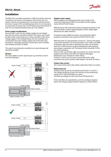
<strong>EKD</strong> <strong>316</strong> – ManualInstallationThe <strong>EKD</strong> <strong>316</strong> is normally mounted on a DIN rail, and the necessaryconnections are shown in the diagram. If the sensor S4 is notused to measure air temperature in connection with thermostatfunction or as part of the controlling loop, then it is not necessaryto connect the S4 sensor. The 18-24 V battery input at terminals 15and 16 is not required if battery back-up is not needed.Power supply considerationsThe terminals 1 and 2 for the voltage supply are not isolatedfrom the rest of the controller terminals. This means care shouldbe taken when connecting two or more controllers to the samevoltage supply. In the example below, the two controllers areconnected to the same voltage supply and on the input side,terminals 21 (Analogue Input) are connected to each controllerand similarly terminals 22 (GND).This way of connecting the controllers can cause damage andshould be avoided.Note:The same applies to other signal inputs e.g. terminals 2 and 4.See warning page 5.Stepper motor outputAfter installation the following checks can be made to theconnection between the <strong>EKD</strong> <strong>316</strong> controller and the steppermotor of the ETS 6/ETS valve.With the power off, check that resistance between terminals 5 and6 and terminals 7 and 8 is approximately 53 Ohms. Make slightallowances for cable resistance.If resistance values differ from above, ensure that the cable isproperly connected to the actuator of the ETS 6/ETS valve.With the power on and parameter o18 set to 1, measure the phasecurrent from terminal 5 (or 6) and terminal 7 (or 8 ) with a true RMSmultimeter when the valve is operating. The valve can be drivenfrom 0% to 100% and vice versa by changing the valve openingpercentage in parameter o45. The phase current should be 70 mArms when operating.If this not the case and the cable connections are correct, then thestepper motor driver in the <strong>EKD</strong> <strong>316</strong> might be damaged.Remember to set o18 back to 0 after checks.If checks 1) and 2) are not correct, ensure that motor cablecorrections are correct and the cable length is less than 30 meters.Output relay contactThe contact of the alarm relay will be made when there is an alarm.Battery back-upA battery back-up can be connected to terminals 3 (+) and 4 (-).The voltage should be at least 18 V and this can be achieved byusing two 9 V 100 mAh batteries in series.The back-up voltage can also come from UPS giving 24 V.If the controllers are operated by a common analogue signal asabove, the voltage supply should be separate as shown below.8 DKRCC.PS.RP0.A1.02/520H7142 ©Danfoss A/S (AC-MCI/MWA) 2013 - 03