Aquanet Plus
Aquanet Plus
Aquanet Plus

You also want an ePaper? Increase the reach of your titles
YUMPU automatically turns print PDFs into web optimized ePapers that Google loves.
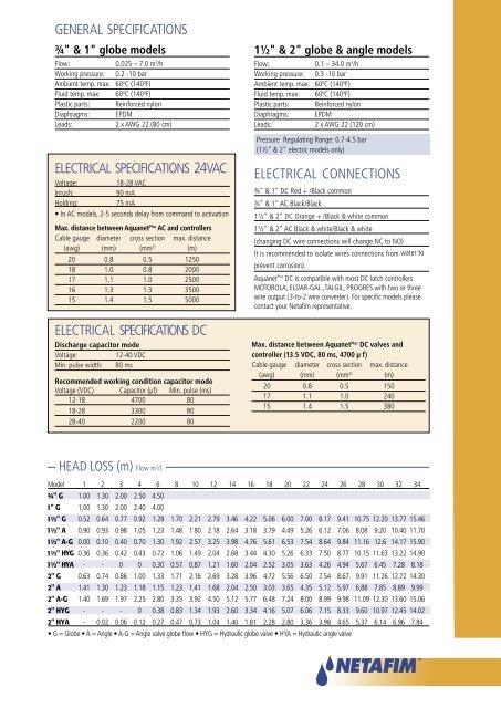
GENERAL SPECIFICATIONS¾" & 1" globe modelsFlow: 0.025 – 7.0 m 3 /hWorking pressure: 0.2 -10 barAmbient temp. max: 60 0 C (140 0 F)Fluid temp. max: 60 0 C (140 0 F)Plastic parts: Reinforced nylonDiaphragms: EPDMLeads:2 x AWG 22 (80 cm)ELECTRICAL SPECIFICATIONS 24VACVoltage:18-28 VACInrush:90 mAHolding:75 mA• In AC models, 2-5 seconds delay from command to activationMax. distance between <strong>Aquanet</strong> <strong>Plus</strong> AC and controllersCable gauge diameter cross section max. distance(awg) (mm) (mm 2) (m)20 0.8 0.5 125018 1.0 0.8 200017 1.1 1.0 250016 1.3 1.3 350015 1.4 1.5 5000ELECTRICAL SPECIFICATIONS DCDischarge capacitor modeVoltage:12-40 VDCMin. pulse width: 80 msRecommended working condition capacitor modeVoltage (VDC) Capacitor (µf) Min. pulse (ms)12-18 4700 8018-28 3300 8028-40 2200 801½" & 2" globe & angle modelsFlow: 0.1 – 34.0 m 3 /hWorking pressure: 0.3 -10 barAmbient temp. max: 60 0 C (140 0 F)Fluid temp. max: 60 0 C (140 0 F)Plastic parts: Reinforced nylonDiaphragms: EPDMLeads:2 x AWG 22 (120 cm)Pressure Regulating Range: 0.7-4.5 bar(1½" & 2" electric models only)ELECTRICAL CONNECTIONS¾" & 1" DC Red + /Black common¾" & 1" AC Black/Black1 ½" & 2" DC Orange + /Black & white common1 ½" & 2" AC Black & white/Black & white(changing DC wire connections will change NC to NO)It is recommended to isolate wires connections from water toprevent corrosion).<strong>Aquanet</strong> <strong>Plus</strong> DC is compatible with most DC latch controllersMOTOROLA, ELDAR-GAL ,TALGIL, PROGRES with two or threewire output ( 3-to-2 wire converter ). For specific models pleasecontact your Netafim representative.Max. distance between <strong>Aquanet</strong> <strong>Plus</strong> DC valves andcontroller (13.5 VDC, 80 ms, 4700 µf)Cable gauge diameter cross section max. distance(awg) (mm) (mm 2) (m)20 0.8 0.5 15017 1.1 1.0 24015 1.4 1.5 380HEAD LOSS (m) Flow m 3 /lModel 1 2 3 4 6 8 10 12 14 16 18 20 22 24 26 28 30 32 341.00 1.30 2.00 2.50 4.501.00 1.30 2.00 2.40 4.000.52 0.64 0.77 0.92 1.28 1.70 2.21 2.79 3.46 4.22 5.06 6.00 7.00 8.17 9.41 10.75 12.20 13.77 15.460.90 0.93 0.98 1.05 1.23 1.48 1.80 2.18 2.64 3.18 3.79 4.49 5.26 6.12 7.06 8.08 9.20 10.40 11.700.00 0.10 0.40 0.70 1.30 1.92 2.57 3.25 3.98 4.76 5.61 6.53 7.54 8.64 9.84 11.16 12.6 14.17 15.900.36 0.36 0.42 0.43 0.72 1.06 1.49 2.04 2.68 3.44 4.30 5.26 6.33 7.50 8.77 10.15 11.63 13.22 14.90- - 0 0 0.30 0.57 0.87 1.21 1.60 2.04 2.52 3.05 3.63 4.26 4.94 5.67 6.45 7.28 8.180.63 0.74 0.86 1.00 1.33 1.71 2.16 2.69 3.28 3.96 4.72 5.56 6.50 7.54 8.67 9.91 11.26 12.72 14.301.41 1.30 1.23 1.18 1.15 1.23 1.41 1.68 2.04 2.50 3.03 3.65 4.35 5.12 5.97 6.88 7.85 8.89 9.991.40 1.69 1.97 2.25 2.80 3.35 3.92 4.50 5.12 5.77 6.48 7.24 8.00 8.99 9.98 11.09 12.30 13.60 15.06- - - 0 0.38 0.83 1.34 1.93 2.60 3.34 4.16 5.07 6.06 7.15 8.33 9.60 10.97 12.45 14.02- 0.02 0.06 0.12 0.27 0.47 0.73 1.04 1.40 1.81 2.28 2.80 3.36 3.98 4.65 5.37 6.14 6.96 7.84• G = Globe • A = Angle • A-G = Angle valve globe flow • HYG = Hydraulic globe valve • HYA = Hydraulic angle valve