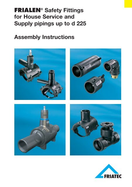
Friatec Electrofusion Assembly Instructions
Friatec Electrofusion Assembly Instructions
Friatec Electrofusion Assembly Instructions
Create successful ePaper yourself
Turn your PDF publications into a flip-book with our unique Google optimized e-Paper software.
WARNING!During processing, pipes and fittings should have a balanced temperaturelevel in the permissible range of application between -10°C and +45°C(fittings from d 710 between 0 °C and + 45 °C).IMPORTANT!FRIALEN ® Safety Fittings are identified by a batch marking.This reads from left to right:• Production week (KW) (stamp 1+2)• Production year (stamp 2)• Material identification letter (stamp 3)Example:3040500765180901JK L MA B CD E F G H I2010KW 14/01/E432TraceabilityAn automatic component traceability is possible when using e.g. traceabilitycapableFRIAMAT ® <strong>Electrofusion</strong> Units with a special barcode (see Fig. 9)which contains the specific data of the fitting, e.g. manufacturer, dimension,material, batch. These data on component traceability can be electronically archivedtogether with the fusion process data.IMPORTANT!Manual electrofusion units (without barcode reader), e.g. FWS 225, areno longer state-of-the art. Processing of FRIALEN ® Safety Fittings withthese units is thus no longer possible.3.1 Pressure load-bearing capabilityThe pressure load-bearing capability of FRIALEN ®PE 100 is determined by the identification SDR.Pipe outer diameter ø dSDR =Pipe wall thickness sSafety Fittings made of5
The design factor C (calculation coefficient for PE components) depends onthe area of application and the specifications (min. 1.25).Fitting material: PE 100 Water Gas(FRIALEN ® standard)SDR Stage maximum operating pressure maximum operating pressurein bar for new: C = 1.25 in bar for new: C = 217 10 511 16 107,4 25 -The parts are identified and usable with regard to their load-bearing capabilityaccording to the above table.For pressure classifications deviating from this identification, e.g. because offunction-related limitations for FRIASTOPP ® , the data on the fitting or in thetechnical data sheets are to be observed.DANGERFusion with escaping media is not permissible.4. Couplers, Elbows, T-Pieces d 20 - d 2254.1 Cutting to length of pipesCut off the pipe in a right angle to thepipe axis (see Fig. 1). A suitable tool isa PE pipe cutter or a saw withtoothing suitable for plastics.Fig. 1DANGER!A non-rectangular pipe cuttingmay cause the heating coil partiallynot being covered by the pipewhich may result in overheating,uncontrolled melt formation orself-ignition (see Fig. 2).Fig. 26
4.2 Measure fusion zone, markwith a FRIALEN ® markerand remove oxide layerFusion zone:For fittings in general the insertiondepth, i.e. the distance between thecoupler edge and the internal stop.For slide over couplers, the distancebetween the coupler edgeand the centre of the coupler.At first, remove contaminations fromthe pipe. A processing allowance ofapprox. +5mm in addition of theinsertion depth provides proof afterfusion that the oxide layer has beenremoved properly. Using a manualscraper or FRIALEN ® Scraper toolsFWSG (see Fig. 3-5), the oxide layer,which formed during on the surfaceof HDPE pipes and spigot fittingsduring storage, has to be removedcompletely directly before the assembly.Pipe spigots, e.g. at fittings DAA,DAV…, ball valves KH, KHP orthread connecting adapters UAN/UAM are to be prepared analogue tothe processing specifications forpipes.Rotational scraper tools are prescribedpursuant to DVS2207-1,Supplement 1, for the preparation ofPE-X pipes.An equal and seamless scraping isachieved by using FWSG scrapertools.FWSG 63 d 20 - d 63 (Fig. 3)FWSG 225 d 75 - d 225 (Fig. 4)FWSG SE d 63 - d 315* (Fig. 5)Fig. 3Fig. 4Fig. 5*Dimension-dependent units for the processing of pipe ends and saddlefusion areas (Fig. 5)7
WARNING!If the oxide layer is not removed completely, inhomogeneous, leakingfusion joints may result.A one-time, complete removal is sufficient (min. 0.15 mm). Damages to thepipe surface as e.g. axial grooves or scratches may not be located within thefusion zone.WARNING!An excessive swarf removal may result in an excessively large annulargap which either cannot or only insufficiently closed by fusion.Please thus regularly check the condition of the blade at the manualscraper and the wear of the scraper blade at the scraper tool. Wornblades must be replaced (see FRIALEN ® Info No. 1).Scraper tool Desired swarf thickness (mm) Wear limit (mm)FWSG 63 0.15 - 0.25 0.3FWSG 225 0.25 - 0.35 0.4FWSG SE ≤ d63 0.15 – 0.25 0.15 / 0.3FWSG SE > d63 – d225 0.25 – 0.35 0.15 / 0.4Please note that the indicated wearing margin applies to FRIALEN ®Safety Fittings. Where appropriate please observe manufacturers’indications.Filing or sanding are not permitted because contaminations are introduced.For a control of the complete surface removal over the entire surface, werecommend to apply marking (control) lines (see Fig. 3). If during scraping ofthe surface non-scraped areas occur at some points (e.g. in case of bundledcoil goods or oval pipes), these areas are to be reworked. The processedzone is to be protected against dirt, soap, grease, subsequently flowingwater and unfavourable effects of weather (e.g. moisture, frost formation). Donot touch the fusion zone again after scraping.8
WARNINGFRIALEN ® Safety Fittings with integrated heating coils guarantee optimalheat transfer through their exposed heating coils and may thus notbe scraped at the inside of the fitting.4.3 External and internal chamfering of the cutting edgeFor this purpose, the manual scraper is a suitable tool. Remove swarvesfrom within the pipe.4.4 Restoration of irregular /oval pipesPipes, in particular bundled coils anddrums, may loose their roundnessduring storage. If the pipe out-of-roundnessin the fusion zone area exceeds1.5% of d (outer diameter) oris > 3.0 mm, these pipes must be roundedin the fusion zone area. Pleaseuse rounding clamps for this purposewhich are installed at the endof the fusion zone (see Fig. 6).4.5 CleaningThe surfaces of the pipes to be fusedand the interior surfaces of theFRIALEN ® Safety Fittings must beabsolutely clean, dry and free fromany grease. These areas are to becleaned with a suitable cleaningagent and exclusively with absorbent,lint-free and non-dyed paperdirectly before the assembly and afterscraping (see Fig. 7).Fig. 6Fig. 7We recommend PE cleaning agents which meet the requirements of the testbasis DVGW-VP 603, e.g. AHK cleaning agents.When cleaning, ensure that no contaminations from the unscraped pipesurface are introduced into the fusion zone.9
WARNING!When using alcoholic cleaning agents, the alcohol percentage must beat least 99.8% according to DVGW-VP 603.The cleaning agent must be completely evaporated before starting thefusion process.Subsequently, re-apply marking line for the fusion zone width with theFRIALEN ® marker because this line was removed during scraping andcleaning. The joint surfaces must be clean and dry before installing thefitting. The cleaned fusion zone should not be touched with bare hands.Moisture in the area of the joint area, e.g. because of dew or frost, is to beremoved using suitable aids.The fusion fitting is to be removed from the packaging only directly beforethe planned processing. The packaging protects the fittings against externalinfluences during transport and storage.4.6 Positioning of insertion or pipe ends into the fittingWhen connecting FRIALEN ® Safety Fittings and pipes, it is to be ensuredthat the contact sockets for connecting the fusion plug are accessible. Donot jam when connecting. The FRIALEN ® Safety Fittings should be slippedon without using force. The processed insertion end must be inserted intothe fitting up to the mark. If needed, rounding clamps (see Fig. 6) are to beused.Repeated scraping may not be performed to remedy installation problemsdue to out-of-roundness!If the fitting cannot be slipped on without using force despite the abovedescribed procedure, a repeated scraping is permitted.A simple control of the high points is possible by installing the coupler andevaluating the annular gap.4.7 Ensuring a tension-free assembly of the componentsAll joints prepared for fusion must be tension-free. Pipes may not be positionedin the FRIALEN ® Safety Fitting under bending stress or self-load.After the installation on the pipe ends, it must still be possible to move thecouplers by hand.If required, the piping or the fitting is to be supported or suitable fixingfacilities are to be used. The tension-free fixing of the joint is to be maintaineduntil the cooling time stated on the barcode and in the table (see Item 4.9) isreached.10
Before starting the fusion process, check again based on the markingswhether the position of the pipe insertion end in the FRIALEN ® Safety Fittinghas shifted (correct, if required).WARNING!A non-tension-free or shifted jointmay result in an impermissiblemelt flow and a defective jointduring fusion (see Fig. 8).4.8 Carrying out fusionFig. 8WARNING!Only use fusion units which have been approved by the manufacturerwith regard to their function for the processing of FRIALEN ® SafetyFittings. See DVS 2207-1.The fusion parameters are containedin the main barcode affixed to theFRIALEN ® Safety Fitting. Whenusing fully automatic fusion units(e.g. FRIAMAT ® ), the parameters areentered into the fusion unit using thereader.Fig. 9The subordinated barcode containsthe data for component traceability(see information 2). This barcode is only to be read if the component traceabilityfunction is to be used. This requires suitable fusion units.The fusable pipe series are listed in the SDR labelling on the label.The fusion units automatically monitor the fusion process and control thesupplied energy in determined limits.11
INFORMATION:The fusion parameters are encodedon the barcode label in theform of a 24-digit figure (top), thedata for component traceability inthe form of a 26-digit column ofnumbers (bottom), and can alsobe entered manually into theFRIAMAT ® fusion unit using theemergency entry mode.Fig. 10For fittings with separate coils (seeFig. 10), each fitting side is to befused separately.For fittings with continuous coil,both fitting sides are to be fusedsimultaneously (see Fig. 11).For FRIALEN ® Safety Fittings equippedwith a fusion indicator, the latteronly indicates to the performedfusion process. The proper fusionprocess is, however, only indicatedby the fusion unit!After reading of the barcode, thefitting data are to be compared withthe data shown on the unit’s display.If they are identical, start fusion.Please observe the operating instructionof the FRIAMAT ® fusionunit.Avoid stress on the connecting spot.Fig. 11Fig. 12WARNING!Keep a distance of one meter to the fusion site during the fusion processfor general safety reasons.12
The obtained actual fusion time is to be compared with the target fusiontime on the unit and to be noted on the pipe or the FRIALEN ® Safety Fitting(see Fig. 12).With this identification it is ensured that no fusion point is overlooked.In case of doubt, a fusion can be repeated. But the joint surfaces must becooled down to ambient temperature before each renewed fusion. Pleasecontact for this purpose your local FRIALEN ® sales engineer by phone or theFRIALEN ® Hotline.4.9 Cooling times.The cooling time isa) the time which is required to cool down the component to the temperaturewhich facilitates the movement of the joint. This time is also listed on thebarcode and is identified by CT.b) the time which is required to cool down the component to the temperaturewhich facilitates the application of the full test or operating pressure.This is classified into pressure volumes of up to 8 bar and > 8 bar.Diameter Cooling time in minutes for FRIALEN ®in mmcouplers and fittingsCT Up to pressurising Up to pressurisinguntil the at up to 8 bar at > 8 barjoint may bemoved20 – 32 5 8 1040 – 63 7 15 2575 – 110 10 30 40125 – 140 15 35 45160 – 225 20 60 75Information:A piping may only be commissioned after successful pressure test (seeEN 805, EN 12007 and DVGW G 469, W 400).The guidelines of the DVGW leaflets for pressure tests, the Europeanstandards or the country-specific regulations are to be observed.13
5. Pressure Tapping Tees, Pressure Tapping ValvesFRIALEN ® Pressure Tapping Tees and Pressure Tapping Valves aresuitable to be used as branches for unpressurised and pressurised pipings.WARNING!Saddle components d 40 – d 75 cannot be processed with SDR 17 HD-PE pipes.For tapping-technical reasons, FRIALEN ® Pressure Tapping Tees can ingeneral not be processed with SDR 7.4 pipes, and pressure tappingvalves can in general not be processed with SDR 7.4 and SDR 9 pipes.Please read our fitting data sheetsor ask the FRIALEN ® applicationengineer.5.1 Measuring of fusion zone ofthe pipes (and the lateraloutlet spigot), marking andremoving oxide layerAt first, remove contaminations fromthe pipe.Fig. 13Fusion zone: is the pipe surfacecovered by the upper part (see Fig.13); in case of lateral outlets the insertiondepth at the smooth fusionend. Using a FRIALEN ® Scraper tool(see Fig. 14), the oxide layer, whichformed during on the surface duringstorage, has to be removed completelyfrom the area of the fusionzone directly before the assembly.A processing allowance of severalmillimetres in addition to the coveredFig. 14area provides proof after fusion thatthe oxide layer has been properly removed from the pipe.14
WARNING!If the oxide layer is not removed completely, leaking fusion joints mayresult.Worn blades of the scraper tool and manual scraper must be replaced.A one-time, complete removal is sufficient (min. 0.15mm). A uniform surfacewithout flattening and material grates at the pipe diameter should be the result.WARNING!Filing or sanding of the pipe is not permitted because contaminationsare introduced.For a control of the complete surface removal over the entire surface, werecommend to apply marking (control) lines. If during scraping of the surfacenon-scraped areas occur at some points, these areas are to be reworked.The processed zone is to be protected against dirt, soap, grease, subsequentlyflowing water and unfavourable effects of weather (e.g. moisture,frost formation).5.2 CleaningThe surfaces of the pipes to be fused and the interior surfaces of theFRIALEN ® Safety Fittings must be absolutely clean, dry and free from anygrease. These areas are to be cleaned with a suitable cleaning agent andexclusively with absorbent, lint-free and non-dyed paper directly beforethe assembly and after scraping. We recommend PE cleaning agents whichmeet the requirements of the test basis DVGW-VP 603, e.g. AHK cleaningagents.When cleaning, ensure that no contaminations from the unscraped pipesurface are introduced into the fusion zone.WARNING!When using alcoholic cleaning agents, the alcohol percentage must beat least 99.8% according to DVGW-VP 603.15
The cleaning agent must be completely evaporated before starting thefusion process.Subsequently, re-apply marking line for the fusion zone width with theFRIALEN ® marker because this line was removed during scraping andcleaning. The joint surfaces must be clean and dry before installing thefitting. The cleaned fusion zone should not be touched with bare hands.Moisture in the area of the joint area, e.g. because of dew or frost, is to beremoved using suitable aids.The fusion fitting is to be removed from the packaging only directly beforethe planned processing. The packaging protects the fittings against externalinfluences during transport and storage.5.3 <strong>Assembly</strong>- Loosen pre-mounted screws onone side.- Open upper and lower part; stillscrewed side serves as hinge.- Place onto processed pipe area.- Tighten all four screws equallycross-wise up to the stop usingan Allen wrench (see Fig. 15).Allen wrenchSW 5SW 6Fitting≤ d63> d63Fig. 15Bottom parts are a component part of the fittings and serve the application ofthe joining pressure.WARNING!For pressure tapping tees and pressure tapping valves, the factory drillsetting may not be changed before starting the fusion process.5.4 Carrying out of fusionWhen fusing Pressure Tapping Tees and Valves to media-carrying pipings,the following operating pressures may not be exceeded until the pipe hascooled down completely:16
Pipe material PE 80 PE 100SDR 17 11 17 11Maximum permissible operating pressure in barGas pipe 1 4 5 10Water pipe 7 12,5 10 16WARNING!Only use fusion units which have been approved by the manufacturerwith regard to their function for the processing of FRIALEN ® SafetyFittings. See DVS 2207-1.The fusion parameters are contained in the main barcode affixed to theFRIALEN ® Safety Fitting. When using fully automatic fusion units (e.g.FRIAMAT ® ), the parameters are entered into the fusion unit using the reader.After reading of the barcode, the fitting data are to be compared with thedata shown on the unit’s display. If they are identical, start fusion. Pleaseobserve the operating instruction of the FRIAMAT ® fusion unit.A pressure test of the branch line can be performed before tapping themain line.The fusion units automatically monitor the fusion process and control thesupplied voltage in determined limits.The swell indicator only indicates to the performed fusion process. Theproper fusion process is, however, only indicated by the fusion unit!WARNING!Keep a distance of one meter to the fusion site during the fusionprocess for general safety reasons.The obtained ACTUAL fusion time is to be compared with the target fusiontime on the unit and to be noted on the pipe or the FRIALEN ® Safety Fittings.With this identification it is ensured that no fusion point is overlooked.17
5.5 Tapping and application of the test and operating pressureThe following waiting times are to be observed:Diameter Cooling time in minutes for FRIALEN ®in mmSaddle fittingsUp to pressurisationvia outletCTUp totapping40 – 63 15 2075 – 125 20 30140 – 160 30 45180 – 225 50 60The cooling time CT stated on the components corresponds to the coolingtime until tapping.WARNING!If the waiting times are not observed, leaking fusion joints may result.The general installation instructions must be observed before tapping.5.6 Tapping of Pressure TappingTeesRemove blanking plug. Turn the drilldown up to the lower stop using thematching FRIALEN ® activating key(see Fig. 16).ø diSW40 1063 17≥ 90 19Fig. 16Turn the drill backwards up to the upper stop.Position the blanking plug and turn down the FRIALEN ® activating key untilthe collar of the plug slightly touches the front face of the drill spigot.Subsequently, turn back the plug half a turn to relieve the O-ring tension.18
WARNING!If the collar is excessively tightened, the plug may break or the hexagonalseat may be overwound. In this case, the plug has to be replaced.We recommend closing the tapping dome with a fusion cap K. Therequired scraping and cleaning are to be performed (see Chapter 4.1 - 4.9).5.7 Tapping of Pressure TappingTees with parallel outletTapping (see Fig. 17) is made analogueto Item 5.6 with the activatingkey for pressure tapping tees withparallel outlet.5.8 Tapping of Pressure TappingValvesInstallation, fusion and cooling timesas 5.1 et seq.Tap with a suitable key via the 14mmsquare turning clockwise (see Figs.17 and 18) until the lower stop is reached.The valve is now closed. In orderto open the valve, the drill has tobe turned anti-clockwise until thestop. The metallic stops for the positions“open” and “closed” of the valveresult in a clearly noticeably increasein the activation force.Because sealing in the closed stateis made through a radially pressedO-ring, an excessive closing is notrequired.Fig. 17Fig. 1819
INFORMATION:A subsequent tapping from the surface box using the FRIALEN ® EBS ispossible.Connect the 14mm square of the pressure tapping valve to the FRIALEN ®installation kit EBS and protect with a cotter pin against coming loose.Adjust the required covering height at the extendable activation rods. Thetelescopic rods can be adjusted continuously and is fixed safely at itsextension position. The FRIALEN ® EBS is technically optimally matched tothe FRIALEN ® pressure tapping valve.6. Valve Tapping Saddles6.1 <strong>Assembly</strong>The preparation of the installationand the fusion process is made analogueto the FRIALEN ® PressureTapping Tee (see 5.1 - 5.4).The cooling times are to be observed(see item 5.5 Pressure TappingTee).Fig. 19The tee is tapped with a corresponding lock assembly or installed witha valve according to the installation instructions of the different valvemanufacturers. The preparation and performance of the pressure test ismade according to the valve manufacturer’s instructions.The factory-installed metallic torque parts must be protected againstturning out of position using a key.IMPORTANT!The insulation work has to be carried out properly (DVGW regulations).20
7. Shut-off Saddles7.1 <strong>Assembly</strong>FRIALEN ® Shut-off Saddles (seeFig. 20) are prepared for installationand welded analogue to FRIALEN ®Pressure Tapping Tees (see Chapters5.1 – 5.4). The tapping of thepipe can be made after coolingdown (see Item 5.5) and observingthe installation instructions of thetapping/shut-off saddle installationequipment of the relevant manufacturer.Installing the brass plugThe plug is to be installed up to thestop; the O-ring must seal in thedome. The required torque of approx.150 Nm can be achievedthrough a lever. A visual controltakes place (Fig. 21). A torquescrewdriver is not necessary.Fig. 20Fig. 21Having installed the brass plug, eitherthe plastics cap has to bescrewed in or a FRIALEN ® Cap forShut-off Saddles SPAK (for SPAd 63, K d 50 has to be fused, takinginto consideration the usual scrapingand cleaning (Fig. 22).Fig. 2221
8. Spigot Saddles8.1 <strong>Assembly</strong>The preparation of the installationand the fusion process is made analogueto the FRIALEN ® PressureTapping Tee (see 5.1 - 5.4).WARNING!Fig. 23The tapping is made with commercially available tapping units in an unpressurisedstate with or under pressure using shut-off valves.We recommend the tapping unit of the company of Hütz + Baumgarten,Remscheid (www.huetz-baumgarten.de), especially designed for this purpose.Please ask our FRIALEN ® Application Engineering Department.The manufacturer’s installation instructions are to be observed.9. Reinforcement and repair saddles9.1 <strong>Assembly</strong>In case of selective pipe damages,the damaged area can be closedwith a plug and then fused with thereinforcement and repair saddle.Each half shell is to be fused separately.The preparation of the installationand the fusion process of the individualhalf shells is made analogueto the FRIALEN ® Pressure TappingTee (see 5.1 - 5.5).Fig. 24WARNING!Care must be taken to ensure that during assembly the damaged ordeformed point on the pipeline lies in the centre of the heating element.22
10. FRIALOC PE shut-off valve10.1 Areas of applicationFRIALOC PE shut-off valves made ofPE 100 can be used in water supplysystems according to DVGW (GermanTechnical and Scientific Associationfor Gas and Water) W400-2and EN 805 with a maximum componentpart operating pressure PFA(PN) of 16 bar.FRIALOC PE shut-off valves meetthe requirements on componentparts for use in water supply systemsaccording to DIN EN 12201-4and DVGW VP645.Fig. 25The approval for use in gas supply according to DVGW G472 and EN 12207-2 is being prepared (status: 01/08).For the planned installation of FRIALOC PE shut-off valves into other pipingsystems, please state the flow medium and the operating conditions (pressure,temperature, planned period of use…) to clarify if our application technologyis suitable.The preferred type of installation of FRIALOC PE shut-off valves is a material-homogeneousinstallation in PE piping systems using FRIALEN ® safety fittings.Using the fusion flanges FRIALEN ® EFL, installation into pipings madeof other materials is also possible. When using mechanical joining methods,e.g. FRIAGRIP, the specific installation instructions are to be observed.FRIALOC PE shut-off valves can be both buried or installed in systemsabove ground.Information:For up-to-date and detailed information on FRIALOC PE shut-off valves,please see the technical datasheets available on the Internet(www.frialen.com).23
10.2 IdentificationFRIALOC PE shut-off valves possessa coloured identification ringwhich contains information about dimension,pressure range etc. as wellas the individual component partnumber. With the help of these componentpart numbers, the data of theinstallation process archived by thecompany, including the batch dataof the component parts used andthe accompanying tests can betraced. Within the scope of the accompanyingtests, each individual Fig. 26FRIALOC PE shut-off valve is testedfor leak-tightness, strength, function, and actuation torque in a multilevelprocess. The individual component part number may also be automaticallyarchived in the FRIAMAT ® fusion protocol by reading the traceability bar codeon the fitting.10.3 StorageFRIALOC PE shut-off valves are supplied in a packaging made of cardboardand are to be stored in a dry place, protected against contamination, hightemperatures, and damage.10.4 Processing instructionsPlease check that the component part is in perfect condition when deliveredbefore installing it. Damaged valves may not be installed. The pipe connectingcouplers of the FRIALOC PE shut-off valves have a double fusion length andcorrespond in the joining area to the geometric requirements on PE pipes accordingto DIN EN 12201-2.In order to prevent contaminations,the protective covers should onlybe removed from the pipe connectingcouplers directly before installation.The connection is made byFRIALEN ® fusion according to theprocessing specifications of theseinstallation instructions or specificprocession instructions.The FRIALOC PE shut-off valve isequipped with an identification disk(Fig. 27) which can be installed at theactuation rods in the surface boxFig. 2724
and which contains information about the sense of rotation as well as the torquesfor opening and closing of the valve.A bottom plate can be used to increase the support area of the FRIALOC PEshut-off valve in the ditch bottom. The bottom plate made of PE is installed atthe four supports of the FRIALOC PE shut-off valve by using suitable screws.The valve may not be designed as fixed point of the piping to absorb forcessuch as e.g. flow impulses because of change of direction of the flowing materialor because of thermal elongation of the pipes.The valve must be sufficiently covered before working with the usual groundcompacting devices.10.5 TestPressure testThe piping is subjected to a pressure test according to W400-2, which mayonly be performed with fully opened valve (as delivered).FlushingThe piping is flushed according to W400-2 with opened valve.10.6 OperationThe FRIALOC PE shut-off valve is closed clockwise (closing to the right) andopened anti-clockwise.The sense of rotation and the number of torques for actuation may be readfrom the identification disk in the surface box (see 10.4).The FRIALOC PE shut-off valves are not designed for continuous controllingof the flow.The final “open” and “closed” position of the FRIALOC PE shut-off valve isclearly signalled to the user by metallic stops.The desired coverage height can be freely adjusted telescopically with theFRIALEN ® actuation rods FBS and overstressing of the valve drive is thusprevented. FRIALOC and FBS are ideally matched.When installing in systems, the FRIALOC PE shut-off valve is operated viathe hand wheel FHR. The hand wheel is directly installed on the spindlesquare.10.7 MaintenanceFRIALOC PE shut-off valves are maintenance-free. The inspection intervalsaccording to DVGW-leaflet W392 are to be observed.25
11. Ball ValvesThe FRIALEN ® Ball Valve KH/KHP(see Fig. 28) closes and opens by a1/4 turn of the activating element.The FRIALEN ® Ball Valve KH/KHPis connected to the piping with itsHDPE fusion ends using FRIALEN ®Couplers, Elbows or T-pieces. It issuitable both for selective networkisolation as well as for isolatinghouse service pipings.Fig. 2811.1 <strong>Assembly</strong>The fusion ends are prepared according to the general installation requirements(remove oxide layer/clean). Before starting the fusion process, theFRIALEN ® Ball Valve head KH/KHP must be aligned corresponding to theplanned actuation to guarantee a correct positioning of the activation rod BS.The extendable FRIALEN ® Installation Kit BS has been especially designedfor the technical and geometric demands of the KHP Ball Valve.WARNING!Media identification and closing direction can be marked on the surfacebox using a marking disk.12. Tapping Ball Valves12.1 <strong>Assembly</strong>The preparation of the installationand the fusion process of the tappingball valve AKHP (Fig. 29) is made assaddle component analogue to theFRIALEN ® Pressure Tapping Tee(see Items 5.1 - 5.5).Fig. 2926
INFORMATION:For a leakage-free tapping of pressurised pipings, we recommendthe tapping unit of the company of Hütz + Baumgarten, Remscheid(www.huetz-baumgarten.de). Please ask our Application EngineeringDepartment.13. Transition Fittings13.1 <strong>Assembly</strong>WARNING!When removing the PE protectionlid, please ensure that the wire isnot damaged.The general installation instructionsfor the FRIALEN ® SafetyFittings (see Chapters 4.1 - 4.9)are to be observed.13.2 Transition Fittings with steelpipeFig. 30WARNING!In addition, the following items are to be considered:- A shortening of the steel pipe is impermissible because the heat introductionduring fusion has a negative effect on the sealing system.- Fusion of the steel side only by arc welding.- When fusing the steel end it has to be prevented that fusion vapour andfusion beads get into or to the FRIALEN ® Coupler with integrated heatingcoil.27
Prevention:Insert HDPE pipe section, whichcan be removed afterwards, intothe FRIALEN ® Coupler withoutusing force and close at pipe endto prevent any suction effects.The insulation is to be made accordingto the valid regulations as wellas the manufacturer’s instructions.The barcode may not be covered bythe insulation.Fig. 31FRIALEN ® Transition Fittings withsteel pipe (only for gas applications,see Fig. 31).13.3 Transition Fittingswith threaded connectionGas steel thread (Fig. 32)Water Brass/gunmetal thread(Fig. 33)During the further course of installation,the factory-installed metallicthreaded parts must be protectedwith a key against turning out ofposition in the plastics component.Fig. 32WARNING:The threaded connection mayabsolutely not be metallicallyfused or soldered. For insulationto be made, if any, Chapter 13.2applies.Fig. 3328
14. Repair Sleeves forpipes d 32 – d 63,SDR 11WaterThe sleeve (Fig. 34) prevents thesubsequent flow of residual waterinto the fusion zone during repair orconnection to house service pipingsfor water (Fig. 35).14.1 <strong>Assembly</strong>For a repair of the damaged waterpipe, a fitting piece with two slideover couplers FRIALEN ® UB andtwo repair sleeves FRIALEN ® RW isprepared.The water pipe has to be bendcorrespondingly to install the fittingpiece. Having positioned the slideover couplers, fusion is made analogueto Items 4.2-4.9.Fig. 34Fig. 3529
15. Update of these assembly instructionsFurther operating and assembly instructions are available:- FRIALEN ® Large Pipe Engineering and Pipe Network Relining- FRIAFIT ® Sewage System- FRIAMAT ® <strong>Electrofusion</strong> Units- FRIATOOLS ® Scraper Tools- FRIATOP Clamping Unit- FWFIT Clamping and Tapping ToolThese technical statements are regularly revised to be up-to-date. The dateof the last revision is stated on the document.For an updated version of the operating instructions, please visit our websitewww.frialen.com on the Internet. You will find the “Download” page on thenavigation bar. This page contains our updated operating instructions as pdfdocuments. We will also mail them to you on request.30
FRIATEC Aktiengesellschaft · Technical Plastics DivisionP.O.Box 71 02 61 · D-68222 MannheimPhone: +49 621 486-1486 · Fax: +49 621 479196E-Mail: info-frialen@friatec.de · www.frialen.com2283/7e · 2 · I.08 · ABT· Update: 22.01.200832


