the epocast marine handbook - HA SPRINGER - marine + industrie ...
the epocast marine handbook - HA SPRINGER - marine + industrie ...
the epocast marine handbook - HA SPRINGER - marine + industrie ...

You also want an ePaper? Increase the reach of your titles
YUMPU automatically turns print PDFs into web optimized ePapers that Google loves.
H.A. <strong>SPRINGER</strong> GMBH<br />
AN ILLINOIS TOOL WORKS COMPANY EPOCAST MARINE <strong>HA</strong>NDBOOK<br />
Info 6 - 94 - 1 - EP – E<br />
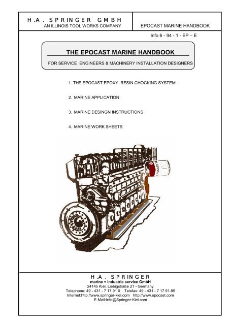
THE EPOCAST MARINE <strong>HA</strong>NDBOOK<br />
FOR SERVICE ENGINEERS & MACHINERY INSTALLATION DESIGNERS<br />
1. THE EPOCAST EPOXY RESIN CHOCKING SYSTEM<br />
2. MARINE APPLICATION<br />
3. MARINE DESINGN INSTRUCTIONS<br />
4. MARINE WORK SHEETS<br />
H.A. <strong>SPRINGER</strong><br />
<strong>marine</strong> + <strong>industrie</strong> service GmbH<br />
24145 Kiel, Liebigstraße 21 - Germany<br />
Telephone: 49 - 431 - 7 17 91 0 Telefax: 49 - 431 - 7 17 91-95<br />
Internet:http://www.springer-kiel.com http://www.<strong>epocast</strong>.com<br />
E-Mail:Info@Springer-Kiel.com
H.A. <strong>SPRINGER</strong> GMBH<br />
AN ILLINOIS TOOL WORKS COMPANY EPOCAST MARINE <strong>HA</strong>NDBOOK<br />
C O N T E N T S<br />
1.0. THE EPOCAST EPOXY RESIN CHOCKING SYSTEM<br />
1.1. W<strong>HA</strong>T IS AN EPOXY RESIN CHOCK?<br />
1.2. HOW LONG <strong>HA</strong>VE RESIN CHOCKS BEEN IN USE?<br />
1.3. W<strong>HA</strong>T IS EPOCAST?<br />
1.4. W<strong>HA</strong>T ARE THE BENEFITS OF USING EPOCAST 36?<br />
1.5. W<strong>HA</strong>T IS H.A. <strong>SPRINGER</strong> GMBH?<br />
1.6. WHERE IS H.A. <strong>SPRINGER</strong> GMBH?<br />
1.7. HOW IS EPOCAST INSTALLED?<br />
1.8. WHO SUPPLIES AND INSTALLS EPOCAST?<br />
1.9. W<strong>HA</strong>T IS THE SHELF LIFE OF EPOCAST 36?<br />
1.10. W<strong>HA</strong>T ARE THE OPERATING LIMITS OF EPOCAST CHOCKS?<br />
1.11. W<strong>HA</strong>T ARE THE LIMITS FOR CHOCK THICKNESS?<br />
1.12. DO WE NEED TO MAKE A TRIAL CHOCK BEFORE POURING?<br />
1.13. HOW DO WE FIT THE REAMER BOLTS?<br />
1.14. ARE THERE SPECIAL REQUIREMENTS FOR HOLDING DOWN BOLTS?<br />
1.15. HOW DO WE ADJUST ALIGNMENT AFTER POURING?<br />
1.16. IS EPOCAST FLEXIBLE?<br />
1.17. W<strong>HA</strong>T IS THE LIFE OF RESIN CHOCKS?<br />
1.18. IS IT DIFFICULT TO LEARN HOW TO USE EPOCAST?<br />
1.19. HOW DO WE DESIGN AN EPOCAST INSTALLATION?<br />
1.20. IS THERE A GUARANTEE?<br />
1.21. HOW DO WE ORDER EPOCAST 36?<br />
2 .0 . MARINE APPLICATION INSTRUCTIONS<br />
2.1. EPOCAST CHOCKING MATERIALS REQUIRED<br />
2.2. PROCEDURE<br />
2.3. MIXING AND POURING<br />
2.4. TEST PIECE<br />
2.5. AFTER POURING<br />
2.6. EPOCAST APPLICATION IN SUB-ZERO CONDITIONS<br />
2.7 RECORD CARD<br />
2.8 REPAIRS TO FAULTY CHOCKS
H.A. <strong>SPRINGER</strong> GMBH<br />
AN ILLINOIS TOOL WORKS COMPANY EPOCAST MARINE <strong>HA</strong>NDBOOK<br />
3 .0 . MARINE DESIGN INSTRUCTIONS<br />
3.1. INTRODUCTION<br />
3.2. EPOCAST 36® AND EPOCAST D<br />
3.3. THICKNESS<br />
3.4. BEDPLATE AREAS TOO SMALL<br />
3.5. SPREADER PLATE<br />
3.6. MIXING IRON AND RESIN CHOCKS<br />
3.7. SMALL CHOCKS<br />
3.8. CHOCK LENGTH<br />
3.9. COMPRESSION ON BOLTING DOWN<br />
3.10. CRITICAL ALGINMENT DESIGN RULES<br />
3.11. PLANS FOR CLASSIFICATION SOCIETY APPROVAL<br />
3.12. BOLT STRETCH<br />
3.13. TO FIND BOLT TORQUE OR TENSION<br />
3.14. TO FIND HYDRAULIC PRESSURE TO TENSION BOLTS<br />
3.15. FITTED BOLTS<br />
3.16. CONTACT H.A. <strong>SPRINGER</strong> GMBH FOR CALCULATIONS & DRAWINGS<br />
3.17. UNIFORM LOAD DISTRIBUTION<br />
3.18. NON-CRITICAL ALIGNMENT DESIGN RULES<br />
3.19. WHEN TO USE EPOCAST D<br />
3.20. OTHER APPLICATIONS<br />
3.21. STRENGTH OF BOLTS<br />
4.0 . MATERIALS, TOOLS AND TEST EQUIPMENT<br />
Proprietary Rights<br />
This <strong>handbook</strong> shall not be copied, reproduced or translated<br />
in part or in whole without <strong>the</strong> prior written permission of<br />
H.A. <strong>SPRINGER</strong> GmbH.<br />
Copyright (c) H.A. <strong>SPRINGER</strong><br />
<strong>marine</strong> + <strong>industrie</strong><br />
service GmbH<br />
Liebigstraße 21<br />
D-24145 Kiel - Germany
H.A. <strong>SPRINGER</strong> GMBH<br />
AN ILLINOIS TOOL WORKS COMPANY EPOCAST MARINE <strong>HA</strong>NDBOOK<br />
1.0. THE EPOCAST EPOXY RESIN CHOCKING SYSTEM<br />
1.1. W<strong>HA</strong>T IS AN EPOXY RESIN CHOCK?<br />
Metal chocks and shims have been used for many years to adjust<br />
<strong>the</strong> height and alignment of propulsion machinery. This requires<br />
skilled work and takes time. Epoxy resin chocks are used for <strong>the</strong><br />
same purposes. They require less skill and less time to<br />
install, yet <strong>the</strong>y perform better than iron chocks.<br />
An epoxy resin chock is an engineering product which is<br />
cast-in-place to form permanent chocks for machinery support. It<br />
can be specified for chocking hot vibrating machinery, or<br />
critical alignment installation. A resin chock gives a better<br />
result for a longer period than a conventional iron chock. The<br />
basis of <strong>the</strong> success of resin chocks is <strong>the</strong> low modulus and near<br />
perfect cast-in-suit fit over a large surface area, combined with<br />
a high coefficient of friction and a high coefficient of <strong>the</strong>rmal<br />
expansion. These toge<strong>the</strong>r hold machinery securely, permanently,<br />
and without fretting or wear to <strong>the</strong> chock contact surfaces.<br />
Resin chocks are economical and convenient for newbuilding<br />
installation or for retrofits, due to <strong>the</strong> absence of any<br />
requirement for machining. Installation time is measured in days<br />
ra<strong>the</strong>r than in weeks normally required for iron chocking. It is<br />
used widely for <strong>marine</strong> main engines of any size, auxiliaries,<br />
steering gear, deck machinery and crane rails. Industrially it<br />
is used for generators, compressors, crushers and a wide range of<br />
grouting applications.<br />
1.2. HOW LONG <strong>HA</strong>VE RESIN CHOCKS BEEN IN USE?<br />
Epoxy resin chocks for mounting machinery have been used in<br />
shipyards around <strong>the</strong> world since <strong>the</strong> early 1970’s in approxi-<br />
mately 30,000 applications; proving <strong>the</strong> reliability and superior<br />
performance of resin chocks over traditional metal chocks. Many<br />
shipyards have experience with this system.<br />
1.3. W<strong>HA</strong>T IS EPOCAST?<br />
EPOCAST 36® is <strong>the</strong> registered trade name of <strong>the</strong> modern pourable<br />
epoxy resin chocking system developed and manufactured by H.A.<br />
<strong>SPRINGER</strong> GMBH, and distributed worldwide directly from our<br />
factory. As we are specializing in this business we are able to<br />
give good service at economical prices.
H.A. <strong>SPRINGER</strong> GMBH<br />
AN ILLINOIS TOOL WORKS COMPANY EPOCAST MARINE <strong>HA</strong>NDBOOK<br />
1.4. W<strong>HA</strong>T ARE THE BENEFITS OF USING EPOCAST 36® ?<br />
BE<strong>HA</strong>VIOUR<br />
There are several features or characteristics of EPOCAST 36®<br />
pourable chocking compound which differ from iron chocks. These<br />
give EPOCAST 36® a special ‘behaviour’ which gives tangible<br />
benefits.<br />
FEATURES<br />
Low modulus of elasticity.<br />
Low modulus of rigidity.<br />
Low poissons ratio.<br />
High coefficient of <strong>the</strong>rmal expansion.<br />
High coefficient of friction.<br />
Poured into place.<br />
Inert (does not corrode).<br />
Low exo<strong>the</strong>rm (does not overheat when setting).<br />
Low volumetric shrinkage.<br />
Large surface contact area.<br />
Relatively uniform loading over <strong>the</strong> chock surface.<br />
The chock can bend with <strong>the</strong> bedplate in a seaway.<br />
Mechanical lock into surface irregularities.<br />
Accepts small relative movement between bedplate and<br />
foundation by distorting <strong>the</strong> chock.<br />
There is no fretting or pouring.<br />
As <strong>the</strong> engine warms up chock expands more than steel causing<br />
chock security to improve.<br />
Chock material attenuates <strong>the</strong> transmission of noise.<br />
Chock does not corrode.<br />
Can mix chocks in hot conditions.<br />
Can form large chocks in one pour.<br />
Generally <strong>the</strong> SHIPOWNER benefits from having machinery securely<br />
mounted on a system requiring minimum maintenance. The owner<br />
knows his machinery is not going to require rechocking during<br />
<strong>the</strong> normal service life of a ship.<br />
The SHIPYARD knows it is economical and convenient to use resin chocks<br />
and that may owners now specify resin chocks in <strong>the</strong> light of<br />
operational experience.<br />
The benefits are fully listed on <strong>the</strong> next page.
H.A. <strong>SPRINGER</strong> GMBH<br />
AN ILLINOIS TOOL WORKS COMPANY EPOCAST MARINE <strong>HA</strong>NDBOOK<br />
BENEFITS FROM GOOD RESIN CHOCKS<br />
CHOCKS DO NOT FRET OR WEAR.<br />
LESS RISK FROM NEGLECT OF BOLT TENSION IN SERVICE.<br />
LESS LOOSE OR BROKEN BOLTS.<br />
LESS FATIGUE FRACTURES OF PIPEWORK.<br />
LESS NOISE TRANSMISSION AND LESS VIBRATION TO HULL.<br />
NO MACHINING TO THE FOUNDATION.<br />
NO MACHINING OR SKILLED <strong>HA</strong>ND FITTING OF CHOCKS.<br />
EASY QUALITY CONTROL.<br />
WORK TAKES DAYS NOT WEEKS.<br />
WORK TIME CAN BE ACCURATELY SCHEDULED.<br />
SHORTER BUILDING PERIOD SAVES INTEREST C<strong>HA</strong>RGES/PENALTIES.<br />
APPROVED BY ALL CLASSIFICATION SOCIETIES.<br />
ACCEPTED BY ALL MAJOR ENGINE BUILDERS.<br />
SPECIAL BENEFITS FROM EPOCAST 36 RESIN CHOCKS<br />
EPOCAST 36® IS STABLE WITH VIRTUALLY NO CREEP GIVING A PERMANENT<br />
INSTALLATION. EPOCAST 36® WAS THE FIRST RESIN CHOCK TO OBTAIN<br />
APPROVAL FOR USE UNDER HOT MEDIUM SPEED ENGINES WITH BEDPLATE<br />
TEMPERATURES UP TO 80°C.<br />
EPOCAST 36® IS CAPABLE OF CASTING LARGE THICK CHOCKS IN ONE HOMO-<br />
GENEOUS POUR. THIS SAVES HUNDREDS OF DOLLARS AND HOURS OF<br />
TIME. IT IS PREFERABLE TO FORM CHOCKS IN ONE POUR TO AVOID THE RISK OF<br />
CURLING OR DELAMINATION.<br />
EPOCAST 36® MIXING AND POURING IS PARTICULARILY SIMPLE MAKING<br />
EPOCAST 36® THE IDEAL CHOCKING COMPOUND FOR APPLICATION BY SHIP-<br />
YARD STAFF WHO <strong>HA</strong>VE BEEN TRAINED AND CERTIFICATED BY<br />
H.A. <strong>SPRINGER</strong> GMBH.<br />
EPOCAST 36 CAN BE MIXED AT A HIGHER TEMPERATURE ALLOWING FAST<br />
MIXING, MINIMUM ENTRAPMENT OF AIR, AND PRECISE CONTROL OF THE<br />
INITIAL REACTION TO ENSURE GOOD QUALITY CHOCKS.<br />
EPOCAST 36® WHEN MIXED AT THE CORRECT TEMPERATURE CAN<br />
GENERALLY BE POURED ONTO COLD STEEL. THIS AVOIDS DELAYS<br />
REQUIRED TO PREHEAT THE FOUNDATION AND AVOIDS THE RISK OF<br />
DISTURBING THE ALIGNMENT. IF POST CURE IS REQUIRED APPLY HEAT<br />
AFTER THE CHOCKS ARE POURED.<br />
EPOCAST 36® CHOCK ARRANGEMENTS ARE APPROVED BY ENGINE<br />
MAKERS, AND CHECKED AND STANDARDIZED BY OUR OFFICE IN KIEL.<br />
EPOCAST 36® TECHNICAL SERVICE IS AVAILABLE WORLDWIDE. THE SYSTEM<br />
ALLOWS TRAINED CERTIFICATED YARD STAFF TO DO THE INSTALLATIONS<br />
THEMSELVES.
H.A. <strong>SPRINGER</strong> GMBH<br />
AN ILLINOIS TOOL WORKS COMPANY EPOCAST MARINE <strong>HA</strong>NDBOOK<br />
1.5. W<strong>HA</strong>T IS H.A. <strong>SPRINGER</strong>-KIEL?<br />
H.A. <strong>SPRINGER</strong> <strong>marine</strong> + <strong>industrie</strong> service GmbH is a wholly<br />
owned private limited company which develops, manufactures<br />
and markets special purpose products as required by<br />
customers. Our <strong>marine</strong> division has EPOCAST 36® and<br />
EPOCAST D for chocking; EPOCAST 36-P for cryogenic tank<br />
mountings and vertical grouting and EPOCAST S for socketing<br />
of wire ropes.<br />
CELLOFLEX for external propeller shaft coatings.<br />
Our industrial division has EPOCAST 36®, EPOCAST G, and<br />
EPOCAST PI for mounting stationary diesels and o<strong>the</strong>r<br />
plants EPOCAST CR for crane rail chocking. We have a policy<br />
of research into customer needs and technical solutions:<br />
“RESEARCH MAKES THE DIFFERENCE”.<br />
1.6. WHERE IS H.A. <strong>SPRINGER</strong> GMBH?<br />
H.A. <strong>SPRINGER</strong> GMBH is in Kiel, a city in <strong>the</strong> north of<br />
Germany and on <strong>the</strong> Baltic coast. It is <strong>the</strong> gateway to<br />
Scandinavia and well placed for close contacts with Euro-<br />
pean shipowners, many engine builders, including <strong>the</strong> two<br />
majors MAN-B&W and SULZER, and many Classification Socie-<br />
ties.<br />
1.7. HOW IS EPOCAST INSTALLED?<br />
The principle is simple. The engine or machinery is<br />
aligned on wedges or jacking screws and <strong>the</strong> steel surfaces<br />
cleaned. Soft foam shuttering or damming is inserted to<br />
form <strong>the</strong> sides of <strong>the</strong> mould under <strong>the</strong> bedplate, metal damm-<br />
ing is used to form <strong>the</strong> external side of <strong>the</strong> mould and to<br />
form a pouring space. Release agent is sprayed in, bolt<br />
holes are plugged.<br />
The steel is generally not heated before pouring. THIS IS A<br />
UNIQUE FEATURE OF EPOCAST SAVING TIME AND<br />
REDUCING THE RISK OF MISALIGNMENT. The resin is<br />
warmed to <strong>the</strong> required temperature and <strong>the</strong> hardener added,<br />
<strong>the</strong> two are mixed for a short time and <strong>the</strong>n poured into <strong>the</strong> mould.<br />
The chocks are left to cure for 24 to 48 hours. Sometimes heat is<br />
required to ensure a full cure. The correct cure is checked<br />
by monitoring <strong>the</strong> temperature of <strong>the</strong> setting reaction<br />
(exo<strong>the</strong>rm) or by checking <strong>the</strong> Barcol hardness.
H.A. <strong>SPRINGER</strong> GMBH<br />
AN ILLINOIS TOOL WORKS COMPANY EPOCAST MARINE <strong>HA</strong>NDBOOK<br />
1.8. WHO SUPPLIES AND INSTALLS EPOCAST?<br />
EPOCAST 36®, EPOCAST D, and ancilliary materials are<br />
supplied by your local stockist or directly from H.A.<br />
<strong>SPRINGER</strong> GMBH. Our distributors, service facilities and<br />
representatives are in many ports around <strong>the</strong> world and <strong>the</strong><br />
is still growing. Please ask for details of service<br />
in your area if you do not have this information.<br />
EPOCAST chocks are usually installed by specialized sub-<br />
contractors or by <strong>the</strong> machinery installation department of<br />
a shipyard. Training courses for EPOCAST technicians are<br />
readily available in <strong>the</strong> shipyard, or at H.A. <strong>SPRINGER</strong> GMBH.<br />
1.9. W<strong>HA</strong>T IS THE SHELF LIFE OF EPOCAST 36® ?<br />
In excess of 18 months. We have found material several<br />
years old to be in perfect condition. There are no special<br />
storage requirements, except for a dry warehouse. If <strong>the</strong><br />
EPOCAST 36® has been frozen <strong>the</strong> resin it should be warmed<br />
above 50 °C and premixed before use.<br />
1.10. W<strong>HA</strong>T ARE THE OPERATING LIMITS OF EPOCAST CHOCKS?<br />
For <strong>the</strong> <strong>marine</strong> industry, permanent total loading on<br />
EPOCAST 36® should be limited for accurate alignment<br />
of independently mounted machinery to 5 N/mm².<br />
Temporary loading on EPOCAST 36® can be allowed up to 70 N/mm².<br />
Medium speed engine bedplates can reach 80°C, and slow<br />
speed engine bedplates can reach 50°C. Resin chocks do not<br />
melt and <strong>the</strong>y are considered fire proof. They will<br />
withstand overheating longer and better than <strong>the</strong> engine in<br />
<strong>the</strong> event of fire. EPOCAST will burn when exposed to flame<br />
but after about 3 minutes <strong>the</strong> exposed edges of <strong>the</strong> chocks<br />
form a burnt out heat shield, and fur<strong>the</strong>r burning cannot<br />
take place. Technically <strong>the</strong>y are classified as self<br />
extinguishing. The supporting surfaces of <strong>the</strong> chock are<br />
not exposed to <strong>the</strong> flame and are not damaged. The physical<br />
characteristics of EPOCAST 36® do not deteriorate at low<br />
temperatures and it does not become brittle. It has been<br />
tested to - 110 °C. EPOCAST 36® and EPOCAST 36-P are suit-<br />
able for use in Artic conditions, and for supporting LNG<br />
tanks.
H.A. <strong>SPRINGER</strong> GMBH<br />
AN ILLINOIS TOOL WORKS COMPANY EPOCAST MARINE <strong>HA</strong>NDBOOK<br />
1.11. W<strong>HA</strong>T ARE THE LIMITS FOR CHOCK THICKNESS?<br />
EPOCAST 36® chocks may be of any thickness.<br />
a. Chocks from 13 mm to 100 mm can easily be installed without<br />
difficulty by following simple mixing and pouring guide.<br />
THIS IS A UNIQUE FEATURE OF EPOCAST LEADING TO VERY<br />
SIMPLE INSTALLATION TECHNIQUES.<br />
b. Chocks below 13 mm thickness require experience. Consult your<br />
EPOCAST technician or H.A. <strong>SPRINGER</strong> GMBH.<br />
1.12. DO WE NEED TO MAKE A TRIAL CHOCK BEFORE POURING?<br />
No. A trial chock almost always ends in a failure because<br />
<strong>the</strong> heat sink in <strong>the</strong> model is not as great as <strong>the</strong> heat sink<br />
of <strong>the</strong> engine. The result is usually quite untypical of an<br />
onboard installation, and poor surface contact is a common<br />
result. A small test sample 100 x 100 x 40 mm or a small<br />
model chock, 200 x 200 x 40 mm, between 40 mm thick plates,<br />
will give good typical results. If you need a large trial<br />
sample, please consult H.A. <strong>SPRINGER</strong> GMBH for advice.<br />
1.13. HOW DO WE FIT THE REAMER BOLTS?<br />
Fit <strong>the</strong> reamer bolts before casting <strong>the</strong> chock. Spray<br />
<strong>the</strong> bolts with release agent and pour <strong>the</strong> chock.<br />
1.14. ARE THERE SPECIAL REQUIREMENTS FOR THE HOLDING DOWN BOLTS?<br />
Most engines in <strong>the</strong> past were secured by clamping <strong>the</strong> bed-<br />
plate to <strong>the</strong> foundation with short parallel shank bolts.<br />
Some fretting on metal chocks is inevitable and in recent<br />
years some engine builders have developed long waisted<br />
bolts to maintain bolt tension as <strong>the</strong> chocks fret and lose<br />
height.<br />
The high coefficient of friction of resin chocks combined<br />
with <strong>the</strong> perfect cast-in-suit fit, increased contact area,<br />
and low modulus effectively eliminate fretting. This makes<br />
<strong>the</strong> use of long bolts unnecessary and short bolts are well<br />
proven on resin chocks, and most Classification Societies<br />
accept <strong>the</strong>m. There is no evidence of trouble with long or<br />
short bolts provided <strong>the</strong>y are stressed above 50 N/mm².<br />
The yield stress of <strong>the</strong> bolt material is above 600 N/mm².<br />
There is an argument in favour of long bolts because long<br />
bolts allow more stretch or a lower tension to achieve a<br />
given stretch (GL requires minimum 0.172 mm stretch) at<br />
5,0 N/mm² total load. Our design instructions cover <strong>the</strong>se<br />
requirements.
H.A. <strong>SPRINGER</strong> GMBH<br />
AN ILLINOIS TOOL WORKS COMPANY EPOCAST MARINE <strong>HA</strong>NDBOOK<br />
1.15. HOW DO WE ADJUST ALIGNMENT AFTER POURING?<br />
Chocking should be carried out afloat so no adjustment is<br />
needed. This is a fact many customers find difficult to<br />
accept, but after <strong>the</strong> first installation <strong>the</strong>y are satisfied<br />
it is true. In <strong>the</strong> case of damage (e.g. through grounding)<br />
<strong>the</strong> chocks can be removed, just as you would remove an iron<br />
chock, and temporarily shimmed or ground just as iron.<br />
1.16 IS EPOCAST FLEXIBLE?<br />
Yes, if you take a bar of EPOCAST 1000 mm long, by 75 x 40<br />
and support <strong>the</strong> ends on two blocks, two men can stand in<br />
<strong>the</strong> centre and it will bend more than 10 mm. This is more<br />
than enough to satisfy normal application requirements.<br />
1.17. W<strong>HA</strong>T IS THE LIFE OF RESIN CHOCKS?<br />
EPOCAST 36® is made from petrochemical based material, in<br />
which <strong>the</strong> molecules link toge<strong>the</strong>r to form a hard shock<br />
resistant and stable solid. During <strong>the</strong> first hours of<br />
cure, especially in cold conditions, <strong>the</strong> molecular bonding<br />
is at a low level and <strong>the</strong> chock is brittle and unstable.<br />
With <strong>the</strong> application of heat and time <strong>the</strong> molecular bonding<br />
increases so that long before sea trials <strong>the</strong> chock is at<br />
full strength being shock resistant and stable. There is<br />
no deterioration through age, and your chocks will liter-<br />
ally go from strength to strength for <strong>the</strong> life of <strong>the</strong><br />
installation.<br />
1.18. IS IT DIFFICULT TO LEARN HOW TO USE EPOCAST?<br />
The instruction book appears formidable, but in fact it<br />
contains simple step by step instructions which become easy<br />
to remember after <strong>the</strong> first hands on experience. Customers<br />
usually use <strong>the</strong> first installations for training by our<br />
staff. After that a certificate can be issued to qualified<br />
staff to enable work to be carried out with <strong>SPRINGER</strong> GMBH<br />
supervision. Generally <strong>the</strong>re are less decisions for <strong>the</strong><br />
machinery outfit staff to make on <strong>the</strong> job. For example,<br />
for small units and normal medium speed engine installa-<br />
tions always use all <strong>the</strong> hardener. There is seldom a need<br />
to pour in layers, consult H.A. <strong>SPRINGER</strong> GMBH before doing<br />
so.
H.A. <strong>SPRINGER</strong> GMBH<br />
AN ILLINOIS TOOL WORKS COMPANY EPOCAST MARINE <strong>HA</strong>NDBOOK<br />
1.19. HOW DO WE DESIGN AN EPOCAST INSTALLATION?<br />
The principle is simple. Make <strong>the</strong> chocks large enough to<br />
keep <strong>the</strong> pressure on <strong>the</strong> chock within limits (max. 0,7 N/mm²).<br />
Design <strong>the</strong> bolt tension to satisfy Class requirements. Check<br />
that clamping force and friction is enough to withstand thrust<br />
or fit end stoppers. We offer a full technical service in<br />
Kiel, and chock application drawings are readily available<br />
from our office. We can also apply for any necessary approvals<br />
from Classification Societies, machinery manufacturers and ship-<br />
owners. We have made <strong>the</strong> calculations and prepared drawings for<br />
most equipment available.<br />
1.20. IS THERE A GUARANTEE?<br />
Please have a look into our general terms and conditions<br />
1.21. HOW DO WE ORDER EPOCAST 36® ?<br />
Please write, telephone, or telefax to H.A. <strong>SPRINGER</strong> GMBH,<br />
KIEL, or any authorized distributor giving details of<br />
machinery type, chock thickness and Class. We will <strong>the</strong>n<br />
submit our offer. EPOCAST 36® is packed in <strong>the</strong> industry<br />
standard for propulsion chocking reasons of 2.0, 4.0 or 8.0 litre<br />
units of pre-measured resin and hardener. You are buying<br />
volume not weight, but <strong>the</strong>se packs are sometimes referred to<br />
as 3.2 kg, 6.4 and 12.8 kg units, and in <strong>the</strong> imperial system<br />
122 cu.in.,244 cu.in., 488 cu.in. and 7.06 lbs., 14.12 lbs. and 28.24 lbs.<br />
Generally you can compare <strong>the</strong> prices of single or double units, unit<br />
for unit, without any need to adjust for any different<br />
packing volumes.<br />
Some manufacturers pack <strong>the</strong>ir deck machinery grade resins<br />
in 3 litre and 6 litre units. In this case you need to<br />
compare litre or cubic inch prices. (if you compare kg or<br />
lbs. prices you could have wrong quantities due to differ-<br />
rent densities. You buy chocks by volume not weight.)<br />
EPOCAST STOCKS ARE HELD IN MOST MAJOR PORTS AND CAN ALSO BE<br />
QUICKLY FLOWN FROM KIEL.
H.A. <strong>SPRINGER</strong> GMBH<br />
AN ILLINOIS TOOL WORKS COMPANY EPOCAST MARINE <strong>HA</strong>NDBOOK<br />
2.0. MARINE APPLICATION INSTRUCTIONS<br />
INTRODUCTION. These instructions may appear complicated.<br />
They are in fact very simple if you follow <strong>the</strong>m step by<br />
step. After <strong>the</strong> first job you will find just how easy<br />
<strong>the</strong>y are. H.A. <strong>SPRINGER</strong> GMBH or our agent can help you<br />
with your installation work and will be pleased to offer<br />
training in your yard or at our headquarters in Kiel.<br />
Plan approval for <strong>the</strong> chocking arrangement is usually<br />
required by <strong>the</strong> Classification Society before work starts.<br />
Make sure a plan has been submitted and approved.<br />
In <strong>the</strong> case of MAN B&W MC/MCE engines a MAN B&W drilling tool is<br />
required to drill <strong>the</strong> holding down bolt holes in <strong>the</strong><br />
foundation. Alternatively drill <strong>the</strong> holes accurately<br />
before placing <strong>the</strong> engine.<br />
2.1. EPOCAST CHOCKING MATERIALS REQUIRED<br />
2.1.1. H.A. <strong>SPRINGER</strong> GMBH SUPPLY<br />
a. EPOCAST 36® (main engine grade resin brown colour) in<br />
sufficient quantity to pour <strong>the</strong> total volume of chocks,<br />
including extra material for overpour and wastage. A unit<br />
comprises one can of resin and a bottle of hardener.<br />
Allow extra material 20% for deck machinery and medium<br />
speed engines. Allow 10% for slow speed engines.<br />
b. EPOCAST D (auxiliary grade resin green colour) of suffi-<br />
cient quantity to pour total volume of chocks including<br />
extra material for overpour and wastage. Allow extra<br />
material 20% for deck machinery.<br />
A small unit of EPOCAST contains 2000 cc, a middle unit<br />
contains 4000 cc and a large unit contains 8000 cc.<br />
The effective area of EPOCAST (A) in cm² should be noted<br />
on your working drawing. Multiply this by <strong>the</strong> thickness<br />
(t) in cm, allow for overpour (1.10 or 1.20) and divide by<br />
unit volume (2000 cc, 4000 cc or 8000 cc) to obtain <strong>the</strong> number of<br />
units required.<br />
Quantity required = A x t x ( 1.10 or 1.20) = units<br />
2000, 4000 or 8000
H.A. <strong>SPRINGER</strong> GMBH<br />
AN ILLINOIS TOOL WORKS COMPANY EPOCAST MARINE <strong>HA</strong>NDBOOK<br />
2.1.2. CONSUMABLE DAMMING MATERIALS, YARD SUPPLY.<br />
c. Metal front dams, 3 to 6 mm thick x (chock height + 40 to 60 mm)<br />
d. Metal rear stopper flat bar.<br />
e. High melting point grease.<br />
f. Foam plugs to close <strong>the</strong> bolt holes if required.<br />
2.1.3. CONSUMABLE DAMMING MATERIALS, H.A. <strong>SPRINGER</strong> GMBH SUPPLY.<br />
g.<br />
d.<br />
g. Foam damming, 50 x 20 mm or 70 x 25 mm (or o<strong>the</strong>r dimensions on request)<br />
h. Sealing compound.<br />
i. Soft sleeve for jackscrew and bolt holes.<br />
j. Release agent (CFC - FREE).<br />
bedplate<br />
Pratze<br />
2.1.4. TOOLS, YARD SUPPLY.<br />
EPOCAST<br />
foundation plate<br />
Fundament Platte<br />
k. Slitting knife and/or scissors.<br />
l. Torch/flash lamp and wandering lights.<br />
m. Eye shields or goggles.<br />
n. Protective gloves.<br />
o. Rags and suitable solvent for cleaning mixer blade and spillage.<br />
e.<br />
c.<br />
h.<br />
j.
H.A. <strong>SPRINGER</strong> GMBH<br />
AN ILLINOIS TOOL WORKS COMPANY EPOCAST MARINE <strong>HA</strong>NDBOOK<br />
2.1.5. TOOLS, H.A. <strong>SPRINGER</strong> GMBH OR YARD SUPPLY.<br />
p. Heavy duty electric hand drill with a recommended constant<br />
operating speed up to 1000 rpm.<br />
q. Mixing blade and spares.<br />
r. Surface contact <strong>the</strong>rmometer.<br />
s. When necessary sufficient heaters to ensure that plate<br />
temperature in <strong>the</strong> chocking area is maintained at not less<br />
than 20°C. Allow 1 kW/meter of bedplate/side. The<br />
EPOCAST 2 kW strip heater is most suitable.<br />
t. Barcol Tester for measuring hardness (cure) of EPOCAST.<br />
u. Thermocouple read out to monitor exo<strong>the</strong>rm. (Optional)<br />
2.2. PROCEDURE<br />
2.2.1. The chocks may compress 0.001 times <strong>the</strong> chock height<br />
when <strong>the</strong> holding down bolts are tightened, e.g. 40 mm<br />
chock thickness may compress 0.04 mm. Align close to <strong>the</strong> top of<br />
<strong>the</strong> allowed coupling tolerance and obtain satisfactory<br />
alignment and crankshaft deflections. Check deflections<br />
after <strong>the</strong> job is finished when temperatures have returned<br />
to ambient.<br />
2.2.2. Prepare <strong>the</strong> resin to <strong>the</strong> required temperature well ahead<br />
of time. (See our MIXING and POURING GUIDE 2.3.2). The<br />
temperature of <strong>the</strong> pouring should never be less than 25°C at <strong>the</strong><br />
time of mixing, so heat in most of <strong>the</strong> countries is required.<br />
The hardener should be at ambient temperature.<br />
A convenient method of heating is to place EPOCAST in a<br />
small room or container with hot air circulation.<br />
Alternatively for large jobs or where <strong>the</strong> resin has not<br />
been conditioned a quick method is to place <strong>the</strong> cans for a<br />
few minutes on two EPOCAST heaters. Check <strong>the</strong> mixed<br />
temperature is within +/- 5°C of <strong>the</strong> required temperature.<br />
In hot climates avoid leaving EPOCAST in direct sunlight<br />
before use as <strong>the</strong> temperature may be higher as recommend-<br />
ed. The mixing temperature in <strong>the</strong> method is controlling<br />
<strong>the</strong> speed and heat generation of <strong>the</strong> setting process.<br />
Therefore EPOCAST for small thin chocks should be at a<br />
higher temperature than for large thick chocks.<br />
If for any reason you believe <strong>the</strong> resin has been stored at<br />
temperatures well below 0°C, heat up <strong>the</strong> resin to 50°C<br />
(storage for a prolonged period at room temperature (20°C)<br />
is not sufficient) and mix <strong>the</strong> resin only. Then let it<br />
cool back to <strong>the</strong> required temperature for use. The<br />
hardener should be warmed to room temperature around 20°C<br />
and not to 50°C.
H.A. <strong>SPRINGER</strong> GMBH<br />
AN ILLINOIS TOOL WORKS COMPANY EPOCAST MARINE <strong>HA</strong>NDBOOK<br />
2.2.3. Finish all hot work (welding) on foundation. If possible<br />
tack weld a stopper (2.1.2.d.) to <strong>the</strong> back edge of <strong>the</strong><br />
foundation to facilitate installation of foam damming.<br />
2.2.4. All holes should be drilled and holding down bolts avail-<br />
able but not inserted. Closed cell plastic foam plugs<br />
should be available to fill bolt holes if required. Where<br />
applicable fitted bolts should be driven in.<br />
Fit <strong>the</strong> reamer bolts before casting <strong>the</strong> chock, spray<br />
with release agent and pour <strong>the</strong> chock around <strong>the</strong> bolt.<br />
2.2.5. Check all materials are available. Check ship trim. It<br />
is preferable to obtain a down aft trim and to<br />
fill <strong>the</strong> moulds from <strong>the</strong> lower (aft) end. If <strong>the</strong>re is a<br />
steep trim keep <strong>the</strong> chock length to a minimum.<br />
2.2.6. Clean <strong>the</strong> foundation and bedplate surfaces where chocks<br />
are to be poured. Remove all grease, oil, mill scale, rust or<br />
paint. A very thin coat of epoxy shot primer (20-25 um) is<br />
acceptable for main engine foundations, but check care-<br />
fully it is original thin primer, not a covering of thick<br />
paint. For deck machinery a thin coat of inorganic zinc<br />
or similar is acceptable to prevent corrosion.<br />
bedplate<br />
Pratze<br />
foundation plate<br />
Fundament Platte<br />
clean surface<br />
Oberfläche reinigen
H.A. <strong>SPRINGER</strong> GMBH<br />
AN ILLINOIS TOOL WORKS COMPANY EPOCAST MARINE <strong>HA</strong>NDBOOK<br />
2.2.7. Flexible damming is inserted between <strong>the</strong> bedplate and<br />
foundation to form liquid tight sides for <strong>the</strong> moulds or<br />
dams. Make sure <strong>the</strong> damming is firmly in place,<br />
and cannot collapse or leak. The EPOCAST exerts a<br />
surprisingly strong pressure on <strong>the</strong> lower edge of<br />
<strong>the</strong> damming. So take extra care when forming dams.<br />
stick<br />
Stab<br />
foam damming<br />
Moosgummi Dämmung<br />
2.2.8. To avoid stress which may lead to cracked chocks, grind off<br />
or apply putty, mastic or self adhesive foam rubber<br />
strips to sharp edges of steps and fixed top liners.<br />
Chock length should be short, ideally containing only<br />
two bolts in a row or four in a rectangle. The length<br />
should not exceed 750 mm if possible. If <strong>the</strong> bolts are<br />
more than 300 mm apart, insert foam dividers midway<br />
between <strong>the</strong> bolts to keep chock length short. If <strong>the</strong>re is<br />
a steep trim, <strong>the</strong> chocks have to be short or <strong>the</strong> EPOCAST<br />
will run over <strong>the</strong> top of <strong>the</strong> lower end of <strong>the</strong> steel front<br />
dam. If <strong>the</strong> overpour is blocked by <strong>the</strong> side chock <strong>the</strong>n<br />
fill from <strong>the</strong> next chock as shown in <strong>the</strong> sketch.<br />
fill from low end<br />
gieße von unten
H.A. <strong>SPRINGER</strong> GMBH<br />
AN ILLINOIS TOOL WORKS COMPANY EPOCAST MARINE <strong>HA</strong>NDBOOK<br />
2.2.9. Fix foam damming on <strong>the</strong> end of <strong>the</strong> bedplate or under <strong>the</strong><br />
bedplate. Do not fix metal front damming plate at <strong>the</strong><br />
end; you will get cracks or voids.<br />
2.2.10 Jacking screws and fitted bolts inside thick chocks<br />
should be sleeved with soft closed cell plastic foam<br />
tube. Do not use damming sponge as this allows air to<br />
enter. Jacking screws and fitted bolts in chocks under<br />
50 mm thick can be greased, but take care not to spread<br />
grease on <strong>the</strong> bedplate or foundation.<br />
2.2.11. Spray release agent lightly on all surfaces that will be<br />
in contact with <strong>the</strong> EPOCAST. Do not apply grease.<br />
bedplate<br />
Pratze<br />
foundation plate<br />
Fundament Platte<br />
end-bedplate<br />
EPOCAST<br />
spray release agent<br />
sprühe Trennspray<br />
f
H.A. <strong>SPRINGER</strong> GMBH<br />
AN ILLINOIS TOOL WORKS COMPANY EPOCAST MARINE <strong>HA</strong>NDBOOK<br />
2.2.12. For generators, deck machinery and small units you may<br />
apply a thick coating of thick high melting point grease<br />
to <strong>the</strong> holding down bolts before inserting <strong>the</strong>m. These<br />
bolts should only be hand tight. If chock thickness<br />
exceeds 50 mm <strong>the</strong>n follow instructions for larger units<br />
in <strong>the</strong> next paragraphs. Where possible use foam plugs in<br />
preference to wood plugs or bolts.<br />
For LARGER ENGINES and gear boxes, use GREASED FOAM<br />
PLUGS. Armaflex pipe insulation is ideal. Choose Arma-<br />
flex tube <strong>the</strong> exact outer diameter as <strong>the</strong> bolt hole and insert <strong>the</strong><br />
tube. Then insert an oversize wood dowel to expand <strong>the</strong><br />
tube to give a tight fit.<br />
Greased bolt<br />
Bolzen gefettet<br />
Grease<br />
Fett<br />
bedplate<br />
Pratze<br />
EPOCAST<br />
foundation plate<br />
Fundament Platte<br />
2.2.13. LLOYD´S REGISTER TEST REQIREMENT FOR EPOCAST 36 FOR LOADING<br />
CONDITIONS ABOVE 3,5 N/mm²<br />
With <strong>the</strong> monitoring of exo<strong>the</strong>rm temperatures crushing tests<br />
from EPOCAST 36® samples are not anymore necessary. Instead Lloyd´s<br />
Register require a minimum exo<strong>the</strong>rm temperature of 40 °C to be<br />
measured inside of <strong>the</strong> chock.<br />
Locate <strong>the</strong>rmo couples in <strong>the</strong> centre of <strong>the</strong> thinnest and thickest<br />
chock if applicable. A small coil spring makes a good support.<br />
bedplate<br />
Pratze<br />
foundation plate<br />
Fundament Platte<br />
<strong>the</strong>rmocouple<br />
Thermoelement<br />
coil spring<br />
Ringfeder
H.A. <strong>SPRINGER</strong> GMBH<br />
AN ILLINOIS TOOL WORKS COMPANY EPOCAST MARINE <strong>HA</strong>NDBOOK<br />
In case 40 °C exo<strong>the</strong>rm temperature cannot be attained<br />
(thin chocks or cold steel mass in wintertime) external heat<br />
to <strong>the</strong> chock in <strong>the</strong> unloaded condition is required to achieve<br />
a minimum temperature of 40 °C for at least 16 hours.<br />
To get a good post cure for attaining <strong>the</strong> 40 °C we would suggest<br />
to use small electric heaters (2000 W), heating lamps or hot<br />
air blowers. Bring <strong>the</strong> heaters close to <strong>the</strong> chocks and<br />
cover <strong>the</strong>m and bedplate with a heat insulation blanket (glass<br />
cloth) to increase <strong>the</strong> efficiency of <strong>the</strong> heaters.<br />
Monitor <strong>the</strong> temperature with <strong>the</strong> same <strong>the</strong>rmo couple you have<br />
used for meassuring <strong>the</strong> exo<strong>the</strong>rm.<br />
2.2.14. Tack weld front metal dams in place so <strong>the</strong> pouring open-<br />
ing is 20 to 30 mm wide and <strong>the</strong> top of <strong>the</strong> dam is approxi-<br />
mately 40-60 mm above <strong>the</strong> underside of <strong>the</strong> bedplate. Seal<br />
<strong>the</strong> lower edge of <strong>the</strong> metal dam with sealing compound.<br />
Apply release agent to <strong>the</strong> inside of <strong>the</strong> front metal dam<br />
and to <strong>the</strong> edge of <strong>the</strong> bedplate. If <strong>the</strong> bedplate is<br />
rough, apply a thin smear of grease to <strong>the</strong> vertical edge<br />
of <strong>the</strong> bedplate.<br />
foam dam<br />
Moosgummi Dämmung<br />
metal dam<br />
Blech Abdämmung<br />
Mastic<br />
Kitt<br />
2.2.15. Take care to protect drain holes and to keep EPOCAST from<br />
unwanted places such as side chocks. This is best done<br />
by greasing a piece of foam damming and placing as a<br />
“plug”. Foam damming is normally left in place, but<br />
where it has to be removed grease <strong>the</strong> inside surface.<br />
This will enable it to be removed later.<br />
bedplate<br />
Pratze<br />
foundation plate<br />
Fundament Platte<br />
2.2.16. Check and record crankshaft deflections. Ideally <strong>the</strong>se<br />
should be open at piston top dead centre indicating a<br />
“sag” in <strong>the</strong> crankshaft. This will tend to straighten<br />
when <strong>the</strong> engine heats up (The upper part of <strong>the</strong> engine<br />
will expand more freely than <strong>the</strong> lower part). Also check<br />
and record shaft coupling readings.<br />
foam dam<br />
Moosgummi Dämmung<br />
metal dam<br />
Blech Abdämmung<br />
Mastic<br />
Kitt
H.A. <strong>SPRINGER</strong> GMBH<br />
AN ILLINOIS TOOL WORKS COMPANY EPOCAST MARINE <strong>HA</strong>NDBOOK<br />
2.2.17. When necessary set up heaters in <strong>the</strong> chocking area to<br />
maintain plate temperature above 20°C. Do not turn on<br />
<strong>the</strong> heaters. After resin has been poured and has<br />
solidified, turn on heaters. When using EPOCAST electric<br />
heaters, lay <strong>the</strong>m on <strong>the</strong> foundation 100 mm away from <strong>the</strong><br />
side of <strong>the</strong> chocks.<br />
2.2.18. For sub-zero conditions see section 2.6.
H.A. <strong>SPRINGER</strong> GMBH<br />
AN ILLINOIS TOOL WORKS COMPANY EPOCAST MARINE <strong>HA</strong>NDBOOK<br />
2.3. MIXING AND POURING<br />
2.3.1. These instructions are for EPOCAST 36® and EPOCAST D.<br />
2.3.2. Follow <strong>the</strong> MIXING & POURING GUIDE 2.3.2. step by step:<br />
1. Find <strong>the</strong> chock thickness on <strong>the</strong> left side of <strong>the</strong> chart,<br />
draw a horizontal line across <strong>the</strong> chart, line "H".<br />
2. Find <strong>the</strong> steel plate temperature along <strong>the</strong> top of <strong>the</strong><br />
chart and draw a vertical line down <strong>the</strong> chart to <strong>the</strong> very<br />
bottom of <strong>the</strong> page, line "V".<br />
3. The line "H" and "V" will "cross". Look to <strong>the</strong> left side again and read "A","B"<br />
or "C". Go to <strong>the</strong> foot of <strong>the</strong> chart and find <strong>the</strong> same "A", "B" or "C", and look<br />
along that row until you meet <strong>the</strong> vertical line "V" you drew earlier. Bring<br />
<strong>the</strong> resin to this temperature, add hardener and mix.<br />
* Or in special cases as recommended by H.A. Springer.
H.A. <strong>SPRINGER</strong> GMBH<br />
AN ILLINOIS TOOL WORKS COMPANY EPOCAST MARINE <strong>HA</strong>NDBOOK<br />
EPOCAST 36® MIXING and POURING GUIDE 2.3.2<br />
For actual application (not for test piece)<br />
Steel °C 0° 5° 10° 15° 20° 25° 30° 35°<br />
A<br />
A<br />
100<br />
90<br />
B<br />
B<br />
C<br />
C<br />
80<br />
70<br />
60<br />
50<br />
40<br />
30<br />
20<br />
10<br />
CHOCK THICKNESS mm<br />
Single pour on steel<br />
A<br />
30°<br />
30°<br />
30°<br />
30°<br />
30°<br />
35°<br />
35°<br />
A<br />
B<br />
30°<br />
30°<br />
30°<br />
35°<br />
40°<br />
45°<br />
45°<br />
B<br />
C<br />
30°<br />
30°<br />
30°<br />
35°<br />
45°<br />
45°<br />
45°<br />
C<br />
Mix <strong>the</strong><br />
resin at this<br />
temp.
H.A. <strong>SPRINGER</strong> GMBH<br />
AN ILLINOIS TOOL WORKS COMPANY EPOCAST MARINE <strong>HA</strong>NDBOOK<br />
2.3.3. Chocks are almost never poured in layers; please contact<br />
H.A. <strong>SPRINGER</strong> GMBH or your local representative for more<br />
information before starting work on chocks less <strong>the</strong>n<br />
13 mm thick or more than 70 mm thick. Do not use steel<br />
filler plates or round steel filler bars in chocks with-<br />
out consulting H.A. <strong>SPRINGER</strong> GMBH as this is a technique<br />
generally to be avoided.<br />
2.3.4. All damming work must be completed before starting to mix<br />
EPOCAST and hardener.<br />
2.3.5. Use eye shield and protective gloves.<br />
2.3.6. Check that EPOCAST 36® is heated to <strong>the</strong> required tempera-<br />
ture right through <strong>the</strong> can or that <strong>the</strong> average tempera-<br />
ture of <strong>the</strong> contents is correct.<br />
For large jobs or where <strong>the</strong> resin has not been condit-<br />
ioned, a quick method is to place <strong>the</strong> cans for a few<br />
minutes on two EPOCAST heaters. Check <strong>the</strong> mixed tempera-<br />
ture is within +/- 5°C of <strong>the</strong> required temperature.<br />
2.3.7. Remove <strong>the</strong> lid from <strong>the</strong> can of resin and add hardener.<br />
2.3.8. Hold <strong>the</strong> can so it cannot spin. Power mix up to 1000 rpm<br />
for 1 to 2 minutes using correct mixing blade to ensure<br />
homogenous mix. Traverse side and bottom of <strong>the</strong> can<br />
to ensure complete mixing of all resin and hardener.<br />
Keep <strong>the</strong> mixing blade on <strong>the</strong> bottom of <strong>the</strong> can. Do not<br />
let it race (speed up).<br />
Do not draw air into <strong>the</strong> mix. Check visually that all<br />
hardener has been drawn down from <strong>the</strong> surface and has<br />
disappeared into <strong>the</strong> mix. If <strong>the</strong> resin becomes light in<br />
colour you are racing <strong>the</strong> blade at more than 1000 rpm and<br />
lifting it off <strong>the</strong> bottom of <strong>the</strong> can. This draws in fine<br />
bubbles of air.
H.A. <strong>SPRINGER</strong> GMBH<br />
AN ILLINOIS TOOL WORKS COMPANY EPOCAST MARINE <strong>HA</strong>NDBOOK<br />
2.3.9. Shortly after mixing, pour each unit in a thin stream<br />
into <strong>the</strong> lower (aft) end of <strong>the</strong> chock only. If necessary<br />
use a small pouring tray to guide <strong>the</strong> EPOCAST into <strong>the</strong> mould.<br />
Do not scrape residue from <strong>the</strong> side of <strong>the</strong> can as this may<br />
not have been well mixed.<br />
In summer conditions with thick chocks, fill <strong>the</strong> chocks<br />
in a chequer board pattern, missing alternate chocks.<br />
Then go back and pour <strong>the</strong> remaining chocks after <strong>the</strong><br />
first ones have set and cooled, generally 2 to 3 hours<br />
after pouring.<br />
fill chocks from lower end<br />
Fülle Paßstücke von unten<br />
2.3.10. Until <strong>the</strong> resin sets keep a careful watch for leaks.<br />
During setting EPOCAST will be drawn into <strong>the</strong> chock from<br />
<strong>the</strong> overpour. Where chocks are large this resevoir may<br />
need to be refilled during <strong>the</strong> setting. KEEP A CAREFUL<br />
WATCH. After <strong>the</strong> EPOCAST has hardened <strong>the</strong> overpour may<br />
look untidy. Pour a thin layer of EPOCAST over this to<br />
improve <strong>the</strong> appearance. Then apply required heat and<br />
allow recommended time for a proper cure.
H.A. <strong>SPRINGER</strong> GMBH<br />
AN ILLINOIS TOOL WORKS COMPANY EPOCAST MARINE <strong>HA</strong>NDBOOK<br />
2.4. TEST PIECE<br />
2.4.1. If test pieces are required, construct <strong>the</strong> moulds from<br />
surplus metal front damming, making a box 100 x 100 with<br />
no bottom. Place this on a clean area of foundation<br />
plate near <strong>the</strong> foundation chocks, using mastic around <strong>the</strong><br />
base. Spray with release agent.<br />
2.4.2. Pour <strong>the</strong> resin directly onto <strong>the</strong> ship’s foundation to make<br />
a chock 40 mm thick. This ensures a proper cure and ade-<br />
quate heat sink to produce a fair sample. The material<br />
batch number should be recorded for each sample. The test<br />
piece should be left to cure along side <strong>the</strong> chocks. It<br />
has reached minimum acceptable cure when <strong>the</strong> Barcol Hard-<br />
ness reading on <strong>the</strong> underside of <strong>the</strong> test piece exceeds 40<br />
Barcol. The test piece may not always reach proper cure<br />
as it is smaller than <strong>the</strong> main chocks. The purpose of a<br />
test piece is to verify <strong>the</strong> quality of <strong>the</strong> material.<br />
Therefore it is permissible to cure <strong>the</strong> test piece for 1<br />
hour at 40 °C before testing to ensure it has been fully cured.<br />
metal front damming<br />
Blech Dämmung<br />
sealing mastic<br />
Dichtungs-Kitt<br />
1. spray release agent / Sprühe Trennspray<br />
2. pour Epocast / gieße EPOCAST<br />
EPOCAST<br />
Mould, no welding required<br />
Form erfordert keine Schweißung
H.A. <strong>SPRINGER</strong> GMBH<br />
AN ILLINOIS TOOL WORKS COMPANY EPOCAST MARINE <strong>HA</strong>NDBOOK<br />
2.5. AFTER POURING<br />
2.5.1. In general, with steel temperatures as detailed below, and with<br />
no application of external heat, <strong>the</strong> cure of <strong>the</strong> resin may occur<br />
after <strong>the</strong> time indicated in <strong>the</strong> table<br />
Steel Temperature < 13°C No cure<br />
14°C - 17°C 48 hours<br />
18°C - 20°C 36 hours<br />
2.5.2. LLOYD´S REGISTER REQUIREMENT FOR LOADING CONDITIONS<br />
OF 3,5 N/mm² AND BELOW<br />
For steel temperatures below 15 °C <strong>the</strong> following procedure is to be<br />
carried out:<br />
a) Switch on heaters and bring <strong>the</strong>m close to <strong>the</strong> chocks.<br />
b) The heaters and bedplate can be covered with a heat insu-<br />
lating blanket to increase <strong>the</strong> effiency of <strong>the</strong> heaters to<br />
shorten <strong>the</strong> curing time.<br />
c) Maintain <strong>the</strong> chock temperature at 25 °C or higher for at<br />
least 24 hours or more, until a Barcol hardness reading of<br />
40 is achieved on <strong>the</strong> sides of each chock.<br />
d) The temperature (25 °C minimum) should be measured on <strong>the</strong><br />
surface of <strong>the</strong> acccessible parts of <strong>the</strong> chock.<br />
2.5.3. After full cure remove <strong>the</strong> heaters. Remove <strong>the</strong> wedges or<br />
back off <strong>the</strong> jacking screws. When <strong>the</strong> weight of <strong>the</strong><br />
engine is on <strong>the</strong> chocks <strong>the</strong>n remove <strong>the</strong> metal front damm-<br />
ing plate and pull it away from <strong>the</strong> EPOCAST. Do not use a<br />
hammer as this might accidentally break off <strong>the</strong> overpour<br />
and spoil <strong>the</strong> appearance of <strong>the</strong> job.<br />
bedplate<br />
Pratze<br />
EPOCAST CHOCK<br />
foundation plate<br />
Fundament Platte<br />
EPOCAST CHOCK<br />
2.5.4. Remove <strong>the</strong> bolt plugs and insert <strong>the</strong> bolts. Ensure <strong>the</strong><br />
chocks cool to ambient temperature before tightening <strong>the</strong><br />
holding down bolts in accordance with instructions.
H.A. <strong>SPRINGER</strong> GMBH<br />
AN ILLINOIS TOOL WORKS COMPANY EPOCAST MARINE <strong>HA</strong>NDBOOK<br />
2.5.5. For critical alignment applications, check with a Barcol<br />
Impressor that Hardness reading on <strong>the</strong> side of <strong>the</strong> chocks<br />
exceeds 40 before tightening <strong>the</strong> holding down bolts. Take<br />
readings from each chock and record.<br />
2.5.6. Tighten <strong>the</strong> holding down bolts. A calibrated torque wrench,<br />
hydraulic bolt stretcher, or measured stretch should be used<br />
for critical alignment installations.<br />
2.5.7. Check crankshaft deflections and record. Check coupling<br />
alignment and record. (Note that temperature conditions<br />
must be identical at each reading or distortions due to<br />
<strong>the</strong>rmal growth occur. Where <strong>the</strong>re is strong sun measure<br />
at night or early morning, at <strong>the</strong> same time for each read-<br />
ing).<br />
2.5.8. Fix EPOCAST 36® name plate on <strong>the</strong> engine to indicate it is<br />
on resin chocks and to specify <strong>the</strong> bolt tension or torque<br />
(supplied by H.A. <strong>SPRINGER</strong> GMBH).<br />
2.5.9. Fix measuring pins between <strong>the</strong> foundation and bedplate<br />
away from jacking screws or holding down bolts if required.<br />
Record <strong>the</strong> gap and enter on <strong>the</strong> record card.<br />
Bedplate<br />
Pratze<br />
Gauge Pin<br />
Meßstift<br />
Foundation<br />
Fundament<br />
weld<br />
geschweißt<br />
2.5.10. Please keep <strong>the</strong> machinery installation record card 2.7.0.<br />
for your own records and return <strong>the</strong> simple job report<br />
postcard to H.A. <strong>SPRINGER</strong> GMBH, thank you.<br />
Set Gap 1,00 mm and record<br />
Spalt 1,00 mm einstellen u. protokollieren
H.A. <strong>SPRINGER</strong> GMBH<br />
AN ILLINOIS TOOL WORKS COMPANY EPOCAST MARINE <strong>HA</strong>NDBOOK<br />
2.6. EPOCAST APPLICATION IN SUB-ZERO CONDITIONS<br />
2.6.1. In cold conditions <strong>the</strong>re are two basic situations, non-<br />
critical alignment of deck machinery and critical align-<br />
ment of engine room machinery. Like most o<strong>the</strong>r shipyard<br />
operations, winter working requires special preparations,<br />
but it is nei<strong>the</strong>r technically difficult nor costly.<br />
2.6.2. Work on deck. The particular hazard here is cold wind.<br />
The basic needs are to erect a wind break so <strong>the</strong> EPOCAST<br />
will pour accurately and not be blown all over <strong>the</strong> deck and<br />
to heat <strong>the</strong> EPOCAST.<br />
2.6.3. A wind break is essential, a light wood and plastic sheet<br />
hut placed over <strong>the</strong> deck machinery by <strong>the</strong> crane, is best.<br />
Some yards have built more durable shelters for deck<br />
machinery work out of corrugated semi-transparent plastic<br />
or fiberglass sheeting.<br />
2.6.4. Use a large flexible fabric hose for piping in hot air<br />
from portable space heaters or use electric EPOCAST<br />
heaters placed close to <strong>the</strong> foundation and bedplate to<br />
warm <strong>the</strong> steel surfaces.<br />
2.6.5. The EPOCAST should be warmed in accordance with our<br />
POURING and MIXING GUIDE 2.3.2.. Mix in a sheltered place,<br />
place <strong>the</strong> cans on a piece of cardboard packing to prevent<br />
heat loss whilst mixing, and <strong>the</strong>n pour immediately. It will<br />
cool back when exposed to cold during pouring.<br />
2.6.6. After pouring, maintain <strong>the</strong> steel and EPOCAST at a minimum of<br />
25°C or more for 24 hours. (Warm sunny days and time will<br />
add to <strong>the</strong> cure. We have increased <strong>the</strong> recommended cure<br />
temperature to 25°C to give a wider safety margin for very<br />
cold conditions. In winter temperatures can drop unexpectedly<br />
at night, which is often <strong>the</strong> time EPOCAST is poured).<br />
2.6.7. Work below deck. In this situation we do not have any ex-<br />
posure to cold wind, but <strong>the</strong> engine room is often open or<br />
too big to warm up. Therefore leave <strong>the</strong> steel foundation cold.
H.A. <strong>SPRINGER</strong> GMBH<br />
AN ILLINOIS TOOL WORKS COMPANY EPOCAST MARINE <strong>HA</strong>NDBOOK<br />
2.6.8. The EPOCAST should be warmed up according to <strong>the</strong> MIXING &<br />
POURING GUIDE 2.3.2. Place <strong>the</strong> cans on a piece of card-<br />
board packing to prevent heat loss whilst mixing and <strong>the</strong>n<br />
pour. The EPOCAST will cool back when exposed to cold<br />
during pouring.<br />
2.6.9. As soon as EPOCAST get sticky, switch on heaters and bring<br />
<strong>the</strong>m close to <strong>the</strong> chocks.<br />
The heaters and bedplate can be covered with a heat in-<br />
sulating blanket to increase <strong>the</strong> efficiency of <strong>the</strong> heaters<br />
to shorten <strong>the</strong> curing time. Maintain <strong>the</strong> chock temperature<br />
at 25°C or more for a minimum of 24 hours, or 48 hours if<br />
time permits to achieve a minimum hardness of 40 Barcol.<br />
Please note: Lloyds Register requires a minimum temperature of 40 °C for<br />
<strong>the</strong> post cure. (See item 2.2.13).<br />
2.6.10. Continue as detailed in section 2.5.0.
H.A. <strong>SPRINGER</strong> GMBH<br />
AN ILLINOIS TOOL WORKS COMPANY EPOCAST MARINE <strong>HA</strong>NDBOOK<br />
2.7.0 EPOCAST JOB RECORD CARD COMM.-NO. :<br />
Prepared by<br />
Ausgeführt durch<br />
Date<br />
Datum<br />
H.A. Springer Identity Card No.<br />
Ausweis Nr.<br />
Ship / Newbuilding No.<br />
Schiff / Neubaunummer<br />
Owner<br />
Eigner / Reederei<br />
Yard<br />
Werft<br />
Type of machinery<br />
Anlagentyp<br />
Arrangement prepared by<br />
Unterlagen erstellt durch<br />
Drawing Number<br />
Zeichnungsnummer<br />
Classification Society<br />
Klassifikationsgesellschaft<br />
Batch No. of EPOCAST 36® resin<br />
Chargennummer EPOCAST 36® Harz<br />
Batch No. of EPOCAST 36®hardener<br />
Chargennummer EPOCAST 36® Härter<br />
Chock thickness<br />
Paßstückhöhe<br />
Ambient temperature<br />
Umgebungslufttemperatur<br />
Foundation temperature<br />
Fundamenttemperatur<br />
Exo<strong>the</strong>rm temperature<br />
Exo<strong>the</strong>rme Reaktionstemperatur<br />
Finish of pouring<br />
Ende der Vergußarbeiten<br />
Using of heaters<br />
Nachheizen<br />
(mm)<br />
(°C)<br />
(°C)<br />
(°C)<br />
1. BARCOL <strong>HA</strong>RDNESS TEST (PORT SIDE)<br />
Date / time<br />
Datum / Uhrzeit<br />
Yes / no<br />
Ja / Nein<br />
Ergebnis Barcol Test (Bb.-Seite)<br />
Chock No. / Paßstück Nr.<br />
01: 02: 03: 04: 05: 06: 07: 08:<br />
09: 10: 11: 12: 13: 14: 15: 16:<br />
17: 18: 19: 20: 21: 22: 23: 24:<br />
25: 26: 27: 28: 29: 30: 31: 32:<br />
2. BARCOL <strong>HA</strong>RDNESS TEST (STB.-SIDE)<br />
PORT SIDE / Bb.-Seite 1 --- n<br />
STB.-SIDE / Stb.-Seite 1 --- n<br />
Ergebnis Barcol Test (Stb.-Seite)<br />
Chock No. / Paßstück Nr.<br />
01: 02: 03: 04: 05: 06: 07: 08:<br />
09: 10: 11: 12: 13: 14: 15: 16:<br />
17: 18: 19: 20: 21: 22: 23: 24:<br />
25: 26: 27: 28: 29: 30: 31: 32:<br />
Date / Datum Signature / Unterschrift Approved / Genehmigt
H.A. <strong>SPRINGER</strong> GMBH<br />
AN ILLINOIS TOOL WORKS COMPANY EPOCAST MARINE <strong>HA</strong>NDBOOK<br />
2.7.1 EPOCAST INSTALLATION RECORD CARD (Part two)<br />
Crankshaft deflection before pouring<br />
Kurbelwellenatmung vor dem Verguß<br />
Engine Temperature(°C):<br />
Maschinen Temperatur (°C):<br />
Date :<br />
Datum<br />
Reading<br />
Anzeige<br />
0,01 mm<br />
+<br />
enter : +/-<br />
bestätige<br />
mit : +/-<br />
OT<br />
clock 1 2 3 4 5 6 7 8 9 10 11 12<br />
OT<br />
90<br />
UT<br />
270<br />
OT<br />
Enter chock thickness (t) : mm<br />
_ Align engine high by t x 0,001 : mm<br />
Coupling aligned high(T-B) / 2 : mm<br />
UT<br />
Crankshaft deflection after tighten <strong>the</strong> holding down bolts<br />
Kurbelwellenatmung nach dem Anziehen der Fundamentschrauben<br />
Engine Temperature(°C):<br />
Maschinen Temperatur (°C):<br />
Date :<br />
Datum<br />
Reading<br />
Anzeige<br />
0,01 mm<br />
+<br />
enter : +/-<br />
bestätige<br />
mit : +/-<br />
OT<br />
UT<br />
clock 1 2 3 4 5 6 7 8 9 10 11 12<br />
OT<br />
90<br />
UT<br />
270<br />
OT<br />
Alignment before tightening <strong>the</strong> holding down bolts(T-B) / 2 : mm<br />
Alignment after tightening <strong>the</strong> holding down bolts (T-B) / 2 : mm
H.A. <strong>SPRINGER</strong> GMBH<br />
AN ILLINOIS TOOL WORKS COMPANY EPOCAST MARINE <strong>HA</strong>NDBOOK<br />
2.8 REPAIRS OF FAULTY CHOCKS<br />
2.8.1. The time may come when through some error your installa-<br />
tion of EPOCAST is less than perfect and some repairs may<br />
even be necessary. The most common problem is a void in<br />
<strong>the</strong> top of <strong>the</strong> chock due to leaking. EPOCAST 36® can be<br />
“injected” into this void by plugging <strong>the</strong> bolt hole and<br />
pouring in EPOCAST 36® with full hardener at with a<br />
hydrostatic head of at least 300 mm. This is normally<br />
acceptable to <strong>the</strong> surveyor and owner in <strong>the</strong> case of one<br />
or two chocks.<br />
If many of <strong>the</strong> chocks are faulty, it is better to remove<br />
<strong>the</strong>m all and start again.<br />
bedplate<br />
Pratze<br />
EPOCAST<br />
foundation plate<br />
Fundament Platte<br />
Repair / Reparatur<br />
Wood stick<br />
Holzstab
H.A. <strong>SPRINGER</strong> GMBH<br />
AN ILLINOIS TOOL WORKS COMPANY EPOCAST MARINE <strong>HA</strong>NDBOOK<br />
2.8.2. Sometimes a vertical crack occurs running into <strong>the</strong> bolt<br />
hole. This can be left, but for aes<strong>the</strong>tic reasons it is<br />
usual to grind out <strong>the</strong> crack to about 30 mm and pour in<br />
new EPOCAST 36® to repair <strong>the</strong> crack.<br />
cut out - repour<br />
heraus schleifen - wieder vergießen<br />
2.8.3. When <strong>the</strong> corners of <strong>the</strong> overpour are broken for any<br />
reasons, (usually heavy handed removal of <strong>the</strong> front<br />
damming) <strong>the</strong>re is no need for repair.<br />
2.8.4. If <strong>the</strong> Barcol Hardness does not reach 40 when expected to<br />
<strong>the</strong>n take a piece of EPOCAST 36®, ei<strong>the</strong>r <strong>the</strong> sample or a<br />
piece of overpour, and cure it for 1 hour at 40°C.<br />
Let it cool, <strong>the</strong>n check <strong>the</strong> hardness. It will now exceed<br />
40. This proves <strong>the</strong> mix is correct, simply add heat and<br />
time to get a proper cure. You can start <strong>the</strong> engine<br />
circulating system to add extra heat.
H.A. <strong>SPRINGER</strong> GMBH<br />
AN ILLINOIS TOOL WORKS COMPANY EPOCAST MARINE <strong>HA</strong>NDBOOK<br />
3.0. MARINE DESIGN INSTRUCTIONS<br />
3.1. H.A. <strong>SPRINGER</strong> GMBH maintains a full technical service and<br />
all application drawings are readily available from our<br />
office in Kiel. We can also apply for any necessary approv-<br />
als from Classification Societies and machinery manufactur-<br />
ers.<br />
The EPOCAST 36® system of pourable chocks or grout may be<br />
used for mounting all sizes and types of main and auxiliary<br />
machinery, provided attention is paid to <strong>the</strong> design para-<br />
meters regarding chock loading and chock temperature.<br />
A resin chock is a compression load bearing material.<br />
Because of its low viscosity and low surface tension, <strong>the</strong><br />
liquid resin will precisely conform to any reasonable<br />
irregularity in <strong>the</strong> chocking surface, and fill completely<br />
<strong>the</strong> designed chocking space in individual chocks or<br />
continuous grout as required.<br />
3.2. TWO MARINE GRADES ARE USED<br />
EPOCAST 36®<br />
MAIN ENGINE GRADE offers high physical properties. It<br />
should be specified for precise alignment, high continuous<br />
operating temperatures up to 80°C and high shock applications.<br />
EPOCAST D<br />
AUXILIARY GRADE is a lower cost material which should be<br />
specified for all general chocking arrangements, e.g. auxil-<br />
iary equipment on a common bedplate, hull pads and heavy<br />
industrial machinery for continuous operating temperatures<br />
up to 60°C. It is also used as a free flowing general purpose<br />
industrial grout under cold machinery, presses, etc.<br />
EPOCAST is packed in units of 2000 cc, 4000 cc and 8000 cc. A unit<br />
is a can of resin and a plastic bottle of hardener, pre-<br />
measured. To use, mix one bottle of hardener into one can<br />
of resin.<br />
The quantity of resin required is <strong>the</strong> volume of <strong>the</strong> chock<br />
plus approximately 20% for overpour (10% for large slow<br />
speed engines).
H.A. <strong>SPRINGER</strong> GMBH<br />
AN ILLINOIS TOOL WORKS COMPANY EPOCAST MARINE <strong>HA</strong>NDBOOK<br />
3.3. There is no minimum or maximum limit to form a chock of any<br />
thickness, but in order to obtain ease of application and<br />
good in service performance use <strong>the</strong>se guidelines. 35 mm is<br />
<strong>the</strong> minimum convenient and economical chock thickness for<br />
which to design propulsion chocks, 70 mm is a convenient<br />
design maximum, we recommend 45 mm. Auxiliaries and deck<br />
machinery chocks can be designed 20 mm thick, we recommend<br />
25 mm. Where chocks have to be 20 mm or less, cure at 20°C.<br />
Where chocks have to be over 70 mm thick consult<br />
H.A. <strong>SPRINGER</strong> GMBH, Kiel, or an approved EPOCAST technician.<br />
3.4. In some cases <strong>the</strong> bedplates are formed with hollow castings.<br />
These can be filled with an inert compound to produce a<br />
level bedplate for easier damming. If <strong>the</strong>y are not filled,<br />
more material is required as it rises into <strong>the</strong> hollow. This<br />
also makes it necessary to break <strong>the</strong> chocks in <strong>the</strong> unlikely<br />
case of removal. Note <strong>the</strong> effective area is reduced by <strong>the</strong><br />
void spaces. In view of <strong>the</strong> above problems, manufacturers<br />
are now making solid bedplates, and where hollow bedplates<br />
are encountered it is sometimes better to use metal chocks.<br />
3.5. When <strong>the</strong>re is not enough surface area because of <strong>the</strong> hollow<br />
foundations or small mounting feet, <strong>the</strong> area can be in-<br />
creased by holding an oversize machined steel plate up to<br />
<strong>the</strong> underside of <strong>the</strong> bedplate. The EPOCAST is <strong>the</strong>n poured<br />
into <strong>the</strong> space between <strong>the</strong> plate and foundation. The plate<br />
can conveniently be held in place by two strong coil springs<br />
which are left permanently in place. This procedure is also<br />
useful where units of machinery have to be lifted out<br />
frequently for service.<br />
3.6. When rechocking a small or medium speed engine or gear box<br />
replace all metal chocks with resin chocks. Do not mix<br />
metal and resin chocks. Partial rechocking of large bore<br />
slow speed engines is acceptable for a minimum of 1.5 cylinders<br />
in one group. To mix iron and resin chocks in an alternat-<br />
ing pattern is not acceptable.<br />
Large slow speed diesel only<br />
Nur große langsam laufende Diesel
H.A. <strong>SPRINGER</strong> GMBH<br />
AN ILLINOIS TOOL WORKS COMPANY EPOCAST MARINE <strong>HA</strong>NDBOOK<br />
3.7. Small chocks with maximum dimension 300 mm such as found<br />
under high speed engines or on deck machinery can have <strong>the</strong><br />
overpour on all sides if required, when self adhesives foam<br />
rubber strips guarantees expansion of <strong>the</strong> machinery. Larger<br />
chocks should limit <strong>the</strong> overpour to one side of a chock only,<br />
and not return round a corner as this can cause <strong>the</strong> overpour<br />
to crack off. This is not important but <strong>the</strong> owner may become<br />
unnecessarily concerned.<br />
3.8. Chock length should be short, not exceeding 750 mm if<br />
possible and ideally containing only two bolts in a row or<br />
four in a rectangle. Short chocks can be achieved by<br />
inserting foam dividers into larger chocks. (An exception<br />
is continuous grout for flange seals, large roller bearing<br />
installations and circular crane rails on deck).<br />
3.9. For alignment, note that no allowance is necessary for<br />
shrinkage, but an allowance of 0.001 times chock thickness<br />
is advisable to compensate for compression<br />
upon tightening <strong>the</strong> holding down bolts, e.g. 40 mm chock<br />
thickness may compress 0.04 mm.<br />
3.10. CRITICAL ALIGNMENT APPLICATIONS should be controlled as follows:<br />
a. Maximum deadweight loading on EPOCAST 0,7 N/mm².<br />
b. Maximum total loading, deadweight plus holding down bolt<br />
tension 5,0 N/mm².<br />
c. Holding down bolt tension must also meet Classification<br />
Society requirements for minimum stress or minimum stretch.<br />
Recommended minimum holding down bolt yield stress<br />
600 N/mm².<br />
d. For thrust bearings or reduction gears taking thrust<br />
collision chocks should be fitted in front and aft end<br />
and additionally reamer bolts on each corner should be<br />
fitted.<br />
e. Continuous chock temperature must not exceed <strong>the</strong> Class-<br />
ification Society’s rule, usually 80°C.
H.A. <strong>SPRINGER</strong> GMBH<br />
AN ILLINOIS TOOL WORKS COMPANY EPOCAST MARINE <strong>HA</strong>NDBOOK<br />
3.11. Plans of main machinery when submitted for approval to <strong>the</strong><br />
Classification Society should follow <strong>the</strong> above instructions<br />
and include <strong>the</strong> following information:-<br />
a. Machinery type and deadweight.<br />
b. Number and diameter of holding down bolts, diameter of<br />
screwed thread. (G.L. require a drawing of <strong>the</strong> holding<br />
down bolts and calculations proving a minimum stretch of<br />
0.172 mm for 5,0 N/mm² total load).<br />
c. Effective area of chocks.<br />
d. Bolt tension, bolt torque or hydraulic tensioning pressure,<br />
tensioner piston area, and bolt relaxation factor.<br />
e. Power or propeller thrust (for units taking thrust).<br />
f. Epoxy resin chock material to be EPOCAST 36®.<br />
3.12. G.L. has a requirement for minimum bolt stretch 0.172 mm.<br />
A basic formula to calculate bolt stretch is:<br />
4 x Fv x Lk<br />
S = _______________<br />
pi x E x D²<br />
Where S = Stretch in millimeters, mm<br />
Fv = Bolt tension in Newton, N<br />
Lk = Effective bolt length in mm<br />
E = Modulus of elasticity of bolt material,<br />
(modulus for steel is 2.07 x 10 5 N/mm²)<br />
D = Bolt diameter in mm<br />
The bolt diameter may be reduced in <strong>the</strong> shank. Calculate<br />
<strong>the</strong> stretch separately for each length with each correspond-<br />
ing diameter.
H.A. <strong>SPRINGER</strong> GMBH<br />
AN ILLINOIS TOOL WORKS COMPANY EPOCAST MARINE <strong>HA</strong>NDBOOK<br />
The diameter cannot be reduced to less than 80% of <strong>the</strong><br />
Minor thread diameter.<br />
reduced dia. (waisted bolt)<br />
reducierter Durchmesser (Dehnschaft)<br />
effective length<br />
effektiv Länge<br />
3.13. To find <strong>the</strong> bolt torque from a given tension:-<br />
Fv x D<br />
Tp = ___________<br />
5000<br />
Where Tp = Torque in Nm<br />
Fv = Tension per bolt in N<br />
3.14. In <strong>the</strong> case where bolts are tensioned by hydraulic bolt<br />
stretcher, <strong>the</strong> engine maker will supply <strong>the</strong> stretcher,<br />
stating <strong>the</strong> effective piston face area to enable <strong>the</strong> re-<br />
quired hydraulic pressure to be calculated. It has been<br />
found <strong>the</strong>re is a loss of tension in <strong>the</strong> bolt when <strong>the</strong><br />
stretcher is released and this factor is a constant between<br />
0.75 and 0.90 dependent on <strong>the</strong> bolt length. This is<br />
advised by <strong>the</strong> engine maker. The formula to find <strong>the</strong><br />
hydraulic tensioning pressure is:-<br />
Fv<br />
Ph = __________<br />
Ah x K<br />
(Multiply N/mm² x 10 to get bar)<br />
Where Ph = Pressure in N/mm² or MPa<br />
Ah = Area of piston face in mm²<br />
Fv = Tension per bolt in N<br />
K = Tension relaxation constant
H.A. <strong>SPRINGER</strong> GMBH<br />
AN ILLINOIS TOOL WORKS COMPANY EPOCAST MARINE <strong>HA</strong>NDBOOK<br />
3.15. We cannot reduce <strong>the</strong> diameter of fitted bolts, and <strong>the</strong><br />
usual procedure in this case is to make a long fitted bolt<br />
with a reduced shank above <strong>the</strong> foundation plate, fitted<br />
with an extension sleeve.<br />
If a simple small diameter bolt without extension sleeves<br />
can be used for <strong>the</strong> slack / through bolts, <strong>the</strong>n an elegant<br />
solution to <strong>the</strong> reamer bolt problem is to use a hollow dowel<br />
in <strong>the</strong> reamered hole and to put <strong>the</strong> simple bolt through it.<br />
This has <strong>the</strong> advantage of keeping one torque, one tension<br />
and one stress on all <strong>the</strong> bolts, and uniform loading on <strong>the</strong><br />
chocks.<br />
Fitted Bolt<br />
d = 0,80 x D<br />
Slack / Through Bolt<br />
with Clamping Sleeve<br />
3.16. The basic calculations are quite simple. The complications<br />
arise from considerations of bolt tension, reduced load-<br />
ings, different lengths of bolt and different bolt material<br />
or design. Please consult H.A. <strong>SPRINGER</strong> GMBH for working<br />
out chock arrangement drawings and Class. approval data.<br />
3.17. The same high safety margins allow us to assume uniform<br />
loading over <strong>the</strong> chock area. If <strong>the</strong> steel plate were<br />
perfectly rigid, <strong>the</strong> load would be perfectly uniform. This<br />
is why thin bedplates and thin foundation plates can give<br />
rise to trouble due to distortion.<br />
Slack / Through Bolt
H.A. <strong>SPRINGER</strong> GMBH<br />
AN ILLINOIS TOOL WORKS COMPANY EPOCAST MARINE <strong>HA</strong>NDBOOK<br />
3.18. NON-CRITICAL ALIGNMENT INSTALLATIONS. The chocks<br />
should be arranged as for metal chocks making <strong>the</strong> size as large<br />
as <strong>the</strong> available chocking surface permits. Generally 400 mm<br />
is <strong>the</strong> maximum useful distance for any chock to extend from<br />
<strong>the</strong> nearest bolt. Torque down normally without a calibrat-<br />
ed torque wrench.<br />
If required by owners or Class. calculate exact loading and<br />
torque.<br />
Temporary increases above <strong>the</strong> total load can be accepted.<br />
This applies to towing winches, windlasses, crane rails,<br />
single buoy moorings, and similar dynamic applications.<br />
3.19. EPOCAST 36® is designed and approved for main propulsion<br />
chocking and is <strong>the</strong>refore also excellent for deck machinery<br />
and auxiliaries. Generally use EPOCAST 36® for all appli-<br />
cations. The load bearing capacity of EPOCAST 36® and<br />
EPOCAT D is in proportion to <strong>the</strong> price (D is 70% of 36),<br />
<strong>the</strong>refore by using less EPOCAST 36® you can do <strong>the</strong> same job<br />
as you would have done with EPOCAST D. In <strong>the</strong> case of low<br />
chock loading <strong>the</strong>n it is more economical to use EPOCAST D.<br />
3.20. Contact H.A. <strong>SPRINGER</strong> GMBH for additional instructions for<br />
any installations. Some examples follow:-<br />
a. Stern tube and strut bearings.<br />
b. S.B.M. and large roller bearings.<br />
c. Crane rails without machining deck.<br />
d. Z-Drive units, gun mountings, Voith Schneider Propellers.<br />
e. Mounting large hinges, load bearing blocks.<br />
f. Gate valves, water tight panels, bulkhead flanges.<br />
g. EPOCAST 36-P, with paste consistency is available for<br />
mounting gas tanks, or fixing dock gate seals, or o<strong>the</strong>r<br />
cases where equipment is fastened onto vertical or inclined<br />
surfaces.<br />
h. Industrial applications, EPOCAST G, grout for bulk pours<br />
and concrete repair, and EPOCAST-PI for pressure injection,<br />
EPOCAST CR for crane rail chocking and EPOCAST S for<br />
socketing of wire ropes.
H.A. <strong>SPRINGER</strong> GMBH<br />
AN ILLINOIS TOOL WORKS COMPANY EPOCAST MARINE <strong>HA</strong>NDBOOK<br />
3.21. STRENGHT OF BOLTS<br />
3.21.1 STRENGHT GRADE DESIGNATION SYSTEM FOR STEEL BOLTS<br />
AND SCREWS<br />
This Standard includes a strenght grade designation system<br />
consisting of two figures. The first figure is one tenth of<br />
<strong>the</strong> minimum tensile strenght in kgf/mm², and <strong>the</strong> second<br />
figure is one tenth of <strong>the</strong> ratio between <strong>the</strong> minimum yield<br />
stress (or stress permanent set limit, R 0.2 ) and <strong>the</strong> minimum<br />
tensile strenght, expressed as a percentage. For example<br />
with <strong>the</strong> strenght designation grade 8.8, <strong>the</strong> first figure 8<br />
represents 1/10 <strong>the</strong> minimum tensile strenght of 80 kgf/mm²<br />
and <strong>the</strong> second figure 8 represents 1/10 <strong>the</strong> ratio<br />
stress at permanent set limit R 0.2 % 1 64 100<br />
= ----- x -------- x ---------- ;<br />
minimum tensile strenght 10 80 1<br />
<strong>the</strong> numerical values of stress and strenght being obtained<br />
from <strong>the</strong> accompanying table.<br />
STRENGHT GRADE DESIGNATIONS OF STEEL BOLTS AND SCREWS<br />
Strenght Grade<br />
Designation<br />
4.6 4.8 5.6 5.8 6.6 6.8 8.8 10.9 12.9 14.9<br />
Tensile Strength<br />
(Rm), Min.<br />
40 40 50 50 60 60 80 100 120 140<br />
Yield Stress<br />
(Re), Min.<br />
24 32 30 40 36 48 ... ... ... ...<br />
Stress at Permanent<br />
Set Limit (R 0,2)Min.<br />
... ... ... ... ... ... 64 90 108 126<br />
All stress and strenght values are in kgf/mm² units<br />
3.21.2. Strenght Grade Designation System for Steel Nuts<br />
The strenght grade designation system for steel nuts in a<br />
number which is one-tenth of <strong>the</strong> specified proof load<br />
stress in kgf/mm². The proof load stress corresponds to<br />
<strong>the</strong> minimum tensile strenght of <strong>the</strong> highest grade of<br />
bolt or screw with which <strong>the</strong> nut can be used.<br />
Strength Grade<br />
Designation<br />
Proof Load Stress<br />
(kgf/mm²)<br />
STRENGHT GRADE DESIGNATIONS OF STEEL NUTS<br />
4 5 6 8 12 14<br />
40 50 60 80 120 140
H.A. <strong>SPRINGER</strong> GMBH<br />
AN ILLINOIS TOOL WORKS COMPANY EPOCAST MARINE <strong>HA</strong>NDBOOK<br />
RECOMMENDED BOLT AND NUT COMBINATIONS<br />
Grade of Bolt<br />
4.6 4.8 5.6 5.8 6.6 6.8 8.8 10.9 12.9 14.9<br />
Recommended<br />
Grade of Nut<br />
4 4 5 5 6 6 8 10 12 14<br />
Note : Nuts of a higher strength grade may be substituted for nuts of a lower strength grade
H.A. <strong>SPRINGER</strong> GMBH<br />
AN ILLINOIS TOOL WORKS COMPANY EPOCAST MARINE <strong>HA</strong>NDBOOK<br />
4.0 . MATERIALS, TOOLS AND TEST EQUIPMENT<br />
MATERIALS<br />
1. EPOCAST 36® 2000 cc incl. Hardener<br />
2. EPOCAST 36® 4000 cc incl. Hardener<br />
3. EPOCAST 36® 8000 cc incl. Hardener<br />
4. Mastic<br />
5. Grease<br />
6. Release agent<br />
7. Foam plug for bolt holes<br />
8. Foam damming<br />
TOOLS<br />
1. Mixing blade<br />
2. Electronic heater 2 KW 220 V<br />
3. Electronic mixing drill<br />
4. Scissors<br />
TEST EQUIPMENT<br />
1. Temperature readout and recorder (Thermocouple)<br />
2. Barcol Hardness Tester