SAFETY PRECAUTIONS - DENSO Robotics
SAFETY PRECAUTIONS - DENSO Robotics
SAFETY PRECAUTIONS - DENSO Robotics

Create successful ePaper yourself
Turn your PDF publications into a flip-book with our unique Google optimized e-Paper software.
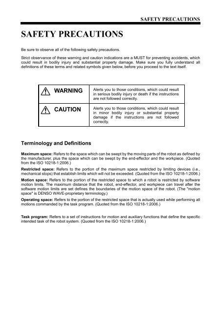
<strong>SAFETY</strong> <strong>PRECAUTIONS</strong><strong>SAFETY</strong> <strong>PRECAUTIONS</strong>Be sure to observe all of the following safety precautions.Strict observance of these warning and caution indications are a MUST for preventing accidents, whichcould result in bodily injury and substantial property damage. Make sure you fully understand alldefinitions of these terms and related symbols given below, before you proceed to the text itself.WARNINGCAUTIONAlerts you to those conditions, which could resultin serious bodily injury or death if the instructionsare not followed correctly.Alerts you to those conditions, which could resultin minor bodily injury or substantial propertydamage if the instructions are not followedcorrectly.Terminology and DefinitionsMaximum space: Refers to the space which can be swept by the moving parts of the robot as defined bythe manufacturer, plus the space which can be swept by the end-effector and the workpiece. (Quotedfrom the ISO 10218-1:2006.)Restricted space: Refers to the portion of the maximum space restricted by limiting devices (i.e.,mechanical stops) that establish limits which will not be exceeded. (Quoted from the ISO 10218-1:2006.)Motion space: Refers to the portion of the restricted space to which a robot is restricted by softwaremotion limits. The maximum distance that the robot, end-effector, and workpiece can travel after thesoftware motion limits are set defines the boundaries of the motion space of the robot. (The "motionspace" is <strong>DENSO</strong> WAVE-proprietary terminology.)Operating space: Refers to the portion of the restricted space that is actually used while performing allmotions commanded by the task program. (Quoted from the ISO 10218-1:2006.)Task program: Refers to a set of instructions for motion and auxiliary functions that define the specificintended task of the robot system. (Quoted from the ISO 10218-1:2006.)
1. Introduction This section provides safety precautions to be observed for therobot system.The installation shall be made by qualified personal and shouldconfirm to all national and local codes.Teaching, inspection, adjustment, and repair of the robot must becarried out by a trained worker who possesses the ability toperform these tasks safely.2. Warning LabelsThe robot unit and controller have warning labels. These labelsalert the user to the danger of the areas on which they arepasted. Be sure to observe the instructions printed on thoselabels.Warning labelInstructions printed on the labelRisk of injury.Never enter the restricted space.(Example: Location of labels)Label (1)For UL-Listed robot units onlyRisk of injury.This label alerts the user that pressingthe brake release switch could drop thearm.Label (2)Label (3)Label (4)Risk of electrical shock.Never open the controller cover whenthe power is on.Never touch the inside of the controllerfor at least 3 minutes even after turningthe power off and disconnecting thepower cable.Risk of injury.Be sure to perform lockout/tagoutbefore starting servicing.Turning the power ON when a person isinside the safety fence may move thearm, causing injuries.
<strong>SAFETY</strong> <strong>PRECAUTIONS</strong>3. Installation Precautions3.1 Insuring the properinstallation environment• For standard type andcleanroom type• For dust- & splash-prooftypeThe standard and cleanroom types have not been designed towithstand explosions, dust-proof, nor is it splash-proof.Therefore, it should not be installed in any environment where:(1) there are flammable gases or liquids,(2) there are any shavings from metal processing or otherconductive material flying about,(3) there are any acidic, alkaline or other corrosive material,(4) there is a mist,(5) there are any large-sized inverters, high output/highfrequency transmitters, large contactors, welders, or othersources of electrical noise.The dust- & splash-proof type has an IP54-equivalent structure,but it has not been designed to withstand explosions. (TheHM/HS-G-W and the wrist of the VM/VS-G-W are anIP65-equivalent dust- and splash-proof structure.)Note that the robot controller is not a dust- or splash-proofstructure. Therefore, when using the robot controller in anenvironment exposed to mist, put it in an optional protective box.The dust- & splash-proof type should not be installed in anyenvironment where:(1) there are any flammable gases or liquids,(2) there are any acidic, alkaline or other corrosive material,(3) there are any large-sized inverters, high output/highfrequency transmitters, large contactors, welders, or othersources of electrical noise,(4) it may likely be submerged in fluid,(5) there are any grinding or machining chips or shavings,(6) any machining oil not specified in this manual is in use, orNote: Yushiron Oil No. 4C (non-soluble) is specified.(7) there is sulfuric cutting or grinding oil mist.3.2 Service space The robot and peripheral equipment should be installed so thatsufficient service space is maintained for safe teaching,maintenance, and inspection.
3.3 Control devicesoutside the robot'srestricted spaceThe robot controller, teach pendant and mini-pendant should beinstalled outside the robot's restricted space and in a placewhere you can observe all of the robot’s movements and operatethe robot easily.In addition, the teach pendant and mini-pendant should beinstalled so that when someone is trying to stop the robot with theemergency stop switch, it is clear to which robot they areconnected, in order to prevent anyone from accidentally pressingthe emergency stop of the wrong robot.3.4 Positioning of gauges Pressure gauges, oil pressure gauges and other gauges shouldbe installed in an easy-to-check location.3.5 Protection of electricalwiring andhydraulic/pneumaticpipingIf there is any possibility of the electrical wiring orhydraulic/pneumatic piping being damaged, protect them with acover or similar item.3.6 Grounding resistance The protective grounding resistance of the robot power supplyshould not be more than 100Ω.3.7 Positioning ofemergency stopswitchesEmergency stop switches should be provided in a position wherethey can be reached easily should it be necessary to stop therobot immediately.(1) The emergency stop switches should be red.(2) Emergency stop switches should be designed so that theywill not be released after pressed, automatically ormistakenly by any other person.(3) Emergency stop switches should be separate from thepower switch.3.8 Positioning ofoperating statusindicatorsOperating status indicators should be positioned in such a waywhere workers can easily see whether the robot is on atemporary halt or on an emergency or abnormal stop.Note: The UL-Listed robot units have motor ON lamps on theirrobot arms.
<strong>SAFETY</strong> <strong>PRECAUTIONS</strong>3.9 Setting-up a safetyfenceA safety fence should be set up so that no one can easily enterthe robot's restricted space.(1) The fence should be constructed so that it cannot be easilymoved or removed.(2) The fence should be constructed so that it cannot be easilydamaged or deformed through external force.(3) Establish the exit/entrance to the fence. Construct the fenceso that no one can easily get past it by climbing over thefence.(4) The fence should be constructed to ensure that it is notpossible for hands or any other parts of the body to getthrough it.(5) Take any one of the following protections for the entrance/exit of the fence:1) Place a door, rope or chain across the entrance/exit ofthe fence, and fit it with an interlock that ensures theemergency stop device operates automatically if it isopened or removed.2) Post a warning notice at the entrance/exit of the fencestating "In operation--Entry forbidden" or "Work inprogress--Do not operate" and ensure that workersfollow these instructions at all times.When making a test run, before setting up the fence,place an overseer in a position outside the robot’srestricted space and one in which he/she can see all ofthe robot’s movements. The overseer should preventworkers from entering the robot's restricted space andbe devoted solely to that task.3.10 Setting the robot'smotion spaceThe area required for the robot to work is called the robot'soperating space.If the robot’s motion space is greater than the operating space, itis recommended that you set a smaller motion space to preventthe robot from interfering or disrupting other equipment.Refer to the INSTALLATION & MAINTENANCE GUIDE, Chapter2.
3.11 No robot modificationallowedNever modify the robot unit, robot controller, teach pendant orother devices.3.12 Cleaning of tools If your robot uses welding guns, paint spray nozzles, or otherend-effectors requiring cleaning, it is recommended that thecleaning process be carried out automatically.3.13 Lighting Sufficient illumination should be assured for safe robotoperation.3.14 Protection from objectsthrown by theend-effectorIf there is any risk of workers being injured in the event that theobject being held by the end-effector is dropped or thrown by theend-effector, consider the size, weight, temperature andchemical nature of the object and take appropriate safeguards toensure safety.3.15 Affixing the warninglabelPlace the warning label packagedwith the robot on the exit/entranceof the safety fence or in a positionwhere it is easy to see.3.16 Posting the movingdirections of all axes3.17 Changing theconfigurationPost a notice showing axes names and moving directions in avisible location on the robot unit. The posted moving directionsshould match the actual directions.No posting or wrong direction posting may result in bodily injuriesor property damages due to incorrect operation.When the components of the robot system or optional devices(including hardware and software) have been changed or added,carry out necessary tests or inspections of safety functions.
<strong>SAFETY</strong> <strong>PRECAUTIONS</strong>4. Precautionswhile Robot isRunningWarningTouching the robot while it is inoperation can lead to seriousinjury. Please ensure the followingconditions aremaintained and that thecautions listed from Section4.1 and onwards are followedwhen any work is beingperformed.1) Do not enter the robot's restricted space when the robotis in operation or when the motor power is on.2) As a precaution against malfunction, ensure that anemergency stop device is activated to cut the power tothe robot motor upon entry into the robot's restrictedspace.3) When it is necessary to enter the robot's restricted spaceto perform teaching or maintenance work while the robotis running, ensure that the steps described in Section 4.3"Ensuring safety of workers performing jobs within therobot's restricted space" are taken.4.1 Creation of workingregulations andassuring workeradherenceWhen entering the robot’s restricted space to perform teachingor maintenance inspections, set "working regulations" for thefollowing items and ensure workers adhere to them.(1) Operating procedures required to run the robot.(2) Robot speed when performing teaching.(3) Signaling methods to be used when more than one worker isto perform work.(4) Steps that must be taken by the worker in the event of amalfunction, according to the contents of the malfunction.(5) The necessary steps for checking release and safety of themalfunction status, in order to restart the robot after robotmovement has been stopped due to activation of theemergency stop device(6) Apart from the above, any steps below necessary to preventdanger from unexpected robot movement or malfunction ofthe robot.1) Display of the control panel (See Section 4.2 on the nextpage.)2) Assuring the safety of workers performing jobs within therobot's restricted space (See Section 4.3 on the nextpage.)3) Maintaining worker position and stancePosition and stance that enables the worker to confirmnormal robot operation and to take immediate refuge if amalfunction occurs.
4) Implementation of measures for noise prevention5) Signaling methods for workers of related equipment6) Types of malfunctions and how to distinguish themPlease ensure "working regulations" are appropriate to the robottype, the place of installation and to the content of the work.Be sure to consult the opinions of related workers, engineers atthe equipment manufacturer and that of a labor safety consultantwhen creating these "working regulations".4.2 Display of operationpanelTo prevent anyone other than the worker from accessing the startswitch or the changeover switch by accident during operation,display something to indicate it is in operation on the operationpanel or teach pendant. Take any other steps as appropriate,such as locking the cover.4.3 Ensuring safety ofworkers performingjobs within the robot'srestricted space4.4 Inspections beforecommencing worksuch as teachingWhen performing jobs within the robot’s restricted space, takeany of the following steps to ensure that robot operation can bestopped immediately upon a malfunction.(1) Ensure an overseer is placed in a position outside therobot’s restricted space and one in which he/she can see allrobot movements, and that he/she is devoted solely to thattask. An emergency stop device should be activatedimmediately upon a malfunction. Do not permit anyone other than the worker engaged forthat job to enter the robot’s restricted space.(2) Ensure a worker within the robot's restricted space carriesthe portable emergency stop switch so he/she can press it(the emergency button on the teach pendant) immediately ifit should be necessary to do so.Before starting work such as teaching, inspect the followingitems, carry out any repairs immediately upon detection of amalfunction and perform any other necessary measures.(1) Check for any damage to the sheath or cover of the externalwiring or to the external devices.(2) Check that the robot is functioning normally or not (anyunusual noise or vibration during operation).(3) Check the functioning of the emergency stop device.(4) Check there is no leakage of air or oil from any pipes.(5) Check there are no obstructive objects in or near the robot’srestricted space.(6) Ensure a worker engaged in the job carries the emergencystop switch (the emergency stop button on the teachpendant and mini-pendant) such that he/she can press itimmediately.(7) Do not permit anyone other than the worker engaged in thejob to enter the safety fence.
<strong>SAFETY</strong> <strong>PRECAUTIONS</strong>4.5 Release of residual airpressureBefore disassembling or replacing pneumatic parts, first releaseany residual air pressure in the drive cylinder.4.6 Precautions for testrunsWhenever possible, have the worker stay outside of the robot'srestricted space when performing test runs.Carry out an initial test and periodic inspections to ensure thatprotective measures are in effect. Protective measures includethe emergency stop switch, signals linked to the safety fence(automatic enable signal and protective stop signal), andmechanical stops.4.7 Precautions forautomatic operation(1) At start-upBefore selecting the automatic mode, ensure that all safetyprotective functions are working.Stay out of the safeguarded space with a safety fence whenstarting the robot; in particular, take extra caution in Internalautomatic operation.Before starting the robot, check the following items as wellas setting the signals to be used and perform signalingpractice with all related workers.1) Check that there is no one inside the safeguarded space(with a safety fence).2) Check that the teach pendant and tools are in theirdesignated places.3) Check that no lamps indicating a malfunction on therobot or related equipment are lit.(2) Check that the display lamp indicating automatic operationis lit during automatic operation.(3) Steps to be taken when a malfunction occursStop the robot's operation by activating the emergency stopdevice when it is necessary to enter the safeguarded spacewith a safety fence to perform emergency maintenance inthe case of malfunction of the robots or related equipment.Take any necessary steps such as posting a notice on thestart switch to indicate work is in progress to prevent anyonefrom accessing the robot.4.8 Precautions in repairs (1) Do not perform repairs outside of the designated range.(2) Under no circumstances should the interlock mechanism beremoved.(3) When opening the robot controller's cover for batteryreplacement or any other reasons, always turn the robotcontroller power off and disconnect the power cable.(4) Use only spare tools specified in this manual.
4.9 Action duringemergencies andmalfunctions4.10 On mechanicalstoppersDecide on actions to be taken by personnel when emergenciesor malfunctions occur, and train them in advance.In addition, when the motor power is cut off in emergencies, therobot can be moved by hand after releasing the brake.Regarding release of the brake, see the INSTALLATION &MAINTENANCE GUIDE for each robot.When the robot has collided with a mechanical stopper, contactus for inspection and repairs before using the robot because therobot may be damaged.5. Daily and PeriodicalInspections(1) Be sure to perform daily and periodical inspections. Beforestarting jobs, always check that there is no problem with therobot and related equipment. If any problems are found,take any necessary measures to correct them.(2) When carrying out periodical inspections or any repairs,maintain records and keep them for at least 3 years.6. Managing robot data (1) After finishing teaching or making any changes, always backup data such as programs with off-line software(WINCAPSIII). Making back-ups will help you recover if datastored in the robot controller is lost because the life of theback-up battery has expired.(2) Clearly indicate for which robot the back-ups were made toprevent the data from being loaded into the wrong robotcontroller.7. Safety Codes The safety standards relating to robot systems are listed below.As well as observing the safety precautions given in this manual,ensure compliance with all local and national safety andelectrical codes for the installation and operation of the robotsystem.StandardsANSI/RIA R15.06-1999ANSI/UL1740: 2007CAN/CSA Z434-03ISO10218-1: 2006NFPA79: 2007TitleIndustrial Robots and Robot Systems--Safety RequirementsSafety for Robots and Robotic EquipmentIndustrial Robots and Robot Systems--General Safety RequirementsRobots for industrial environments--Safety requirements--Part 1: RobotElectrical Standard for Industrial Machinery8. Battery Recycling <strong>DENSO</strong> Robot uses lithium batteries.Discard batteries according to your local and national recyclinglaw.
お 問 い 合 わせ 先Contact Us日 本( 株 )デンソーウェーブFA 技 術 サポートセンター愛 知 県 知 多 郡 阿 久 比 町 大 字 草 木 字 芳 池 1 番 地[( 株 )デンソー 阿 久 比 製 作 所 内 ]TEL 0569-49-1591Asia, OceaniaNorth AmericaEurope<strong>DENSO</strong> WAVE INCORPORATED1, Yoshiike, Kusagi, Agui-cho, Chita-gun,Aichi 470-2297, JapanTEL +81-569-49-5020<strong>DENSO</strong> SALES CALIFORNIA, INC.3900 Via Oro Avenue, Long Beach, California 90810, U.S.ATEL +1-888-476-2689<strong>DENSO</strong> EUROPE B. V. <strong>Robotics</strong> DepartmentWaldeckerstrasse 9 D-64546 Moerfelden-Walldorf, GermanyTEL +49 (0) 6105-27 35 150