An Embedded Real-Time System for Autonomous Flight Control
An Embedded Real-Time System for Autonomous Flight Control
An Embedded Real-Time System for Autonomous Flight Control

Create successful ePaper yourself
Turn your PDF publications into a flip-book with our unique Google optimized e-Paper software.
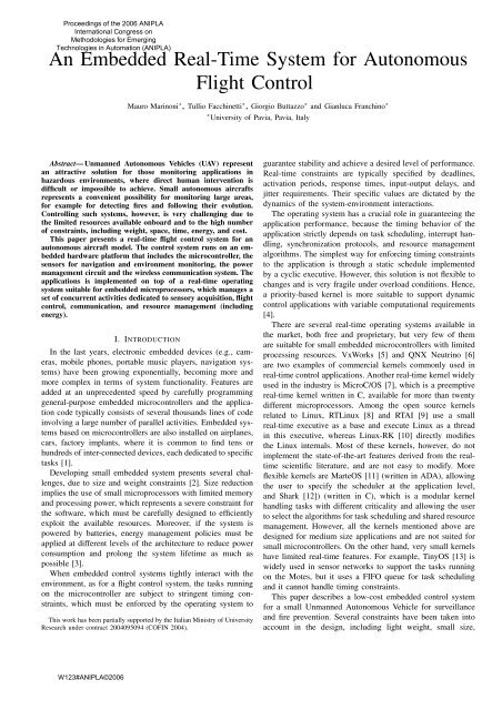
Task Period [ms] VariableGPS 1000.0 YesAccelerometer 12.5 NoInclinometer 200.0 YesGyroscopes 12.5 No<strong>Control</strong> 12.5 NoTemperature 1000.0 YesPower 1000.0 YesCommunication 100.0 YesTABLE IIACTIVATION PERIODS OF THE APPLICATION TASKS.Fig. 4.to µ CI2C or SPImonitorPower consumption monitoring system.loadvalues (from GPS and inclinometer) to periodically reset thedrift on relative measurements [19].Finally, the system also includes other sensors <strong>for</strong> missionspecific purposes. Since the main goal of the system is todetect and monitor fires, the aircraft is equipped with aninfrared camera to detect fire sources in <strong>for</strong>ests and woods,and a temperature sensor to measure the air temperature inspecific locations in case of extended fires.B. Actuators controlThe actuators consist of two servomotors <strong>for</strong> the flaps anda DC motor <strong>for</strong> the throttle. All the motors are controlledthrough Pulse Width Modulation (PWM) signals. While <strong>for</strong>servomotors the PWM signals define the motor shaft angularposition, the throttle PWM signal controls the motor speed.During manual operations the PWM signals are generatedby the receiver based on the commands received from theremote control. While the aircraft is flying autonomously,the signals are generated by dedicated output ports on themicrocontroller. The selection between the two PWM signalsources is per<strong>for</strong>med by the custom board showed in Figure2 and described in Section II-D.C. <strong>Real</strong>-time issuesThe control application consists of a set of periodic real-timetasks interacting through shared memory buffers protected bymutually exclusive semaphores. A simplified version of theStack Resource [18] available in the Erika Enterprise kernelis used to access the critical sections in a predictable fashion,preventing unbounded priority inversion [20] and allowing anoff-line guarantee of the application.Application tasks are periodically activated by the kernelto per<strong>for</strong>m sensory acquisition and control. Tasks periods areshown in Table III-C and defined based on the specific sensorfeature and on control considerations. Note that some periodsare fixed and others may change during the flight dependingon specific situations. For example, the sampling rate of the“fast” navigation sensors is related to the one of the controltask, which is fixed and defined by the sampling frequencyused in the control algorithm. On the other hand, the periods ofremaining tasks have no such a constraint and can be changedto balance the microcontroller load (and there<strong>for</strong>e its speedand power absorption, see Section IV-A) with the accuracy ofthe sensed in<strong>for</strong>mation.IV. POWER MANAGEMENTThe power management strategy is per<strong>for</strong>med by the microcontrollerin different ways, depending on the energymanagementfeatures available on the peripherals. Hardwareand software components have been integrated to meet severalgoals: onboard sensory data processing, real-time computation,and communication features, while achieving low power consumption.To achieve significant energy saving, power-awarestrategies are adopted within every system module and arecoordinated at the operating system level [21].All the aircraft onboard systems, including motors, sensorsand embedded control board, are powered by batteries. Thereare 2 different battery packs. All the devices required <strong>for</strong>manually controlled operation are grouped and powered byone battery pack; they include the receiver, the manual/autoselection custom board, the throttle motor and flaps servomotors.The second battery pack feeds sensors and control board.The battery charge level is monitored by the microcontrollerto adapt the energy management strategy. Figure 4 shows thecustom circuit designed to monitor the charge level <strong>for</strong> eachbattery pack. It is based on the Texas Instruments’s bq27200chip, expressly designed <strong>for</strong> monitoring Li-Ion and Li-Polbatteries.A. Dynamic voltage schedulingA widely adopted method to obtain power-aware systems isDynamic Voltage Scheduling (DVS) [22]. In DVS techniques,the processor voltage supply can be decreased to save energy,since the power absorbtion depends from the third power ofthe input voltage supply level. However, decreasing the supplyvoltage also limits the maximum clock frequency, hence theprocessor speed. There<strong>for</strong>e, proper strategies must be adoptedto minimize energy consumption under real-time constraints.Power-aware scheduling algorithms <strong>for</strong> a discrete set ofclock frequencies are implemented on top of the dsPICbasedplat<strong>for</strong>m, exploiting the DVS features described inSection II-A. The simplest strategy exploits the processor sleepstate when there is no work to be executed. In this case,the processor is completely disabled, and it is resumed bythe system timer <strong>for</strong> a task activation or after an interruptgeneration from a peripheral device. The sleep state is alsoconsidered as an actual operating mode, and the correspondingzero speed is included in the set of available speed levels.A simple approach <strong>for</strong> power-aware real-time schedulinguses a fixed processor clock speed, computed off-line toguarantee system feasibility [22]. However, due to the limited
Module I on I off V in CtrlAccelerometer 750 µA 10 µA 3.3V YesGPS 170 mA 10 µA 3.3V NoTemperature 28-550 µA 1 µA 3.3V YesTX/RX 35-80 mA 5 µA 3.3V YesMMC 25-60 mA 150 µA 3.3V YesGyroscope [x3] 6 mA 5.0V NoPressure [x2] 10 mA 5.0V NoTX A/V [x2] 60 mA 11.2V NoCamera IR 500 mA 5.0V NoCamera 40 mA 5.0V NoTABLE IIIPOWER-RELATED PROPERTIES OF ONBOARD PERIPHERAL DEVICES.has to be consumed. Power-aware communication protocolshave also to take into account the overhearing, occurring whena node picks up packets that are not sent to it, and the protocoloverhead, due to control packets used in several protocolsto manage the communication (e.g., RTS/CTS packets in theIEEE 802.11 [27]). Transmission power control [28], [29] isalso useful <strong>for</strong> saving energy while guaranteeing network connectivity,managing nodes density and allowing spatial reuseof radio channels. Moreover, minimizing transmission powercan also indirectly reduce energy consumption by reducing thechannel contention and collision between transmitting nodes.number of available discrete frequencies <strong>for</strong> the system clock,this solution may cause a waste of energy, because the optimalclock speed must be rounded to the closest higher speed.Better results can be achieved by alternating two discrete clockfrequencies, as a PWM signal, to obtain the optimal clockvalue [23]. Other approaches calculate different speeds <strong>for</strong>each task and set the system clock to the appropriate valuewhen a context switch occurs [24]. A combination of the twomethods is also possible: the off-line calculation of the optimalworking speed is integrated by on-line reclamation techniquesto further reduce the processor speed and exploit the unusedcomputation time [25], [26].B. Peripheral I/OSignificant energy saving is achieved by a careful managementof peripheral devices. The MCU can turn off each singledevice in different operating modes, where each device/modepair is characterized by known energy requirements. Table IV-B shows the power-related properties of peripheral devices.For each device, Table IV-B reports the current absorbtion inboth enabled (I on ) and disabled (I off ) mode, the power supplyvoltage (V in ); the Ctrl value indicates whether it is possibleto turn the device in power-saving mode through a dedicateddigital line directly from the microcontroller. A digital powercontrolline allows resuming the device faster, without theneed of dedicated circuits. Notice that, while the I off valueis available <strong>for</strong> devices with digital power control only, theGPS module represents an exception, due to its peculiar powermanagement, which needs a dedicated (but no digital) line.The absorption values suggest that, since power consumptionranges from 1 up to 4 orders of magnitudes betweenenabled and disabled modes, paying attention to the peripheraldevices power states may lead to dramatic power saving.Since a relevant amount of energy is consumed <strong>for</strong> wirelesscommunication by the radio module, a careful power-awaredesign of the communication protocol allows considerableenergy saving (see the TX/RX field in Table IV-B). There areseveral issues that can be considered <strong>for</strong> reducing the energyconsumption in a radio module. A source of energy wasting isidle listening, which is due to the energy required <strong>for</strong> listeningto the channel possible incoming messages. A second sourceof wasting is due to packet collisions: when two or moremessages are sent at the same time by different nodes, packetcollisions may be experienced, thus producing corrupted packets;since such packets have to be re-transmitted, extra-energyC. Kernel supportThe power management system, which is responsible <strong>for</strong>selecting the most appropriate power states both <strong>for</strong> the CPUand the peripheral devices, aims at providing a uni<strong>for</strong>m programminginterface, while achieving high efficiency to reducethe system overhead. Its main features allow:• to get the maximum power level allowed by the system<strong>for</strong> a specific device;• to get the minimum power level required <strong>for</strong> the operatingsystem consistency;• to get the power level actually used by a device;• to get the power level required by a running, ready oridle task;• to set the power level <strong>for</strong> a device while the task isrunning; the actual device power level will be decidedby the power manager based on all task requirements;• to set/get the power level required by the task while it isnot running;V. CONCLUSIONS AND FUTURE WORKThis paper describes a real-time control system <strong>for</strong> theautonomous flight of model aircrafts. The description focuseson all the relevant architecture components. The hardwareplat<strong>for</strong>m includes the microcontroller, communication system,sensors <strong>for</strong> navigation and environment monitoring, and powermanagement circuits. The control program running on themicrocontroller is implemented on top of a real-time kernelto guarantee the timing constraints of application tasks. Thesoftware also controls the power consumption of peripheraldevices and the microcontroller itself, implements the communicationprotocol and drives the motors to follow the desiredtrajectory.The proposed architecture has been installed on a aircraftmodel <strong>for</strong> fire monitoring. The specific application justifies theinstallation of special sensors <strong>for</strong> fire detection and monitoring:infrared camera and temperature sensors are added to the sensorsrequired by the navigation system. The plat<strong>for</strong>m is flexibleenough to allow changing the application specific sensors toadapt the aircraft to other purposes, such as surveillance ordifferent monitoring activities.REFERENCES[1] J. Turley, “<strong>Embedded</strong> processors,” ExtremeTech,http://www.extremetech.com, January 2002.
[2] H. Gill, “Challenges <strong>for</strong> critical embedded systems,” in Proceedings ofthe 10th IEEE International Workshop on Object-Oriented <strong>Real</strong>-<strong>Time</strong>Dependable <strong>System</strong>s (WORDS), February 2005, pp. 7–9.[3] R. Melhem, N. AbouGhazaleh, H. Aydin, and D. Mossé, Power ManagementPoints in Power-Aware <strong>Real</strong>-<strong>Time</strong> <strong>System</strong>s. R. Graybill andR. Melhem (editors), Plenum/Kluwer Publishers, 2002.[4] G. C. Buttazzo, Hard <strong>Real</strong>-time Computing <strong>System</strong>s: PredictableScheduling Algorithms amd Applications, 2nd ed. Springer, 2005.[5] “VxWorks <strong>Real</strong>-<strong>Time</strong> OS,” wind River Corp., URL:http://www.windriver.com/vxworks.[6] “QNX Neutrino RTOS,” qNX Software <strong>System</strong>s, URL:http://www.qnx.com.[7] J. J. Labrosse, Micro C/OS-II: The <strong>Real</strong>-<strong>Time</strong> Kernel. CMP Books,2002.[8] “RTLinux RTOS,” fSMLabs Inc., URL: http://www.fsmlabs.com.[9] E. Bianchi, L. Dozio, G. L. Ghiringhelli, and P. Mantegazza, “Complexcontrol systems, applications of DIAPM-RTAI at DIAPM,” in <strong>Real</strong>timeLinux Workshop, 1999.[10] S. Oikawa and R. Rajkumar, “Portable RK: A portable resource kernel<strong>for</strong> guaranteed and en<strong>for</strong>ced timing behavior,” in Proc. of the IEEE<strong>Real</strong>-<strong>Time</strong> Technology and Applications Symp., June 1999.[11] M. A. Rivas and M. G. Harbour, “MaRTE OS: <strong>An</strong> ada kernel <strong>for</strong>real-time embedded applications,” in Proc. of the 6th InternationalConference on Reliable Software Technologies (Ada-Europe’2001), May2001.[12] P. Gai and G. Buttazzo, “<strong>An</strong> open source real-time kernel <strong>for</strong> controlapplications,” in Proceedings of the 47th Italian Conference of FactoryAutomation (ANIPLA 2003), November 2003, pp. 21–22.[13] D. Gay, P. Levis, and D. Culler, “oftware design patterns <strong>for</strong> tinyos,” inProc. of the ACM SIGPLAN/SIGBED 2005 Conference on Languages,Compilers, and Tools <strong>for</strong> <strong>Embedded</strong> <strong>System</strong>s (LCTES’05), June 2005.[14] “Mp202 g autopilot,” micropilot Corp., URL:http://www.micropilot.com.[15] “ERIKA Enterprise RTOS,” evidence Srl, URL:http://www.evidence.eu.com.[16] dsPIC30F family reference manual (DS70046C), 2004, microchip TechnologyInc., URL: http://www.microchip.com.[17] C. L. Liu and J. W. Layland, “Scheduling algorithms <strong>for</strong> multiprogrammingin a hard real-time environment,” Journal of the ACM, pp. 40–61,1973.[18] T. P. Baker, “A stack-based resource allocation policy <strong>for</strong> real-timeprocesses,” in Proc. of the IEEE <strong>Real</strong>-<strong>Time</strong> <strong>System</strong>s Symp., December1990, pp. 191–200.[19] D. Gebre-Egziabher, R. C. Hayward, and J. D. Powell, “A low costgps/inertial attitude heading reference system (ahrs) <strong>for</strong> general aviationapplications,” in Proceedings of the IEEE Position Location andNavigation Symposium (PLANS), April 1998.[20] L. Sha, R. Rajkumar, and J. P. Lehoczky, “Priority inheritance protocols:<strong>An</strong> approach to real-time synchronization,” IEEE Trans. on Computers,vol. 39, no. 9, pp. 1175–1185, September 1990.[21] M. Marinoni, G. Buttazzo, T. Facchinetti, and G. Franchino, “Kernelsupport <strong>for</strong> energy management in wireless mobile ad-hoc networks,” inProc. of the Workshop on Operating <strong>System</strong>s Plat<strong>for</strong>ms <strong>for</strong> <strong>Embedded</strong><strong>Real</strong>-<strong>Time</strong> applications (OSPERT’05), July 2005.[22] P. Pillai and K. Shin, “<strong>Real</strong>-time dynamic voltage scaling <strong>for</strong> low-powerembedded operating systems,” in Operating <strong>System</strong>s Review (ACM),18th ACM Symposium on Operating <strong>System</strong>s Principles (SOSP), October2002, pp. 89–102.[23] E. Bini, G. C. Buttazzo, and G. Lipari, “Speed modulation in energyawarereal-time systems,” in IEEE Proceedings of the Euromicro Conferenceon <strong>Real</strong>-<strong>Time</strong> <strong>System</strong>s, July 2005.[24] P. M. Alvarez, E. Levner, and D. Mossé, “Adaptive scheduling server<strong>for</strong> power-aware real-time tasks,” ACM Transactions on <strong>Embedded</strong>Computing <strong>System</strong>s, vol. 3, no. 2, pp. 284–306, May 2004.[25] H. Aydin, R. Melhem, D. Mossé, and P. M. Alvarez, “Power-awarescheduling <strong>for</strong> periodic real-time tasks,” IEEE Transactions on Computers,vol. 53, no. 5, pp. 584–600, May 2004.[26] W. Kim, D. Shin, H. Yun, J. Kim, and S. Min, “Per<strong>for</strong>mance comparisionof dynamic voltage scaling algorithms <strong>for</strong> hard real-time systems,” inProc. 8th IEEE <strong>Real</strong>-<strong>Time</strong> and <strong>Embedded</strong> Technology and ApplicationsSymp., San Jose, Cali<strong>for</strong>nia, September 2002, pp. 219–228.[27] Wireless LAN Medium Access <strong>Control</strong> (MAC) and Physical Layer (PHY)Specification, iEEE 1999.[28] J. Heidemann and W. Ye, Energy Conservation in Sensor Networksat the Link and Network Layers. Nirupama Bulusu and Sanjay Jha(editors), 2005, technical Report ISI-TR-2004-599, USC/In<strong>for</strong>mationSciences Institute, 2004.[29] R. Ramanathan and R. Rosales-Hain, “Topology control of multihopwireless networks using transmit power adjustment,” in Proc. of theIEEE Infocom, March 2000.