6. Carbon Steel Pipe & Fittings and Tube - Atlas Steels
6. Carbon Steel Pipe & Fittings and Tube - Atlas Steels
6. Carbon Steel Pipe & Fittings and Tube - Atlas Steels

Create successful ePaper yourself
Turn your PDF publications into a flip-book with our unique Google optimized e-Paper software.
<strong>Carbon</strong> <strong>Steel</strong> <strong>Pipe</strong> <strong>Fittings</strong>,Flanges <strong>and</strong> <strong>Tube</strong><strong>Carbon</strong> <strong>Steel</strong> <strong>Pipe</strong>6<strong>Fittings</strong>, Flanges <strong>and</strong> <strong>Tube</strong>Photography courtesy of Darwin LNG <strong>and</strong> <strong>Atlas</strong> <strong>Steel</strong>s.
www.atlassteels.com.au
Buttwelding Specification ASTM A234M<strong>Fittings</strong> (Moderate <strong>and</strong> High Temperature Service)Welded <strong>and</strong> Seamless <strong>Carbon</strong> <strong>and</strong> Alloy<strong>Steel</strong> <strong>Pipe</strong> <strong>Fittings</strong>ASTM A420M(Low Temperature Service)Welded <strong>and</strong> Seamless <strong>Carbon</strong> <strong>and</strong> Alloy<strong>Steel</strong> <strong>Pipe</strong> <strong>Fittings</strong>Dimensions ASME B1<strong>6.</strong>9Product Elbows, Reducing Elbows, Returns, Tees,Crosses, Reducers, Stub Ends, CapsGrade WPB, Refer st<strong>and</strong>ard for othersFlanges Specification ASTM A105M<strong>Carbon</strong> <strong>Steel</strong> Forgings for Piping ApplicationsDimensions ASME B1<strong>6.</strong>5Product Weld Neck, Slip-on, Blind FlangesFace Plain, Raised FaceBore <strong>Pipe</strong> ScheduleClass 150, 300,400, 600, 900, 1500, 2500 (to600mm only)Grade <strong>Carbon</strong> <strong>Steel</strong>Specification AS 2129Flanges for <strong>Pipe</strong>s, Valves <strong>and</strong> <strong>Fittings</strong>Dimensions AS 2129“Table” flanges pressure – temperatureratings, materials <strong>and</strong> dimensionsApplication Slip-on, Blind “Table” FlangesFace PlainBore To suit <strong>Pipe</strong> & <strong>Tube</strong> ODTable D, E, F, <strong>and</strong> H1S6Specifications • <strong>Carbon</strong> <strong>Steel</strong> <strong>Pipe</strong>, Buttwelding <strong>Fittings</strong>, FlangesLinepipe Specification ASTM A53/A53MDimensions ASME B3<strong>6.</strong>10MProduct Welded <strong>and</strong> Seamless <strong>Steel</strong> <strong>Pipe</strong>Grades A, BSpecification ASTM A106Dimensions ASME B3<strong>6.</strong>10MProduct Seamless <strong>Carbon</strong> <strong>Steel</strong> <strong>Pipe</strong> for High TemperatureServiceGrades A,B,CSpecification ASTM A335/A335MDimensions ASME B3<strong>6.</strong>10MProduct Seamless Ferritic Alloy-<strong>Steel</strong> <strong>Pipe</strong> for HighTemperature ServiceGrades Refer St<strong>and</strong>ard for gradesSpecification ASTM A333/A333MDimensions ASME B3<strong>6.</strong>10MProduct Seamless & Welded <strong>Carbon</strong> <strong>and</strong> Alloy <strong>Steel</strong> <strong>Pipe</strong> forLow Temperature ServiceGrade Refer St<strong>and</strong>ard for gradesSpecification API 5L/ISO 3183Dimensions ASME B3<strong>6.</strong>10M, API 5LProduct Seamless & Welded for Line <strong>Pipe</strong>Grades A, B, X42, X52, X60, Refer API 5L specification forothersStructural <strong>Steel</strong> Specification AS 1163Dimensions AS 1163Product Structural <strong>Steel</strong> Hollow SectionsGrade C3501S4Printed July 2010www.atlassteels.com.au
2S6<strong>Carbon</strong> <strong>Steel</strong> <strong>Pipe</strong> • DimensionsStructural <strong>Steel</strong> Hollow Sections to AS1163Welded & Seamless <strong>Carbon</strong> <strong>Steel</strong> <strong>Pipe</strong> to ASME B3<strong>6.</strong>10MODNominal sizePrinted July 2010Chart All dimensions of Commom are Stainless mm <strong>Steel</strong> <strong>Pipe</strong> GradesGrade C350Chemical Schedule Analysis (%) SpecifiedWall Thickness in mmPrinted July 2010mmDN NPS4.8 5.5 <strong>6.</strong>0 <strong>6.</strong>4 7.1 8.2 9.3 9.5 12.710 20 30 40 Std 60 80 XS 100 120 140 160 XXS6 1 /8 10.3 1.24 1.45 1.73 1.73 2.41 2.418 1 /4 13.7 1.65 1.85 2.24 2.24 3.02 3.0210 3 /8 17.1 1.65 1.85 2.31 2.31 3.20 3.2015 1 /2 21.3 2.11 2.41 2.77 2.77 3.73 3.73 4.78 7.4720 3 /4 2<strong>6.</strong>7 2.11 2.41 2.87 2.87 3.91 5.56 7.8225 1 33.4 2.77 2.90 3.38 3.38 4.55 4.55 <strong>6.</strong>35 9.0932 1 1 /4 42.2 2.77 2.97 3.56 3.56 4.85 4.85 <strong>6.</strong>35 9.7040 1 1 /2 48.3 2.77 3.18 3.68 3.68 5.08 5.08 7.14 10.1550 2 60.3 2.77 3.18 3.91 3.91 5.54 5.54 8.74 11.0765 2 1 /2 73.0 3.05 4.78 5.16 5.16 7.01 7.01 9.53 14.0280 3 88.9 3.05 4.78 5.49 5.49 7.62 7.62 11.13 15.24 90 3 1 /2 101.6 3.05 4.78 5.74 5.74 8.08 8.08100 4 114.3 3.05 4.78 <strong>6.</strong>02 <strong>6.</strong>02 8.56 8.56 11.13 13.49 17.12 125 5 141.3 3.40 <strong>6.</strong>55 <strong>6.</strong>55 9.53 9.53 12.70 15.88 19.05150 6 168.3 3.40 7.11 7.11 10.97 10.97 14.27 18.26 21.95 200 8 219.1 3.76 <strong>6.</strong>35 7.04 8.18 8.18 10.31 12.70 12.70 15.09 18.26 20.62 23.01 22.23 250 10 273.0 4.19 <strong>6.</strong>35 7.80 9.27 9.27 12.70 15.09 12.70 18.26 21.44 25.40 28.58 25.40 300 12 323.8 4.57 <strong>6.</strong>35 8.38 10.31 9.53 14.27 17.48 12.70 21.44 25.40 28.58 33.32 25.40 350 14 355.6 <strong>6.</strong>35 7.92 9.53 11.13 9.53 15.09 19.05 12.70 23.83 27.79 31.75 35.71 400 16 40<strong>6.</strong>4 <strong>6.</strong>35 7.92 9.53 12.70 9.53 1<strong>6.</strong>66 21.44 12.70 2<strong>6.</strong>19 30.96 3<strong>6.</strong>53 40.49 450 18 457 <strong>6.</strong>35 7.92 11.13 14.27 9.53 19.05 23.83 12.70 29.36 34.93 39.67 45.24 500 20 508 <strong>6.</strong>35 9.53 12.70 15.09 9.53 20.62 2<strong>6.</strong>19 12.70 32.54 38.10 44.45 50.01550 22 559 <strong>6.</strong>35 9.53 12.70 9.53 22.23 28.58 12.70 34.93 41.28 47.63 53.98600 24 610 <strong>6.</strong>35 9.53 14.27 17.48 9.53 24.61 30.96 12.70 38.89 4<strong>6.</strong>02 52.37 59.54650 26 660 7.92 12.70 9.53 12.70700 28 711 7.92 12.70 15.88 9.53 12.70750 30 762 7.92 12.70 15.88 9.53 12.70800 32 813 7.92 12.70 15.88 17.48 9.53 12.70850 34 864 7.92 12.70 15.88 17.48 9.53 12.70900 36 914 7.92 12.70 15.88 19.05 9.53 12.70950 38 965 9.53 12.701000 40 1016 9.53 12.701050 42 1067 9.53 12.701100 44 1118 9.53 12.701150 46 1168 9.53 12.701200 48 1219 9.53 12.70Note 1: For dimensional tolerances refer to ASMT A53 or A106MEquivalent sizes shown in API Specification 5Lwww.atlassteels.com.auwww.atlassteels.com.au
<strong>Carbon</strong> <strong>Steel</strong> <strong>Pipe</strong> • WeightsStructural <strong>Steel</strong> Hollow Sections to AS1163Welded & Seamless <strong>Carbon</strong> <strong>Steel</strong> <strong>Pipe</strong> to ASME B3<strong>6.</strong>10MODNominal sizePrinted July 2010Chart All weights of Commom are in Stainless kg/m <strong>Steel</strong> <strong>Pipe</strong> GradesAll weights are in kg/mChemical Schedule Analysis (%) SpecifiedWall Thickness in mmPrinted July 2010mmDN NPS4.8 5.5 <strong>6.</strong>0 <strong>6.</strong>4 7.1 8.2 9.3 9.5 12.710 20 30 40 Std 60 80 XS 100 120 140 160 XXS6 1 /8 10.3 0.28 0.32 0.37 0.37 0.47 0.478 1 /4 13.7 0.49 0.54 0.63 0.63 0.80 0.8010 3 /8 17.1 0.63 0.70 0.84 0.84 1.10 1.1015 1 /2 21.3 1.00 1.12 1.27 1.27 1.62 1.62 1.95 2.5520 3 /4 2<strong>6.</strong>7 1.28 1.44 1.69 1.69 2.20 2.20 2.90 3.6425 1 33.4 2.09 2.18 2.50 2.50 3.24 3.24 4.24 5.4532 1 1 /4 42.2 2.70 2.87 3.39 3.39 4.47 4.47 5.61 7.7740 1 1 /2 48.3 3.11 3.53 4.05 4.05 5.41 5.41 7.25 9.5650 2 60.3 3.93 4.48 5.44 5.44 7.48 7.48 11.11 13.4465 2 1 /2 73.0 5.26 8.04 8.63 8.63 11.41 11.41 14.92 20.3980 3 88.9 <strong>6.</strong>45 9.92 11.29 11.29 15.27 15.27 21.35 27.67 10.0 11.390 3 1 /2 101.6 7.40 11.41 13.57 13.57 18.63 18.63100 4 114.3 8.36 12.91 1<strong>6.</strong>07 1<strong>6.</strong>07 22.32 22.32 28.32 33.54 41.03 13.0 1<strong>6.</strong>0125 5 141.3 11.57 21.77 21.77 30.97 30.97 40.28 49.11 57.43150 6 168.3 13.84 28.26 28.26 42.56 42.56 54.20 67.56 79.22 19.4 25.6 28.2200 8 219.1 19.96 33.31 3<strong>6.</strong>81 42.55 42.55 53.08 64.64 64.64 75.92 90.44 100.92 111.27 107.92 25.4 33.6 42.6 64.6250 10 273.0 27.78 41.77 51.03 60.31 60.31 81.55 9<strong>6.</strong>01 81.55 114.75 133.06 155.15 172.33 155.15 31.8 42.1 60.5 81.5300 12 323.8 3<strong>6.</strong>00 49.73 65.20 79.73 73.88 108.96 132.08 97.43 159.91 18<strong>6.</strong>97 208.14 238.76 18<strong>6.</strong>97 50.1 73.7 97.5350 14 355.6 54.69 67.90 81.33 94.55 81.33 12<strong>6.</strong>71 158.10 107.39 194.96 224.65 253.56 281.70 55.1 81.1 107.0400 16 40<strong>6.</strong>4 62.64 77.83 93.27 123.30 93.27 160.12 203.53 123.30 245.56 28<strong>6.</strong>64 333.19 365.35 63.1 93.0 123.0450 18 457 70.57 87.71 122.38 155.80 105.16 205.74 254.55 139.15 309.62 363.56 408.26 459.37 71.1 105.0 139.0500 20 508 78.55 117.15 155.12 183.42 117.15 247.83 311.17 155.12 381.53 441.49 508.11 564.81550 22 559 8<strong>6.</strong>54 129.13 171.09 129.13 294.25 373.83 171.09 451.42 527.02 600.63 672.26600 24 610 94.53 141.12 209.64 255.41 141.12 355.26 442.08 187.06 547.71 640.03 720.15 808.22650 26 660 127.36 202.72 152.87 202.72700 28 711 137.32 218.69 271.21 164.85 218.69750 30 762 147.28 234.67 292.18 17<strong>6.</strong>84 234.67800 32 813 157.24 250.64 312.15 342.91 188.82 250.64850 34 864 167.20 26<strong>6.</strong>61 332.12 364.90 200.31 26<strong>6.</strong>61Note 1: All weights are theoretical <strong>and</strong> approximateNote 2: Formula for circular steel pipe kilograms/metre M = (D-t) t x 0.02466Equivalent sizes shown in API Specification 5L900 36 914 17<strong>6.</strong>96 282.27 351.70 420.42 212.56 282.27950 38 965 224.54 298.241000 40 1016 23<strong>6.</strong>53 314.221050 42 1067 248.52 330.191100 44 1118 260.50 34<strong>6.</strong>161150 46 1168 272.25 351.821200 48 1219 284.24 377.79www.atlassteels.com.auwww.atlassteels.com.au3S6
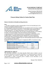
4S6<strong>Carbon</strong> <strong>Steel</strong> Buttwelding <strong>Fittings</strong> • DimensionsButtwelding <strong>Fittings</strong> to ASME B1<strong>6.</strong>9Stub EndsReturnsElbowsPrinted July 2010Diamof LapReducersNote 1 Long Short Radius ofFilletCapsLong ShortLong ShortODNominal sizePrinted July 201090 deg 45 deg 90 degD A B A O K O K E H F F R GDN NPS15 1 /2 21.3 38 16 76 48 25 76 51 3 3520 3 /4 2<strong>6.</strong>7 38 19 76 51 25 38 76 51 3 4325 1 33.4 38 22 25 76 56 51 41 38 51 102 51 3 5132 1 1 /4 42.2 48 25 32 95 70 64 52 38 51 102 51 5 6440 1 1 /2 48.3 57 29 38 114 83 76 62 38 64 102 51 6 7350 2 60.3 76 35 51 152 106 102 81 38 76 152 64 8 9265 2 1 /2 73.0 95 44 64 190 132 127 100 38 89 152 64 8 10680 3 88.9 114 51 76 229 159 152 121 51 89 152 64 10 12790 3 1 /2 101.6 133 57 89 267 184 178 140 64 102 152 76 10 140100 4 114.3 152 64 102 305 210 203 159 64 102 152 76 11 157125 5 141.3 190 79 127 381 262 254 197 76 127 203 76 11 185150 6 168.3 229 95 152 457 313 305 237 89 140 203 89 13 218200 8 219.1 305 127 203 610 414 406 313 102 152 203 102 13 270250 10 273.0 381 159 254 762 518 508 391 127 178 254 127 13 324300 12 323.8 457 190 305 914 619 610 467 152 203 254 152 13 381350 14 355.6 533 222 356 1067 711 711 533 165 330 305 152 13 413400 16 40<strong>6.</strong>4 610 254 406 1219 813 813 610 178 356 305 152 13 470450 18 457 686 286 457 1372 914 914 686 203 381 305 152 13 533500 20 508 762 318 508 1524 1016 1016 762 229 508 305 152 13 584550 22 559 838 343 559 1676 1118 1118 838 254 508 305 152 13 641600 24 610 914 381 610 1829 1219 1219 914 267 508 305 152 13 692650 26 660 991 405 267 610700 28 711 1067 438 267 610750 30 762 1143 470 267 610800 32 813 1219 502 267 610850 34 864 1295 533 267 610900 36 914 1372 565 267 610950 38 965 1448 600 305 6101000 40 1016 1524 632 305 6101050 42 1067 1600 660 305 6101100 44 1118 1676 695 343 6101150 46 1168 1753 727 343 7111200 48 1219 1829 759 343 711ELBOWRETURNNote 1: Reducer dimension "H" is based on large end nominal sizeNote squarecornerCAPEnlarged SectionREDUCER of LapSTUB ENDAll dimensions are in millimetres.www.atlassteels.com.auwww.atlassteels.com.au
<strong>Carbon</strong> <strong>Steel</strong> Buttwelding <strong>Fittings</strong> • DimensionsButtwelding Tees <strong>and</strong> Crosses to ASME B1<strong>6.</strong>9Printed July 2010Centreto-EndRunMCentre-to-End OutletChart of Commom Stainless <strong>Steel</strong> <strong>Pipe</strong> GradesChemical Analysis (%) SpecifiedC 8 10 15 20 25 32 40 50 65 80 90 100 125 150 200 250 300 350 400 450 500 550 600 650 700 750 800 850 900 950 1000 1050 1100 1150 1200OutsideDiam.DNominalSizeDN NPSPrinted July 20108 3 /8 13.710 1 /4 17.315 1 /2 21.3 25 25 25 2520 3 /4 2<strong>6.</strong>7 29 29 29 2925 1 33.4 38 38 38 3832 1 1 /4 42.2 48 49 48 48 4840 1 1 /2 48.3 57 57 57 57 57 5750 2 60.3 64 44 51 57 60 6465 2 1 /2 73.0 76 57 64 67 70 7680 3 88.9 86 70 73 76 83 8690 3 1 /2 101.6 95 79 83 89 92 95100 4 114.3 105 86 89 95 98 102 105125 5 141.3 124 105 108 111 114 117 124CROSS150 6 168.3 143 121 124 127 130 137 143200 8 219.1 178 152 156 162 168 178250 10 273.0 216 184 191 194 203 216300 12 323.8 254 216 219 229 241 254350 14 355.6 279 238 248 257 270 279400 16 40<strong>6.</strong>4 305 264 273 283 295 305 305450 18 457 343 298 308 321 330 330 343500 20 508 381 324 333 346 356 356 368 381550 22 559 419 359 371 381 381 394 406 419600 24 610 432 384 397 406 406 419 432 432 432650 26 660 495 422 432 432 444 457 470 483 495700 28 711 521 448 457 457 470 483 495 508 521 521750 30 762 559 460 473 483 483 495 508 521 533 546 546 559800 32 813 597 508 508 521 533 546 559 572 572 584 597850 34 864 635 533 546 559 572 584 597 597 610 622 635900 36 914 673 559 572 584 597 610 622 622 635 648 660 673950 38 965 711 TEE597 610 622 635 648 648 673 686 698 711 7111000 40 1016 749 622 635 648 660 673 673 698 711 724 737 749 7491050 42 1067 762 635 648 660 660 660 698 698 711 711 711 711 711 711 7111100 44 1118 813 686 686 698 698 698 711 711 724 724 737 749 762 7621150 46 1168 851 724 724 737 737 737 749 749 762 762 775 787 800 8001200 48 1219 889 737 737 762 762 762 787 787 787 813 813 813 838 838 838All dimensions are in millimetres.www.atlassteels.com.auwww.atlassteels.com.au5S6
6S6<strong>Carbon</strong> <strong>Steel</strong> Buttwelding <strong>Fittings</strong> • WeightsPrinted July 2010Sch 160Buttwelding <strong>Fittings</strong> (kgs per unit)XSSt<strong>and</strong>ard WeightPrinted July 2010Elbows Returns Stub EndsElbows ReturnsStub EndsElbowsTees Long Short Caps Reducers TeesXSODReducersCapsLong ShortCaps ReducersTees Long ShortLong ShortMSS ASME Long Short90 deg 45 deg 90 deg 90 deg 45 deg 90 degNominalsizeMSS ASME90 deg 45 deg 90 degmmDN NPS15 1 /2 21.3 0.08 0.04 0.16 0.04 0.12 0.14 0.09 0.10 0.05 0.20 0.05 0.13 0.12 0.11 0.12 0.06 0.1220 3 /4 2<strong>6.</strong>7 0.11 0.06 0.21 0.05 0.06 0.15 0.18 0.13 0.14 0.70 0.21 0.07 0.08 0.17 0.2 0.17 0.13 0.09 0.2125 1 33.4 0.16 0.08 0.11 0.31 0.21 0.11 0.12 0.19 0.3 0.25 0.20 0.10 0.14 0.41 0.26 0.15 0.15 0.24 0.38 0.32 0.25 0.13 0.17 0.2 0.19 0.4132 1 1 /4 42.2 0.26 0.13 0.18 0.52 0.35 0.14 0.16 0.26 0.41 0.43 0.35 0.18 0.23 0.70 0.46 0.20 0.21 0.35 0.55 0.56 0.42 0.21 0.28 0.25 0.25 0.6940 1 1 /2 48.3 0.37 0.19 0.25 0.74 0.49 0.17 0.25 0.38 0.55 0.61 0.50 0.25 0.33 1.02 0.66 0.24 0.33 0.46 0.68 0.81 0.65 0.33 0.43 0.35 0.43 1.0750 2 60.3 0.66 0.33 0.44 1.3 0.87 0.24 0.38 0.54 0.99 0.88 0.90 0.45 0.6 1.88 1.19 0.33 0.51 0.74 1.36 1.2 1.33 0.67 0.89 0.54 0.75 1.7865 2 1 /2 73.0 1.29 0.69 0.91 2.73 1.82 0.42 0.73 0.8 1.56 1.74 1.79 0.90 1.19 3.56 2.38 0.57 0.95 1.06 2.08 2.28 2.33 1.17 1.49 0.77 1.2 2.8680 3 88.9 2.04 1.02 1.36 4.07 2.71 0.67 0.94 1.13 2.13 2.41 2.74 1.37 1.83 5.74 3.65 0.92 1.25 1.51 2.84 3.25 3.83 1.92 2.55 1.4 1.71 4.5590 3 1 /2 101.6 2.94 1.47 1.97 5.65 3.77 0.92 1.19 1.47 2.58 3.26 4.05 2.02 207 12.72 5.21 1.3 1.64 2.01 3.51 4.51 5.92 2.96 3.95 2.1 2.35 <strong>6.</strong>52100 4 114.3 3.84 1.92 2.56 7.67 5.11 1.17 1.45 1.81 3.04 4.12 5.36 2.68 3.58 15.76 7.15 1.68 2.02 2.52 4.23 5.77 8.02 4.01 5.35 2.76 3 8.5125 5 141.3 <strong>6.</strong>48 3.24 4.32 13 8.64 1.9 2.5 2.53 5.3 <strong>6.</strong>54 9.13 4.57 <strong>6.</strong>09 19.39 12.2 2.73 3.52 3.6 7.52 9.2 14.7 7.35 9.79 4.85 5.59 14.8150 6 168.3 9.94 4.97 <strong>6.</strong>63 19.9 13.3 2.83 3.6 3.73 <strong>6.</strong>89 9.58 15 7.50 10 31.98 20 4.38 5.38 5.57 10.42 14.5 24.2 12.1 1<strong>6.</strong>2 7.81 8.63 23.3200 8 219.1 20.1 10.1 13.4 40.3 2<strong>6.</strong>8 5.11 5.7 5.89 10.42 17.9 30.5 15.3 20.3 64.33 40.7 7.91 8.63 10.12 15.86 27.1 53.2 2<strong>6.</strong>6 35.5 15.2 15 47.2250 10 273.0 35.4 17.7 23.6 70.8 47.2 8.92 9.6 10.42 18.12 30.4 47.7 23.9 31.8 99.66 74.9 12.2 12.9 13.95 24.28 41 103 51.5 68.6 28.9 27.5 88300 12 323.8 52 26 34.6 112 71.9 13.1 13.6 14.9 22.2 43.6 68.7 34.4 45.8 144.96 94.9 17.4 18 19.93 29.81 57.7 171 85.5 114 47.7 44.6 143350 14 355.6 67.9 34 45.3 15.9 25.4 15.5 28.3 53.5 89.9 15 60 21.2 33.6 21 38 70.9 236 118 158 61.2 88.5 186400 16 40<strong>6.</strong>4 89 44.5 59.1 20 31 18 32.7 6<strong>6.</strong>1 118 59 78.3 2<strong>6.</strong>7 41.1 24 44 87.7 350 175 234 92.8 121 260450 18 457 113 5<strong>6.</strong>5 75.3 25.5 37.8 21 37.5 83.9 150 75.5 100 34.1 50.1 28 50 111 495 247 330 131 165 356500 20 508 140 70 93.1 31.8 55.4 23.3 41.7 104 186 93 124 42.5 74.9 31 56 138 676 338 451 179 233 502550 22 559 169 84.5 113 38.8 62.4 25.8 4<strong>6.</strong>3 126 225 113 150 51.7 82.9 33 61 167 886 443 591 219 657600 24 610 202 101 135 45.1 68.4 28.4 50.5 139 268 134 179 60.1 91 37 67 186 1160 580 773 307 800650 26 660 237 119 158 50.5 89.4 176 315 158 210 67.3 119 234700 28 711 276 138 184 5<strong>6.</strong>2 9<strong>6.</strong>6 198 367 184 245 74.9 129 264750 30 762 316 158 211 62.1 104 228 421 211 281 82.8 138 304800 32 813 361 180 241 68.4 111 259 480 240 320 91.2 148 347850 34 864 406 204 272 75.4 116 295 543 272 362 100 158 393900 36 914 457 228 304 81.9 125 331 608 304 405 109 167 441950 38 965 510 255 340 94.7 133 370 679 339 453 126 177 4931000 40 1016 565 282 377 102 140 411 753 376 502 137 187 5471050 42 1067 622 311 416 110 147 422 828 414 554 147 196 5621100 44 1118 684 342 456 126 155 475 912 456 608 167 206 6331150 46 1168 748 374 499 134 189 521 997 498 665 179 252 6951200 48 1219 814 407 543 143 197 569 1085 542 724 191 263 759Note 1: All weights are approximatewww.atlassteels.com.auwww.atlassteels.com.au
Class 600 Flanges to ASME B1<strong>6.</strong>5Flange Weight (kg)DimensionsLength Thru Hub Bore Bolt DrillingNominal SizeRF StudBoltLength(mm)Bolts(No.)HoleDiameter(mm) HCircleDiameter(mm) KWeldingNeck /SocketWelding(mm) BSlip-on/SocketWeldingmin(mm) BWeldingNeck(mm) YSlip-on/SocketWeldingA h (mm) Y7S6<strong>Carbon</strong> <strong>Steel</strong> Flanges • Dimensions & WeightsNominal SizeHubDiameterWeldingNeck(mm)Note 1: To be specified by purchaser.Note 2: Flange weights are approximate.Note 3: Welding neck flange bore sizes listed are for sch 40S / St<strong>and</strong>ard Wall pipe.DN NPSFlangeOD(mm)OThickness Hubmin Diameter(mm) (mm)t fXHubDiameterWeldingNeck(mm)Class 150 Flanges to ASME B1<strong>6.</strong>5Slip-on/SocketWeldingA h (mm) YDimensionsLength Thru Hub Bore Bolt DrillingWeldingNeck(mm) YSlip-on/SocketWeldingmin(mm) BWeldingNeck /SocketWelding(mm) BCircleDiameter(mm) KHoleDiameter(mm) HBolts(No.)RF StudBoltLength(mm)RFMachineBoltLength(mm) Slip-onFlange Weight (kg)WeldingNeck Blind15 1⁄2 90 9.6 30 21.3 14 46 22.2 15.8 60.3 15.9 4 55 50 0.4 0.5 0.420 3⁄4 100 11.2 38 2<strong>6.</strong>7 14 51 27.7 20.9 69.9 15.9 4 65 50 0.6 0.7 0.625 1 110 12.7 49 33.4 16 54 34.5 2<strong>6.</strong>6 79.4 15.9 4 65 55 0.8 1.0 0.932 1 1 ⁄4 115 14.3 59 42.2 19 56 43.2 35.1 88.9 15.9 4 70 55 1.0 1.3 1.240 1 1 ⁄2 125 15.9 65 48.3 21 60 49.5 40.9 98.4 15.9 4 70 65 1.3 1.7 1.550 2 150 17.5 78 60.3 24 62 61.9 52.5 120.7 19.1 4 85 70 2.1 2.6 2.465 2 1 ⁄2 180 20.7 90 73.0 27 68 7<strong>6.</strong>6 62.7 139.7 19.1 4 90 75 3.3 4.1 3.980 3 190 22.3 108 88.9 29 68 90.7 77.9 152.4 19.1 4 90 75 3.9 4.9 4.990 3 1 ⁄2 215 22.3 122 101.6 30 70 103.4 90.1 177.8 19.1 8 90 75 4.8 <strong>6.</strong>1 <strong>6.</strong>2100 4 230 22.3 135 114.3 32 75 11<strong>6.</strong>1 102.3 190.5 19.1 8 90 75 5.3 <strong>6.</strong>8 7.0125 5 255 22.3 164 141.3 35 87 143.8 128.2 215.9 22.2 8 95 85 <strong>6.</strong>1 8.6 8.6100 4 230 22.3 135 114.3 32 75 11<strong>6.</strong>1 102.3 190.5 19.1 8 90 75 5.3 <strong>6.</strong>8 7.0125 5 255 22.3 164 141.3 35 87 143.8 128.2 215.9 22.2 8 95 85 <strong>6.</strong>1 8.6 8.6150 6 280 23.9 192 168.3 38 87 170.7 154.1 241.3 22.2 8 100 85 7.5 11 11200 8 345 27.0 246 219.1 43 100 221.5 202.7 298.5 22.2 8 110 90 12 18 20250 10 405 28.6 305 273.0 48 100 27<strong>6.</strong>2 254.6 362.0 25.4 12 115 100 17 24 29300 12 485 30.2 365 323.8 54 113 327.0 304.8 431.8 25.4 12 120 100 26 37 43350 14 535 33.4 400 355.6 56 125 359.2 Note (1) 47<strong>6.</strong>3 28.6 12 135 115 35 48 58400 16 595 35.0 457 40<strong>6.</strong>4 62 125 410.5 Note (1) 539.8 28.6 16 135 115 45 61 76450 18 635 38.1 505 457.0 67 138 461.8 Note (1) 577.9 31.8 16 145 125 49 68 94500 20 700 41.3 559 508.0 71 143 513.1 Note (1) 635.0 31.8 20 160 140 62 85 122600 24 815 4<strong>6.</strong>1 663 610.0 81 151 61<strong>6.</strong>0 Note (1) 749.3 34.9 20 170 150 87 115 186Nominal SizeDN NPSThickness Hubmin Diameter(mm) (mm)t fFlangeOD(mm)OThickness Hubmin Diameter(mm) (mm)t fXHubDiameterWeldingNeck(mm)Class 300 Flanges to ASME B1<strong>6.</strong>5Slip-on/SocketWeldingA h (mm) YDimensionsLength Thru Hub Bore Bolt DrillingWeldingNeck(mm) YSlip-on/SocketWeldingmin(mm) BWeldingNeck /SocketWelding(mm) BCircleDiameter(mm) KHoleDiameter(mm) HBolts(No.)RF StudBoltLength(mm)RFMachineBoltLength(mm) Slip-onFlange Weight (kg)WeldingNeck Blind15 1⁄2 95 12.7 38 21.3 21 51 22.2 15.8 6<strong>6.</strong>7 15.9 4 65 55 0.6 0.8 0.620 3⁄4 115 14.3 48 2<strong>6.</strong>7 24 56 27.7 20.9 82.6 19.1 4 75 65 1.2 1.3 1.225 1 125 15.9 54 33.4 25 60 34.5 2<strong>6.</strong>6 88.9 19.1 4 75 65 1.4 1.6 1.432 1 1 ⁄4 135 17.5 64 42.2 25 64 43.2 35.1 98.4 19.1 4 85 70 1.7 2.1 1.840 1 1 ⁄2 155 19.1 70 48.3 29 67 49.5 40.9 114.3 22.2 4 90 75 2.6 3.1 2.750 2 165 20.7 84 60.3 32 68 61.9 52.5 127.0 19.1 8 90 75 2.9 3.4 3.165 2 1 ⁄2 190 23.9 100 73.0 37 75 74.6 62.7 149.2 22.2 8 100 85 4.5 5.3 4.880 3 210 27.0 117 88.9 41 78 90.7 77.9 168.3 22.2 8 110 90 <strong>6.</strong>2 7.3 <strong>6.</strong>890 3 1 ⁄2 230 28.6 133 101.6 43 79 103.4 90.1 184.2 22.2 8 110 95 8.2 9.5100 4 255 30.2 146 114.3 46 84 11<strong>6.</strong>1 102.3 200.0 22.2 8 115 95 11 12125 5 280 33.4 178 141.3 49 97 143.8 128.2 235.0 22.2 8 120 110 15 16150 6 320 35.0 206 168.3 51 97 170.7 154.1 269.9 22.2 12 120 110 20 21200 8 380 39.7 260 219.1 60 110 221.5 202.7 330.2 25.4 12 140 120 30 35250 10 445 4<strong>6.</strong>1 321 273.0 65 116 27<strong>6.</strong>2 254.6 387.4 28.6 16 160 140 44 55300 12 520 49.3 375 323.8 71 129 327.0 304.8 450.8 31.8 16 170 145 64 79350 14 585 52.4 425 355.6 75 141 359.2 Note (1) 514.4 31.8 20 180 160 88 107400 16 650 55.6 483 40<strong>6.</strong>4 81 144 410.5 Note (1) 571.5 34.9 20 190 165 113 139450 18 710 58.8 533 457.0 87 157 461.8 Note (1) 628.6 34.9 24 195 170 138 177500 20 775 62.0 587 508.0 94 160 513.1 Note (1) 685.8 34.9 24 205 185 167 223600 24 915 68.3 702 610.0 105 167 61<strong>6.</strong>0 Note (1) 812.8 41.3 24 230 205 235 342FlangeOD(mm)ODN NPSWeldingNeck BlindSlip-onX15 1⁄2 95 14.3 38 21.3 22 52 22.2 Note (1) 6<strong>6.</strong>7 15.9 4 75 0.9 0.9 0.920 3⁄4 115 15.9 48 2<strong>6.</strong>7 25 57 27.7 Note (1) 82.6 19.1 4 90 1.4 1.6 1.425 1 125 17.5 54 33.4 27 62 34.5 Note (1) 88.9 19.1 4 90 1.8 1.9 1.832 1 1 ⁄4 135 20.7 64 42.2 29 67 43.2 Note (1) 98.4 19.1 4 95 2.6 2.5 2.440 1 1 ⁄2 155 22.3 70 48.3 32 70 49.5 Note (1) 114.3 22.2 4 110 3.2 3.6 3.450 2 165 25.4 84 60.3 37 73 61.9 Note (1) 127.0 19.1 8 110 3.9 4.5 4.465 2 1 ⁄2 190 28.6 100 73.0 41 79 74.6 Note (1) 149.2 22.2 8 120 5.9 <strong>6.</strong>4 <strong>6.</strong>880 3 210 31.8 117 88.9 46 83 90.7 Note (1) 168.3 22.2 8 125 7.4 8.1 8.990 3 1 ⁄2 230 35.0 133 101.6 49 86 103.4 Note (1) 184.2 25.4 8 140 12 13100 4 275 38.1 152 114.3 54 102 11<strong>6.</strong>1 Note (1) 215.9 25.4 8 145 17 19125 5 330 44.5 189 141.3 60 114 143.8 Note (1) 26<strong>6.</strong>7 28.6 8 165 31 31150 6 355 47.7 222 168.3 67 117 170.7 Note (1) 292.1 28.6 12 170 37 38200 8 420 55.6 273 219.1 76 133 221.5 Note (1) 349.2 31.8 12 190 51 62250 10 510 63.5 343 273.0 86 152 27<strong>6.</strong>2 Note (1) 431.8 34.9 16 215 86 102300 12 560 6<strong>6.</strong>7 400 323.8 92 156 327.0 Note (1) 489.0 34.9 20 220 103 132350 14 605 69.9 432 355.6 94 165 359.2 Note (1) 527.0 38.1 20 235 122 158400 16 685 7<strong>6.</strong>2 495 40<strong>6.</strong>4 106 178 410.5 Note (1) 603.2 41.3 20 255 177 225450 18 745 82.6 546 457.0 117 184 461.8 Note (1) 654.0 44.5 20 275 216 285500 20 815 88.9 610 508.0 127 190 513.1 Note (1) 723.9 44.5 24 285 268 365600 24 940 101.6 718 610.0 140 203 61<strong>6.</strong>0 Note (1) 838.2 50.8 24 330 372 533Printed July 2010www.atlassteels.com.au
8S6Class 2500 Flanges to ASME B1<strong>6.</strong>5Flange Weight (kg)DimensionsLength Thru Hub Bore Bolt DrillingNominal SizeRF StudBoltLength(mm)Bolts(No.)HoleDiameter(mm) HCircleDiameter(mm) KWeldingNeck /SocketWelding(mm) BSlip-on/SocketWeldingmin(mm) BWeldingNeck(mm) YSlip-on/SocketWeldingA h (mm) YHubDiameterWeldingNeck(mm)Thickness Hubmin Diameter(mm) (mm)t fFlangeOD(mm)ODN NPSWeldingNeck BlindSlip-on15 1⁄2 135 30.2 43 21.3 40 73 22.9 Note (1) 88.9 22.2 4 120 3.0 3.2 3.2X203 ⁄4 140 31.8 51 2<strong>6.</strong>7 43 79 28.2 Note (1) 95.2 22.2 4 125 3.6 4.1 4.525 1 160 35.0 57 33.4 48 89 34.9 Note (1) 108.0 25.4 4 140 5.0 5.5 5.432 1 1 ⁄4 185 38.1 73 42.2 52 95 43.7 Note (1) 130.2 28.6 4 150 7.3 9.1 8.240 1 1 ⁄2 205 44.5 79 48.3 60 111 50.0 Note (1) 14<strong>6.</strong>0 31.8 4 170 10 11 1050 2 235 50.9 95 60.3 70 127 62.5 Note (1) 171.4 28.6 8 180 17 19 1865 2 1 ⁄2 265 57.2 114 73.0 79 143 75.4 Note (1) 19<strong>6.</strong>8 31.8 8 195 24 24 2580 3 305 6<strong>6.</strong>7 133 88.9 92 168 91.4 Note (1) 228.6 34.9 8 220 36 43 39100 4 355 7<strong>6.</strong>2 165 114.3 108 190 11<strong>6.</strong>8 Note (1) 273.0 41.3 8 255 54 64 60125 5 420 92.1 203 141.3 130 229 144.4 Note (1) 323.8 47.6 8 300 93 111 101150 6 485 108.0 235 168.3 152 273 171.4 Note (1) 368.3 54.0 8 345 143 176 157200 8 550 127.0 305 219.1 178 318 222.2 Note (1) 438.2 54.0 12 380 213 261 241250 10 675 165.1 375 273.0 229 419 277.4 Note (1) 539.8 6<strong>6.</strong>7 12 490 409 484 465300 12 760 184.2 441 323.8 254 464 328.2 Note (1) 619.1 73.0 12 540 573 692 664Note 1: To be specified by purchaser.Note 2: Flange weights are approximate.Note 3: Welding neck flange bore sizes listed are for sch 40S / St<strong>and</strong>ard Wall pipe.<strong>Carbon</strong> <strong>Steel</strong> Flanges • Dimensions & WeightsClass 900 Flanges to ASME B1<strong>6.</strong>5Flange Weight (kg)DimensionsLength Thru Hub Bore Bolt DrillingNominal SizePrinted July 2010RF StudBoltLength(mm)Bolts(No.)HoleDiameter(mm) HCircleDiameter(mm) KWeldingNeck /SocketWelding(mm) BSlip-on/SocketWeldingmin(mm) BWeldingNeck(mm) YSlip-on/SocketWeldingA h (mm) YHubDiameterWeldingNeck(mm)Thickness Hubmin Diameter(mm) (mm)t fPrinted July 2010FlangeOD(mm)ODN NPSWeldingNeck BlindSlip-on15 1⁄2 120 22.3 38 21.3 32 60 22.2 Note (1) 82.6 22.2 4 110 1.8 2.1 1.9X203 ⁄4 130 25.4 44 2<strong>6.</strong>7 35 70 27.7 Note (1) 88.9 22.2 4 115 2.3 2.7 2.725 1 150 28.6 52 33.4 41 73 34.5 Note (1) 101.6 25.4 4 125 3.4 3.9 4.132 1 1 ⁄4 160 28.6 64 42.2 41 73 43.2 Note (1) 111.1 25.4 4 125 4.1 4.5 4.340 1 1 ⁄2 180 31.8 70 48.3 44 83 49.5 Note (1) 123.8 28.6 4 140 5.5 5.9 5.950 2 215 38.1 105 60.3 57 102 61.9 Note (1) 165.1 25.4 8 145 11 11 1165 2 1 ⁄2 245 41.3 124 73.0 64 105 74.6 Note (1) 190.5 28.6 8 160 16 16 1680 3 240 38.1 127 88.9 54 102 90.7 Note (1) 190.5 25.4 8 145 12 15 13100 4 290 44.5 159 114.3 70 114 11<strong>6.</strong>1 Note (1) 235.0 31.8 8 170 23 23 25125 5 350 50.8 190 141.3 79 127 143.8 Note (1) 279.4 34.9 8 190 38 39 39150 6 380 55.6 235 168.3 86 140 170.7 Note (1) 317.5 31.8 12 190 48 50 52200 8 470 63.5 298 219.1 102 162 221.5 Note (1) 393.7 38.1 12 220 75 79 59250 10 545 39.9 368 273.0 108 184 27<strong>6.</strong>2 Note (1) 469.9 38.1 16 235 111 118 132300 12 610 79.4 419 323.8 117 200 327.0 Note (1) 533.4 38.1 20 255 146 157 187350 14 640 85.8 451 355.6 130 213 359.2 Note (1) 558.8 41.3 20 275 172 182 224400 16 705 88.9 508 40<strong>6.</strong>4 133 216 410.5 Note (1) 61<strong>6.</strong>0 44.5 20 285 193 225 272450 18 785 101.6 565 457.0 152 229 461.8 Note (1) 685.8 50.8 20 325 272 309 386500 20 855 108.0 622 508.0 159 248 513.1 Note (1) 749.3 54.0 20 350 331 377 488600 24 1040 139.7 749 610.0 203 292 61<strong>6.</strong>0 Note (1) 901.7 6<strong>6.</strong>7 20 440 632 685 905Class 1500 Flanges to ASME B1<strong>6.</strong>5Flange Weight (kg)DimensionsLength Thru Hub Bore Bolt DrillingNominal SizeRF StudBoltLength(mm)Bolts(No.)HoleDiameter(mm) HCircleDiameter(mm) KWeldingNeck /SocketWelding(mm) BSlip-on/SocketWeldingmin(mm) BWeldingNeck(mm) YSlip-on/SocketWeldingA h (mm) YHubDiameterWeldingNeck(mm)Thickness Hubmin Diameter(mm) (mm)t fFlangeOD(mm)ODN NPSWeldingNeck BlindSlip-on15 1⁄2 120 22.3 38 21.3 32 60 22.2 Note (1) 82.6 22.2 4 110 1.8 2.1 1.9X203 ⁄4 130 25.4 44 2<strong>6.</strong>7 35 70 27.7 Note (1) 88.9 22.2 4 115 2.8 2.7 2.725 1 150 28.6 52 33.4 41 73 34.5 Note (1) 101.6 25.4 4 125 3.6 3.9 4.132 1 1 ⁄4 160 28.6 64 42.2 41 73 43.2 Note (1) 111.1 25.4 4 125 5.0 4.5 4.340 1 1 ⁄2 180 31.8 70 48.3 44 83 49.5 Note (1) 123.8 28.6 4 140 <strong>6.</strong>8 5.9 5.950 2 215 38.1 105 60.3 57 102 61.9 Note (1) 165.1 25.4 8 145 11 11 1165 2 1 ⁄2 245 41.3 124 73.0 64 105 74.6 Note (1) 190.5 28.6 8 160 16 16 1680 3 265 47.7 133 88.9 117 Note (1) 203.2 31.8 8 180 22 22100 4 310 54.0 162 114.3 124 Note (1) 241.3 34.9 8 195 31 33125 5 375 73.1 197 141.3 156 Note (1) 292.1 41.3 8 250 59 60150 6 395 82.6 229 168.3 171 Note (1) 317.5 38.1 12 260 75 75200 8 485 92.1 292 219.1 213 Note (1) 393.7 44.5 12 290 124 137250 10 585 108.0 368 273.0 254 Note (1) 482.6 50.8 12 335 206 230300 12 675 123.9 451 323.8 283 Note (1) 571.5 54.0 16 375 306 316350 14 750 133.4 495 355.6 298 Note (1) 635.0 60.3 16 405 416 421400 16 825 14<strong>6.</strong>1 552 40<strong>6.</strong>4 311 Note (1) 704.8 6<strong>6.</strong>7 16 445 568 559450 18 915 162.0 597 457.0 327 Note (1) 774.7 73.0 16 495 736 761500 20 985 177.8 641 508.0 356 Note (1) 831.8 79.4 16 540 929 967600 24 1170 203.2 762 610.0 406 Note (1) 990.6 92.1 16 615 1504 1568www.atlassteels.com.auwww.atlassteels.com.au
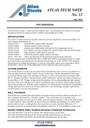
<strong>Carbon</strong> <strong>Steel</strong> Flanges • Dimensions & WeightsTable F Flanges to AS 2129Table D Flanges to AS 2129Printed July 2010Dimensions(mm) Weight (kg)Dimensions(mm) Weight (kg)Drilling DrillingNominalSizeBolt Size& Thread SOW BlindNumberof BoltsBolt HoleDiamHBolt CircleDiamKRaisedFaceDiamGNominalSizeHDCGKASLIP-ON WELDING (SOW)(“BOSS”)HDGKABLIND(“BLANK”)HDCGKAWELDING NECK (WN)HDGKAPLATEDiagrams above show the optional Raised FreePrinted July 2010Bolt Size& Thread SOW BlindNumberof BoltsBolt HoleDiamHBolt CircleDiamKRaisedFaceDiamGFlangeThicknessDFlangeODADNThicknessDDN ODA15 95 10 47 67 14 4 M12 0.6 0.720 100 10 53 73 14 4 M12 0.7 0.825 120 10 63 87 18 4 M16 0.9 1.032 135 13 74 98 18 4 M16 1.1 1.340 140 13 81 105 18 4 M16 1.2 1.450 165 16 103 127 18 4 M16 2.2 2.665 185 16 122 146 18 4 M16 2.5 3.080 205 16 141 165 18 8 M16 3.0 3.890 215 19 154 178 18 8 M16100 230 19 167 191 18 8 M16 4.3 5.9125 280 22 207 235 22 8 M20 7.4 10.1150 305 22 232 260 22 12 M20 8.1 11.9200 370 35 296 324 22 12 M20 12.7 20.3250 430 29 349 381 26 12 M24 18.1 31.4300 490 32 406 438 26 16 M24 23.9 44.7350 550 35 459 495 30 16 M27 35.3 63.0400 610 41 516 552 30 20 M27 47.6 90.0450 675 44 571 610 33 20 M30 62.0 120.0500 735 51 634 673 33 24 M30 80.0 162.0550 785 54 685 724 33 24 M30600 850 57 739 781 36 24 M33 112.0700 935 60 815 857 36 24 M33750 1015 67 898 940 36 28 M33800 1060 68 942 984 36 28 M33850 1090 70 974 1016 36 32 M33900 1185 76 1060 1105 39 32 M361000 1275 83 1149 1194 39 36 M361200 1530 95 1385 1441 42 40 M3915 95 *5 47 67 14 4 M12 0.6 0.620 100 *5 53 73 14 4 M12 0.7 0.725 115 *5 65 83 14 4 M12 0.9 1.032 120 *6 67 87 14 4 M12 0.9 1.140 135 *6 78 98 14 4 M12 1.2 1.450 150 *8 90 114 18 4 M16 1.4 1.765 165 *8 103 127 18 4 M16 1.6 2.180 185 *10 122 146 18 4 M16 2.0 2.790 205 *10 141 165 18 4 M16 2.2 3.2100 215 *10 154 178 18 4 M16 2.5 3.6125 255 13 186 210 18 8 M16 3.3 4.9150 280 13 211 135 18 8 M16 4.0 <strong>6.</strong>1200 335 13 268 292 18 8 M16 5.0 8.8250 405 16 328 256 22 8 M20 8.7 15.8300 455 19 378 406 22 12 M20 11.3 23.6350 525 22 438 470 26 12 M24 19.6 38.6400 580 22 489 521 26 12 M24 22.3 44.9450 640 25 532 584 26 12 M24 29.0 63.0500 705 29 609 641 26 16 M24 39.9 8<strong>6.</strong>0550 760 29 637 699 30 16 M27 50.0 107.0600 825 32 720 756 30 16 M27 58.0 125.0700 910 35 809 845 30 20 M27750 995 41 888 927 33 20 M30800 1060 41 942 984 36 20 M33850 1090 44 974 1016 36 20 M33900 1175 48 1050 1092 36 24 M331000 1255 51 1133 1175 36 24 M331200 1490 60 1368 1410 36 32 M33Table H Flanges to AS 2129Table E Flanges to AS 2129Dimensions(mm) Weight (kg)RaisedDrillingA D G K HFlange Flange Face Bolt Circle Bolt Hole Number Bolt SizeOD Thickness Diam Diam Diam of Bolts & Thread SOW BlindWeight (kg)NominalSizeDrillingDimensions(mm)NominalSizeDNBolt Size& Thread SOW BlindNumberof BoltsBolt HoleDiamHBolt CircleDiamKRaisedFaceDiamGThicknessDDN ODA15 115 13 57 83 18 4 M16 0.8 1.020 115 13 57 83 18 4 M16 0.9 1.025 120 14 64 87 18 4 M16 1.1 1.232 135 17 76 98 18 4 M16 1.5 1.840 140 17 83 105 18 4 M16 1.7 2.050 165 19 102 127 18 4 M16 2.6 3.165 185 19 114 146 18 8 M16 3.1 3.880 205 22 127 165 18 8 M16 4.3 5.490 215 22 140 178 18 8 M16100 230 25 152 191 18 8 M16 5.8 7.9125 280 29 178 235 22 8 M20 9.9 12.6150 305 29 210 260 22 12 M20 10.8 15.4200 370 32 260 324 22 12 M20 18.3 28.2250 430 35 311 381 26 12 M24 22.1 38.0300 490 41 362 438 26 16 M24 31.0 58.0350 550 48 419 495 30 16 M27 47.7 85.0400 610 54 483 552 30 20 M27 62.0 118.0450 675 60 533 610 33 20 M30 105.0 19<strong>6.</strong>0500 735 67 597 673 33 24 M30550 785 70 648 724 33 24 M30600 850 76 699 781 36 24 M33Note 1: All weights are approximateNote 2: A diametrical clearance of 4mm maximum applies to pipe or tube OD for plate flangesNote 3: The flange thickness "D" dimension includes the raised face heightNote 4: Welding Neck bore is derived from the pipe schedule*Plate flanges less than 12.0mm thickness may suffer unacceptabledistortion after welding to the pipe.15 95 *6 47 67 14 4 M12 0.6 0.720 100 *6 53 73 14 4 M12 0.7 0.825 115 *7 63 83 14 4 M12 0.9 1.032 120 *8 67 87 14 4 M12 1.0 1.140 135 *9 78 98 14 4 M12 1.2 1.450 150 *10 90 114 18 4 M16 1.4 1.765 165 *10 103 127 18 4 M16 1.6 2.180 185 *11 122 146 18 4 M16 2.0 2.790 205 12 141 165 18 8 M16100 215 13 154 178 18 8 M16 2.5 3.6125 255 14 186 210 18 8 M16 3.7 5.5150 280 17 207 235 22 8 M20 5.0 8.3200 335 19 264 292 22 8 M20 7.1 12.9250 405 22 328 356 22 12 M20 11.4 21.9300 455 25 374 406 26 12 M24 15.1 31.8350 525 29 438 470 26 12 M24 25.3 47.6400 580 32 489 521 26 12 M24 31.3 6<strong>6.</strong>0450 640 35 552 584 26 16 M24 40.8 87.0500 705 38 609 641 26 16 M24 53.0 114.0550 760 44 663 699 30 16 M27600 825 48 717 756 33 16 M30 85.0 195.0700 910 51 806 845 33 20 M30750 995 54 885 927 36 20 M33800 1060 54 942 984 36 20 M33850 1090 57 974 1016 36 20 M33900 1175 64 1050 1092 36 24 M331000 1255 67 1130 1175 39 24 M361200 1490 79 1365 1410 39 32 M36www.atlassteels.com.auwww.atlassteels.com.au9S6
ATLAS STEELS – PRODUCT REFERENCE MANUALSECTION 6: CARBON STEEL PIPE, FITTINGS, FLANGES AND TUBE<strong>Carbon</strong> <strong>Steel</strong> <strong>Tube</strong>Heat Exchangers, Hydraulic <strong>and</strong> Pneumatic <strong>Tube</strong>10S6<strong>Carbon</strong> steel tubing finds common application in two major areas; heat transferin heat exchangers <strong>and</strong> condensers, <strong>and</strong> as hydraulic <strong>and</strong> pneumatic tubing.This tube is produced as a seamless tube, with a final cold draw to guaranteedimensional tolerances <strong>and</strong> an excellent surface finish. In common with otherproduct this cold-drawn carbon steel tube is made to an all-plus tolerance ifintended for heat transfer applications, but is generally supplied with nominalwall thickness (+/- tolerance) for hydraulic or pneumatic applications.Stock range generally caters for applications in hydraulic <strong>and</strong> pneumatic tubing.The projects department offers sourcing for materials used in other applicationsaccording to customer specifications. These include heat exchanger tubes in st<strong>and</strong>ardmill lengths <strong>and</strong>/or specific set lengths.SpecificationsASTM A179M ‘St<strong>and</strong>ard Specification for Seamless Cold-Drawn Low-<strong>Carbon</strong><strong>Steel</strong> Heat-Exchanger <strong>and</strong> Condenser <strong>Tube</strong>s’ covers minimum wall thickness tube forheat transfer applications in sizes 3.18mm to 7<strong>6.</strong>2mm OD.The specification for heat exchanger tube is also used to specify seamless carbon steeltube intended for hydraulic applications. This hydraulic tubing is manufactured withaverage wall thickness specified; in all other respects the product conforms to therequirements of ASTM A179M <strong>and</strong> ASTM A450M.Product intended for hydraulic applications has nominal wall thicknesses in the SWGseries of sizes, while the minimum wall thickness heat exchanger tube is generallyin line with the BWG series.In addition to the ASTM A179 tube stocked in heat exchanger <strong>and</strong> hydraulic variants,welded carbon steel tube can be obtained to either ASTM A178 or ASTM A214.Printed July 2010www.atlassteels.com.au
ATLAS STEELS – PRODUCT REFERENCE MANUALSECTION 6: CARBON STEEL PIPE, FITTINGS, FLANGES AND TUBEHydraulic <strong>and</strong> pneumatic carbon steel tubingTypical size range <strong>and</strong> tolerancemmNominalODinchesODpermissibledeviation(mm)Wall thickness (mm)0.90/0.91 1.20/1.22 1.60/1.63 2.00/2.03 2.64 3.25 4.06 4.88 <strong>6.</strong>40Gauge20 18 16 14 12 10 8 6 3<strong>6.</strong>357.949.531/ 45/ 163/ 8+_ 0.10+_ 0.10+_ 0.1011S612.701/ 2+_ 0.1015.885/ 8+_ 0.1019.053/ 4+_ 0.1022.237/ 8+_ 0.1025.401+_ 0.1531.751 1 / 4+_ 0.1538.101 1 / 2+_ 0.1550.802+_ 0.20Stock length – <strong>6.</strong>1 metres.Note: Gold zinc coating is available on request.Printed July 2010www.atlassteels.com.au
www.atlassteels.com.au