Installation Instructions - Pioneer SL Series - Cal-Royal
Installation Instructions - Pioneer SL Series - Cal-Royal
Installation Instructions - Pioneer SL Series - Cal-Royal

You also want an ePaper? Increase the reach of your titles
YUMPU automatically turns print PDFs into web optimized ePapers that Google loves.
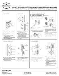
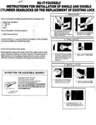
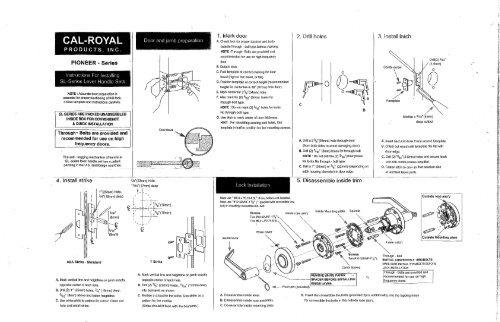
CAL-ROYALPRODUCTS, INC.PIONEER - <strong>Series</strong><strong>Instructions</strong> For Installing ,<strong>SL</strong> -<strong>Series</strong> Lever Handle SetsNOTE: Accurate door preparation isessential for proper functioning of this ·Iock.Follow template and instructions carefully.<strong>SL</strong> SERIES ARE PACKED UNASSEMBLEDINSIDE BOX FOR CONVENIENCE& QUICK INSTALLATIONThrough- Bolts are provided andrecommended for use on highfrequency doors.The anti - sagging mechanism of handle in<strong>SL</strong> -series lever handle set has a patentpending in the U.S. and foreign countries.4. Install strikeASA Blril,e .. Siandard1" (25mm) Hole,3/4"(19mm) deepA. Mark vertical line and heightline on jamb exactlyopposite center of latch hole.B. Drill (2) 1" (25mm) holes. 3/4' (19mm) deep,5/16" (8mm) above and below heightline.C. Use strike plate to pattern for cutout. Clean outhole and install strike.7/s" (22mm) Hole,"/'6"(17mm) deep,,"ff ',,". • 1Door and Jamb preparation I,. .1Door bevel!-- , ,, , !-+----+-L-" j3/ s "(10mm)'3/i'(10mm)T Slril,.A. Mark vertical line and heightline on jamb exactlyopposite center of latch hole.B. Drill (2) 7/s" (22mm) holes, "/,6" (17mm) deep,into doorjamb as shown,C. Mortise a cutout for the strike. Use strike as apattern for the mortise.(Strike should fit flush with the doorjamb.)1. Mark doorA. Check lock for proper backset and bodyoutside through - bolt type before Inarking.NOTE :Through- Bolts are provided andrecommended for use on high frequencydoorS, Detach stub.C. Fold template at correct marking for doorbevel (high or low bevel, or flat).D. Position template at correct height (recommendedheight for centerline is 38" (97cm) from floor).E. Mark center for 21/a"(54mm) hole.F. Also mark for (2) 5/,6" (8mm) holes forthrough-bolt type.NOTE: Do not mark (2) 5/,6" holes for locksNo through-bolt type.G. Use stub to mark center of door thickness.HINT: For retrofiUing existing lock holes, foldtemplate in half to position for the mounting screws.Lock <strong>Installation</strong>, ,Must use "MB.O x PO.75-S.5L" If thru bolts is not installed.Musl use "#10-32UNF-11/a" L" (packed wilh convertible Ihruboll) in installing convertible thru bolt.Inside leverA. Disassemble inside lever.Rose cover ~S, Disassemble inside rose assembly.C. Disassemble inside mounting plate.2. Drill holescInside rose ass'yoA. Drill a 21/s"(54mm) hole through door(from both sides to avoid damaging door).B. Drill (2) 5/,6" (8mm) holes for through boltNOTE: Do not drililhe (2) 5/ ,6 " (8mm)holesfor locks No through - bolt typeC. Drill a 1" (25mm) or 7/S" (22mm) (depending onlatch housing diameter) in door edge.5. Disassemble inside trimInside Mounling plateREMOVE WHITE PAPER -Spindle----~~~---iSPACER BEFORE INSTALLINGINSIDE LEVER.;.t~ ;f;!{';fJif'~.rff:- 'f-fI~~!1~>'1f~:-I!»;lf1 Ie!,JI'Ijf 'lIfi~-1,.•'-,'~.jy~~;;jIII ?,' ;f(!;~- ,
Adjustfor door thicknessLOCKSET IS FACTORY PRESET FOR 1314" (4Smm) DOORS.See step 6 to center chassIs In door or to change adjustment of othel door thicknessesutside Mounting plate~ ~Adjust to 9/64" for1 3/S fl door~ HousingAdjust to 11/32" for1 3/4 J1 doorADJUSTMENT fOR DOOR THICKNESSInstall inside rose assemblyIt can be adjusted for door thickness range from1 3 /a"to 1 3 /4"For adjustment of door thickness,follow step 11, then:A. Adjust outside mounting plate for proper doorthickness. At final position, the screw post holemust be in line with holes in lockbody.B. Slide outside rose ass'y with rose cover ontospindle with the wider. notch at inside diameter inline with lever catch.The screw posts will enter the holes pre-alignedbetween outside mounting plate and lockbody.NOTE See Step 11 must be done It you have, to make adjustments for door tllIckness10. Install inside lever'~;J"7, Install outside lock unitEngage prongsIMPORTANT, Place outside lock unit Into position"Make sure that latch prongs engage chaSSIS housing,and latch retlaciel engages latch balHow to remove & reassembleoutside lever. ,11. Remove outside leverOutside lever~~-~~p-------o11 Install lVIounting plate,. _----', .A. Hold outside unit in place.B. Put mounting plate into position on chassis.CAUTION: When using power screwdriver forinstallation, set to minimum torque setting.Drill (4) 9ie/~~~, ~~ 0C. Place mounting plate. Tighten it to lock body with two #10 - 32UNFx 1 1 /a"L screws, _" Combi Screws~-~~ NOTE1: Two#10· 32UNFx 1 1 t,'L screws(*)NOTE 2: Two MB.Ox PO.7SX8.<strong>SL</strong> scrAWRD. Drill (4) 9/ 6 / (3.5mm) holes and secure the mounting plate with four combi-screws supplied.THIS MUST BE DONE TO FIRMLY ANCHOR LOCK TO DOORE. Place inside rose ass'y. Tighten it to lock body with screws supplied.NOTE1: Two #10· 32UNFx 11/{L(-k) screws can be used for outside through - bolt type only.NOTE 2 : Two M6.0 x PO.75 x 8.5L screws can be used for no through - bolt type only.12. Reassemble outside leverReverse Step 11 to. reassemble levers.A. To reassemble. Put a cylinder and key in lever.B. Push cylinder further in until it engages retractor.C. Turn key 90 0 clockwise and hold a key.D. Depress lever catch and push lever (Not I~ey) inuntil it clicks then release a key.~/" "'Key• CAUTION FOR CLASSROOM FUNCTICam,adA1lloq-46noJ41 ap!Slno ln041!M S>l:)OI JOJS810ll 841 8>1BW lOU 00 : 3l.0N,,~----------~----~----------------~,N,-,," ~, , ~O,"Ill;': ,,...- ,:z e ,,~~:,: ....~.!!1 ,.:~a:~,, ,,fr,IDriverISASS MOAlign dimples on rose with grooves in inside'Ose assembly.Place rose against door and rotate clockwise untillimples snap into slots next to the grooves.A. Slide inside lever onto spindle.Push lever completely into place. (Pull on lever tomake sure that catch is fully engaged.)B. Test operation of lock to make sure you havefollowed instructions correctly.A. Insert key into cylinder. Insert push pin (or similar tool)into hole in lever. Turn key one - quarter turn and push tool(push pin) to depress lever catch. Slide the lever from spindle.Make sure. to turn cam anti - clockwise bydriver as far as it will go before reassembling ofcylinder to pre~~nt mis-p"6sitioning of cam forclassroom function.ISASS uo ~BI.:I---+---0-1