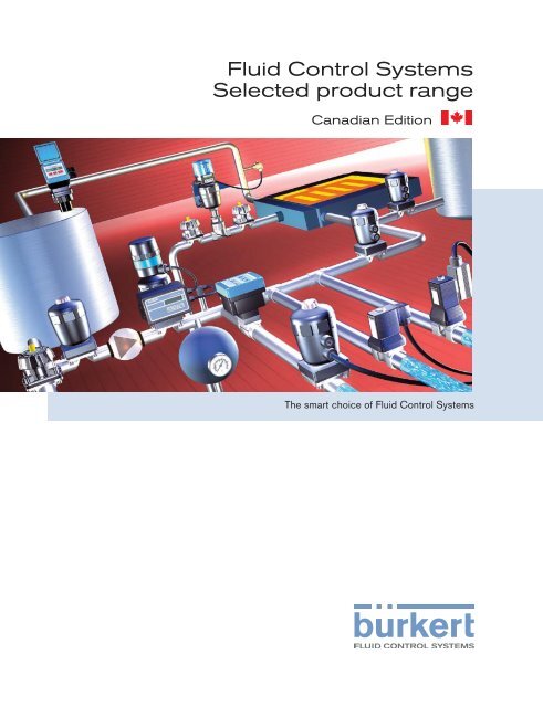
Fluid Control Systems Selected product range
Fluid Control Systems Selected product range
Fluid Control Systems Selected product range

You also want an ePaper? Increase the reach of your titles
YUMPU automatically turns print PDFs into web optimized ePapers that Google loves.
<strong>Fluid</strong> <strong>Control</strong> <strong>Systems</strong><strong>Selected</strong> <strong>product</strong> <strong>range</strong>Canadian EditionThe smart choice of <strong>Fluid</strong> <strong>Control</strong> <strong>Systems</strong>
All the technical data presented in this catalogue is valid at the time of printing. As we are continuously improving and developing our<strong>product</strong>s, we reserve the right to introduce modifications to the technical data at any time. As a consequence, we cannot accept legalliability for the above information, nor for any printing mistakes that may have occured.Burkert Contromatic Inc.760 Pacific RoadUnit 3Oakville, Ontario L6L 6M5CANADABürkert GmbH & Co. KG<strong>Fluid</strong> <strong>Control</strong> <strong>Systems</strong>Christian-Bürkert-Strasse 13-17DE-74 653 IngelfingenGERMANY
Your personal copy of the newBürkert <strong>Fluid</strong> <strong>Control</strong> <strong>Systems</strong> CatalogueDear customer, this catalogue is meant to be a guide to enable you to quickly find the mostsuitable solution for your needs.The catalogue is organised in chapters, starting with Solenoid Valves, and then walking youthrough the main <strong>product</strong> areas such as Process Valves, Process Pneumatics, Analytical Valvesand Sensors.Each section includes a selection guide / overview of the <strong>product</strong> area, which enables you tochoose the right <strong>product</strong> for your needs: pressure <strong>range</strong>, diameters, voltage, etc. You can thenproceed to look at the specific datasheet of the <strong>product</strong> you are interested in.The articles illustrated in this document are a selection from our complete programme: shouldyou need details of a <strong>product</strong> that is not described, please visit our website at www.burkert.com.Here you will find the latest datasheets and operating manuals of our full programme.Should you need further assistance, please do not hesitate to contact the Bürkert subsidiarynearest to you: a worldwide list is provided at the end of this catalogue.We’ll be pleased to assist you further by looking at your specific needs / applications, by informingyou about our stock items and providing any additional information / service you may need.Looking forward to hearing from you soon!Bürkert – Your business partner
Bürkert worldwideWith our subsidiaries, we are present in more than 30 countries.You can benefit from our full <strong>range</strong> of services wherever you needthem.Fast repair serviceOur Service Centres are at your disposal to solve any technical orquality problems you may experience. The repair/replacement willbe carried out professionally and in the shortest possible time.www.burkert.com/On www.burkert.com you will find detailed informationabout Bürkert, the latest version of all technicalinformation about our <strong>product</strong>s and software programmesto help make your work easier.InfoThe Bürkert Teams are at your disposal for any additional technicalor application-oriented information. Contact us at our localoffices: we can offer you individual counselling and engineeringsupport.Quality certificationOur <strong>product</strong>s reflect our high quality standards and are also availableaccording to a wide <strong>range</strong> of International Certifications, suchas DVGW, UL, CSA, VDE, GL, JIS, FM, etc.Customised service and trainingOn request, we will support you during the installation and commissioningphases, and can provide training for your staff on our<strong>product</strong>s and systems.Index0S020Page292, 338S030 268SE30 Ex 2580121 58, 2420124 56, 2400127 54, 2380131 600142 800255 320256 360290 740330 460331 50, 1880340 88, 1940344 90, 1960355 440406 840407 8611066 961067 971078-1 3661078-2 3681094 35822000Page10266011Page24, 16488020Page2782002 106 6012 172 8025 T 2802012 110 6012 P 176 8025 B 2842030 118 6013 28, 168 8030 2562031 GP 122 6013 EEx 380 8031 2542031 forged 126 6014 40, 178 8032 2622032 140 6014 EEx 382 8035 T 2642033 142 6014 EEx i 396 8035 B 2662506 408 6014 P 182 8041 2882507 406 6022 352 8045 2902508 404 6023 352 8055 3002509 404 6024 354 8072 2742702 150 6106 184 8205 3222712 152 6211 62 8206 3262731 154 6213 68 8225 3302821 352 6213 HP 72 8226 3346223 356 8311 30836518 198 8314 3103003 148 6518 EEx i 398 8323 3123232 130 6519 EEx i 398 8400 3163233 GP 132 6519 198 8623-2 3703233 forged 136 6519 Namur 202 8624-2 3723234 144 6519 Namur EEx m 394 8625-2 3743235 146 6519 EEx m 390 8626 3616519 Namur EEx i 400 8630 97, 15056526 216 8631 965281 64 6527 216 8635 975281 EEx 384 6604 228 8640 2205282 76 6606 232 8644 2225282 EEx 386 6608 236 8711 3605404 82, 1928712 3605420 2048716 3615470 E 2065470 M 2085470 R 212
Experience you can rely onBürkert is an international company concentrating onconsultancy,systems development, innovation andquality in fluid controlBürkert offers global experience you can rely on, from a flexible organisationwith flexible processes. Day to day we are committed to creatingsuccess for our customers and ourselves. Consistent and continuousinvestment in research & development and in staff training enables us tooffer our customers the best in technology and services.For any request or target you might have for your fluid process control,you can rely on us: working together with you, we’ll find the best solution,both from a technical and economic point of view.As Bürkert has grown, sales activities abroad have expanded, supportedby an increasing number of subsidiaries in key industrialised countries.Our global presence enables us to focus on the most topical problemsin specific markets, whilst offering our customers the most efficientsolutions in their country. The result is a worldwide network that todayconsists of:• Four research & development centres• Seven <strong>product</strong> locations• 40 branch offices• 1,700 employeesFor more information visit: www.burkert.com
automotivefood and beveragetextilewater treatmentpharmaceuticalbiotechnologyanalysissemiconductorchemicalgenetic engineeringmedicalpackagingelectronicsmachine buildingcosmeticenergy
Solenoid valvesA uniquecomprehensive <strong>range</strong>of <strong>product</strong>sBürkert <strong>product</strong>s and systems can be employed wherever fluid mediaand gases need to be measured, controlled and regulated. Whether theapplication is filling, level, flow, pressure or temperature we have thesolution and a unique comprehensive <strong>range</strong> of <strong>product</strong>s to handle it,including solenoid, process and analytical valves, pneumatic actuation,sensors and controllers.reliableruggedleadershipFor Bürkert it is not enough to simply offer individual <strong>product</strong>s. Our aimis to provide complete system and application solutions that meet thespecific needs of our customers. Tell us what you need and our engineerswill find an appropriate solution using our vast experience and a wide<strong>range</strong> of services such as advice and engineering, installation, testingand after-sales support.Type 6211 page 62Type 6213 HP page 72Bürkert’s global presence offers our customers an additional advantage.Products and systems are constantly developed and optimised accordingto international standards. Through this process synergy effects evolvewhich ensure technological leadership and competitive advantage.So whether you need a single component or a fully integrated system,call Bürkert first. It could be the only call you need to make.For more information visit: www.burkert.com
BürkertsolutionsBürkert’s <strong>product</strong> selection is one of the widest on the market and so is the <strong>range</strong>of industries and applications Bürkert can serve with its global presence, whichreaches 30 countries with as many as 40 subsidiaries worldwide.Bürkert however not only offers you a smart <strong>range</strong> of <strong>product</strong>s but also offersits customers tailor made services such as installation, commissioning, training,engineering and process applications consulting.
Customised solutions are our added value for you: we can realise both customerspecific <strong>product</strong>s and systems via dedicated engineering teams and applicationsspecific solutions with high tech standard devices, a selection of which follows inthe forthcoming pages.Please contact us if you need more information on these units or use the quotationform included on the following pages to customise and request “your own” <strong>product</strong>.
The Bürkert Process Valve Programme:Offering the precise solution to yourprocess control requirements.Today’s process control systems demand cutting edgesolutions for all fields of application.This includes being able to supply a diverse <strong>range</strong> ofoptions in the choice of valve body materials, pipelinemedia connections and electronic control systems.The way to gain control of your problems:Send us the request for quotation form on the followingpage with the framework conditions of your process valveapplication. You will receive our proposed solution byreturn!Every system problem is unique, with different requirementsfor media, hygiene, sterility and integration into awide variety of control structures. Bürkert system technologycan provide the solution, with intelligent positioncontrollers processing analogue and digital signals via avariety of conventional and fieldbus control options.Integrated process controllers such as Top<strong>Control</strong> andSide<strong>Control</strong> can work independently from amaster controller or PLC.Type 8630Top<strong>Control</strong> continuouswith Type 2731 diaphragmcontrol valveType 8635Side<strong>Control</strong> continuouswith Type 2712 <strong>Control</strong>Globe Valve
<strong>Control</strong> Valve – request for quotation11Please copy, fill out and send to your nearest Bürkert facility – on p. 410 you will find a Bürkert address listor visit us at www.burkert.comCompanyContact personCustomer NoDepartmentAddressPostcode/TownTel./FaxE-mail= mandatory fields to fill out Quantity Required delivery dateOperating dataSite of controlMeasuring and control taskPipelinePipe materialProcess mediumType of mediaFlow rate (Q, QN, W) 1)DNPNLiquid Steam GasMin Standard Max unitTemperature at valve inlet T1Absolute pressure at valve inlet P1Absolute pressure at valve outlet P2Steam pressure PvKinematic viscosity (ν)Dynamic viscosity (η)Standard densityMax. sound level acceptedValve featuresmm 2 /s or cStmPa.s or cPKg/m 3DB (A)1) standard unitLiquid Q = m 3 /h; Steam W = Kg/h; Gas QN = Nm 3 /h<strong>Control</strong> valve typeBody materialSurface finish 2)Seat sealing materialNominal pressureNominal sizeType of connectionStandard connectionFunctionPilot pressure2) Only diaphragm valvePNDNGlobe Angle seat Diaphragm Ball Valve Butterfly OtherStainless steel PVC PP PVDF OtherinternalexternalMetal PTFE EPDM 2) FKM 2)Flange Socket union Welded Int. thread Ext. thread Tri-Clamp ®ISO DIN ANSI JIS OtherNC NO Double-actingmin.max.Positioner / <strong>Control</strong>lerType 1067 - 3 wire Type 8630- 3 wire Type 8635- 2 wireValve mountedPower supply 24 VDCCommunicationSetpoint/output analog signalRemote versionPositioner versionInput0/4 - 20 mA / 0-10 VOutput4 - 20 mAorBinaryPID <strong>Control</strong>ler version 3)Input measuring signal 4 - 20 mAPower supply 24 VDCCommunicationSetpoint/output analog signalor via BUSProfibus DPDevice NetPositioner versionInput0/4 - 20 mA / 0-5/10 VOutput4 - 20 mAor/andBinaryPID <strong>Control</strong>ler version 3)Input measuring signal4 - 20 mA / Pt100 / FrequencyStandardEEx iaPower supply 24 VDC via setpoint or BUSCommunicationSetpoint/output analog signalor via BUSProfibus PAHartPositioner versionInput4 - 20 mAOutputPID <strong>Control</strong>ler version 3)Input measuring signal4 - 20 mA4 - 20 mAor/andBinary3) same setpoint for Input and Output signal as for Positioner versionInductive proximity switch 1 2 Inductive proximity switch 1 2
➔➔➔➔EthernetThis is how it looks:FieldbusAnalog inputs and outputs0-10 V➔4-20 mA➔4-20 mA➔frequency0-10 V4-20 mAUltrasonic leveltransmitterType 8175Flow transmitterType 8035Angle-seatpositioning valveType 2700 withelectro-pneumaticpositionerType 8630Diaphragm control valveType 2731 with electropneumaticpositionerType 8630Straight seat positioningvalve Type 2712 withelectro-pneumaticpositioner Type 8630When things have to go alittle quicker:A decentral control circuitmakes full use of the speedof the control element andthe sensor.
➔the comprehensive automation solutionValvesDigital inputs/outputsOn/off➔Feedbackelement➔FeedbackelementValve 1Valve 2Valve 3Valve 4➔PT 100Valve 5Valve 6Valve 7PneumaticsValve 8FeedbackelementValve 9Valve 10Valve 11Valve 12Valve 13Valve 14Valve 15Valve 16➔➔On/offPT 100 Temperaturesensor Type ST 20/21
14Process pneumatic – request for quotationPlease copy, fill out and send to your nearest Bürkert facility – on p. 410 you will find a Bürkert address listor visit us at www.burkert.comLet us know what you need for your application and we will offer you a tailor-made I/O systemCompanyContact personCustomer NoDepartmentAddressPostcode/TownTel./FaxE-mailSpecification requirementsHow many pneumatic valves do you need?How many digital inputs do you need?(eg for feedback elements)Are digital outputs also required?(eg for switching individual electrical units)3/2-way5/2-way5/3-wayQuantityQuantitymonostablebistable/impulseWill analog values be read in? Standard signals: 4-20 mA/0-10 V(eg from sensors)Pt100FrequencyAre analog outputs required? Standard signals: 4-20 mA/0-10 V(eg for positioners)Will the I/O system be operated on a BUS system?NoPROFIBUS INTERBUS DeviceNetCANopen ASI EthernetYou can also put together your ideal system yourself:Our configurators provide you with all the modules, all the datasheets and the dimensions of the individual systemsConfigurator: Valve island 8640Decentral I/O system AirLINE 8644
16Mass Flow <strong>Control</strong>ler and Mass Flow Meter from BürkertSensitive and robust:everything in Mass Flow.In mass flow, two things are required: sensitivity withregard to measurement accuracy and a high levelof robustness, or, in other words, dynamic control,which keeps the desired flow constant regardless ofpressure or temperature changes and that is resistantto contamination.The MFC and MFM programme from Bürkert solvesthese requirements at every automation level. Digitalelectronics allows the measurement to be carried outin either the main flow chamber or in a bypass channel,depending on the type of unit, in working <strong>range</strong>s fromType 8626Mass Flow <strong>Control</strong>lerwith INline technology0.02 to 1500 l N/min and at operating pressures ofup to 10 bar. In a word: robust sensitivity for everyapplication area, which, of course, also includesFieldbus connectivity.The path to a “tailor-made” mass flow solutionfrom Bürkert:Send us the conditions of your application on therequest for quotation on the following page. Wewill send you our proposed solution as quickly aspossible.Type 8702Mass Flow Meterwith Bypass Semicontechnology
MFC/MFM applications – request for quotation17Please copy, fill out and send to your nearest Bürkert facility – on p. 410 you will find a Bürkert address listor visit us at www.burkert.comCompanyContact personCustomer NoDepartmentAddressPostcode/TownTel./FaxE-mailMFC-application MFM-application Quantity Required delivery dateMedium dataType of gas (or gas proportion in mixtures)Density [kg/m 3 ] 1)Medium temperature [ºC or ºF]Moisture content [g/m 3 ]Abrasive components/solid particlesnoºC ºFyes, as follows<strong>Fluid</strong>ic dataMaximum flow Q nomMinimum flow Q minInlet pressure at Q nom p 1=Outlet pressure at Q nom p 2=Max. inlet pressure P 1maxPipe run (external-Ø)MFC/MFM-port connectionAmbient temperaturel N/min 1) cm 3 N /min 1)m 3 N /h 1) cm 3 S /min (sccm) 2)kg/h l S/min (slpm) 2)l N/min 1) cm 3 N /min 1)m 3 N /h 1) cm 3 S /min (sccm) 2)kg/h l S/min (slpm) 2)barg orpsig barg orpsig barg orpsig •metric, mmimperial, inchwithout screw-in fitting1/4” G-thread (DIN ISO 228/1)1/4” NPT-thread (ANSI B1.2)with screw-in fittingsub-base versionºCMaterial dataBody materialSealing materialAluminiumStainless steelFPM EPDM Other:Electrical dataOutput/input signal 0-20 mA/0-20 mA 4-20 mA/4-20 mA0-10 V/0-10 V 0-5 V/0-5 VPlease quote all pressure values as overpressures with respect to atmospheric pressure [barg]•1) at: 1.013 bar(a) and 0ºC 2) at: 1.013 bar(a) and 20ºC
01Solenoid Valves19
20Selection guide for Solenoid Valves2/2 and 3/2-way solenoid valvesFor water and other neutral mediaSolenoid Valves2/2-way NC(A)•••• • ••••Circuitfunction•••• ••2/2-way NO(B)••••3/2-way NC(C)••••3/2-way NO(D)••••• •Distributor/universal••• •••••••••••••• ••• • • ••••• ••• •••• •Function Material Orifice Pressure<strong>range</strong>Direct-actingServo-assisted•••••••Forced valve lifting•Brass••• ••••••• •• ••••••••Stainless steel••••••••• •• • •Plastic• 2.0-3.0••••[mm]0.60.8-1.01.2-2.42.0-4.02.0-4.02.0-6.02.0-6.01.0-6.03.0-12.02.5-5.010-2010-2020-2510-2010-2010-4013.010-1310-1313-6513-6512-50[psi]0-43.50-1450-3050-1450-2320-2320-3630-1740-14500-3190-1450-43.50-43.50-7.37.3-1452.9-1450-1457.3-14514.5-1017.3-1452.9-2322.9-145 (232)0-232 (174)PortconnectionsFlangeFlangeM5/G/NPT/Rc1/8,flangeG/NPT/Rc1/8,flangeG/NPT/Rc1/4FlangeG/NPT/Rc1/8, 1/4,flangeG/NPT/Rc1/8, 1/4G/NPT/Rc1/4, 3/8,1/2G/NPT/Rc1/4, 3/8,1/2G1/4, 3/8, 1/2/NPT1/4G3/8, 1/2, 3/4G3/8, 1/2, 3/4G3/4-G2 1/2G/NPT/Rc1/4-1G/NPT/Rc1/4-1G/NPT/Rc1/4-2Tube, G1/2, G3/4Tube, G3/8, G3/4G/NPT/Rc3/8, 1/2G/NPT/Rc3/8-2 1/2, flangeG/NPT/Rc1/2-2 1/2, flangeG/NPT1/2-2, flangeNBR••••• • •• • • •••••••••••Seal materialEPDM••••••••••••••FKM•••••••••••••••••• • •• • •PTFE•Ex-version optional•••0211 B• • 0255• 0256•• 5282Type no.612461266011612803300331601303550223032302836211621262130287622762285281/02810290Further features (see footnotes)1/311/31/31/341/31/31221/3Page244650283236446268647674Further features: 1 = media separated, 2 = extendable, 3 = manual override, 4 = DVGW (optional for Types 6013 and 5281)Subject to modifications
212/2 and 3/2-way solenoid valvesFor neutral gaseous media2/2-way NC(A)Circuitfunction••••••2/2-way NO(B)••••3/2-way NC(C)•••3/2-way NO(D)••Distributor/universal•••Function Material Orifice Pressure<strong>range</strong>Direct-acting•••••••Servo-assistedForced valve liftingBrassStainless steelPlastic[mm]• • • 1.2-2.4• •• ••••••••2.0-6.02.0-6.02.0-3.01.0-6.02.0-4.02.0-4.0[psi]0-3050-3630-1740-1450-14500-2320-232PortconnectionsM5/G/NPT/Rc 1/8,flangeG/NPT/Rc 1/8, 1/4,flangeG/NPT/Rc 1/8, 1/4G/NPT/Rc 1/8, flangeG/NPT/Rc 1/4, 3/8, 1/2G/NPT/Rc 1/4FlangeNBRSeal material••••EPDMFKMPTFEEx-version optional• • • • 6013•••••••••••••••Type no.60110211 B6128025503300331Further features (see footnotes)41/31/31/3Page2428324650Solenoid Valves••••••••••••••••••••••••••••••••• •••• •• •••• •• •• ••••• ••••••••••• • •••• • •3.0-12.06.0-12.01020-2513-2010-2020-2510-2012-2513-6512-500.4-0.60.6-2.01.2-1.6• • 1.5-2.58.0-40.08.0-40.08.0-40.00-3190-512.9-2320-2.20-1457.3-1450-7.31.45-1451.45-7252.9-2320-232 (174)0-1450-1450-1450-2327.3-232vacu-116vacu-43.5G/NPT/Rc 1/4, 3/8, 1/2Rp 1/4, Rp 1/2G3/8, G1/2G3/4, G1G/NPT/Rc 1/2 - 1G/NPT/Rc 1/4 - 1G3/4-G2 1/2G/NPT/Rc 3/8 - 1G/NPT/Rc 1/2 - 1G/NPT/Rc 3/8 - 2 1/2,flangeG/NPT 1/2 - 2, flangeFlangeFlangeM5/G/NPT/Rc 1/8,flangeG/NPT/Rc 1/8, flangeG/NPT/Rc 3/8 - 1 1/2G/NPT/Rc 3/8 - 1 1/2G/NPT/Rc 3/8 - 1 1/2••••••••••• • •••••••• • • 0256• 0285/DVGW0288/DVGW0293/DVGW• • 6213 HP• • 6211• 0283• 6221• • 5404• • • 5281/0281 3/4•••••••029061046106601260140340034303443333333367262826474184172408890Further features: 1 = media separated, 2 = extendable, 3 = manual override, 4 = DVGW (optional for Types 6013 and 5281)The selection guide shows the complete Bürkert <strong>product</strong> <strong>range</strong>.Product types shown on a white background can be found in this catalogue on the corresponding pages.Subject to modifications
22Selection guide for Solenoid Valves, cont’d2/2 and 3/2-way solenoid valvesFor aggressive mediaCircuitfunctionFunction Material Orifice Pressure<strong>range</strong>PortconnectionsSeal materialType no. PageSolenoid Valves2/2-way NC(A)••••••••••2/2-way NO(B)••••••••3/2-way NC(C)••••••••3/2-way NO(D)••••••••Distributor/universal••••••••Direct-acting••••••••••Servo-assistedForced valve liftingBrass/Stainless steel•••PPS / PEEK•••PP••PVC• •PVDF• •••PTFE/Tefzel•• •[mm]0.60.8-1.01.5-1.61.2-2.42.0-3.03.0-5.02.0-5.02.0-4.02.0-4.02.0-8.0[psi]0-43.50-1450-290-290-1450-1450-2320-2320-2320-58FlangeFlangeG1/8, tube, NPT1/8,flange, UNF1/4-28G1/8G/NPT/Rc1/8, flangeG/NPT/Rc1/4FlangeG/NPT/Rc1/4Flange, (G1/4)G1/4, G3/8NBR••5456465058• • • • • •• ••••• ••• •10-2010-1315-500-43.50-870-85NPT/G3/8-G3/4,solvent jointNPT/G3/8-G3/4,solvent jointSolvent joint/G/NPTfusion spigot 1/2-26080For further versions, please see Analytical Valves chapter2/2 and 3/2-way solenoid valvesFor high pressuresCircuitfunc.FunctionMaterialOrificePressure<strong>range</strong>PortconnectionsSeal materialType no.Page2/2-way NC (A)2/2-way NO(B)Direct-actingServo-assistedBrassStainless steel[mm][psi]PEEKNBRPCTFEPTFEEx-version optionalEPDM••••••••FKM••••••••••PTFE•Ex-version optional••0780•6124612601270117612801240125033003310121• •• •• •013166420142•••••••••••••••1.0-6.01.2-2.012-250-14500-362614.5-725NPT/G1/8-G1/4NPT/Rc/G1/2-G1• 5.0-12.0 (0)14.5-3620 NPT/G1/4-G1/2 ••• •• •• • •02552200540424003282Subject to modifications
232/2 and 3/2-way solenoid valvesFor steam up to +180° Celsius (+356° Fahrenheit)CircuitfunctionFunctionMaterialOrificePressure<strong>range</strong>PortconnectionsSealmaterialType no.Page2/2-way NC(A)•••••Direct-acting•••Servo-assisted•Forced valve liftingBrass••••• •Stainless steel[mm]2.0-6.01.0-6.01213-4013-50[psi]0-3630-14500-14514.5-1740-145G1/8, G1/4, flangeG1/4-G1/2G3/8-G1/2G1/2-G1 1/2,DIN flange (GG)G1/2-G2,DIN flange (GG)PTFE/Graphite•••••6013025560380406040728328486Solenoid ValvesThe selection guide shows the complete Bürkert <strong>product</strong> <strong>range</strong>.Product types shown on a white background can be found in this catalogue on the corresponding pages.Subject to modifications
242/2-way Miniature Solenoid Valve• Direct-acting, normally closed• High cycling rate6011Solenoid ValvesType 6011 can be combined with...• Less power consumption• Threaded port and sub-base connections• Compact designType 2506Cable plugType 2510ASI cable plugThe direct-acting Type 6011 valve can be used individuallyor as a valve block for shut-off, dosing, filling,even in a technical vacuum.Power consumptionInrushHoldAC DC AC DC[VA] [W] [VA/W] [W]9 4 6/4 4Technical dataOrificeDN 1.2 - 2.4 mmBody materials Brass, stainless steel 1.4305Seal materialFKMMediaNeutral gases and fluids, technical vacuumMedia temperature–10 to +100 °C (14 to 212 °F)Ambient temperature Max. +55 °C (131 °F)ViscosityMax. 21 mm 2 /s (21 cSt)Voltage tolerance ±10%Duty cycle100% continuous ratingBlock assemblyIntermittent operation 60% (30 min) or with 2 W coilElectrical connection Tag connector acc. to DIN EN 175301-803 Form C(previously DIN 43650) for cable plug type 2506(see Accessories).Tag connector acc. to DIN EN 175301-803 Form B(industrial standard) for cable plug type 2507(on request).Protection classIP 65 with cable plugInstallationAs required, preferably with actuator uprightSubject to modifications
25Dimensions [mm]Bottom viewPort connection A C DThreaded port UNF 10-32 20 14Threaded port NPT 1/8 25 19.5Sub-base connection(flange) – 20 11Ordering chart for valves (other versions on request)All valves with 20 mm coil (4 W), seal material FKM, without cable plug (see Accessories)Circuit functionSolenoid ValvesOrifice [mm]Port connectionthreaded portor flangeCv valuewater[GPM]Pressure<strong>range</strong>[psi]Voltage/frequency[V/Hz]Item no.Brass bodyItem no.Stainlesssteel body60116 depthThreaded versionFlange versionA 2/2 -way valve NC 2.0 UNF 10-32 0.12 0 - 65 024/DC 456 776 –0 - 115 024/60 456 777 –120/60 456 778 –240/60 456 779 –1.6 NPT 1/8 0.07 0 - 87 024/DC 456 780 457 1510 - 174 024/60 456 781 457 152120/60 456 782 457 153240/60 456 783 457 1542.0 NPT 1/8 0.13 0 - 65 024/DC 456 784 457 1550 - 116 024/60 456 785 457 156120/60 456 786 457 157240/60 456 787 457 1582.4 NPT 1/8 0.15 0 - 43 024/DC 456 788 457 1590 - 87 024/60 456 789 457 160120/60 456 790 457 161240/60 456 791 457 1621.2 Flange 0.05 0 - 174 024/DC 456 792 –0 - 304 024/60 456 793 –120/60 456 794 –240/60 456 795 –1.6 Flange 0.07 0 - 87 024/DC 456 796 –0 - 174 024/60 456 797 –120/60 456 798 –240/60 456 799 –2.0 Flange 0.13 0 - 65 024/DC 456 800 –0 - 116 024/60 456 801 –120/60 456 802 –240/60 456 803 –2.4 Flange 0.15 0 - 43 024/DC 456 804 –0 - 87 024/60 456 805 –120/60 456 806 –240/60 456 807 –Note: Coil with electrical connection acc. to industrial standard Form B on requestSubject to modifications
266011Solenoid Valves5 ø7.2UNF 10-324.317M5AccessoryFeaturesItem no.261410 21 2114AB818ø10.5NPT 1/82.5Manifold mountingWith manifold mounting, please comply with thepermissible duty cycle (2 W models with 100%continuous rating or 4 W model with 60% dutycyle). The pressure port for the manifold is designatedwith P (R), and the outlet port with A (B).Only connect together ports with the same designation.The manifolds have a common pressure inlet and anindividual outlet for each valve. Type 6011 may alsobe mounted together with Type 6012 valves (circuitfunction C, de-energized, outlet A exhausted) onthe same manifold. The electrical connection can beeither to the right or left of the manifold.Manifolds may be coupled together using specialpush-fit O-ring connection nipples for linking thepressure inlets P. Manifolds joined together in thisway should be securely mounted.Ordering chart for accessoriesManifold material: aluminium Total length B [mm] Hole spacing A [mm]1 valve 20 12 613 9842 valves 41 33 006 1133 valves 62 54 613 8384 valves 83 75 006 1145 valves 104 96 613 8396 valves 125 117 613 8407 valves 146 138 613 8418 valves 167 159 613 842Covering plate for unused valve pos. 005 100Connecting nipple to connect manifolds 005 040Subject to modifications
27Solenoid Valves 6011Subject to modifications
282/2-way Compact Solenoid Valve• Direct-acting, normally closed• High cycling rate• Special versions up to +180 °C (+356 °F)6013• Threaded port and sub-base connections• Compact designSolenoid ValvesType 6013 can be combined with...Type 2508Cable plugType 1078Timer unitType 2511ASI cable plugType 8600Dosage controlDepending on the model, the direct-acting Type 6013valve can be flexibly used, either individually or as avalve block, for the shut-off, dosing, filling of variousmedia at temperatures up to +180 °C (+356 °F) .It is also suitable for a technical vacuum.Power consumptionCoil Inrush Hold CoilwidthpowerDN AC AC DC[mm] [VA] [VA/W] [W] [W]32 24 17/8 8 840 30 22/10 10 10Manifold mountingWith manifold mounting, please comply with the permissibleduty cycle (5 W model with 100% duty cycleor the 8 W model with 60% duty cycle, 30 min).Technical dataOrificeDN 2.0–6.0 mmBody materialsBrassStainless steelSeal materialFKM, PTFE/graphite (EPDM on request)MediaNeutral gases and fluidsMedia temperatureFKM-10 to +100 °C (14 to 212 °F)PTFE/GraphiteUp to +180 °C (356 °F)Ambient temperature Max. +55 °C (131 °F)Voltage tolerance ±10%Duty cycle100% continuous ratingManifold mountingIntermittent operation 60% (30 min) or with 5 W coilElectrical connection Tag connector acc. to DIN EN 175301-803 Form A(previously DIN 43650) for cable plug type 2508(see Accessories)Protection classIP 65 with cable plugInstallationAs required, preferably with actuator uprightAttention!Close open connections for flange valves that arenot mounted with covering plates (see Accessories).Secure the manifolds to a supporting plate.Subject to modifications
29Dimensions [mm]Port Body Coil Coilconnection A B C Width D Depth E power [W]NPT 1/8 NPT 1/8 32 20.8 32 45 8NPT 1/4 NPT 1/4 46 26.8 32 45 8NPT 3/8 NPT 3/8 50 39.8 40 51 10Flange – 32 14.3 32 45 8M44 x 8depthBottom viewOrdering chart for valves (other versions on request)General purpose valves with FKM sealSolenoid ValvesOrifice [mm]PortconnectionsCv value water[GPM]Effectivepower of coil[W]Pressure<strong>range</strong> [psi]Circuit functionVoltage/frequency[V/Hz]Item no.Brass bodyFKM sealItem no.Stainless steelbody, FKM seal6013ThreadedversionFlangeversionA 2/2-way valve NC 2.0 NPT 1/8 0.14 8 0 - 174 024/DC 457 294 457 3020 - 362 024/60 457 295 457 3030 - 362 120/60 457 296 457 3040 - 362 240/60 457 297 457 305NPT 1/4 0.14 8 0 - 174 024/DC – 457 3060 - 362 024/60 – 457 3070 - 362 120/60 – 457 3080 - 362 240/60 – 457 309Flange 0.14 8 0 - 174 024/DC 457 310 –0 - 362 024/60 457 311 –0 - 362 120/60 457 312 –0 - 362 240/60 457 313 –2.5 NPT 1/8 0.19 8 0 - 145 024/DC 457 298 –0 - 232 024/60 457 299 –0 - 232 120/60 457 300 –0 - 232 240/60 457 301 –3.0 NPT 1/8 0.27 8 0 - 87 024/DC 456 315 456 3310 - 145 024/60 456 316 456 3320 - 145 120/60 456 317 456 3330 - 145 240/60 456 318 456 334NPT 1/4 0.27 8 0 - 87 024/DC 456 319 456 3350 - 145 024/60 456 320 456 3360 - 145 120/60 456 321 456 3370 - 145 240/60 456 322 456 3384.0 NPT 1/4 0.35 8 0 - 22 024/DC 456 323 456 4940 - 58 024/60 456 324 456 4950 - 58 120/60 456 325 456 4960 - 58 240/60 456 326 456 497Subject to modifications
30Ordering chart for valvesGeneral purpose valves with FKM seal, supplied without cable plug (see Accessories), brass body6013Solenoid ValvesCircuitfunctionOrifice [mm]Cv value water[GPM]Effective coilpower[W]Pressure<strong>range</strong> [psi]Port connectionVoltage/frequency[V/Hz]A 2/2-way valve NC 3.0 NPT 3/8 0.27 Brass body, 10 0 – 115 024/DC 456 840Coils acc. EEx, UL etc. Approvals on request.Materialsbrass seat 0 – 203 024/60 456 841Item no.0 – 203 120/60 456 8420 – 203 240/60 456 843Ordering chart for valvesValves for high temperatures (up to +180°C / 356°F), PTFE graphite seal, supplied without cable plug (see Accessories)CircuitfunctionOrifice [mm]Port connectionCv value water[GPM]MaterialsEffective coilpower[W]Pressure<strong>range</strong>[psi]Voltage/frequency[V/Hz]Item no.4.0 NPT 3/8 0.35 Brass body, 10 0 – 36 024/DC 456 844brass seat 0 – 87 024/60 456 8450 – 87 120/60 456 8460 – 87 240/60 456 8476.0 NPT 3/8 0.64 Brass body, 10 0 – 11 024/DC 456 848brass seat 0 – 36 024/60 456 8490 – 36 120/60 456 850A 2/2-way valve NC 2.0 NPT 1/4 0.14 Brass body, 8 0 – 174 024/DC 457 376stainless steel 0 – 362 024/60 457 377seat 0 – 362 120/60 457 3780 – 362 240/60 457 3793.0 NPT 1/4 0.27 Brass body, 10 0 – 115 024/DC 457 380stainless steel 0 – 203 024/60 457 381seat 0 – 203 120/60 457 3820 – 203 240/60 457 383Subject to modifications
31 Solenoid ValvesOrdering chart for accessoriesAccessorypartFeaturesItem no. Manifold mountingWith manifold mounting, please comply with thepermissible duty cycle (5 W models with 100%continuous rating or 8 W model with 60% dutycyle). The pressure port for the manifold is designatedwith P (R), and the outlet port with A(B). Only connect together ports with the samedesignation.2/2-way valves of Type 6013 can be operatedtogether on a manifold with 3/2-way valves ofType 6014, circuit function C (not D or T!) if theoperating pressures agree according to the ratingplates. The manifolds can also be expandedif the valve functions are taken into consideration.Connector nipples with O-rings are used toconnect the P (R) ports.Caution! Unused, open valve ports must beclosed off with covering plates (see Accessories).6013Single manifold material: aluminium 613 827Multiple manifold material: aluminium Hole spacing A [mm] Total length B [mm] Hole spacing C [mm]2 valves 57 65 – 006 1043 valves 90 98 – 613 8284 valves 123 131 – 006 1065 valves 156 164 57 613 8296 valves 189 197 57 613 5988 valves 255 263 57 613 83110 valves 321 329 90 613 833Connector nipple with O-ring, for connecting manifolds 005 040Covering plate with O-ring, for closing off unused valve positions 005 630Subject to modifications
322/2-way Solenoid Valvefor high pressures and temperatures• Seat valve, direct-acting• Pressure <strong>range</strong> up to 1450psi• Media temperature up to 250 °C (482 °F)0255• Slip-on solenoid system• For gases and fluidsSolenoid ValvesType 0255 can be combined with...Type 2508Cable plugType 1078Timer unitType 2511ASI cable plugType 8600Dosing controlThe direct-acting plunger solenoid valve Type 0255is also suitable for high pressures and high temperatures.Power consumptionOrifice Inrush HoldAC AC DC[mm] [VA] [VA/W] [W]1.0 - 6.0 35 - 40 16/10 approx. 12Technical dataOrificeDN 1.0 - 6.0 mmBody material Brass with stainless steel seat 1.4305or stainless steel 1.4581Seal materialFKM, PTFE(others on request)MediaFKMOxygen, hot air, hot oils, oils with additives,per-solutionsPTFEWater, steam, fuels, hydraulic oil, alcohol,organic solvents, waste gasMedia temperatureFKM–10 to +130 °C (14 to 266 °F)PTFE–40 to +180 °C (-40 to 356 °F)on requestUp to + 250 °C (482 °F)Viscosity Max. 21 mm 2 /sAmbient temperature + 55°C (250 °C on request), please see orderingchart (131 °F, 482 °F on request)Voltage tolerance ± 10%Duty cycle100% continuous ratingElectrical connection Cable plug for Ø 7 mm cable, acc. toDIN EN 175301-803 Form A (supplied as standard)Protection classIP 65 with cable plugInstallationAs required, preferably with actuator uprightSubject to modifications
108.5 (with G1/2)105 (with G1/4)33Dimensions [mm]484045.5291050255ø7ø6.3Stainless steel with NPT 1/4 and NPT 1/2Ordering chart for valves (other versions on request)All valves with brass body and stainless steel seat 1.4581 with cable plug74.516Brass with NPT 1/235D253756Brass with NPT 1/4 and NPT 3/8Solenoid ValvesCircuit functionOrifice [mm]Port connection[D]Cv value water[GPM]Pressure <strong>range</strong>[psi]Seal materialVoltage/frequency[V/Hz]Item no.NPT 1/4)NPT 1/2)NPT 1/2)NPT 1/4)A 2/2-way valve NC 2.0 NPT 1/4 0.14 0-290 PTFE 024/DC CD011080-507 024/60 CD0156M120/60 458 9973.0 NPT 1/4 0.29 0-145 PTFE 024/DC 452 4310-232 024/60 452 432120/60 452 433240/60 452 434NPT 3/8 0.29 0-232 PTFE 024/60 CD0058K120/60 454 096240/60 CD005824.0 NPT 1/4 0.58 0-58 PTFE 024/DC 452 4390-145 024/60 450 503120/60 452 440240/60 452 441NPT 3/8 0.58 0-145 PTFE 024/60 CD0140V120/60 454 121240/60 456 0145.0 NPT 1/4 0.75 0-87 PTFE 024/60 CD0508F120/60 452 448NPT 3/8 0.75 0-87 PTFE 024/60 CD0484F120/60 455 2936.0 NPT 1/4 0.93 0-14 PTFE 024/DC 452 4540-58 024/60 452 455120/60 452 456240/60 452 457NPT 3/8 0.93 0-14 PTFE 024/DC CD0014P0-58 024/60 456 736120/60 453 733240/60 CD00584Note: The pressure values shown in the table are for liquids. Higher ratings for gases on request.Subject to modifications
34Ordering chart for valves (other versions on request). All valves with stainless steel 1.4581 bodies and cable plugSolenoid Valves 0255Circuit functionOrifice [mm]Port connectionCv value water[GPM]Pressure <strong>range</strong>[psi]Seal materialVoltage/frequency[V/Hz]A 2/2-way valve NC 2.0 NPT 1/4 0.14 0-290 PTFE 024/DC CD0518Q0-507 024/60 CD01116Item no.120/60 454 7743.0 NPT 1/4 0.29 0-145 PTFE 024/DC 452 4350-232 024/60 452 436120/60 452 437240/60 452 4384.0 NPT 1/4 0.58 0-58 PTFE 024/DC 452 4420-145 024/60 452 443120/60 452 444240/60 452 4455.0 NPT 1/4 0.75 0-87 PTFE 120/60 452 4526.0 NPT 1/4 0.93 0-14 PTFE 024/DC 452 458Note: The pressure values shown in the table are for liquids. Higher ratings for gases on request.0-58 024/60 452 459120/60 452 460240/60 452 461Mounting set• 2 M6 x 35 cheesehead screws• 1 mounting bracketValve mounted using mounting kitRefer to the dimensional drawings for the valve37 mm separation between the M6 threaded holes48 mm separation between the Ø7 boresItem no. 151 287Subject to modifications
35Solenoid Valves 0255Subject to modifications
362/2-way Solenoid Valve• Seat valve, direct-acting• Wide <strong>range</strong> of applications• Port connection size up to NPT 1/20256• Brass or stainless steel valve bodySolenoid ValvesType 0256 can be combined with...Type 2508Cable plugType 1078Timer unitType 2511ASI cable plugType 8600Dosing controlThis direct-acting plunger solenoid valve Type 0256can be used in many ways. It is delivered with brass orstainless steel bodies for a wide <strong>range</strong> of orifices andconnections.Power consumptionOrifice Inrush HoldAC AC DC[mm] [VA] [VA/W] [W]3.0-12.0 35-40 16/10 approx. 12Technical dataOrificeDN 3.0 - 12.0 mmBody materialsBrass (Body C with stainless steel seat1.4112) or stainless steel 1.4581Seal materialNBR, FKM, EPDM, steel on request)MediaNBRNeutral media, compressed air, water, oilFKMOxygen, hot air, hot oils, oils with additivesAll materialsTechnical vacuumMedia temperatureNBR-10 to +90 °C (14 to 194 °F)FKM-10 to +130 °C (14 to 266 °F)Ambient temperature Max. +55 °C (131 °F)Viscosity Max. 21 mm 2 /sVoltage tolerance ±10%Duty cycle100% continuous ratingElectrical connection Cable plug for Ø 7 mm cable, acc. toDIN EN 175301-803 Form A (supplied as standard)Protection classIP 65 with cable plugInstallationAs required, preferably with actuator uprightSubject to modifications
37Body A and BDimensions [mm]Body Body material Connection D H SWA Brass, stainless steel body NPT 1/2 95.5 27without bore hole mountingB Brass body with bore hole NPT 1/4, NPT 3/8 93 22mountingB Stainless steel bodywithout bore hole mounting NPT 1/4 93 22C Brass body with bore hole NPT 1/4, NPT 3/8 92 22mountingOrdering chart for valves (other versions on request)Valves A, B, C with brass body, DN 3.0 to 12.0 mm, with cable plug, without mounting bracket (see Accessories)Body C with stainless steel seat 1.4112Body C, brass body withstainless steel seatCircuit function0256Solenoid ValvesOrifice [mm]Port connectionCv value water[GPM]Pressure <strong>range</strong>for liquids [psi]Body(please seedrawing)Seal materialVoltage/frequency[V/Hz]Item no.A 2/2-way valve NC 3.0 NPT 1/4 0.29 0-145 C FKM 024/DC 461 5010-319 C FKM 120/60 450 0484.0 NPT 1/4 0.58 0-87 C FKM 024/DC 454 5190-174 C FKM 120/60 450 050240/60 454 566NPT 3/8 0.58 0-87 C FKM 024/DC CD019590-174 C FKM 024/60 CD01204120/60 450 0515.0 NPT 3/8 0.76 0-87 C FKM 120/60 450 054240/60 452 8456.0 NPT 1/4 0.93 0-29 C FKM 024/DC 454 5220-58 C FKM 024/60 450 057120/60 450 058NPT 3/8 0.93 0-29 B FKM 024/DC 452 4730-58 B FKM 120/60 450 766C FKM 120/60 450 059NPT 1/2 0.93 0-29 A FKM 024/DC 450 0550-58 A FKM 024/60 452 476120/60 450 056240/60 458 5678.0 NPT 1/2 1.05 0-7.2 A FKM 024/DC CD0506D0-22 A FKM 024/60 452 485120/60 450 06210.0 NPT 3/8 1.75 0-5.8 A FKM 024/DC 452 4900-14 A FKM 120/60 450 066240/60 452 492NPT 1/2 1.75 0-5.8 A FKM 024/DC 462 5820-14 A FKM 120/60 450 06512.0 NPT 1/2 2.10 0-1.4 A FKM 024/DC 450 0690-7.2 A FKM 120/60 452 499Note: The pressure values shown in the table are for liquids. Higher ratings for gases on request.Subject to modifications
38Ordering chart for valves (other versions on request)All valves with stainless steel body A and B; 1.4581, with cable plug without mounting bracket (see accessories).0256Solenoid ValvesCircuit functionOrifice [mm]Port connectionCv value water[GPM]Pressure <strong>range</strong>[psi]Body(please seedrawing)Seal materialVoltage/frequency[V/Hz]A 2/2-way valve NC 4 NPT 1/4 0.58 0-87 B FKM 024/DC 452 4660-174 B FKM 120/60 450 0526 NPT 1/4 0.93 0-29 B FKM 024/DC 452 4810-58 B FKM 024/60 458 125Item no.120/60 450 061EPDM 120/60 455 295240/60 455 29410 NPT 1/2 1.75 0-58 A FKM 024/DC 452 4960-14 A FKM 024/60 452 497120/60 450 06712 NPT 1/2 2.10 0-1.5 A FKM 024/DC 452 501Versions with high-performance coil on request.Note: The pressure values shown in the table are for liquids. Higher ratings for gases on request.Mounting set• 2 M6 x 35 cheesehead screws• 1 mounting bracketValve mounted using mounting kitRefer to the dimensional drawings for the valve37 mm separation between the M6 threaded holes48 mm separation between the Ø7 boresItem no. 151 287Subject to modifications
39Solenoid Valves 0256Subject to modifications
403/2-way Miniature Solenoid Valve• Direct-acting• High cycling rate• NC, NO or universal circuit function6014• Slip-on solenoid system• Threaded port or sub-base connectionsSolenoid ValvesType 6014 can be combined with...Type 2508Cable plugType 1078Timer unitType 2511ASI cable plugType 8600Dosing controlDirect-acting Type 6014 valve for individual or manifoldmounting with slip-on coil, for use with variousmedia depending on the model. Delivered in variousbody materials and also suitable for use in technicalvacuum.Power consumptionCoil Inrush HoldpowerAC AC DC[W] [VA] [VA/W] [W]8 24 17/8 85 20 13/5 5Technical dataOrificeDN 1.5 - 2.5 mmBody materialBrass, stainless steel, polyamide (flange version only)Seal materialFKMMediaNeutral gases and liquidsMedia temperature-10 to +100 °C (14 to 212 °F)Ambient temperature Max. +55 °C (131 °F)Voltage tolerance ±10%Duty cycle100% continuous ratingManifold mounting Intermittent operation 60%or use with 5 W coilElectrical connection Tag connector acc. to DIN EN 175301-803 Form A(previously DIN 43650) for cable plug type 2508(see Accessories)Protection classIP65 with cable plugInstallationAs required, preferably with actuator uprightSubject to modifications
41Dimensions [mm]Version A B CThreaded port without NPT 1/8 32 20.8manual override NPT 1/4 46 26.8Threaded port with NPT 1/8 32 20.8manual override NPT 1/4 46 26.8Sub-base – 32 14.3**Bottom view6014Ordering chart for valves (other versions on request)4 x 8 depthwith brass body, threaded port connection, FKM seal material, without cable plug (see Accessories)****Threaded MuffenausführungversionSub-base FlanschausführungversionCircuitfunctionOrifice[mm]PortconnectionCv valuewater[GPM]Pressure<strong>range</strong> [psi]BodymaterialSolenoid ValvesEfective coilpower [W]Voltage/frequency[V/Hz]Item no.withoutmanualoverrideItem no.with manualoverrideC 3/2-way valve NC 1.5 NPT 1/8 0.08 0-232 Brass 8 024/DC 456 339 –024/60 456 340 –120/60 CD03936 –240/60 456 342 –2.0 NPT 1/8 0.13 0-145 Brass 8 024/DC 456 343 456 359024/60 456 344 456 360120/60 456 345 456 361240/60 456 346 456 362NPT 1/4 0.13 0-145 Brass 8 024/DC 456 347 CD00587024/60 456 348 CD00588120/60 456 349 CD00589240/60 456 350 CD005902.5 NPT 1.8 0.18 0-87 Brass 8 024/DC 456 351 –024/60 456 352 –120/60 456 353 –240/60 456 354 –NPT 1/4 0.18 0-87 Brass 8 024/DC 456 355 –024/60 456 356 –120/60 456 357 –240/60 456 358 –D 3/2-way valve NO 1.5 NPT 1/8 0.08 0-232 Brass 8 024/DC 456 363 –024/60 456 364 –120/60 456 365 –240/60 456 366 –2.0 NPT 1/8 0.13 0-145 Brass 8 024/DC 456 367 –024/60 456 368 –120/60 456 369 CD00677240/60 456 370 CD04886NPT 1/4 0.13 0-145 Brass 8 024/DC 456 371 456 400024/60 456 372 456 401120/60 456 373 456 402240/60 456 374 456 4032.5 NPT 1/8 0.18 0-87 Brass 8 024/DC 456 375 –024/60 456 376 –120/60 456 377 –240/60 456 378 –NPT 1/4 0.18 0-87 Brass 8 024/DC 456 379 –024/60 456 380 –120/60 456 381 –240/60 456 399 –T 3/2-wayuniversal valve1.5 NPT 1/8 0.08 0-100 Brass 8 024/DC 456 404 –024/60 456 405 –120/60 456 406 –240/60 456 407 –Coils to EEx, UL, CSA etc., approvals on requestSubject to modifications
42Ordering chart for valvesValves with stainless steel body, threaded port connection, FKM seal material, without cable plug (see Accessories)Solenoid Valves 6014Circuit functionOrifice [mm]Port connectionCv value water[GPM]Pressure <strong>range</strong>[psi]C 3/2-way valve NC 1.5 NPT 1/8 0.08 0-232 StainlesssteelT 3/2-wayuniversal valveBody material2.0 NPT 1/8 0.13 0-145 Stainlesssteel2.0 NPT 1/4 0.13 0-145 Stainlesssteel1.5 NPT 1/8 0.08 0-100 StainlesssteelEfective coilpower [W]Voltage/frequency[V/Hz]Item no.without manualoverrideItem no.with manualoverride8 024/DC 456 423 –024/60 456 424 –120/60 456 425 –240/60 456 426 –8 024/DC 456 427 –024/60 456 428 –120/60 456 429 –240/60 456 430 –8 024/DC 456 431 –024/60 456 432 –120/60 456 433 –240/60 456 434 –8 024/DC 456 435 –024/60 456 436 –120/60 456 437 –240/60 456 438 –Valves with brass body, Sub-base connection, FKM seal material, without cable plug (see Accessories)C 3/2-way valve NC 1.5 Sub-based 0.08 0-232 Brass 8 024/DC 456 408 456416024/60 456 409 456417120/60 456 410 456382240/60 456 411 4563832.0 Sub-based 0.13 0-145 Brass 8 024/DC 456 412 456 384024/60 456 413 456 385120/60 456 414 456 386240/60 456 415 456 387D 3/2-way valve, NO 1.5 Sub-based 0.08 0-232 Brass 8 024/DC 456 388 –024/60 456 389 –120/60 456 390 –240/60 456 391 –2.0 Sub-based 0.13 0-145 Brass 8 024/DC 456 392 –024/60 456 393 –120/60 456 394 –240/60 456 395 –Coils to EEx, UL, CSA etc., approvals on request.Subject to modifications
43Valve versionMax. operating pressure [bar] for valve applicationBasic versionin circuit functionDN Circuitfunction A B C D T1.5 C 16 22 16 2 2D 2 2.5 2 16 2T 10 16 10 6 62.0 C 10 14 10 1 1D 1 1.5 1 10 1T 6 10 6 4 42.5 C 6 9 6 0.7 0.7D 0.7 1 0.7 6 0.7T 3.5 6 3.5 2.5 2.5Utilisation in another circuit functionValves with circuit functions (WW) C, D and T are fitted with different springs. Ifused in some other circuit function, the permissible operating pressure may change(see table above).CircuitConnection typefunction* ** ***A P blank off AB blank off B PC P R AD R P BT P R AConnectionsFor the positions marked with *, ** or *** in thedrawing, the connections are marked with the lettersshown in the table above, depending on the circuitfunction. Unused connections in circuit functions Aor B will be closed off with a blanking plug or capnut.6014Solenoid ValvesNPT 1/8NPT 1/8Manifold mountingWith manifold mounting, please comply with thepermissible duty cycle (5 W models with 100%continuous rating or 8 W model with 60% dutycyle). The pressure port for the manifold is designatedwith P (R), and the outlet port with A(B). Only connect together ports with the samedesignation.2/2-way valves of Type 6013 can be operatedtogether on a manifold with 3/2-way valves ofType 6014, circuit function C (not D or T!) if theoperating pressures agree according to the ratingplates. The manifolds can also be expandedif the valve functions are taken into consideration.Connector nipples with O-rings are used toconnect the P (R) ports.Caution! Unused, open valve ports must be closedoff with covering plates (see Accessories).Ordering chart for accessoriesAccessorypartFeaturesItem no.Single manifold material: aluminium 613 827Multiple manifold material: aluminium Hole spacing A [mm] Total length B [mm] Hole spacing C [mm]2 valves 57 65 – 006 1043 valves 90 98 – 613 8284 valves 123 131 – 006 1065 valves 156 164 57 613 8296 valves 189 197 57 613 5988 valves 255 263 57 613 83110 valves 321 329 90 613 833Connector nipple with O-ring, for connecting manifolds 005 040Covering plate with O-ring, for closing off unused valve positions 005 630Subject to modifications
443/2-way Solenoid Valvefor high temperatures• Seat valve direct acting• Media temperature up to +180 °C (356 °F)• Slip-on solenoid system0355• For gases and fluidsSolenoid ValvesType 0355 can be combined with...Type 2508cable plugType 1078Timer unitType 2511ASI cable plugType 8600Dosing controlDirect-acting plunger solenoid Type 355 for neutralgases and liquids.Also suitable for high temperatures, such ashot water, hot air, steam.Power consumptionInrushHoldAC AC DC[VA] [VA/W] [W]35-40 16/10 approx 12Technical dataOrifice DN 3.0 - 4.0Body material Brass with stainless steel seat 1.4305, Stainless steel 1.4581body on requestInner parts of valveStainless steelSeal materialNBR, PTFEEPDM, FKM on requestMediaNBRNeutral fluids, hydraulic oil, oil without additivesEPDMOil-free and fat-free fluidsFKMPer-solutions, hot oils with additivesPTFESteam, organic solventsMedia temperatureNBR–10 to +90 °C (14 to 194 °F)EPDM–40 to +130 °C (-40 to 266 °F)FKM0 to +130 °C (32 to 266 °F)PTFE–40 to +180 °C (-40 to 356 °F)Ambient temperature max. +55°C (131 °F)Voltage tolerance ±10%Duty cycle100% continuous ratingElectrical connection Tag connector acc. to DIN EN 175301-803 Form A(previously DIN 43650) for cable plug Type 2508(supplied as standard)Protection classIP 65 with cable plugInstallationAs required, preferably with actuator uprightSubject to modifications
45Dimensions [mm]Possible connectionsCircuit function 1 2 3A P – AB – B PC P R AD R P BE P1 P2 AF A B P0355A (Stainless steel version 74.5 mm)B (Brass version 56 mm)Ordering chart for valves (other versions on request) – All valves with cable plugA(B)only brass versionCircuit functionOrifice [mm]Port connectionCv value water[GPM]Pressure <strong>range</strong>[psi]Solenoid ValvesBody materialSeal materialVoltage/frequency[V/Hz]Item no.C 3/2-way valve NC 3.0 NPT 1/4 0.23 0-145 Brass NBR 024/DC 480 659AP R0-112 Stainlesssteel024/60 480 660110/60 480 661220/60 480 662PTFE 024/DC US08927024/60 US08926120/60 US08925240/60 US089244.0 NPT 1/4 0.47 0-70 Brass PTFE 024/DC On request■ Valves with brass body have a pressed in stainless steel seat 1.4305.■ Circuit functions D and E on requestStainlesssteel024/60 On request120/60 On request240/60 On requestPTFE 024/DC US08923024/60 US08922120/60 US08921240/60 US08920Orifice Basic Max. operating pressure [bar] for valves use in other circuit functioncircuit function A B C D E F2 C 16 25 16 2 2 253 C 10 16 10 1 1 164 C 6 10 6 0,5 0,5 10Note: The valves are fitted with different springs.When used in other circuit functions, the permissible operating pressure changes according to the table above.Subject to modifications
462/2 or 3/2-way Solenoid Valve• 2 and 3-way solenoid valve with pivotedarmature and manual override• Direct-acting with isolating diaphragm0330Solenoid ValvesType 0330 can be combined with...• Fast-acting• For liquid, gaseous and aggressive media• Long service life, even in non-lube conditionsType 2508Cable plugType 1078Timer unitType 2511ASI cable plugType 8600Dosing controlThe Type 0330 is a direct-acting 2/2 or 3/2-waypivoted armature solenoid valve with a <strong>range</strong> of circuitfunctions. The magnetic system and the mediumare separated by a diaphragm system. The valve isfast-acting and has a long service life, even whenrunning dry.Power consumptionInrushHoldAC DC AC DC[VA] [W] [VA/W] [W]30 8 15 8Technical dataOrificeDN 2.0 - 4.0 mmBody and seat materials Brass and stainless steel 1.4401Seal materialNBR, EPDM, FKMMediaNBRNeutral media, such as compressed air, water,hydraulic oilEPDMOil-free and fat-free mediaFKMHot air, oxygen, hot oil, per-solutionMedia temperatureNBR0 to +80 °C (32 to 176 °F)EPDM– 30 to +90 °C (-22 to 194 °F)FKM– 10 to +90 °C (14 to 194 °F)Ambient temperature Max. +55 °C (131 °F)Voltage tolerance ±10%Duty cycle100% continuous ratingElectrical connection Tag connector acc. to DIN EN 175301-803 Form A(previously DIN 43650) for cable plug type 2508(supplied as standard)Protection classIP 65 with cable plugInstallationAs required, preferably with actuator uprightSubject to modifications
47Possible connectionsCircuit function 1 2 3A P – AB B – PC P A RD R B PE P1 A P2F A P BNPT 1/8NPT 1/40330The ports marked with 1, 2 and 3 are indicated in the drawing according to their circuitfunction as shown in the allocation table.Ordering chart for valves (other versions on request)All valves with brass bodies, manual override and cable plugCircuit functionSolenoid ValvesOrifice [mm]Port connectionCv value water[GPM]Pressure <strong>range</strong>[psi]Seal materialVoltage/frequency[V/Hz]Item no.diaphragmmaterial EPDMA 2/2-way valve NC 3.0 NPT 1/4 0.16 0-145 FKM 024/DC 461 2840.21 024/60 US08966120/60 460 2164.0 NPT 1/4 0.21 0-70 FKM 024/DC CD02558B 2/2-way valve NO 3.0 NPT 1/4 0.16 0-145 FKM 024/DC 458 9470.21 024/60 458 948120/60 458 949240/60 458 950C 3/2-way valve NC 2.0 NPT 1/4 0.13 0-174 FKM 024/DC 451 704024/60 451 706120/60 450 294240/60 451 7080-232 NBR 120/60 454 3593.0 NPT 1/4 0.16 0-145 FKM 024/DC 451 7100.21 024/60 451 712120/60 450 297240/60 451 714EPDM 120/60 454 546Vacuum-87 FKM 120/60 454 7224.0 NPT 1/4 0.20 0-72 FKM 024/DC 451 7160.27 024/60 451 718120/60 451 720240/60 451 722Subject to modifications
48Ordering chart for valves (other versions on request). All valves with brass bodies, manual override and cable plug.Solenoid Valves 0330Circuit functionOrifice [mm]Port connectionCv value water[GPM]Pressure <strong>range</strong>[psi]Seal materialVoltage/frequency[V/Hz]Item no.diaphragmmaterial EPDMD 3/2-way valve NO 2.0 NPT 1/4 0.09 0-174 FKM 024/DC US00154E 3/2-waymixer valve0.13 024/60 CD0473U120/60 451 848240/60 CD005913.0 NPT 1/4 0.16 0-145 FKM 024/DC 450 5570.21 024/60 451 731120/60 450 299240/60 CD005934.0 NPT 1/4 0.20 0-72 FKM 024/DC 451 7360.27 120/60 451 7402.0 NPT 1/4 0.09 0-145 FKM 024/DC 457 2180.13 240/60 CD00651120/60 450 301240/60 CD006523.0 NPT 1/4 0.16 0-85 FKM 024/60 462 5950.21 024/60 455 435120/60 450 303240/60 CD005954.0 NPT 1/4 0.20 0-43 FKM 024/DC 454 4130.27 024/60 454 457120/60 450 795240/60 454 151Subject to modifications
49Ordering chart for valves (other versions on request). All valves with stainless steel bodies, manual override and cable plug.Circuit functionOrifice [mm]Port connectionCv value water[GPM]Pressure <strong>range</strong>[psi]Seal materialVoltage/frequency[V/Hz]Item no.diaphragmmaterial EPDMA 2/2-way valve NC 3.0 NPT 1/4 0.16 0-145 FKM 024/DC 459 2920.21 024/60 CD04495120/60 459 2914.0 NPT 1/4 0.20 0-72 FKM 024/DC CD048370.27 120/60 CD04773B 2/2-way valve NO 3.0 NPT 1/4 0.16 0-145 FKM 024/DC 458 9590.21 024/60 458 960120/60 458 961240/60 458 9624.0 NPT 1/4 0.20 0-72 FKM 024/DC 458 9630.27 024/60 458 964120/60 458 965240/60 458 966C 3/2-way valve NC 3.0 NPT 1/4 0.16 0-145 FKM 24/50 451 711E 3/2-waymixer valve0.21 024/60 451 713120/60 450 298240/60 451 7154.0 NPT 1/4 0.20 0-72 FKM 024/DC 461 5730.27 024/60 CD00672120/60 451 7212.0 NPT 1/4 0.10 0-145 FKM 024/DC 455 5740.13 024/60 CD00653120/60 453 776240/60 CD006543.0 NPT 1/4 0.16 0-87 FKM 024/DC 453 8310.21 024/60 455 533120/60 453 777240/60 CD006554.0 NPT 1/4 0.20 0-43 FKM 024/DC 452 8080.27 024/60 US02322120/60 CD00656240/60 CD006570330Solenoid ValvesThe valves are fitted with different springs. When used in other circuit functions, the permissible operating pressure changes according to the followingtable.Circuit Max. operating pressure [bar] for valve use in other circuit functionfunction Orifice 2 Orifice 3 Orifice 4WW A B C D E F A B C D E F A B C D E FC 16 1.5 16 1.5 1.5 16 10 1 10 1 1 10 5 0.8 5 0.8 0.8 5D 4 26 4.5 16 4 4 2.5 10 2.5 10 2 3 2 5 2 5 2 2E 8 8 10 10 10 8 6 6 6 6 6 6 3 3 3 3 3 3F 16 1.5 10 1.5 1.5 16 6 1 6 1 1 10 4 1 4 1 1 5Subject to modifications
503/2-way Solenoid Valvesub-base connection• 3-way solenoid valve with pivotedarmature and manual override• Direct-acting with isolating diaphragm0331Solenoid ValvesType 0331 can be combined with...• Fast-acting• For liquid, gaseous and aggressive media• Long service life, even in non-lube conditionsType 2508Cable plugType 1078Timer unitType 2511ASI cable plugType 8600Dosing controlThe Type 0331 is a direct-acting 3/2-way pivotedarmature solenoid valve for sub-base mounting. Themagnetic system and the media chamber are separatedfrom one another by a separating diaphragmsystem.The valve is fast acting and has a long service life,even when run dry.Power consumptionInrushHoldAC DC AC DC[VA] [W] [VA/W] [W]30 8 or 5 15/8 8 or 5Technical dataOrificeDN 2.0 - 4.0 mmBody and seat materials Brass and stainless steel 1.4401 / 316Seal materialFKM (NBR, EPDM on request)MediaNBRNeutral media such as compressed air, water,hydraulic oilEPDMOil-free and fat-free mediaFKMHot air, oxygenMedia temperatureNBR0 to +80 °C (32 to 176 °F)EPDM– 30 to +90 °C (-22 to 194 °F)FKM– 10 to +90 °C (14 to 194 °F)Ambient temperature Max. +55 °C (131 °F)Viscosity Max. 37 mm 2 /sVoltage tolerance ±10%Duty cycle100% continuous ratingmanifold mountingUse reduced duty cycle or 5W coil (on request)Electrical connection Tag connector acc. to DIN EN 175301-803 Form A(previously DIN 43650) for cable plug type 2508(supplied as standard)Protection classIP 65 with cable plugInstallationAs required, preferably with actuator uprightSubject to modifications
51Possible connectionsCircuit function 1 2 3A P A –B – B PC P A RD R B PE P1 A P2The ports marked with 1, 2 and 3 in the drawing are marked as in the allocation table,depending on the circuit function.The valves are fitted with different springs. When used in other circuit functions, the permissibleoperating pressure changes according to the following table.Sub-base interface0331Solenoid ValvesCircuit Max. operating pressure [bar] for valve use in other circuit functionfunction Orifice 2 [mm] Orifice 3 [mm] Orifice 4 [mm]WW A B C D E F A B C D E F A B C D E FC 16 1.5 16 1.5 1.5 16 10 1 10 1 1 10 5 0.8 5 0.8 0.8 5D 4 26 4.5 16 4 4 2.5 10 2.5 10 2 3 2 5 2 5 2 2E 8 8 10 10 10 8 6 6 6 6 6 6 3 3 3 3 3 3Subject to modifications
52Ordering chart for valves (other versions on request)All valves with Sub-base connection, manual override and cable plug, body material stainless steel or brassSolenoid Valves 0331Circuit functionOrifice [mm]Port connectionCv value water[GPM]Pressure <strong>range</strong>[psi]Seal materialBody materialVoltage/frequency[V/Hz]C 3/2-way valve NC 2.0 Sub-base 0.09 0-174 FKM Stainless steel 024/DC 451 7450.11 120/60 451 7480.09 Brass 024/DC CD005970.11 024/60 451 746Item no.120/60 451 747240/60 CD006003.0 Sub-base 0.14 0-145 FKM Stainless steel 024/DC 451 7510.17 024/60 451 753120/60 460 1330.14 Brass 024/DC 450 4980.17 024/60 451 752120/60 450 305240/60 450 5874.0 Sub-base 0.17 0-72 FKM Brass 024/DC 458 9950.21 120/60 459 002D 3/2-way valve NO 2.0 Sub-base 0.11 0-174 FKM Stainless steel 120/60 451 759E 3/2-waymixer valve0.09 Brass 024/DC CD006050.11 024/60 451 757120/60 451 758240/60 CD006083.0 Sub-base 0.17 0-145 FKM Stainless steel 120/60 CD005550.14 Brass 024/DC CD006090.17 024/60 CD00610120/60 451 764240/60 450 5862.0 Sub-base 0.09 0-145 FKM Brass 024/DC 454 3840.11 024/60 CD04358120/60 453 768240/60 454 4503.0 Sub-base 0.17 0-87 FKM Brass 120/60 450 308240/60 455 502Subject to modifications
53Ordering chart for flange valve manifolds and accessoriesAll manifolds made of anodised aluminiumAccessory partsManifoldLength A[mm]1 valve 32 – 613 9832 valves 69 – 006 1103 valves 106 37 613 7064 valves 143 74 006 1115 valves 180 111 613 7046 valves 217 148 613 703Block for auxiliary manual operation, individual 013 372Covering plate for unused valve positions 005 625Connector nipple 005 049Hole spacing B[mm]Item no.Solenoid Valves 0331A resp. BNPT 1/4connector nippleNPT 1/4Multiple manifoldSingle manifoldSubject to modifications
542/2 or 3/2-way Miniature RockerSolenoid Valve• With isolating diaphragm• Minimal internal volume and ultralow dead volumeSolenoid Valves 0127Type 0127 can be combined with...• High back-pressure tightness• Suitable for aggressive fluids• NC, NO or universal circuit function• Compact 16 mm design• Used in laboratory, medical andanalysis technologyManifoldsType 1054Cable plugBürkert’s unique miniature rocker solenoid valve isthe pioneer of isolated mini valves suitable for laboratory,medical and analysis technology, that still setthe standard! It is a highly reliable minimum volumevalve that has low dead volume and is easy to purge.Boasting an inert isolating diaphragm between theactuator and body, it is operated via a rocker thatseparates the actuator from the fluid. Heat transferbetween the actuator and the fluid is minimiseddue to the coil not having direct contact with thediaphragm. The valves can be manifold mountedand a simplified common wiring system is available ifrequired. Special dead volume free designs are alsoobtainable on request.Technical dataOrificeBody materialSeal material, mediaMedia temperatureFFKMFKMAmbient temperatureInternal volumeswith sub-basewith G 1/8, NPT 1/8Operating voltagePower consumptionDN 1.6 mmPVDFFFKM, FKM,Resistant to neutral and aggressive liquids and gases,see Bürkert chemical resistance chart0 to +50 °C (32 to 122 °F)0 to +60 °C (32 to 140 °F)max. +55 °C (131 °F)Depending on body68 µl85 µl12/24 V/DC; 24 V/UC3.4 WVoltage tolerance ±10%Duty cycleManifold mountingResponse timesOpenClosingElectrical connectionProtection classInstallation100% continuous ratingIf media or ambient temperatures are above+40 °C (104 °F): intermittent operation 40% (10 min)Measured at valve outlet at 29psi and +20 ºC (68 °F)approx. 25 ms (Pressure rise 0 to 90%)approx. 25 ms (Pressure drop 100 to 10%)• Cable plug Type 1054 (supplied as standard)• Two FEP-leads 0.2 mm 2 , length 500 mmIP 54 with flying leads and single cable plugAs required, preferably with actuator uprightSubject to modifications
55Dimensions [mm]Ordering chart for valves (other versions on request)Sub-base connection Threaded port Sub-base interface for Bürkertsub-baseCircuit functionOrifice [mm]PortconnectionSolenoid Valves 0127Cv valuewater[GPM]Pressure<strong>range</strong>[psi]Seal materialBody materialElectricalconnectionVoltage/frequency[V/Hz] ■Item no.A 2/2-way valve NC 1.6 NPT 1/8 0.07 0 – 29 FFKM PVDF Cable plug 012/DC 455 155Cable plug 024/UC 455 157Cable plug 220-240/UC 138 926Sub-base 0.045 0 – 29 FKM PVDF Cable plug 012/DC 121 785Cable plug 024/UC 455 179FFKM PVDF Cable plug 024/UC 455 137Cable plug 024/DC 455 419T 3/2-way valve, 1.6 NPT 1/8 0.055 0 – 29 FFKM PVDF Cable plug 012/DC 455 161universal version Cable plug 024/UC 455 163Sub-base 0.037 0 – 29 FKM PVDF Cable plug 012/DC 121 788Cable Plug 024/UC 121 787FFKM PVDF Cable Plug 024/UC 455 167Cable plug 024/DC 455 421■ The rectifier, LED and varistor are integrated in the universal current versions (UC).Subject to modifications
562/2 or 3/2-way Solenoid Valvefor aggressive media• Pivoted armature valve with manual override• Direct-acting with separating diaphragm• Different circuit functions availableSolenoid Valves 0124Type 0124 can be combined with...• Suitable for aggressive media• Plastic PP or PVDF bodyType 2508Cable plugType 1078Timer unitType 2511ASI cable plugType 8600Dosing controlThe Type 0124 is a direct-acting 2/2 or 3/2-waypivoted armature solenoid valve. Deliverable in manycircuit functions for opening, closing, dosing, mixingand distribution. The magnetic system and the mediachamber are separated from one another by a separatingdiaphragm system.Power consumptionInrushHoldAC DC AC UC[VA] [W] [VA/W] [W]30 8 15/8 8Technical dataOrificeDN 3.0 - 5.0 mmBody andPP, PVDFseat materialSeal materialEPDM, FKMNBR on requestMediaEPDMAlkalis, acids up to medium concentrations,alkaline washing and bleaching lyes,FKMOxidising acids and substances, oils,salt solutions, waste gasesMedia temperatureEPDM– 30 to +80 °C (-22 to 176 °F)FKM– 10 to +80 °C (14 to 176 °F)Ambient temperature Max. +55 °C (131 °F)Voltage tolerance ±10%Duty cycleIntermittent operation 40% (30 min)Electrical connection Tag connector acc. to DIN EN 175301-803 Form A(previously DIN 43650) for cable plug type 2508(supplied as standard)Protection classIP 65 with cable plugInstallationAs required, preferably with actuator uprightSubject to modifications
57Dimensions [mm]The ports marked with 1, 2 and 3 are marked as in the configuration table,depending on the circuit function.Possible port configurationsCircuit function 1 2 3A ■ A – PC P A RE P1 A P2F A P B■ Type 0124 has no middle connection in circuit function A.Ordering chart for valves (other versions on request)All valves body material PP, with manual override and cable plug, different seal materialsCircuit functionSolenoid Valves 0124Orifice[mm]Cv valuewater[GPM]Port connectionPressure <strong>range</strong>[psi]Voltage/frequency[V/Hz]Item no.Seal materialFKMItem no.Seal materialEPDMA 3.0 0.29 NPT 1/4 0 - 115 024/DC 451 963 454 9520 - 145 024/60 – 451 914120/60 454 841 453 648240/60 457 475 457 4764.0 0.35 NPT 1/4 0 - 58 024/DC 455 220 452 8100 - 72 024/60 456 664 –120/60 453 577 452 799240/60 454 726 –5.0 0.46 NPT 1/4 0 - 43 024/DC 455 558 454 3760 - 65 024/60 455 084 451 870120/60 453 369 450 826240/60 – –C 4.0 0.35 NPT 1/4 0 - 58 024/DC 455 554 454 2020 - 72 240/60 – 454 500T 2.0 0.15 NPT 1/4 0 - 100 024/DC – 457 4800 - 145 120/60 – 457 481240/60 457 479 457 4823.0 0.29 NPT 1/4 0 - 58 024/DC – 457 4860 - 87 120/60 – 457 487240/60 457 485 457 4884.0 0.35 NPT 1/4 0 - 29 120/50-60 459 365 –240/50-60 459 364 –All valves with body material PVDF, manual override and cable plug, seal material FKMA 2.0 0.15 NPT 1/4 0 - 174 024/DC 457 489 457 492120/60 457 490 457 4933.0 0.29 NPT 1/4 0 - 115 024/DC 454 200 450 9220 - 145 120/60 457 495 450 9244.0 0.35 NPT 1/4 0 - 58 024/DC 454 373 –0 - 72 120/60 454 285 –5.0 0.46 NPT 1/4 0 - 43 024/DC 454 488 –0 - 65 120/60 456 021 450 935T 2.0 0.15 NPT 1/4 0 - 100 024/DC 457 498 457 5010 - 145 120/60 457 499 457 5023.0 0.29 NPT 1/4 0 - 58 024/DC 457 504 457 5070 - 87 120/60 457 505 457 5084.0 0.35 NPT 1/4 0 - 58 024/50 454 373 –0 - 72 120/60 454 285 –A 2/2-way valve NC C 3/2-way valve NC E 3/2-way mixer valve T 3/2-way universal valveSubject to modifications
582/2 or 3/2-way Solenoid Valvefor aggressive media• Pivoted armature valve with manual override• Direct-acting with separating diaphragm• Different circuit functionsSolenoid Valves 0121Type 0121 can be combined with...• Suitable for aggressive media• Body material plastic or stainless steel• Threaded connection and true unionType 2508Cable plugType 1078Timer unitType 2511ASI cable plugType 8600Dosing controlThe Type 0121 is a high quality, direct-acting 2/2 or3/2 pivoted armature solenoid valve that can be usedin a wide <strong>range</strong> of applications for opening, closing,dosing, mixing and distribution. The separation betweenthe magnetic system and the medium chamberconsists of an intermediate separating diaphragmsystem.Power consumptionInrushHoldAC UC AC UC DC[VA] [W] [VA/W] [W] [W]40 40 18/8 3 8.5Technical dataOrificeDN 4.0 - 8.0 mmBody materialPTFE, (PP, PVDF on request)PVC (resistant acc. DIN 8062, 8061)Stainless steel 1.4401Seal material, media FKM, FFKM, (EPDM on request)FKMOxidizing acids and substances, oils, salt solutions,exhaust gas, technical vacuumFFKMResistant to neutral and aggressive liquids and gases,see Bürkert chemical resistance chartMedia temperatureBody + seal(Material combination)PVC + FKM–10 to +50 °C (14 to 122 °F)PTFE/SS+ FKM–10 to +90 °C (14 to 194 °F)PTFE/SS + FFKM–10 to +90 °C (14 to 194°F)Ambient temperature Max. +50 °C (122 °F)Viscosity Max. 37 mm 2 /sVoltage tolerance ±10%Duty cycleContinuous operation100% stainless steel bodyand for universal current (UC)Intermittent operationwith PVC body 10% (10 min)with PP-, PTFE- and PVDF body 40% (10 min)Electrical connectionAC and DCTag connector acc. to DIN EN 175301-803 Form A(previously DIN 43650) for cable plug type 2508(supplied as standard)Protection classIP 65 with cable or cable plugInstallationAs required, preferably with actuator uprightSubject to modifications
59Dimensions [mm]Body materialD B E FStainless steel G 1/4 89 32 76PVC G 3/8 91 35 65Top viewBottom viewPossible connectionsCircuit function 1 2 3A P – AE P1 P2 AF A B POrdering chart for valves (other versions on request) – valve with stainless steel body, manual override and cable plug5 depthCircuit functionSolenoid Valves 0121Orifice [mm]Cv valuewater[GPM]Pressure<strong>range</strong>[psi]PowerconnectionBody materialSeal materialVoltage/frequency[V/Hz]Item no.A 2/2-way valve NC 4.0 0.35 0 - 29 G 1/4 Stainless steel FKM 024/DC 088 780EPDM 024/DC 136 2900 - 58 G 1/4 Stainless Steel FKM 024/50 056 934230/50 052 4416.0 0.7 0 - 14 G 1/4 Stainless steel FKM 024/DC 457 466EPDM 024/DC 457 4600 - 29 G 1/4 Stainless steel EPDM 230/50 057 326FKM 230/50 054 595E 3/2-way 4.0 0.35 0 - 14 G 1/4 Stainless steel FKM 024/DC 058 277mixer valve 0 - 29 G 1/4 Stainless steel FKM 024/UC 120 2660 - 29 G 1/4 Stainless steel FKM 230/50 042 457Valve with plastic body, manual override and cable plug (UC with silicon cable, please see footnote)A 2/2-way valve NC 4.0 0.35 0 - 29 G 3/8 PVC FKM 024/DC 049 6540 - 58 G 3/8 PVC FKM 024/50 048 940120/60 062 6916.0 0.7 0 - 14 G 3/8 PVC FKM 024/DC 048 7490 - 29 G 3/8 PVC FKM 024/50 049 348120/60 450 656230/50 047 8108.0 1.2 0 - 14 G 3/8 PVC FKM 024/UC 048 697024/50 052 800120/60 453 968E 3/2-way 4.0 0.35 0 - 29 G 3/8 PTFE FFKM 024/UC 130 933mixer valve 230/50 130 934F 3/2-way 6.0 0.7 0 - 14 G 3/8 PVC FKM 024/DC 454 782distributor valve 0 - 29 G 3/8 PVC FKM 024/50 052 181120/60 453 426240/60 453 427Note: UC with internal high-performance coil (60 W Inrush, 3 W operation) and moulded 1 m silicon cableSubject to modifications
602/2 or 3/2-way Solenoid Valvefor aggressive media• Hermetic isolation of fluid from the actuator• Insensitive to aggressive fluids• Different circuit functionsSolenoid Valves 0131Type 0131 can be combined with...• Lockable manual override as standard• Simple installation and removalType 2508Cable plugType 1078Timer unitType 8600Dosing controlType 0131 is a direct-acting 2/2- or 3/2-waysolenoid valve with different circuit functions.A separating diphragm isolates the actuator from thefluid. No fluid contact with metallic components.Power consumptionInrushHoldAC UC AC UC[VA] [W] [VA/W] [W]100-120 100 32/16 9Technical dataOrifice DN 10 - 20Body materialPVCPVDF on requestSeal materialEPDM, FKMMediawith EPDMAlkalis, alkaline washing and bleaching lyeswith FKMOxidizing acids and substances, salt solutionsMedia temperatureBody + seal(Material combination)PVC/EPDM–30 to +50 °C (-22 to 122 °F)PVC/FKM–10 to +50 °C (14 to 122 °F)Ambient temperature max. +50 °C (131 °F)Viscosity max. 37 mm 2 /sVoltage tolerance ±10%Cycling rateca. 100 – 150/min with ACmax. 6/min with UCDuty cycle100% continuous ratingElectrical connection Cable plug for Ø 7 mm cable, acc. toDIN EN 175301-803 Form A (supplied as standard)Protection classIP 65 with cable or cable plugInstallationAs required, preferably with actuator uprightApprovalsCSA on requestSubject to modifications
61Dimensions [mm]DN A D (spigot connection) D (True union connect.) L10 30 Ø 16,2 NPT 3/8 and NPT 1/2 13015 33 Ø 20,2 NPT 1/2 and NPT 3/4 13620 37 Ø 25,2 NPT 3/4 144Ordering chart for valves (other versions on request)All valves with PVC body, with manual override, with cable plug acc. to DIN EN 175301-803 Form A, seal EPDM and FKM8 depthCircuit functionOrifice [mm]Cv value water[GPM]Port connectionPressure <strong>range</strong>[psi]Voltage/frequency[V/Hz]Item-no.SealEPDMItem-no.SealFKMSolenoid Valves 0131A 2/2-way-valve NC 10 2.32 NPT 1/2 0-43 24/UC 454 234 –AP120/60 453 576 055 25915 5.22 NPT 1/2 0-14 24/UC – CD00941120/60 452 620 450 011024/60 452 618 –20 6.70 NPT 3/4 0-7.2 120/UC – 457 232120/60 450 802 450 856240/60 456 246 CD04586B 2/2-way-valve NO 10 2.32 NPT 3/8 0-29 24/UC CD00900 –BPF 3/2-waydistribution-valveA BP240/UC 454 158 –NPT 1/2 120/UC 453 828 –15 5.22 NPT 1/2 0-14 24/UC CD00901 –120/UC – 456 10010 2.32 NPT 3/8 0-14 24/UC – 456 284120/60 450 791 –230/50 453 969 –15 4.64 NPT 1/2 0-7.2 120/60 452 635 –240/60 452 636 –20 5.8 NPT 3/4 0-3.6 024/60 452 637 –120/60 452 638 454 361240/60 – 454 693Subject to modifications
622/2-way Solenoid Valvewith servo diaphragm• Waterhammer-free, low noise• Low power consumption, no relay neededwhen used on a PLCSolenoid Valves 6211Type 6211 can be combined with...• Port connection NPT 1/4” to NPT 1”• Pressure <strong>range</strong> 7.2 up to 145psiType 2506Cable plug,Form CThe Type 6211 is a servo-assisted normally closedsolenoid valve with a servo-diaphragm, mediaseparated, for use especially with neutral fluids andgaseous media. The valve is having a low powerconsumption, low weight and a compact body.Power consumptionInrushHoldAC AC DC[VA] [VA/W] [W]9 6/4 4Technical dataOrificeDN 10 - 20 mmBody material Brass (DIN 50930-6)Body coverNorylSeal materialNBR, (FKM, EPDM on request)MediaNeutral fluids, water, hydraulic oil, oil without additivesAmbient temperature Max. +55 °C (131 °F)Media temperature0 to +70 °C (32 to 158 °F)Voltage tolerance ±10%Duty cycle100% continuous ratingElectrical connection Tag connector acc. to DIN EN 175301-803 Form Ccable plug type 2506(see accessories)Protection classIP 65 with cable plugInstallationAs required, preferably with actuator uprightSubject to modifications
63Dimensions [mm]DN [mm] G A B C D E F SW L35.533.51210 NPT 1/4 67.5 81.5 32 32 25 12 27 5510 NPT 1/2 67.5 81.5 32 32 25 12 27 5510 NPT 3/8 67.5 81.5 32 32 25 14 27 5513 NPT 3/4 72 88 40 46 31 14 32 6513 NPT 1/2 72 88 40 46 31 16 32 6520 NPT 1 81 101.5 60 60 50 16 41 10020 NPT 3/4 81 101.5 60 60 50 18 41 100Solenoid Valves 6211Ordering chart for valves (other versions on request)Valves with brass body, without cable plugCircuit functionOrifice [mm]Port connectionCv value water[GPM]Pressure <strong>range</strong>[psi]Voltage/frequency[V/Hz]Item-no.Seal NBR346BA30.3 10.514FL20DFEC5150.8PGSWA 2/2-way-valve NC 10 NPT 1/4 2.23 7.2-145 024/DC 459 111024/60 459 112120/60 459 113240/60 459 114NPT 3/8 2.23 7.2-145 024/DC 458 502024/60 458 503120/60 458 504240/60 458 505NPT 1/2 2.23 7.2-145 024/DC 458 506024/60 458 507120/60 458 508240/60 458 50913 NPT 1/2 4.23 7.2-145 024/DC 458 526024/60 458 527120/60 458 528240/60 458 529NPT 3/4 4.23 7.2-145 024/DC 458 530024/60 458 531120/60 458 532240/60 458 53320 NPT 3/4 9.76 7.2-145 024/DC 458 550024/60 458 551120/60 458 552240/60 458 553NPT 1 9.76 7.2-145 024/DC 458 554024/60 458 555120/60 458 556240/60 458 557Subject to modifications
642/2-way Solenoid Valvewith servo diaphragm• Universal version up to 232psi5281/0281• NBR, EPDM or FKM Servo diaphragms• Waterhammer-free, low noise• NC or NO circuit function• Brass bodySolenoid ValvesType 5281 can be combined with...Type 2508Cable plugType 1078Timer unitType 2511ASI cable plugType 8600Dosing controlServo-assisted solenoid valve with servo diaphragmfor the control of liquid or gaseous media. A pressuredifference of 2.8psi is required for a completeswitchover.Power consumptionInrushHoldAC AC DC[VA] [VA/W] [W]24 14/8 8Technical dataOrificeDN 13 - 65 mmBody materialThreaded port Brass acc. to DIN EN 50930-BInner part valveStainless steel, brassSeal materialNBR (EPDM, FKM on request)MediaNBRNeutral media, such as compressed air, waterEPDMOil-free and fat-free mediaFKMHot air, oxygen, per-solutionsMedia temperatureNBR-10 to +80 °C (14 to 176 °F)EPDM-40 to +120 °C (-40 to 248 °F)FKM-10 to +120 °C (14 to 248 °F)Ambient temperature Max. +55 °C (131 °F)Voltage tolerance ±10 %Duty cycleContinuous operation 100% EDElectrical connection Tag connector acc. to DIN EN 175301-803 Form A(previously DIN 43650) for cable plug type 2508(see Accessories)Protection classIP 65 with cable plugInstallationAs required, preferably with actuator uprightSubject to modifications
65Dimensions [mm]Threaded portDN D B1 B1* E1 F L113 NPT 1/2 100,0 120 40 14 6520 NPT 3/4 107.5 127.5 60 16 10025 NPT 1 116.0 136.0 70 18 11532 NPT 11/4 126.5 146.5 85 20 12640 NPT 11/2 135.5 155.5 85 22 12650 NPT 2 157.2 177.2 115 24 16465 NPT 21/2 157.2 177.2 115 27 180B1* Version with manual override5281/0281Solenoid ValvesThreaded port versionSubject to modifications
66Ordering chart for valves (other versions on request)Circuit function A (Type 5281, normally closed), brass body, supplied without cable plugSolenoid Valves 5281/0281Circuit functionOrifice [mm]Port connectionCv value water[GPM]Pressure <strong>range</strong>[psi]Voltage/frequency[V/Hz]Item no.Seal materialNBRA 2/2-way valve NC 13 NPT 1/2 4.64 2.9-232 024/DC 456 864024/60 456 865120/60 456 866240/60 456 86720 NPT 3/4 5.8 2.9-232 024/DC 456 868024/60 456 869120/60 456 870240/60 456 87125 NPT 1 11.6 2.9-232 024/DC 456 872024/60 456 873120/60 456 874240/60 456 87532 NPT 1 1/4 23.2 2.9-232 024/DC 456 876024/60 456 877120/60 456 878240/60 456 87940 NPT 1 1/2 23.2 2.9-232 024/DC 456 880024/60 456 881120/60 456 882240/60 456 88350 NPT 2 46.4 2.9-232 024/DC 456 884024/60 456 885120/60 456 886240/60 456 888Note: Versions with manual override available on request. FKM and EPDM seals are also available on request.Subject to modifications
67Ordering chart for valves (other versions on request)Circuit function B (Type 0281, normally open), supplied with cable plug (without circuit)Circuit functionOrifice [mm]Port connectionCv value water[GPM]Pressure <strong>range</strong>[psi]Voltage/frequency[V/Hz]Item no.Seal materialNBRB 2/2-way valve NO 13 NPT 1/2 4.64 2.9-145 024/DC 458 8912.9-232 24/50-60 458 892120/50-60 458 893240/50-60 458 89420 NPT 3/4 5.8 2.9-145 024/DC 458 8952.9-232 24/50-60 458 896120/50-60 458 897240/50-60 458 89825 NPT 1 11.6 2.9-145 024/DC 458 8992.9-232 24/50-60 458 900120/50-60 458 901240/50-60 458 90232 NPT 1 1/4 23.2 2.9-145 024/DC 458 9032.9-232 24/50-60 458 904120/50-60 458 905240/50-60 458 90640 NPT 1 1/2 23.2 2.9-145 024/DC 458 9072.9-232 24/50-60 458 908120/50-60 458 909240/50-60 458 91050 NPT 2 46.4 2.9-145 024/DC 458 9112.9-232 24/50-60 458 912120/50-60 458 913240/50-60 458 9145281/0281Solenoid ValvesCircuit function B: Total height B1 11 mm higher than for circuit function AFurther versions on request• Manual override• UL/UR/CSA approvalSubject to modifications
682/2-way Solenoid Valvefor fluids• Forced coupled diaphragm system• Compact body from brass or stainless steel• Slip-on coil6213• Anti-Waterhammer, low noise• Diaphragm materials NBR, EPDM, FKMSolenoid ValvesType 6213 can be combined with...Type 2508Cable plugType 1078Timer unitType 8600Dosing controlThe Type 6213 is a 2/2-way normally closed solenoidvalve with a forced coupled diaphragm system. Itswitches from 0 psi and can be used universally forfluids. For complete opening, a differential pressure ofat least 1.45 to 2.9psi is necessary.Power consumptionOrifice Inrush HoldDN AC AC DC[mm] [VA] [VA/W] [W]10 34 14/8 1013 36 14/8 1020 38 14/8 1025 160 38/18 72/4 ■40 202 38/18 72/4 ■■ Coil for UC with integrated HP elecronics in thecable plug.Technical dataOrificeDN 10 - 40 mmBody materialBrass acc. to DIN EN 50930-6, stainless steel 316LInner part of valveBrass bodyBrass, stainless steel and PPSStainless steel bodyStainless steel and PPSSeal materialNBR, FKM, EPDMMediaNBRNeutral fluids, water, hydraulic oil,oil without additivesFKMPer-solutions, hot oils with additivesEPDMOil-free and fat-free fluidsAmbient temperature Max. +55 °C (131 °F)Media temperatureNBR-10 to +80 °C (14 to 176 °F)FKM0 to +90 °C (32 to 194 °F)EPDM-30 to +120 °C (-22 to 248 °F)Voltage tolerance ±10%Duty cycle100% continuous ratingElectrical connection Tag connector acc. to DIN EN 175301-803 Form A(previously DIN 43650) for cable plug type 2508(see Accessories)Protection classIP 65 with cable plugInstallationAs required, preferably with actuator uprightApproval U.L. recognized with cable plug type 2508Subject to modifications
69Dimensions [mm]G Thread AC coil DC coil DC and AC coilDN G F B H K B H K C L (Brass/SS) M10 NPT 1/4 12 82.0 32 45 82.5 40 51 37.5 50/55 3.5NPT 3/8 12NPT 1/2 1413 NPT 1/2 14 95.5 32 45 96.0 40 51 45.0 58/65 3.5NPT 3/4 1620 NPT 3/4 16 115.5 32 45 116.0 40 51 66.0 80/100 3.5NPT 1 1825 NPT 1 18 158.5 49 53 158.5 49 53 104.5 95/– 7.0NPT 11/4 20 163.0 163.040 NPT 11/2 22 179.5 49 53 179.5 49 53 104.5 132/– 7.0NPT 2 24 184.5 184.56213Solenoid ValvesSubject to modifications
70Ordering chart for valves (other versions on request)Valves with brass or stainless steel body (see footnote resp. Accessories)Brass bodyStainlesssteel bodySolenoid Valves 6213Circuit functionOrifice [mm]Port connectionCv value water[GPM]Pressure <strong>range</strong>[psi]Voltage/frequency[V/Hz]Item no.Brass bodyNBR diaphragmItem no.Brass bodyEPDMdiaphragmItem no.Brass bodyFKM diaphragmItem no.Stainless steelbodyFKM diaphragmA 2/2-way valve NC 10 NPT 1/4 2.2 0-145 024/DC 458 078 458 086 458 082 458 732024/60 458 079 458 087 458 083 458 733120/60 458 080 458 088 458 084 458 734240/60 458 081 458 089 458 085 458 735NPT 3/8 2.2 0-145 024/DC 456 439 457 175 456 460 458 736024/60 456 440 457 176 456 461 458 737120/60 456 441 457 177 456 462 458 738240/60 456 442 457 178 456 463 458 739NPT 1/2 2.2 0-145 024/DC 456 449 – – –024/60 456 450 – – –120/60 456 451 – – –240/60 456 452 – – –13 NPT 1/2 4.2 0-145 024/DC 456 443 457 179 456 464 458 74024/50-60 456 444 457 180 456 465 458 741120/50-60 456 300 457 181 456 466 458 742240/60 456 445 457 182 456 467 458 743NPT 3/4 4.2 0-145 024/DC 456 453 – – –024/60 456 454 – – –120/60 456 455 – – –240/60 456 456 – – –20 NPT 3/4 9.6 0-145 024/DC 456 446 457 183 456 468 458 744024/60 456 447 457 184 456 469 458 745120/60 456 301 457 185 456 470 458 746240/60 456 448 457 186 456 471 458 747NPT 1 9.6 0-145 024/DC 456 457 – – 458 748024/60 456 458 – – 458 749120/60 456 302 – – 458 750240/60 456 459 – – 458 75125 NPT 1 12.8 0-145 024/DC ■ 457 980 457 984 – –024/60 457 163 457 234 – –120/60 457 164 457 235 – –240/60 457 165 457 236 – –NPT 1 1/4 12.8 0-145 024/DC ■ 457 981 457 985 – –024/60 457 166 457 237 – –120/60 457 167 457 238 – –240/60 457 168 457 239 – –40 NPT 1 1/2 34.8 0-145 024/DC ■ 457 982 457 986 – –024/60 457 169 457 240 – –120/60 457 170 457 241 – –240/60 457 171 457 242 – –NPT 2 34.8 0-145 024/DC ■ 457 983 457 987 – –024/60 457 172 457 243 – –120/60 457 173 457 244 – –240/60 457 174 457 245 – –■ For DN 25 and DN 40 with 24 V/DC, a cable plug with an integrated high-power electronics is provided as part of the delivery.Note: Coils with special approvals (UL, UR, CSA) are available on request.For full opening a differential pressure of at least 1.45-2.9psi is required.Subject to modifications
71Solenoid Valves 6213Subject to modifications
722/2-Way Solenoid Valve forfluids and gases• Switches without differential pressure• For gases and liquidsSolenoid Valves 6213 HPType 6213 HP can be combined with...• Forced coupled diaphragm system• Slip-on coil with high performance• Anti-waterhammer, low noiseType 2508Cable plug(only for AC)Type 1078Timer unit(only for AC)Type 8600Dosing control(only for AC)The Type 6213 HP is a 2/2-way normally closedsolenoid valve with a forced coupled diaphragm system.NoteThe differences between standard version andtype 6213 HP - high performance valve are the higherspring forces combined with high power coils.The valve switches without differential pressurefrom 0 psi with gases and liquids.With 24V/UC HP-coils the cable plug with integratedhigh-power electronics provided with the valve mustbe used.Technical dataOrifice DN 13 - 20Body materialInner part of valveSeal materialMediaNBRMedia temperatureNBRAmbient temperatureVoltagesVoltage tolerance ±10%Duty cycleElectrical connectionProtection classInstallationResponse timesBrass (Stainless steel on request)Stainless steel and PPSNBR (FKM and EPDM on request)neutral fluids, water, hydraulic oil, oil and fatswithout additives-10 to +80°C (14 to 176 °F)max. +55°C (131 °F)24 V UC24/240 V 60 Hz(other voltages on request)100% continuous ratingTag connector acc. to DIN EN 175301-803 Form A(previously DIN 43650) for cable plug type 2508 (seeAccessories)IP 65 with cable plugAs required, preferably with actuator upright150 - 1000 ms (depending on orifice anddifferential pressure)Subject to modifications
73Dimensions [mm]DN [mm] G B C D F H K L M13 NPT 1/2 118,5 45 50,5 14 43 50 58 7NPT 3/4 1620 NPT 3/4 138,5 66 68 16 49 53 80 7NPT 1 18Solenoid Valves 6213 HPTechnical dataOrifice[mm]PortconnectionCv valuewater[GPM]Pressure<strong>range</strong>[psi]13 NPT 1/2 4.2 0 - 145 160 28/15 60/3 1) 0.45NPT 3/420 NPT 3/4 9.6 0 - 145 200 38/18 72/4 1) 1.38NPT 1Power consumptionAC UC 1)Inrush Hold Inrush/Hold[VA] [VA/W] [W]1) With 24V/UC HP-coil, a cable plug with integrated high-power electronics is provided as part of delivery.Weight[kg]Ordering chart for valves (other versions on request)Valves with brass body, with or without cable plug (see footnote resp. Accessories)Circuit functionOrifice [mm]PortconnectionCv value water[GPM]Pressure <strong>range</strong>[psi]Voltage/frequency[V/Hz]Item-no.NBR-diaphragmA 13 NPT 1/2 4.2 0 - 145 024/UC 1) 458 263A024/60 457 748P2/2-way-valve,Bservo-assisted, normallyclosed, with 2-waypilot controlP120/60 457 749240/60 457 750NPT 3/4 4.2 0 - 145 024/UC 1) 458 264024/60 457 751120/60 457 752240/60 457 75320 NPT 3/4 9.6 0 - 145 024/UC 1) 458 265024/60 457 754120/60 457 755240/60 457 756NPT 1 9.6 0 - 145 024/UC 1) 458 2661) With 24V/UC HP-coil, a cable plug with integrated high-power electronics is provided as part of delivery.024/50-60 457 757120/60 457 758230/50-60 457 759Subject to modifications
742/2-way Solenoid Valvefor gases and fluids• Universal valve with coupled diaphragmsystem• Switches without differential pressure0290Solenoid ValvesType 0290 can be combined with...• For gases and liquids• Brass and stainless steel bodies• Seal material NBR, EPDM and FKMType 2508Cable plugType 1078Timer unitType 2511ASI cable plugType 8600Dosing controlPilot-controlled normally-closed valve with servodiaphragm,forced valve lifting and coupled magneticsystem. The valve switches without differential pressurefrom 0 psi with gases and liquids.Power consumptionOrifice Inrush HoldAC UC AC UC[mm] [VA] [W] [VA/W] [W]12 100 to 80 25/5 620 - 40 120 100 32/10 950 – 30 – 30Technical dataOrificeDN 12 - 50 mmBody material Brass, stainless steel 1.4581Internal parts of valve Brass, stainless steel 1.4105, 1.4301Seal materialFKM, EPDM (NBR on request)MediaNBRNeutral media, compressed air, water, hydraulic oilFKMPer-solutions, hot oils, oxygenEPDMOil-free and fat-free media, e.g., hot waterMedia temperaturefor NBR–10 to +80 °C (14 to 176 °F)for FKM0 to +120 °C (32 to 248 °F)for EPDM– 30 to +120 °C (-22 to 248 °F)Ambient temperature Max. +55 °C (131 °F)Voltage tolerance ±10%Duty cycle100% continuous cycleElectrical connection Cable plug for Ø 7 mm cable, acc. toDIN EN 175301-803 Form A (supplied as standard)Protection classIP 65 with cable plugInstallationAs required, preferably with actuator uprightSubject to modifications
75Dimensions [mm] according to DIN 2501DN D B E F H J L12 NPT 1/2 95.5 40 14 40 73 74.520 NPT 3/4 122 60 16 49 86.5 10025 NPT 1 131 70 18 49 91.5 11532 NPT 1 1/4 145 85 20 49 99 12640 NPT 1 1/2 154 85 22 49 99 12650 NPT 2 211 115 24 72 126 1640290Threaded portOrdering chart for valves (other versions on request) – all valves with cable plugs, brass bodies and various diaphragm materialsCircuit functionOrifice [mm]Port connectionSolenoid ValvesCv value water[GPM]Pressure <strong>range</strong>[psi]Body materialVoltage/frequency[V/Hz]Item no.DiaphragmmaterialFKMItem no.DiaphragmmaterialEPDMA 2/2-way valve NC 12 NPT 1/2 3.3 0-232 Brass 024/60 454 466 –/24/UC 453 877 –120/60 453 789 459 287240/60 CD02333 –20 NPT 3/4 5.8 0-232 Brass 24/UC 453 878 456 009/120/UC 453 791 454 229240/UC 455 291 –25 NPT 1 11.6 0-232 Brass 24/UC 453 879 –/120/UC 453 793 –240/UC – –40 NPT 1 1/2 18.6 0-174 Brass 24/UC 455 625 –120/UC 453 642 –240/UC 454 276 –50 NPT 2 44.1 0-174 Brass 24/DC 454 572120/UC 453 643 454 228240/UC 454 263 –All valves with cable plug, stainless steel body and various diaphragm materialsA 2/2-way valve NC 12 NPT 1/2 3.3 0-232 Stainlesssteel/20 NPT 3/4 5.8 0-232 Stainlesssteel/25 NPT 1 11.6 0-232 Stainlesssteel/For 50 mm orifice and UC (universal current), the cable plug has an integrated single-phase bridge.024/60 – 456 28124/UC 454 216 CD0240Z120/60 453 790 455 61224/UC 454 412 454 586120/UC 453 792 –240/UC – 455 01924/UC 454 215 –120/UC 453 794 453 975240/UC – –Subject to modifications
762/2-way Solenoid Valvewith servo diaphragm• Pivoted armature pilot drive withmanual override• Media separated5282Solenoid ValvesType 5282 can be combined with...• Circuit function can be modified• Adjustable switching times (waterhammer-free)• Insensitive to slightly contaminatedand aggressive fluidsType 2508Cable plugType 1078Timer unitType 2511ASI cable plugType 8600Dosing controlThe Type 5282 is a pilot-controlled normally closedsolenoid valve with a servo-diaphragm, media separated,for universal use with liquid and gaseous mediacorresponding to the material resistance.As standard, the 3-way pivoted armature pilot drivehas a manual override. The closing and opening timesare adjustable.Power consumptionInrushHoldAC AC DC[VA] [VA/W] [W]24 14/8 8A differential pressure of 7.2psi is required to open thefull orifice. The response times can be changed by turningthe restrictor screws (in the body cover).Technical dataOrificeDN 13 - 50 mmBody materialThreaded port Brass acc. to DIN EN 50930-6, stainless steel 1.4581Seal materialNBR, FKM, (EPDM on request)MediaNBRNeutral media, such as compressed air, water,hydraulic oilEPDMOil-free and fat-free media, incl. alkalis, hot waterFKMHot air, oxygen, per-solutions, hot oilMedia temperatureNBR-10 to +90 °C (14 to 194 °F)EPDM-30 to +90 °C (-22 to 194 °F)FKM0 to +90 °C (32 to 194 °F)Ambient temperature Max. +55 °C (131 °F)Voltage tolerance ±10 %Duty cycle100% continuous ratingElectrical connection Tag connector acc. DIN EN 175301-803 Form A(previously DIN 43650) for cable plug type 2508(see Accessories)Protection classIP 65 with cable plugInstallationAs required, preferably with actuator uprightSubject to modifications
77Delivered as circuit function AChange to the circuit function B by turning the pilot valve through 180°Mounting instructions:Ar<strong>range</strong>ment of the pilot controlCircuit function BFlow directionOrdering chart for valves (other versions on request)Circuit function AFlow directionBrass body, with manual override, supplied without cable plug, different seal materialsCircuit functionSolenoid Valves 5282Orifice [mm]Port connectionCv value water[GPM]Nominalpressure[psi]Item no.Seal materialNBR, brassbodyItem no.Seal materialNBRSeal Brass BodyItem no.Seal materialFKM, stainlesssteel bodyA 2/2-way valve, NCorB 2/2-way valve, NO13 NPT 1/2 4.7 2.8-145 024/DC 456 890 456 91424/50-60 456 891 456 915120/60 456 892 456 916240/60 456 893 456 91720 NPT 3/4 5.8 2.8-145 024/DC 456 894 456 91824/50-60 456 895 456 919120/60 456 896 456 920240/60 456 897 456 92125 NPT 1 11.7 2.8-145 024/DC 456 898 456 92224/50-60 456 899 456 923120/60 456 900 456 924240/60 456 901 456 92532 NPT 1 1/4 23.5 2.8-145 024/DC 456 902 456 92624/50-60 456 903 456 927120/60 456 904 456 928240/60 456 905 456 92940 NPT 1 1/2 23.5 2.8-145 024/DC 456 906 456 93024/50-60 456 907 456 931120/60 456 908 56 932240/60 456 909 456 93350 NPT 2 47.0 2.8-145 024/DC 456 910 456 93424/50-60 456 911 456 935120/60 456 912 456 936240/60 456 913 456 937Subject to modifications
78Solenoid Valves 5282Dimensions [mm]Threaded portDN D B1 E1 F L113 NPT 1/2 123.0 40 14 6520 NPT 3/4 131.0 60 16 10025 NPT 1 141.0 70 18 11532 NPT 1 1/4 147.0 85 20 12640 NPT 1 1/2 156.0 85 22 12650 NPT 2 177.5 115 24 16465 NPT 2 1/2 185.0 115 27 180Threaded portSubject to modifications
79Solenoid Valves 5282Subject to modifications
802/2-way Solenoid Valvefor aggressive media• Hermetic isolation of fluid from the actuator• Insensitive to aggressive fluids• Pivoted armature, with lockable0142manual override• Simple installation and removalSolenoid ValvesType 0142 can be combined with...Type 2508Cable plugType 1078Timer unitType 2511ASI cable plugType 8600Dosing controlServo-assisted solenoid valve, normally closedfunction. Hermetic isolation of fluid from theactuator. A minimum differential pressure of 7.2psi isrequired to fully open the valve.Valves can be mounted or removed radially for aspace-saving installation.Power consumptionInrushHoldAC DC AC DC[VA] [W] [VA/W] [W]20 5 11/5 5Pressure-Temperature-chartfor PVC and PVDFPressure [bar]Technical dataOrifice DN 15 - 50Body materialPVC, PVDFInner part valvePVDFSeal materialFKM, EPDMMediawith EPDMAlkalis, alkaline washing and bleaching lyeswith FKMOxydizing acids and substances, salt solutionsMedia temperatureBody + SealPVC/EPDM0 to +50 °C (32 to 122 °F)PVC/FKM0 to +50 °C (32 to 122 °F)PVDF/EPDM0 to +70 °C (32 to 158 °F)PVDF/FKM0 to +70 °C (32 to 158 °F)Ambient temperaturewith PVC0 to +40 °C (32 to 104 °F)with PVDF0 to +55 °C (32 to 131 °F)Voltage tolerance ±10%Duty cycle100% continuous ratingElectrical connection Cable plug for Ø 7 mm cable, acc. toDIN EN 175301-803 Form A (supplied as standard)Protection classIP 65 with cable plugPort connectionPVC-bodyTrue unionPVDF-bodyTrue union (metric)Installationas required, preferably with actuator uprightApprovalson requestTemperature [°C]Subject to modifications
81Dimensions [mm]All versions PVC-body PVDF-bodyDN Pipe Ø B C F L P L P15 20 148 62.5 40 148 16 147 1620 25 148 62.5 40 154 19 151 1825 32 174.5 85 44.5 190 22 185 2032 40 174.5 85 44.5 198 26 189 2240 50 212 115 44.5 254 31 245 2550 63 212 115 44.5 268 38 253 29Ordering chart for valves – PVC-body with cable plug acc. to DIN EN 175301-803 Form A (other versions on request)CircuitfunctionOrifice [mm]0142Solenoid ValvesPortconnectionCv valuewater[GPM]Pressure<strong>range</strong> [psi]BodymaterialVoltage/frequency[V/Hz]Item no.DiaphragmmaterialFKMItem no.DiaphragmmaterialEPDMA 2/2-way valve NC 15 NPT 1/2 5.8 7-85 PVC 024/DC 454 573 453 994024/60 – 454 302120/60 454 146 453 349240/60 US06525 457 21420 NPT 3/4 7.0 7-85 PVC 024/DC US02219 453 988024/60 – 453 987120/60 453 964 453 350240/60 – US0121525 NPT 1 16.3 7-85 PVC 024/DC 455 566 454 004024/60 – 461 543120/60 455 024 453 351240/60 – 456 28332 NPT 1 1/4 18.3 7-85 PVC 024/DC US05647 US06217024/60 – –120/60 454 247 454 102240/60 – US0028340 NPT 1 1/2 35.0 7-85 PVC 024/DC US05260 US00165024/60 – US01068120/60 454 232 453 352240/60 – US0105550 NPT 2 41.9 7-85 PVC 024/DC – US01634024/60 – US00574120/60 454 705 453 353240/60 – US01454All valves with PVDF-body, with cable plug acc. to DIN EN 175301-803 Form A, FKM-diaphragmA 2/2-way valve NC 15 Ø 20 5.8 7-85 PVDF 024/DC 088 662024/60 US06442120/60 US05589240/60 088 66520 Ø 25 7.0 7-85 PVDF 024/DC 088 661024/60 150 496120/60 126 55025 Ø 32 16.3 7-85 PVDF 024/DC 089 941120/60 US0420332 Ø 40 18.3 7-85 PVDF 024/DC 089 946Subject to modifications
822/2-way Solenoid Valvewith servo-piston for higher pressures• Solenoid valve with servo-piston• Pressure <strong>range</strong> up to 725psi (gases)• Slip-on solenoid system5404• Adjustable switching times for DN 20 to 25Solenoid ValvesType 5404 can be combined with...Type 2508Cable plugType 1078Timer unitType 2511ASI cable plugType 8600Dosing controlThis pilot-controlled solenoid valve with servo-pistonis closed without power and is suitable for the controlof liquid and gaseous media at high pressures. Aminimum differential pressure of 14.5psi is requiredto fully open the valve.The closing time for DN 20 and 25 can be adjusted.Power consumptionInrushHoldAC AC DC[VA] [VA/W] [W]24 14/8 8Technical dataOrificeDN 12 - 25 mmBody materialBrassValve internalsStainless steel, brassSeal materialNBR, PTFE seat sealMediaNeutral media, compressed air, water, hydraulic oilMedia temperature–10 to +90 °C (14 to 194 °F)Ambient temperature Max. +55 °C (131 °F)Voltage tolerance ±10 %Duty cycle100% continuous ratingElectrical connection Tag connector acc. to DIN EN 175301-803 Form A(previously DIN 43650) for cable plug type 2508(see Accessories)Protection classIP 65 with cable plugInstallationAs required, preferably with actuator uprightSubject to modifications
83Dimensions [mm]DN D B E F L20 NPT 3/4 109.0 60 16 10025 NPT 1 119.0 70 18 115Solenoid Valves5404Orifice 12 mmOrifice 20 + 25 mmOrdering chart for valves (other versions on request)Brass body without cable plug (please see footnote and/or Accessories)Circuit functionOrifice [mm]Port connectionCv value water[GPM]Pressure <strong>range</strong>[psi]Voltage/frequency[V/Hz]Item no.DA 2/2-way valve NC 12 NPT 1/2 2.3 14-360 024/DC 456 938024/60 456 939120/60 456 940240/60 456 94120 NPT 3/4 5.8 14-360 024/DC 456 942024/60 456 943120/60 456 944240/60 456 94525 NPT 1 11.6 14-360 024/DC 456 946024/60 456 947120/60 456 948240/60 456 949Circuit function NO (B) on request.Subject to modifications
842/2-way-Solenoid Valvefor neutral Media up to +180°C (356 °F)• Solenoid valve with servo-piston• Temperatures up to + 180 °C (356 °F)• For neutral Media, incl. steam0406• Slip-on coil system• Threaded- and flange valve bodiesSolenoid ValvesType 0406 can be combined with...Type 2508Type 1078Type 2511Type 8600Cable plugTimer unitASI cable plugDosing controlType 0406 is a pilot controlled solenoid valve withservo-piston and is suitable for media up to +180 °C(356 °F). A minimum differential pressure of 15psiis required to fully open the valve.The valve is closed by its own medium andspring force when without electrical power.Orifice Electrical Power ConsumtionInrush HoldDN AC AC DC[mm] [VA] [VA/W] [W]13 – 25 21 12/8 832 – 40 35 – 40 16/12 –Technical DataOrifice DN 13 - 40Body materialBrassSeal materialPTFE/GraphiteMediaNeutral Media such as hot water and steamMedia temperature-10 to +180 °C (14 to 356 °F)Ambient temperature max. +55 °C (131 °F)Viscosity max. 21 mm 2 /sVoltage tolerance ±10%Duty cycle100% continuous ratingElectrical connection Cable plug for Ø 7 mm cable, acc. toDIN EN 175301-803 Form A (supplied as standard)Protection classIP 65 with cable plugInstallationAs required, preferably with actuator uprightSubject to modifications
85Dimensions [mm]DN D B E F H J13 NPT 1/2 113 40 14 32 6920 NPT 3/4 115 60 16 32 7925 NPT 1 125 70 18 32 8425 Flansch 169 73 – 32 8632 NPT 1 1/4 175 85 20 40 9640 NPT 1 1/2 184 85 22 40 96Solenoid Valves0406Ordering chart for valves (other versions on request) – All valves with PTFE and Graphite-seal and with cable plug (exception see footnote)Circuit functionOrifice [mm]Port connectionCv value water[GPM]Pressure <strong>range</strong>[psi]Body materialVoltage/frequency[V/Hz]Item no.A 2/2-way-valve NC 13 NPT 1/2 4.3 14.5-58 Brass 024/DC CD0093W14.5-174 Brass 024/60 –120/60 453 773240/60 CD0055G20 NPT 3/4 5.8 14.5-58 Brass 024/DC US0217614.5-174 Brass 024/60 –120/60 453 774220/60 CD0016R240/60 CD0058525 NPT 1 11.6 14.5-58 Brass 024/DC 452 26014.5-174 Brass 024/60 454 435120/60 453 775230/50 –240/60 CD0058632 NPT 1 1/4 21 14.5-174 Brass 120/60 453 900 ■40 NPT 1 1/2 21 14.5-174 Brass 024/DC CD0082K ■120/60 453 901 ■■ CSA approvals for DN 32 and 40 on request.Subject to modifications
862/2-way Solenoid Valvefor neutral media up to +180°C (356 °F)• Servo-piston with forced lifting• Switches without differential pressure• Temperatures up to + 180°C (356 °F)0407• For neutral media, incl. steam• Slip-on coil systemSolenoid ValvesType 0407 can be combined with...• CGA approved versions availableType 2508Type 1078Type 2511Type 8600Cable plugTimer unitASI cable plugDosing controlThe Type 0407 is a pilot controlled solenoid valvewith servo-piston and forced valve lifting, and is suitablefor media temperatures up to +180°C (356 °F).The valve opens without differential pressure fromzero bar, and is closed by its own medium and springforce when without electrical power.Orifice Electrical Power ConsumptionInrush HoldDN AC AC DC[mm] [VA] [VA/W] [W]13 – 40 100 35/14 1450 – –/12 30Technical dataOrificeDN 13 - 50 mmBody materialBrassSeal materialPTFE/GraphiteMediaNeutral media such as hot water and steamMedia temperature-20 to +180 °C (-4 to 356 °F)Ambient temperature Max. +55 °C (131 °F)Viscosity Max. 21 mm 2 /sVoltage tolerance ±10%Duty cycle100% continuous ratingElectrical connection Cable plug for Ø 7 mm cable, acc. toDIN EN 175301-803 Form A (supplied as standard)Protection classIP 65 with cable plugInstallationAs required, preferably with actuator uprightSubject to modifications
87Dimensions [mm]DN D B E F H J13 NPT 1/2 127 40 14 40 7320 NPT 3/4 147 60 16 49 80.525 NPT 1 157 70 18 49 80.532 NPT 1 1/4 186 85 20 49 80.540 NPT 1 1/2 195 85 22 49 80.550 NPT 2 260 115 24 72 104.550 Flange 307.5 115 – 72 104.50407Solenoid ValvesThreaded portOrdering chart for valves (other versions on request)All valves with cable plug, seal material PTFE/graphite, various body materialsCircuit functionOrifice [mm]Port connectionCv value water[GPM]Pressure <strong>range</strong>[psi]Body materialVoltage/frequency[V/Hz]Item no.A 2/2-way-valve NC 13 NPT 1/2 4.3 0-145 Brass 024/DC CD03652024/60 456 140120/60 453 770240/60 CD0197420 NPT 3/4 5.8 0-145 Brass 024/DC 462 512024/60 454 437120/60 453 771240/60 454 43625 NPT 1 11.6 0-145 Brass 024/DC 462 511024/60 453 874120/60 453 772240/60 459 23132 NPT 1 1/4 18.8 0-145 Brass 024/60 –120/60 460 20740 NPT 1 1/2 18.8 0-145 Brass 024/60 CD0260W120/60 CD01977240/60 CD0276N50 NPT 2 42.3 0-145 Brass 024/DC 454 869120/UC 454 357For UC (Universal Current), the cable plug has an integrated single-phase bridge.Subject to modifications
883/2-way Solenoid Valvefor gases and liquids• 3/2-way solenoid valve with manual override• Seat valve with servo-piston, enlarged outlet• Circuit function NC or NO0340• For neutral gases and liquids• Pivoted armature pilot drive, media-separatedSolenoid ValvesType 0340 can be combined with...Type 2508Cable plugType 1078Timer unitType 2511ASI cable plugType 8600Dosing controlThe pilot-controlled 3/2-way solenoid valve Type 0340with smoothly operating servo-piston requires a differentialpressure of 7psi for complete opening andclosing. A diaphragm separates the operating mediumfrom the drive. It can be used in many ways, even fordry running.Pressure Power consumption<strong>range</strong> Inrush HoldAC DC AC DC[bar] [VA] [W] [VA/W] [W]0.5 – 16 30 8 15/8 80.5 – 10 30 8 15/8 8■ Port R is one orifice size larger than the ports A/B andP (see Dimensional Table). As a result, the flow A➔Ris increased by the factor 1.5 to 2 over the value inthe table.Technical dataOrificeDN 8.0 - 40 mmBody materialBrassSeal materialNBRMediaNeutral mediaCompressed air, water, hydraulic oilMedia temperature0 to +90 °C (32 to 194 °F)Ambient temperature Max. +55 °C (131 °F)Viscosity Max. 21 mm 2 /sVoltage tolerance ±10%Duty cycle100% continuous ratingElectrical connection Cable plug for Ø 7 mm cable, acc. toDIN EN 175301-803 Form A (supplied as standard)Protection classIP 65 with cable plugInstallationAs required, preferably with actuator uprightSubject to modifications
89Dimensions [mm]DN A B D H L R8 46 33 NPT 1/4 154.5 65 NPT 3/812 46 33 NPT 3/8 179.5 76 NPT 3/412 46 33 NPT 1/2 179.5 76 NPT 3/420 62 52 NPT 3/4 215.5 90 NPT 125 82 60 NPT 1 237.5 110 NPT 1 1/440 117 88 NPT 1 1/2 274.0 153 NPT 20340Ordering chart for valves (other versions on request) – all valves with manual override, brass body, NBR seal and cable plugCircuit functionOrifice [mm]Solenoid ValvesPort connectionCv value water[GPM]Pressure <strong>range</strong>[psi]Voltage/frequency[V/Hz]Item no.C 3/2-way valve NC 8.0 NPT 1/4 1.1 7-174 024/DC 451 767024/60 –120/60 453 780240/60 455 06812.0 NPT 3/8 2.7 7-174 024/DC 454 870024/60 451 913120/60 453 781240/60 CD0132MNPT 1/2 3.8 7-174 024/DC 454 079024/60 –120/60 453 782240/60 CD0516N20 NPT 3/4 7.7 7-174 024/DC –024/60 454 084120/60 453 783240/60 CD0283625 NPT 1 11.6 7-145 024/DC US01722120/60 453 78440 NPT 1 1/2 28.0 7-145 024/DC CD0457C024/60 CD01253D 3/2-way valve NO 8.0 NPT 1/4 1.1 7-174 024/DC CD00618024/60 –240/60 456 27612 G 3/8 2.3 7-174 024/DC CD03130G 1/2 2.6 7-174 240/60 CD01584Subject to modifications
902/2 or 3/2-way Solenoid Valvefor compressed air applications• 3-way solenoid salve with manual override• Smoothly operating servo-piston• NC or NO circuit function0344• For neutral gases with low pressures• For technical vacuumSolenoid ValvesType 0344 can be combined with...Type 2508Cable plugType 1078Timer unitType 2511ASI cable plugType 8600Dosing controlThe pilot-controlled 3/2-way valve Type 0344 witha smoothly operating servo-piston requires a differentialpressure of 3.6psi for complete openingand closing. In the circuit functions NC and NO, itis particularly suited for use with neutral gases withlow pressures and for technical vacuum, even withdry running.Power consumptionInrushHoldAC DC AC DC[VA] [W] [VA/W] [W]30 8 15/8 8Technical dataOrificeDN 8.0 - 40 mmBody materialBrassSeal materialNBRMediaNeutral gases, compressed air, technical vacuumMedia temperature0 to +90 °C (0 to 194 °F)Ambient temperature Max. +55 °C (131 °F)Voltage tolerance ±10 %Duty cycle100% continuous operationElectrical connection Cable plug for Ø 7 mm cable, acc. toDIN EN 175301-803 Form A (supplied as standard)Protection classIP 65 with cable plugInstallationAs required, preferably with actuator uprightSubject to modifications
91Dimensions [mm]DN A B D H L R8.0 46 33 G 1/4 154.5 65 G 3/812 46 33 G 1/2 179.5 76 G 3/420 62 50 G 3/4 214.5 90 G 125 72 60 G 1 239.5 110 G 1 1/440 100 88 G 1 1/2 293.0 153 G 20344Ordering chart for valves (other versions on request)All valves with manual override, brass body, NBR seal and with cable plugCircuit functionOrifice[mm]Solenoid ValvesPortconnectionSCFM valueair P➝APressure<strong>range</strong>[psi]Voltage/frequency[V/Hz]Item no.C 3/2-way valve NC 8.0 G 1/4 36 Vacuum up to 44 024/DC 047 383024/50 047 787230/50 045 13412 G 1/2 98 Vacuum up to 44 024/DC 046 580024/50 047 897230/50 046 18020 G 3/4 250 Vacuum up to 44 024/DC 046 833024/50 053 492230/50 046 46125 G 1 390 Vacuum up to 44 024/DC 043 691024/50 050 367230/50 055 44540 G 1 1/2 910 Vacuum up to 44 024/DC 057 829230/50 047 853D 3/2-way valve NO 8.0 G 1/4 36 Vacuum up to 44 024/DC 046 986024/50 049 336230/50 046 40812 G 1/2 98 Vacuum up to 44 024/DC 046 246024/50 051 354230/50 046 37320 G 3/4 250 Vacuum up to 44 024/DC 046 087024/50 057 636230/50 047 61625 G 1 390 Vacuum up to 44 024/DC 047 873024/50 043 479230/50 041 681Note: Vacuum down to 38 Torr (28.4 inches Hg)Subject to modifications
02Process ValvesON/OFF and Continuous93
94Overview of Process Valves and <strong>Control</strong> Units<strong>Control</strong> Units for ON/OFF Process ValvesPilot valvesValve Blocks/Automation <strong>Systems</strong><strong>Control</strong> HeadsType 6012 P Type 6014 P Type 0450Page 176 Page 182 NAMURType 6519NAMURPage 202Type 8640 Type 8644Page 220 Page 222Type 1066Page 96Type 8631Page 96Process ValvesON/OFF Process ValvesPneumatically-operated ValvesSeat ValvesDiaphragm ValvesBall ValvesButterfly ValvesType 2012 Type 2000Page 110 Page102Type 2002Page 106Type 3230 Type 2030 Type 2031 Type 2031 GP Type 2652 Type 2658 Type 2672Page 118 forgedPage 126Page 122 Type 2655Type 2675Here, you can see the complete worldof Bürkert Process Valve Technology.In the following chapter, we will give you a brief overviewof the <strong>product</strong>s in our programme. These are our bestsellers,which form our standard <strong>product</strong> <strong>range</strong>. We alsodesign specific <strong>product</strong>s and systems for individual applications.Please contact us for further information.Subject to modifications
95<strong>Control</strong> Units for Process <strong>Control</strong> ValvesAccessoriesElectrical ActuatorPositionerType 1062 Type 1060 Type 1071 HandwheelType 3003Page 148Type 8630Page 97Type 1067Page 97Type 8635Page 97ON/OFF Process ValvesManually-operated ValvesProcess <strong>Control</strong> ValvesProcess ValvesSeat ValvesDiaphragm ValvesValves withElectrical ActuatorPneumatically-operatedValvesType 2000 Type 2702Type 3232 Type 3233 GP Type 3233Page 130 Page 132 forgedPage 136Type 8804stainlesssteel,2-pieceType 8804stainlesssteel,3-pieceType 8804plasticType 2712Page 152Type 2702Page 150Type 2731forgedPage 154Type 2730Subject to modifications
96<strong>Control</strong> Heads for pneumatically operatedON/OFF Process Valves<strong>Control</strong> Units for ON/OFF Process Valves<strong>Control</strong> HeadsType 1066 Type 8631ON/OFF Process ValvesProcess ValvesType 2030Page 118Type 2031Page 126page 122Type 2032Page 140Type 2033Page 142Type 2000Page 102Type 2012Page 110Bürkert <strong>Control</strong> Heads in short<strong>Control</strong> Head Type 1066 <strong>Control</strong> Head Type 8631Top<strong>Control</strong> ON/OFFThe Type 1066 head is used to convenientlycontrol pneumatic process valves associatedmainly with hygienic processing. The designand scope of functions meets the special requirementsof the food, beverage, pharmaceutical,cosmetic and biotech industries. Electricaland pneumatic control components as wellas position feedback units and optional fieldbus interfaces (AS-Interface or DeviceNet) areintegrated into the control head.Possible scope of functions:• <strong>Control</strong> of process valves- single-acting or double-acting- with 2 or 3-position actuator- with seat lift actuator.• Position feedback with max. three adjustableinductive limit switches or two microlimit switches• Electrical control of control head, optionallyvia multipole (parallel wiring) or field businterface (AS-Interface or DeviceNet)• Relief valve for burst protectionThe Type 8631 Top<strong>Control</strong> ON/OFF headperforms the task of completely automatingpneumatically operated process valves. Mechanicalmounting and pneumatic couplingto the process valve result in a unit that isboth visually pleasing and functionally compact.Valve position feedback and pneumaticactuation can also be integrated into commonfieldbusses such as AS-Interface orDeviceNet.Possible scope of functions:• <strong>Control</strong> of process valves- single-acting/double-acting- with external pneumatic control• Position feedback with maximum twoadjustable inductive limit switchesor two micro limit switches• Electrical control of the control head,optionally via multipole (parallel wiring)or field bus interface (AS-Interface orDeviceNet)• Relief valve for burst protection• ATEX II 2G EEx ia IIC T6For more information consult individual datasheets, downloadable at www.burkert.comSubject to modifications
Positioners for pneumatically operatedProcess <strong>Control</strong> Valves97<strong>Control</strong> Units for Process <strong>Control</strong> ValvesPositionersType 8630Type 8635 Type 1067Process <strong>Control</strong> ValvesProcess ValvesType 2730 Type 2731Page 154Type 2702Page 150Type 2712Page 152Bürkert Positioners in shortValve actuation system:Top<strong>Control</strong> Type 8630Valve actuation system: Side<strong>Control</strong>Type 8635, 2-wire, intrinsically safeValve actuation system:Side<strong>Control</strong> Type 10670/4-20 mA0-5/10 V0/4-20 mA0/4-20 mA0-10 VThe Type 8630 is an electro-pneumatic processcontroller and/or positioner for preciseregulation of your control loop. The compactand rugged design incorporates a digitaldisplay and is designed to meet the demandingrequirements associated with industrialapplications. Benefits to the users include; a21 point characterisation, position or processvariable output, Bürkert’s adaptive X-tune andno waste of costly compressed air at setpoint.Main customer benefits:• Time saving algorithms for temperature,flow and pressure PID parameters throughProcessTUNE function.• Quick and simple menu driven parameterizationthrough keyboard• Unit can be equipped with DeviceNet or cansit directly on the Profibus 12MBaud DPnetwork without the use of a gateway• 3-wire, 24VDC connection• Fits seamlessly to Bürkert’s process valvesystems• Sturdy engineered thermoplastic POMhousingThe Type 8635 is an electro-pneumatic processcontroller and/or positioner for preciseregulation of your control loop. The compactand rugged design incorporates a digitaldisplay and is designed to meet the demandingrequirements associated with industrialapplications. Benefits to the users include; a21 point characterisation, position or processvariable output, Bürkert’s adaptive X-tune andno waste of costly compressed air at setpoint.Main customer benefits:• Time saving algorithms for temperature, flowand pressure PID parameters throughProcessTUNE function.• Quick and simple menu driven parameterizationthrough keyboard, HART or Profibus PA• Cost saving communication with Profibus PA• 2-wire, loop powered 24VDC connection• Adaptable for both linear and rotary processcontrol valves• Rugged anodised aluminium housing• Unique integrated process loop controllerfor use in ATEX Zone 1 environmentThe Type 1067 is an electro-pneumatic processcontroller and/or positioner for preciseregulation of your control loop. The compactand rugged design incorporates a digitaldisplay and is designed to meet the demandingrequirements associated with industrialapplications. Benefits to the users include; a21 point characterisation, position or processvariable output, Bürkert’s adaptive X-tune andno waste of costly compressed air at setpoint.Main customer benefits:• Simple manual input of PID parameters and“X0” process start condition• Quick and simple menu driven parameterizationthrough keyboard• Communication through standard 4-20mAloops• 3-wire, 24VDC connection• Adaptable for both linear and rotary processcontrol valves• Rugged anodised aluminium housing• Remote version available to 100 metersfrom process valveFor more information consult individual datasheets, downloadable at www.burkert.comSubject to modifications
98Selection guide for Process ValvesDiaphragm valvesOrificeMax. oper.pressureFunctionMode of actuationBody material Type no. Page[mm][psi]On/OffContinuousPneumaticElectro-pneumaticElectro-motorManualProcess ValvesStainless steelPlastic15-1008-1008-10015-10015-10015-10012-1515-508-508-10014514514514514514587145145145Seat valvesOrifice••••••••••Max. oper.pressure••••••Function•••••••••••••Mode of actuation•••••••••••••20302031 forged2031 GP27302731 forged2731 GP323032323233 GP3233 forged118126122154130132136Body material Type no. Page[mm][psi]On/OffContinuousPneumaticElectro-pneumaticElectro-motoricManualStainless steelGunmetalCastGlobevalvesAngleseatvalves15-10013-5010-10010-10013-6513-6513-50232-580232232232232232232••••••••••••••••••••••••••••••••••02652002/3-w.2012271220002002/2-w.2702106110152102150Ball/Butterfly valvesOrificeMax. oper.pressureFunction Mode of actuation Body material Type no. Page[mm][psi]On/OffContinuousPneumaticElectro-pneumaticElectro-motoricManualStainless steelCastPlasticButterflyBallvalves50-10010-5010-5010-5010-50145580580232232•••••••••••••••••• •••2672/267588042652/265526588804The selection guide shows the complete Bürkert <strong>product</strong> <strong>range</strong>.Product types shown on a white background can be found in this catalogue on the corresponding pages.Subject to modifications
Process valves by valve type99Diaphragm valvesPlasticForgedCastCold-formedManually operatedType 3232Page 130Type 3233Page 136Type 3233Type 3233 GPPage 132Pneumatic On/OffType 2030Page 118Type 3230Type 2031Page 126Type 2031Type 2031 GPPage 122Pneumatically controlledcontinuousSeat valvesType 2730Angle-SeatType 2731Page 154Globe ValveType 2731Type 2731 GPProcess ValvesManually operated Type 2000 Type 2702Pneumatic On/OffStandard bodyShortbody2-way3-wayType 2000Page 102Type 2002 Type 2012Page 110Type 2002Page 106Pneumatically regulatedcontinuousType 2702Page 150Type 2712Page 152Ball/Butterfly valvePlastic2-piece3-piecePlasticCastPneumaticOn/OffType 2658Type 2652Type 2655Type 2675Type 2672MotorisedOn/OffType 8804Type 8804Type 8804Subject to modifications
100Selection guide sorted by application conditionsProcess valves and control unitsApplication conditionsRecommended valve typeUnit typeType no.PageProcess ValvesHigh temperatures, e.g., steam up to180° C and higherHighly aggressive media, acids,alkalis, etc.Slow-moving mediawith high viscosityAbrasive mediaCIP and SIP cleanable valvesHigh flowHigh media pressuresRadially expandable valvesFail-safe position with loss of powerValve end-position feedbackValve actuatorsPosition or Process controlFieldbus connectionApplication in the EEx areaAngle-seat valvesGlobe valvesDiaphragm valves with stainless steel or plastic bodiesDiaphragm valves with stainless steel or plastic bodiesDiaphragm valves with stainless steel or plastic bodiesDiaphragm valves with stainless steel bodiesButterfly valvesBall valvesBall valves with stainless steel bodies3-piece ball valves with stainless steel bodiesBall valves with plastic bodies(Diaphragm) valves with Tri-Clamp ® connectionSingle-acting pneumatic actuator with spring return (NC/NO)<strong>Control</strong> Head Top<strong>Control</strong> On/OffElectrical feedback unitExternal magnetic inductive position feedback<strong>Control</strong> Head Top<strong>Control</strong> On/OffPilot valvesValve blocks or valve islandsPneumatically operated regulating valvewith Positioner Top<strong>Control</strong> continuouswith Positioner Side <strong>Control</strong>Electrically operated ball valves<strong>Control</strong> Head Top<strong>Control</strong> On/OffPositioner Top<strong>Control</strong> continuousPositioner Side<strong>Control</strong><strong>Control</strong> Head Top<strong>Control</strong> On/OffPositioner Side<strong>Control</strong>2702 20002712 20122031 20302031 20302031 20302031 203020312672 26758804 26522655 26588804 265526528804 26552658e.g., 2031e.g. 20008631106210718631e.g., 6012/6014/65198640/8644270227122730/273186308635 1067e.g. 880486318630863586318635102152,110124118,126118,126118,1261261029696172,178,198220,22215015215497979697979697Subject to modifications
101Process ValvesSubject to modifications
1022/2-way Angle-Seat Valvefor media up to +180 °C (356 °F)2000Type 2000 can be combined with...• High flow rates• Very high cycle life• Threaded and weld end body accordingto ISO, DIN and ASME• Deliverable with flow direction below orabove seat• Simple conversion of the control functionProcess ValvesType 6012/6014 PPilot valveType 8631Top<strong>Control</strong> On/OffThe externally piloted angle-seat valve is operated witha single or double-acting piston actuator. The actuatoris available in two different materials, depending on theambient temperature. High flow rates are attained withthe gunmetal or stainless steel 2-way body.The reliable self-adjusting packing gland provides highsealing integrity. These maintenance-free and robustvalves can be retrofitted with a comprehensive <strong>range</strong> ofaccessories for position indication, stroke limitation ormanual override.The reliable self-adjusting packing gland provides highsealing integrity. These maintenance-free and robustvalves can be retrofitted with a comprehensive <strong>range</strong> ofaccessories for position indication, stroke limitation ormanual override.Type 8640/8644Type 5470Type 6519Valve blockSolenoid valveNamurTechnical dataFlow direction below seat (for gases and fluids)Orifice DN 13 - 65Body materialsThreaded port bodyBronze, cast stainless steel 316LWeld end bodyStainless steel 316LActuator materialPA, PPS on requestSeal materialPTFE (NBR, FKM and EPDM on request)MediaWater, alcohol, oils, fuel, salt solution, hydraulic fluids,alkali solutions, organic solvents, steamViscosity max. 600 mm 2 /sPacking gland(with silicone grease)PTFE V-rings with spring compensationMedia temperature ■ -10 to +180 °C (14 to 356 °F) with PTFE sealAmbient temperaturePA actuator ■-10 to + 60 °C (14 to 140 °F)PPS actuatorActuator sizes Ø 40-80 +5 to +140 °C (41 to 284 °F)Actuator sizes Ø 100-125 +5 to +90 °C (41 to 194 °F), briefly up to +140 °C (284 °F)InstallationAs required, preferably with actuator in upright position<strong>Control</strong> mediumNeutral gases, airMax. pilot pressureActuator size Ø 40 - 80 PA and PPS 145psiActuator size Ø 100 PA 145psiActuator size Ø 100 PPS 101psiActuator size Ø 125 PA and PPS 101psi■ Note: For PA actuators in the sizes 40, 50 and 63, the combination of max. mediatemperature and max. ambient temperature is as shown in the following chart:Ambient temperature °C706050Ø 50Ø 6340Ø 403020100 120 140 160 180 200Media temperature °CSubject to modifications
103Dimensions [mm]With weld endWith threaded portconnectionØ EPJØ EPJ2000FSHFH45°45°Ø DKBAGØ DBCAGSWZ:\\Typ\2000\Dummy\ 2000-DM63-DN25-SD44-ABB.Maflzeichn_2Ausg./Vers. Antrag ƒnderung Datum Gez. Gepr. Norm QSDimensions [mm]B¸rkertWerkstoffAll bodies All weld end bodies<strong>Fluid</strong> <strong>Control</strong> <strong>Systems</strong>D-74653 Weld Ingelfingenend-Weld end Threaded port bodiesDatumNameBenennungbodies29.04.2005acc.ASatto bodies acc. toEN ISO 1127/ Abb. ASME altes Schweiflgeh‰useBPEISO Typ 4200 Zeichnungs-Nr.Mafle ohne ToleranzangabeBearbeiterL‰ngenmafleGepr¸ftRundungshalbmesserNormWinkelmafleQSProjekt-Nr.Klass-Nr.Blatt 1vonDN Actuator Ø E F P J B H A G K Ø D2000-DM63-DN25-SD44-ABB.Maflzeichn_2S K Ø D S1B H A C ØD G SWSWsize Ø[inch] [inch] [inch]1 : 2Variantenst¸cklisteErs.f.Maflstab13 40 53 33 G 1/8 16.5 – – – – – – – – – – 137 113 65 12 NPT 3/8 24 2713/ 40 53 33 G 1/8 16.5 148 114 135 34 20 21.3 1.6 1.5 1/2 0.065 146 115 85 14 NPT 1/2 31 2715 50 64 44 G 1/4 24 193 137 170 14063 80 52 G 1/4 24 – – 203 17280 101 60 G 1/4 24 224 193Bneu in SW; Schweiflgeh. entfernt22.04.0520 40 53 33 G 1/8 16.5 158 119 145 39 25 26.9 1.6 1.5 3/4 A 0.065 155 120 Tabelle 95berichtigt, 16 NPT DN40 3/4/ ¯D35 3227.07.9350 64 44 G 1/4 24 196 145 Ausg./Vers. 179 Antrag144ƒnderung DatumWerkstoff63 80 52 G 1/4 24 229 170 Gewindemuffe 206 171B¸rkert80 101 60 G 1/4 24 – – – – – – – – – – 225 190<strong>Fluid</strong> <strong>Control</strong> <strong>Systems</strong>-Blatt 2: grˆflere25 40 53 33 G 1/8 16.5 – – – – – – – – – Gewindeanschl¸sse– 160 126 105 18 D-74653 NPT 1 Ingelfingen 35.5 4150 64 44 G 1/4 24 191 148 152 43 30 33.7 2 1.5 1 0.065 188 152Datum Name BenennungMafle ohne Toleranzangabe63 80 52 G 1/4 24 229 173 213 177Bearbeiter20.04.93maL‰ngenmafle - Gepr¸ft 20.04.93 EuSchr‰gsitzvent80 101 60 G 1/4 24 238 195 Rundungshalbmesser 234 198-Norm 28.04.93 RB32 63 80 52 G 1/4 24 230 186 152 45 30 42.4 2 – – Winkelmafle – 224 183-120 QS 20 NPT 11/4 41 50kolbengesteu80 101 60 G 1/4 24 259 210Klass-Nr.246 205Projekt-Nr. TypZeichnungs-Nr.100 127 73 G 1/4 30 301 256 296 2552000 2000 BM0140 63 80 52 G 1/4 24 238 189 182 49 30 48.3 2 1.5 1 1/2 Maflstab 0.065 - 227.3 188 130 Variantenst¸ckliste22 NPT 11/2 40 55 Ers.f.80 101 60 G 1/4 24 269 213 249 209100 127 73 G 1/4 30 309 260 299.3 260125 153 86 G 1/4 30 333 288 329 28950 63 80 52 G 1/4 24 292 205 210 50 30 60.3 2.6 1.9 2 0.065 249 204 150 24 NPT 2 45 7080 101 60 G 1/4 24 275 225 270 225100 127 73 G 1/4 30 327 271 317 272125 153 86 G 1/4 30 368 301 347 30265 63 80 52 G 1/4 30 – – – – – – – – – – 275 218 185 26 NPT 21/2 57 8580 101 60 G 1/4 24 296 239100 127 73 G 1/4 30 344 287125 153 86 G 1/4 30 374 317Process ValvesSubject to modifications
104Flow direction below seatProcess ValvesOrdering chart for valves with flow direction below seatActuator material PA (polyamide), with weld end acc. to ASME BPE<strong>Control</strong> functionOrifice [mm]Port connectionASME [inch]ISO [mm]Actuator sizeØ [mm]Cv value[GPM]Operatingpressure up to+180 °C [psi]Minimum pilotpressure[psi]Item no.St. st. bodySt. st. controlmedia inserts2000➔Ordering chart for valves with flow direction below seatActuator material PA (polyamide) with threaded port<strong>Control</strong>functionOrifice [mm]Port connectionThreaded portActuator sizeØ [mm]Cv valuewater[GPM]Operatingpressure upto +180 °C(356 °F) [psi]Minimum pilotpressure[psi]Item no.Bronze bodybrass controlmedia insertsItem no.St. st. bodyst. st. controlmedia insertsA 2/2-way, NC by 13 NPT 3/8 40 4.3 217 58 459 050 459 053spring action NPT 1/2 40 4.3 217 58 456 024 456 02550 4.9 232 56 459 604 454 61920 NPT 3/4 40 9.2 94 58 456 026 456 02750 9.3 159 56 454 605 454 620 63 11.6 232 61 456 033 456 02825 NPT 1 63 22.3 159 61 454 606 454 62180 23.2 232 72 456 029 456 03032 NPT 1 1/4 63 31.3 87 61 456 031 456 03280 32.5 217 72 454 607 454 62240 NPT 1 1/2 80 44.1 145 72 456 608 454 623125 48.7 232 46 456 067 456 06850 NPT 2 100 63.8 104 64 454 610 454 624125 63.8 145 46 454 785 454 78965 NPT 2 1/2 125 104.4 75 46 454 611 454 625B 2/2-way valve, open by spring force, available on requestOther pressure <strong>range</strong>s, control functions, flow from above, PPS actuators and accessories available on requestA 2/2-way, NC by 13 1/2 x 0.065 50 4.9 232 56 154 675spring action 20 3/4 x 0.065 50 9.3 159 56 461 42125 1 x 0.065 63 22.3 159 61 154 67840 1 1/2 x 0.065 80 44.1 145 72 154 68050 2 x 0.065 12.5 63.8 145 65 154 683Actuator material PA (polyamide), with weld end acc. to EN ISO 1127/ISO 4200A 2/2-way, NC by 15 21.3 x 1.6 50 4.9 232 56 001 392spring action 20 26.9 x 1.6 50 9.3 159 56 001 39325 33.7 x 2.0 63 22.3 159 61 001 39432 42.4 x 2.0 80 32.5 217 72 001 39540 48.3 x 2.0 80 44.1 145 72 001 39650 60.3 x 2.6 100 63.8 104 65 001 397Other pressure <strong>range</strong>s, control functions, flow from above, PPS actuators and accessories on requestSubject to modifications
105Flow direction above seatTechnical dataMediaOther technical dataAttention!Flow direction above seat (only for gases and steam)Gaseous media and steamPlease see information for flow direction below seatValves with flow direction above seat are onlyconditionally usable for liquid media. There is adanger of waterhammer!Ordering chart for valves with flow direction above seatActuator material PA (polyamide), with threaded port and pilot pressure depending on operating pressure according to Charts 1 and 2➔Attention!Valves with flow above the seat are onlyconditionally usable for liquid media.There is a danger of waterhammer!<strong>Control</strong> functionOrifice [mm]Port connectionthreaded port2000Actuator sizeØ [mm]Cv valuewater[GPM]Operatingpressure up to+180 °C(356 °F)[psi]Item no.Bronze bodyBrass controlmedia insertsItem no.St. st. bodySt. st. controlmedia insertsA 2/2-way, NC by 13 NPT 3/8 40 4.3 232 459 049 459 052spring action NPT 1/2 40 4.3 232 456 041 456 042NPT 1/2 50 4.9 232 454 626 454 63520 NPT 3/4 40 9.2 232 456 043 456 04420 NPT 3/4 50 9.3 232 454 627 454 63625 NPT 1 63 22 232 454 628 454 63732 NPT 1 1/4 63 31 232 454 629 454 63840 NPT 1 1/2 63 40 232 454 630 454 63950 NPT 2 63 57 232 454 632 454 64165 NPT 2 1/2 80 89 203 454 634 454 643A 2/2-way, NC 13 NPT 3/8 40 4.3 232 on request on requestPPS actuator 13 NPT 1/2 40 4.3 232 462 612 on request20 NPT 3/4 40 4.9 232 462 614 on requestProcess ValvesOther pressure <strong>range</strong>s, control functions, flow from above, PPS actuators and accessories on requestPressure charts 1 and 2with control function A and flow direction above the seatChart 1Chart 2Operating pressure [bar]Actuator sizeOrifice161412108642DN25/ Ø63DN13/ Ø40Ø63DN32/Ø40DN20/Ø63DN40/Ø63DN50/Operating pressure [bar]Actuator sizeOrifice161412108642Ø50Ø80DN13/DN32/Ø50DN20/Ø80DN40/Ø50DN25/Ø80DN50/Ø80DN6500 1 2 3 4 5 6 7 8 9 10Pilot pressure [bar]00 1 2 3 4 5 6 7 8 9 10Pilot pressure [bar]Ordering chart for accessories3/2-way pilot valves Type 6012 P/6014 P with banjo bolt, port NPT 1/4“Pilot valve acc. to actuator sizeType 6012 P for actuator Ø 40 mm 024 V/DC 427 923<strong>Control</strong> media inserts G 1/8 120 V/60 Hz 428 551Type 6012 P for actuator Ø 50 and 63 mm 024 V/DC 428 565<strong>Control</strong> media inserts G 1/4 120 V/60 Hz 428 567Type 6014 P for actuator Ø 80 to 125 mm 024 V/DC 429 134<strong>Control</strong> media inserts G 1/4 120 V/60 Hz 429 136Ordering chart for accessoriesCable plug Type 2506 Form C or type 2508 Form A(Other versions, please see datasheets for Types 2506/2508)Plug configuration acc. to DIN EN 175301-803(previously DIN 43650)VoltageItem no.Item no.Form C, 0 to 250 V w/o circuit (f. Type 6012 P) 008 353Form A, 0 to 250 V w/o circuit (f. Type 6014 P) 008 376Options and accessories (on request)• <strong>Control</strong> function I (double-acting actuator) and B(spring-return normally-open)• PPS actuator• Top<strong>Control</strong> On/Off Type 8631• Electrical position feedback, Type 1060 and 1062• Magnetic-inductive proximity sensors, Type 1071• Stroke limitation max. and min./max.• Manual actuator• Namur adapter for pilot valves• Mounting key for actuator coverNote:For design reasons, some of the accessories cannotbe supplied for actuator size Ø 40 mm. Pleaserequest the Accessories datasheet 2XXX.ApprovalsGL Approvals on request.DVGW Approvals on request.Subject to modifications
1063/2-way Angle-Seat Valve, compact valvebody, for media up to +180 °C (356 °F)• Ultra compact version• Long service life• Valve body in gunmetalProcess Valves 2002Type 2002 can be combined with...Type 6012/6014 PPilot valveType 8631Top<strong>Control</strong> On/OffThe pneumatically operated 3/2-way valve isoperated with a piston actuator. The standardactuator material is PA. For high ambienttemperatures (eg external sterilization) PPSis available on request for temperatures up to140º (284 °F). High flow rates are attainedwith the gunmetal 3-way body. The reliableself-adjusting packing gland provides high sealingintegrity.Various fluidic circuit functions can be obtainedby a simple exchange of the pressure andservice ports.These maintenance-free and robust valves canbe retro-fitted with a comprehensive <strong>range</strong> ofaccessories for position indication or manualoverride.• Various fluidic circuit and actuatorcontrol functionsType 8640/8644Valve blockTechnical dataType 5470Orifice DN 13 - 50Body materialsActuator materialSeal materialMediaBronzeSolenoid valvePA (PPS on request)PTFEViscosity Max. 600 mm 2 /sPacking gland(with silicone grease )Media temperature 1)Ambient temperaturePA actuator 1)PPS actuatorActuator sizes Ø 50-80Actuator sizes Ø 100-125Installation<strong>Control</strong> mediumMax. pilot pressurePort connectionsType 6519NAMURWater, alcohol, oils, fuels, hydraulic fluid, alkaline solutions,salt solution, organic solutions, hot water, steamPTFE V-rings with spring compensation-10 to +180°C (14 to 356 °F)-10 to +60°C (14 to 140 °F)+5 to +140°C (41 to 284 °F)+5 to +90°C (41 to 194 °F), briefly up to 140ºC (284 ° F)As required, preferably with actuator in upright positionNeutral gases, air145psi101psi with actuator Ø 125Threaded port ISO2281) Note: For PA actuators in the sizes 50 and 63, thecombination of max. media temperature and max. ambienttemperature is as shown in the following chart:Ambient temperature °C706050Ø 50 Ø 63403020100 120 140 160 180 200Media temperature °CSubject to modifications
107EDimensions [mm]OrificeActuatorsize ØPortconnection DA E H T13 50 G 1/2 75 64 179 4963 G 1/2 75 80 213 4920 50 G 3/4 75 64 179 4925 63 G 1 90 80 216 52.532 80 G 1 1/4 120 101 237 66125 G 1 1/4 120 153 336 6640 80 G 1 1/2 120 101 237 66125 G 1 1/2 120 153 336 6650 125 G 2 120 153 350 853 2HTDADProcess Valves 20021Ordering chart for valves with port 1 closed by spring action, PA actuator (other versions on request)ActuatorcontrolfunctionOrifice [mm]PortconnectionActuatorsize Ø [mm]Cv valuewater [GPM]1 ‡ 22 ‡ 3Min. pilotpressure[psi]Max. operating pressureto 180ºC [psi]1 ‡ 22 ‡ 32 ‡ 1WeightItem no.PA actuator13 G 1/2 50 8.12 5.22 63.8 160 232 1.3 002 131A 3/2-way valve, 63 10.44 6.38 68.2 232 232 1.6 002 300NC (port 1) with 20 G 3/4 50 10.32 7.31 63.8 160 232 1.3 002 132action spring 63 12.18 7.54 68.2 232 232 1.6 002 30125 G 1 63 19.72 12.76 71.1 145 232 2.1 002 13332 G 1 1/4 80 37.12 25.52 87.0 131 232 4.3 002 134125 44.08 27.84 49.3 203 232 8.1 002 30240 G 11/2 80 39.44 27.84 87.0 131 232 4.3 002 135125 46.40 30.16 49.3 203 232 8.1 002 30350 G 2 125 63.80 42.92 62.4 145 232 9.5 002 136Port connection NPT on requestPilot pressure chart(SFA, flow direction 3 ‡ 2)Actuator sizeØ125Ø63Ø50Ø125Ø63Ø80Operating pressure [bar] at port 316141210864OrificeDN40/32DN13/20DN13/20DN50DN25/DN32/40200 1 2 3 4 5 6 7 8 9 10Pilot pressure [bar]Subject to modifications
108Process Valves 2002Ordering chart for accessories3/2-way pilot valves Type 6012 P/6014 P with banjo bolt, port NPT 1/4“Pilot valve acc. to actuator sizeType 6012 P for actuator Ø 40 mm 024 V/DC 427 923<strong>Control</strong> media inserts G 1/8 120 V/60 Hz 428 551Type 6012 P for actuator Ø 50 and 63 mm 024 V/DC 428 565<strong>Control</strong> media inserts G 1/4 120 V/60 Hz 428 567Type 6014 P for actuator Ø 80 to 125 mm 024 V/DC 429 134<strong>Control</strong> media inserts G 1/4 120 V/60 Hz 429 136Ordering chart for accessoriesCable plug Type 2506 Form C or type 2508 Form A(Other versions, please see datasheets for Types 2506/2508)Plug configuration acc. to DIN EN 175301-803(previously DIN 43650)VoltageItem no.Item no.Form C, 0 to 250 V w/o circuit (f. Type 6012 P) 008 353Form A, 0 to 250 V w/o circuit (f. Type 6014 P) 008 376Options and accessories (on request)• <strong>Control</strong>function I (double-acting actuator)• <strong>Control</strong>function T (universal 3/2-way valve)• Actuator material in PPS for ambient temperaturesup to 140°C (284 °F) for a short period of time• Top<strong>Control</strong> On/Off Type 8631• Electrical position feedback Type 1060 and 1062• Magnet-inductive proximity sensors Type 1071• Stroke limitation max. and min./max.• Namur adapter for pilot valves with Namur flange• Mounting key for actuator coverNote:For design reasons, some of the accessories cannot besupplied for actuator size Ø 40 mm.Please request the Accessories datasheet 2XXX.ApprovalsGL Approvals on request.Subject to modifications
109Process Valves 2002Subject to modifications
1102/2-way Globe Valvefor media up to +180 °C (356 °F)2012• Compact globe valve version• Flange, threaded and welded ports asstandard• Stainless steel 316L valve body• Available with flow direction below andabove seatType 2012 can be combined with...Process ValvesType 6012/6014 PPilot valveType 8631Top<strong>Control</strong> On/OffThe externally piloted globe valve consists of a pneumaticalyoperated piston actuator and a 2/2-wayvalve body. The actuator is made of PA or, for specialoperating conditions, PPS. The reliable self-adjustingpacking gland provides high sealing integrity. Thesemaintenance-free and robust valves can be retro-fittedwith a comprehensive <strong>range</strong> of accessories forposition indication, stroke limitation or manual override.Type 8640/8644Valve blockTechnical dataOrificeBody materialActuator materialSeal materialMediaType 5470Solenoid valveType 6519NamurFlow direction below the seat (for gases and fluids)DN10-100Cast stainless steel 316LPA, PPS on requestViscosity Max. 600 mm 2 /sPacking gland(with silicone grease)Media temperature ■Ambient temperaturePA actuator ■Actuator sizes up to Ø 125Actuator sizes Ø 175-225PPS actuatorActuator sizes Ø 40-80Actuator sizes Ø 100-125Installation<strong>Control</strong> mediumMax. pilot pressurePTFE (NBR, FKM and EPDM on request)Water, alcohol, oils, fuel, salt solution,alkali solutions, organic solvents, steamPTFE-10 to +180 °C (14 to 356 °F) with PTFE seal-10 to +60 °C (14 to 140 °F)-10 to +50 °C (14 to 122 °F)+5 to +140 °C (41 to 284 °F)+5 to +90 °C (41 to 194 °F), briefly up to +140°C (284 °F)As required, preferably with actuator in upright positionNeutral gases, airActuator size Ø 40 - 80 PA and PPS 145 psiActuator size Ø 100 PA 145 psiActuator size Ø 100 PPS 101 psiActuator size Ø 125 PA and PPS 101 psiActuator size Ø 175-225 PA 87 psi■ Note: For PA actuators in the sizes 40, 50 and 63, the combination of max. mediatemperature and max. ambient temperature is as shown in the following chart:Ambient temperature °C706050Ø 50Ø 6340Ø 403020100 120 140 160 180 200Media temperature °CSubject to modifications
316LDN100PN25L T316LDN25PN25316LDN25PN25111Dimensions [mm]With threaded port connectionWith weld end acc. to ASME BPE orDIN 11850 Series 2With flange, see p. 112DN 10-50Ø EKDN 65DN 10-50 DN 65-100Ø EØ EKK2012HAsÿ D 3 THWsWsHGTMÿD 1 Tÿ D 2 TLMClampgeh‰useGT ML MMuffengehäuseØDsWsAsL sDsSchweissgehäuseAll bodies Threaded port bodies Weld end bodiesASME BPEDN Actuator E H K G LM TM As Ds Ls Wssize Ø Ø10 40 53 168 G 1/8 NPT 3/8 65 12 – – – –50 64 211 G 1/415 40 53 168 G 1/8 NPT 1/2 65 12 20 12.7 90 1.6550 64 211 G 1/420 40 53 170 G 1/8 NPT 3/4 75 12 20 19.05 100 1.6550 64 213 G 1/463 80 24725 50 64 220 G 1/4 NPT 1 90 14 26 25.4 130 1.6563 80 25180 101 27332 63 80 271 G 1/4 NPT 11/4 110 16 – – – –80 101 29440 80 101 299 G 1/4 NPT 11/2 120 18 26 38.1 150 1.65100 127 366125 157 39750 80 101 309 G 1/4 NPT 2 150 20 26 50.8 175 1.65100 127 370125 153 40265 125 157 430 G 1/4 NPT 21/2 185 21 26 63.5 210 1.65175 211 49180 125 157 440 G 1/4 NPT 3 205 28 26 76.2 230 1.65175 211 498225 261 494100 125 157 450 G 1/4 NPT 4 240 30 26 101.6 260 2.11175 211 508225 261 504LsØ DsAsLsProcess ValvesSubject to modifications
112Dimensions [mm]2012With flange connection acc.ANSI B16.5 150# RFDN 10-100Actuator size 40-125 mmCØ EKDN 65-100Actuator size 175 and 125 mmØ ECØ DFØ BFØ MAx αFHKJJØ DØ DØ DFBFAxaFHAFLFAFLFProcess ValvesAll bodies Flange acc. ANSI B16.5DN Actuator C ØE F H K J ØDF LF ØBF AF ØD Axα ØM10 40 33 53 116 168 G1/8 16.5 – – – – – – –50 44 64 131 211 G1/4 24 – – – – – – –15 40 33 53 116 168 G1/8 16.5 89.0 184 60.5 11.2 15.7 4x90º 1850 44 64 131 211 G1/4 24 89.0 184 60.5 11.2 15.7 4x90º 1820 40 33 53 118 170 G1/8 16.5 99.0 184 69.9 12.7 15.7 4x90º 2450 44 64 135 213 G1/4 24 99.0 184 69.9 12.7 15.7 4x90º 2463 52 80 155 247 G1/4 24 99.0 184 69.9 12.7 15.7 4x90º 2425 50 44 64 140 220 G1/4 24 108.0 184 79.2 14.2 15.7 4x90º 3063 52 80 159 251 G1/4 24 108.0 184 79.2 14.2 15.7 4x90º 3080 60 101 164 273 G1/4 24 108.0 184 79.2 14.2 15.7 4x90º 3032 63 52 80 179 271 G1/4 24 – – – – – – –80 60 101 184 294 G1/4 24 – – – – – – –40 63 52 80 184 276 G1/4 24 127.0 222 98.6 17.5 15.7 4x90º 4480 60 101 189 299 G1/4 24 127.0 222 98.6 17.5 15.7 4x90º 44100 73 127 214 366 G1/4 30 127.0 222 98.6 17.5 15.7 4x90º 44125 86 157 220 397 G1/4 30 127.0 222 98.6 17.5 15.7 4x90º 4450 63 52 80 195 287 G1/4 24 152.4 254 120.7 19.1 19.1 4x90º 5680 60 101 199 309 G1/4 24 152.4 254 120.7 19.1 19.1 4x90º 56100 73 127 218 370 G1/4 30 152.4 254 120.7 19.1 19.1 4x90º 56125 86 157 225 402 G1/4 30 152.4 254 120.7 19.1 19.1 4x90º 5665 125 86 157 254 430 G1/4 30 178 276 139.7 22.3 19.1 8x45º 6680 125 86 157 264 440 G1/4 30 190 298 152.4 23.9 19.1 8x45º 81100 125 86 157 274 450 G1/4 30 229 352 190.5 23.9 19.1 8x45º 100Further possible port connections:• Flange to DIN, JIS• Threaded port Rc, BSP• Weld end O.D.• Tri-Clamp ®on request.Subject to modifications
113Flow direction below seatType 2012with flange connection➔2012Ordering chart for valves with flow direction below seat, PA actuator (other versions on request)With flange connection according to ANSI BI6.5 150# RF<strong>Control</strong>functionA 2/2-way, NC byspring actionB 2/2 NO byspring actionOrifice [mm]Other versions available on request.Flange size[inch]Actuator sizeØ [mm]Cv valuewater[GPM]Minimum pilotpressure[psi]Operatingpressure upto + 180 °C [psi]Item no.15 1/2 40 5.5 58 217 146 24650 5.5 57 232 146 25820 3/4 40 9.4 58 94 146 27050 9.4 57 160 146 28263 9.4 61 232 146 29425 1 63 15.1 61 160 146 57180 15.1 73 232 146 57240 1 1/2 80 36 73 145 146 326125 36 46 232 146 33850 2 100 52.2 64 104 146 344125 52.2 46 145 146 35665 2 1/2 125 84.7 81 174 152 742175 84.7 65 217 152 76080 3 125 127.6 81 108 155 526175 127.6 65 145 152 778225 127.6 48 181 152 796100 4 125 191.4 81 72 155 545175 179.8 65 100 152 814225 179.8 69 145 152 83215 1/2 40 5.5 62 232 146 25250 5.5 46 232 146 26420 3/4 40 9.4 91 232 146 27650 9.4 58 232 146 38825 1 63 15.1 63 232 146 30440 1 1/2 80 36 68 232 146 33250 2 100 52.2 72 232 146 35065 2 1/2 125 84.7 81 217 152 75180 3 125 127.6 81 181 152 769175 127.6 70 181 152 787100 4 125 191.4 81 130 152 805175 179.8 70 145 152 823Process ValvesSubject to modifications
114Ordering chart for valves with flow direction below seat, PA actuator (other versions on request)With weld end according to ASME BPEProcess Valves 2012<strong>Control</strong>functionA 2/2-way, NC byspring actionB 2/2 NO byspring actionOrifice [mm]Weld endASME BPEwith Outside-Ø x Ws [inch]Actuator sizeØ [mm]Cv valuewater[GPM]Minimum pilotpressure[psi]Operatingpressure upto + 180 °C(350 °F) [psi]Item no.15 1/2’ x 0.065 40 5.5 58 217 151 83150 5.5 58 232 151 8323/4’ x 0.065 40 5.5 58 217 151 83350 5.5 56 232 151 83420 1’ x 0.065 63 9.4 61 232 146 30332 1 1/2’ x 0.065 80 22.6 72 217 146 34340 2’ x 0.065 125 36 46 232 146 36150 2 1/2’ x 0.065 125 52.2 46 155 152 75065 3’ x 0.065 125 84.7 81 174 155 544100 4’ x 0.083 125 191.4 81 72 155 55315 1/2’ x 0.065 40 5.5 62 232 151 83550 5.5 46 232 151 8363/4’ x 0.065 40 5.5 62 232 151 83750 5.5 46 232 151 83820 1’ x 0.065 63 9.4 49 232 146 30932 1 1/2’ x 0.065 63 22.6 87 232 146 33740 2’ x 0.065 80 36 68 232 146 35550 2 1/2’ x 0.065 125 52.2 50 232 152 75965 3’ x 0.065 125 84.7 80 217 152 777100 4’ x 0.083 125 191.4 – 130 152 813Other versions available on request.Ordering chart for valves with flow direction below seat, PA actuator (other versions on request)With threaded port connection<strong>Control</strong>functionA 2/2-way, NC byspring actionOrifice [mm]Threaded portconnectionActuator sizeØ [mm]Cv valuewater[GPM]Minimum pilotpressure[psi]Operatingpressure upto + 180 °C(350 °F) [psi]Item no.10 NPT 3/8 40 5.5 58 217 461 55150 5.5 56 232 461 55220 NPT 1/2 40 5.5 58 217 461 55350 5.5 56 232 461 55420 NPT 3/4 40 9.4 58 94 461 55550 9.4 57 160 461 55663 9.4 61 232 461 55725 NPT 1 63 15.1 61 160 461 55880 15.1 73 232 461 55932 NPT 1 1/4 63 22.6 61 87 461 56080 22.6 73 217 461 56140 NPT 1 1/2 80 36 73 145 461 562125 36 46 232 461 56350 NPT 2 100 52.2 64 104 461 564125 52.2 46 145 461 56565 NPT 2 1/2 125 75.4 81 17.4 152 746175 75.4 65 217 152 76480 NPT 3 175 127.6 65 145 152 782225 127.6 48 181 152 800100 NPT 4 175 179.8 65 100 152 818225 179.8 69 145 152 836Other versions and control function B, open by spring action, available on request.Subject to modifications
115Technical dataMediaOther technical dataFlow direction above the seatGaseous media and steamPlease see technical data for flow direction below seatFlow direction above the seatType 2012 with flangeconnection➔2012Ordering chart for valves with flow direction above seat, PA actuator (other versions on request)With flange connection according to ANSI BI6.5 150# RF<strong>Control</strong>functionA 2/2-way, NC byspring actionOrifice [mm]Flange size[inch]Actuator sizeØ [mm]Cv valuewater[GPM]Minimum pilotpressure[psi]Operatingpressure upto + 180 °C(350 °F) [psi]Item no.15 1/2 40 5.5 64 232 146 43650 5.5 41 232 146 44220 3/4 40 9.4 87 232 146 44750 9.4 54 232 146 45325 1 50 15.1 73 232 146 45940 1 1/2 63 36 84 232 146 46940 1 1/2 80 36 61 232 146 47550 2 80 52.2 84 232 146 48665 2 1/2 125 84.7 51 145 152 84180 3 125 127.6 70 145 152 850100 4 125 191.4 65 87 461 054Process ValvesAttention!Valves with flow direction above the seat are only conditionally usable for liquid media.Waterhammer will occur! For pilot pressure at lower operating pressure, please refer to Charts on p. 116.Ordering chart for valves with flow direction above seat, PA actuator (other versions on request)With threaded port connection<strong>Control</strong>functionA 2/2-way, NC byspring actionOrifice [mm]Threaded portconnectionActuator sizeØ [mm]Cv valuewater[GPM]Minimum pilotpressure[psi]Operatingpressure upto + 180 °C(350 °F) [psi]Item no.15 NPT 1/2 40 5.5 64 232 on request50 5.5 41 232 on request20 NPT 3/4 40 9.4 87 232 on request50 9.4 54 232 on request25 NPT 1 50 15.1 73 232 on request32 NPT 1 1/4 63 22.6 66 232 on request40 NPT 1 1/2 80 36 61 232 on request50 NPT 2 80 52.2 81 232 on request65 NPT 2 1/2 125 75.4 51 145 152 84580 NPT 3 125 127.6 70 145 152 854100 NPT 4 125 191.4 65 87 152 863Attention!Valves with flow direction above the seat are only conditionally usable for liquid media.Waterhammer will occur! For pilot pressure at lower operating pressure, please refer to Charts on p. 116.Subject to modifications
116Ordering chart for valves with flow direction above seat, PA actuator (other versions on request)With weld end according to ASME BPEProcess Valves 2012<strong>Control</strong>functionA 2/2-way, NC byspring actionPressure chartswith control function A and flow direction above seatDN 10-20 DN 25-50 DN 65-100Actuator sizeOrifice16DN 10, 15 / (ø 50)DN 20 / (ø 50)DN 10, 15 / (ø 40)Orifice [mm]DN 20 / (ø 40)Weld endASME BPEwith Outside-Ø x Ws [inch]Actuator sizeOrifice16Actuator sizeØ [mm]DN 40 / (ø 80)DN 32 / (ø 63)DN 25 / (ø 50)DN 50 / (ø 80)Cv valuewater[GPM]Minimum pilotpressure[psi]Actuator sizeOrifice16DN 65 / ø 125Operatingpressure upto + 180 °C(350 °F) [psi]DN 80 / ø 125DN 100 / ø 125Item no.15 1/2 x 0.065 40 5.5 63 232 151 83950 5.5 40 232 151 8403/4 x 0.065 40 5.5 64 232 151 85150 5.5 41 232 151 85220 1 x 0.065 50 9.4 54 232 146 46432 1 1/2 x 0.065 63 22.6 65 232 146 47440 2 x 0.065 80 36 61 232 146 49150 2 1/2 x 0.065 125 52.2 44 232 152 84965 3 x 0.065 125 84.7 51 145 152 858100 4 x 0.083 125 191.4 65 87 152 865Attention!Valves with flow direction above the seat are only conditionally usable for liquid media.Waterhammer will occur! For pilot pressure at lower operating pressure, please refer to the charts underneath.Operating pressure [bar]1412108642Operating pressure [bar]1412108642Operating pressure [bar]14121086420 0 1 2 3 4 5 6 7 8 9 100 0 1 2 3 4 5 6 7 8 9 100 0 1 2 3 4 5 6 7 8 9 10Pilot pressure [bar]Pilot pressure [bar]Pilot pressure [bar]Subject to modifications
117Ordering chart for accessories3/2-way pilot valves Type 6012 P/6014 P with banjo bolt, port NPT 1/4“Pilot valve acc. to actuator sizeVoltageItem no.Type 6012 P for actuator Ø 40 mm 024 V/DC 427 923<strong>Control</strong> media inserts G 1/8 120 V/60 Hz 428 551Type 6012 P for actuator Ø 50 and 63 mm 024 V/DC 428 565<strong>Control</strong> media inserts G 1/4 120 V/60 Hz 428 567Type 6014 P for actuator Ø 80 to 125 mm 024 V/DC 429 134<strong>Control</strong> media inserts G 1/4 120 V/60 Hz 429 1362012Ordering chart for accessoriesCable plug Type 2506 Form C or type 2508 Form A(Other versions, please see datasheets for Types 2506/2508)Plug configuration acc. to DIN EN 175301-803(previously DIN 43650)Item no.Form C, 0 to 250 V w/o circuit (f. Type 6012 P) 008 353Form A, 0 to 250 V w/o circuit (f. Type 6014 P) 008 376Options and accessories (on request)• <strong>Control</strong> function I (double-acting actuator) and B (spring-return normally-open)• PPS actuator ■• Top<strong>Control</strong> On/Off Type 8631• Electrical position feedback, Type 1060, 1062 and 8631• Magnetic-inductive proximity sensors, Type 1071• Stroke limitation max. and min./max.• Manual actuator• Namur adapter for pilot valvesProcess Valves■ available for the actuator sizes up to Ø 125Note:For design reasons, some of the accessories cannot be supplied for actuator sizesØ 40, Ø 175 and Ø 225 mm.Please request the Accessories datasheet 2XXX.ApprovalsGL Approvals on request.DVGW Approvals on request.Subject to modifications
1182/2-way Diaphragm Valve with plastic body,pneumatically operated• Applications with aggressive media• Flow-optimised body with zero dead volume• Self-draining installation possible2030• Removable radial true union, spigot andflange connectionsType 2030 can be combined with...Process ValvesType 6012/6014 PPilot valveType 8631Top<strong>Control</strong> On/OffType 8640/8644Valve blockType 3233Manually-operatedvalveType 6519NAMURSolenoid valvePilot controlled diaphragm valve with piston actuator anddiaphragm seal in control function A.As standard, actuator from PA.The flow optimised and zero dead volume valve bodymakes high flow rates possible.Installation for self-drainingα = 15 up to 30° plus 3 up to 5° inclinationto pipe axisαTechnical dataOrifice DN 15 - 100Body materialsPVC-U (PVDF and PP on request)Actuator materialPA polyamide (PPS on request)Seal materialEPDM, PTFE/EPDMMediaNeutral gases and liquids, aggressive orabrasive mediaViscosityUp to viscousMedia temperaturePVC body-10 to + 60 °C (14 to 140 °F)Ambient temperature -10 to + 60 °C (PA) (14 to 140 °F)<strong>Control</strong> mediumNeutral gases, airPort connectionsDN 15-50: True union and spigot connectionsDN 65: Loose flangesDN 80-100: Fixed flangesInstallationAs required, preferably with actuator in upright positionSubject to modifications
119Dimensions (mm)DN 10-50 DN 65-100Spigot connection True union connection Flange connection(radially expandable)D2Ø D 1D2Ø D 1CH1H1P<strong>Control</strong> mediainserts are drawnstaggered (90°)DN DNH2Mounting holesHHKNKNCF 24(30 at ¯=125)(30 at actuator size ø125)CG 1/4F 24 (30 at ¯=125)G 1/42030Process ValvesOrdering chart for DN 15-50 valves (other versions on request)Diaphragm valve with piston actuator, PVDF body with spigot connection, seal material PTFE/EPDM<strong>Control</strong>functionOrifice [mm]Port connectionspigot[mm]Actuator sizeØ [mm]Cv valuewater[GPM]DiaphragmMinimum pilotpressure[psi]Operatingpressure[psi]Item no.spigotconnectionAAL1 L1mounting holesD1ND1L2mounting holesGF ± 0.3LL2Ø D 32Ø D 3WWAll bodies Spigot connection True union connectionAusg./Vers. Antrag ƒnderungAusg./Vers. Antrag ƒnderungB¸rkertWerkstoffDatumGez. Gepr. NormQSDN Actuator C D1 D2 P F G A H1 L1 L2 H2 DatumGez. Gepr. NormQSB¸rkert Werkstoff Steuer-Steuer-D-74653undD-74653 Nund IngelfingenRegeltechnikIngelfingenRegeltechnikMafle ohne ToleranzangabeBearbeiter DatumName Benennung[mm] size Ø[inch]±0.3Mafle ohne L‰ngenmafle ToleranzangabeBearbeiter DatumName Gepr¸ft20.06.00Rundungshalbmesser BenennungL‰ngenmafle WinkelmafleRundungshalbmesser Gepr¸ft20.06.00NormBuMembranventilWinkelmafle NormQSBuKlass-Nr.Membranventil kolbengesteuertKlass-Nr.QSTyp Zeichnungs-Nr.15 50 39 .840 64 G 1/8 25 M6 14 121 124 128 kolbengesteuertMaflstab Typ123 Zeichnungs-Nr.20304320302030 Variantenst¸ckliste Ers.f. 2030 BM07-PVBlatt BM07-PVBlatt von- / -vonMaflstab - / - Variantenst¸ckliste Ers.f.SW1SW163 52 .840 80 G 1/4 25 M6 14 137 124 128 139 4320 63 52 1.05 80 G 1/4 25 M6 18 146 144 152 148 5380 60 1.050 101 G 1/4 25 M6 18 172 144 152 173 5325 80 60 1.315 101 G 1/4 25 M6 21 175 154 166 176 6032 100 73 1.660 127 G 1/4 45 M8 26 229 174 192 231 7440 100 73 1.900 127 G 1/4 45 M8 33 236 194 222 239 83125 86 1.900 153 G 1/4 45 M8 33 276 194 222 277 8350 125 86 2.375 153 G 1/4 45 M8 39 283 224 266 284 103Flange connectionDN[mm]ActuatorsizePortconnectionC D1 D2 D3 F H K L W65 125 Loose flanges 86 158 145 185 129 295 29 290 4 x 90°175 Loose flanges 130 211 145 185 180 387 29 290 4 x 90°80 175 Fixed flanges 130 211 160 200 197 398 36 310 8 x 45°225 Fixed flanges 155 261 160 200 198 393 36 310 8 x 45°100 225 Fixed flanges 155 261 180 225 210 410 36 350 8 x 45°A 2/2-way, NC by 15 20 63 4.1 PTFE/EPDM 72 145 001 201spring action 20 25 80 8.1 PTFE/EPDM 72 145 001 20225 32 80 12.8 PTFE/EPDM 80 108 001 20332 40 100 20.9 PTFE/EPDM 80 115 001 20440 50 125 30.2 PTFE/EPDM 80 145 001 20550 63 125 49.9 PTFE/EPDM 80 100 001 521Subject to modifications
120Ordering chart for DN 15-50 valves (other versions on request)Diaphragm valve with piston actuator, PVC-U body with true union, radially expandable, seal material EPDMProcess Valves 2030<strong>Control</strong>functionOrifice [mm]Port connectiontrue union[inch]Actuator sizeØ [mm]Other pressure <strong>range</strong>s, control function, actuators and accessories on requestCv valuewater[GPM]DiaphragmImportant for the material selection!Note that the permissible operating pressure isdependent on the media temperature.Minimum pilotpressure[psi]Operatingpressure[psi]A 2/2-way, NC by 15 0.840 50 3.5 EPDM 73 123 on requestspring action 63 4.1 EPDM 73 145 US03001Pressure-temperature compatibilityDN 15-50Operating pressure [bar]20 1.050 63 8.1 EPDM 80 145 US0538625 1.315 80 12.8 EPDM 80 145 US0300332 1.660 100 20.9 EPDM 80 145 US0300440 1.900 100 27.8 EPDM 80 94 on requestItem no.true union125 30.2 EPDM 80 145 US0300550 2.375 125 49.9 EPDM 80 116 US03006Temperature [°C]Ordering chart for DN 65-100 valves (other versions on request)Diaphragm valve with piston actuator, PVC-U body with flange connection, seal material EPDM<strong>Control</strong>functionOrifice [mm]Port connectionActuator sizeØ [mm]Cv valuewater[GPM]DiaphragmMinimum pilotpressure[psi]Operatingpressure[psi]Item no.flangeconnectionA 2/2-way, NC by 65 Loose 125 63.8 EPDM 80 101 149 295spring action flanges 175 69.6 EPDM 65 145 147 83880 Fixed flanges 175 116 EPDM 73 73 147 840225 116 EPDM 73 145 147 842100 Fixed flanges 225 186 EPDM 73 116 147 843Other pressure <strong>range</strong>s, control function, actuators and accessories on requestPressure-temperature compatibilityDN 65-100Operating pressure [bar]Important for the material selection!Note that the permissible operating pressure isdependent on the media temperature.Temperature [°C]Subject to modifications
121Ordering chart for DN 15-50 accessories3/2-way pilot valves Type 6012 P/6014 P with banjo bolt, port NPT 1/4“Pilot valve acc. to actuator sizeVoltage Item no.Type 6012 P for actuator Ø 40 mm 024 V/DC 427 923<strong>Control</strong> media inserts G 1/8 120 V/60 Hz 428 551Type 6012 P for actuator Ø 50 and 63 mm 024 V/DC 428 565<strong>Control</strong> media inserts G 1/4 120 V/60 Hz 428 567Type 6014 P for actuator Ø 80 to 125 mm 024 V/DC 429 134<strong>Control</strong> media inserts G 1/4 120 V/60 Hz 429 136Options and accessories (on request)• <strong>Control</strong> function B (opened by spring force) orI (double-acting actuator)• Top<strong>Control</strong> On/Off Type 8631• Electrical position feedback Type 1060 and 1062• Magnetic-inductive proximity sensors Type 1071• Stroke limitation max. and min./max.• Namur adapter for pilot valves with Namur flange• Manual actuator• Mounting key for actuator cover2030Ordering chart for accessoriesCable plug Type 2506 Form C or type 2508 Form A(Other versions, please see datasheets for Types 2506/2508)Plug configuration acc. to DIN EN 175301-803(previously DIN 43650)Ordering chart for DN 65-100 accessories3/2-way pilot valve Type 6014 with banjo bolt G 1/4, port NPT 1/4“VoltageItem no.Form C, 0 to 250 V w/o circuit (f. Type 6012 P) 008 353Form A, 0 to 250 V w/o circuit (f. Type 6014 P) 008 376Item no.Note:For design reasons, some accessories cannot be deliveredfor actuator sizes 40, 175 and 225 mm.Please request the Accessories datasheet 2XXX.Suitable for food & beverageThe composition of the EPDM and PTFE/EPDMdiaphragms corresponds to the Code of FederalRegulations, published by the FDA (Food andDrug Administration, USA). The EPDM diaphragmscorrespond to the KTW Recommendation (Plastics in theDrinking Water Sector). A Manufacturer’s Declaration willbe supplied on request.Process ValvesType 6014 for actuator Ø 175 and 225 mm 024 V/DC 429 134120 V/60 Hz 429 136Ordering chart for DN 65-100 accessoriesCable plug Type 2508 Form A (Other versions, please see datasheet for Type 2508)VoltageItem no.Plug configuration acc. to DIN EN 175301-803Form A (previously DIN 43650) without circuit(for Type 6014 P) up to 250 V 008 376Subject to modifications
1222/2-way Diaphragm Valve, stainless steelbody, pneumatically operated2031 GPType 2031 GP can be combined with...• Cold-formed pipe valve body, severalvariants available• Flow-optimised• Zero dead volume• Self-draining• Variety of applications up to +130 °C (266 °F)Process ValvesType 6012/6014 PPilot valveType 8631Top<strong>Control</strong> On/OffType 8640/8644Valve blockType 3233Manually-operatedvalveType 6519NAMURSolenoid valvePilot controlled diaphragm valve with pneumaticallyoperated piston actuator and valve body from coldformedstainless steel pipe. As standard, actuatorfrom PA, with PPS available on request.Installation for self-drainingα = 15 up to 30° plus 3 up to 5° inclinationto pipe axisαTechnical dataOrifice DN 8 - 100Body material Stainless steel 1.4404Actuator materialPA polyamide (PPS on request)<strong>Control</strong> media inserts Stainless steelSeal materialEPDM (PTFE/EPDM on request)MediaNeutral gases and liquids, high purity, sterile,aggressive or abrasive fluidsViscosityUp to viscousSurface qualityGlass beaded (1.6 µm)Media temperature-10 to +130 °C (14 to 226 °F)Briefly up to +150 °C (302 °F) for steam sterilisationAmbient temperaturePA actuator-10 to +60 °C (14 to 140 °F)[actuator size ≥ 175 mm -10 up to +50°C (14 to 122 °F)]Port connectionsWeld end acc. to •EN ISO 1127/ISO 4200•DIN 11850 series 2Flange acc. to •DIN EN 1092-1Threaded ports•NPT<strong>Control</strong> mediumNeutral gases, airInstallationAs required, preferably with actuator in upright positionSubject to modifications
22123Dimensions (mm)DN 8-50 DN 65-100Body with weld endDimensions [mm] DN 8-50 valvesFlange Threaded port Weld ends acc. toANSI B16.5 NPT-Thread EN ISO 1127/ISO 4200 DIN 11850 S2DN Actuator Ø D2 C H K Ø D5 L3 B L2 D1 L1 s D1 L1 ssize ØH 2<strong>Control</strong> mediainserts are drawnstaggeredBody with flangemodel acc. to DIN EN1092-1 overall lengthacc. to DIN 3203L 2Body with internal threadKNW8 40 53 34 85 G 1/8 – – NPT 1/4 85 13.5 90 1.6 – – –10 40 53 34 85 G 1/8 – – – – – – – 12.9 90 1.315 50 64 39 122 G 1/8 89 101.6 NPT 1/2 102 21.3 110 1.6 19 110 1.563 80 52 139 G 1/4 89 101.6 NPT 1/2 102 21.3 110 1.6 19 110 1.520 50 64 39 124 G 1/8 – – – – – – – 23 119 1.563 80 52 140 G 1/4 – – – – – – – 23 119 1.5148 G 1/4 99 117.5 NPT 3/4 118 26.9 119 1.6 – – –80 101 60 174 G 1/4 99 117.5 NPT 3/4 118 26.9 119 1.6 – – –25 63 80 52 149 G 1/4 – – – – – – – 29 129 1.5157 G 1/4 108 127.0 NPT 1 127 33.7 129 2 – – –80 101 60 170 G 1/4 – – – – – – – 29 129 1.5177 G 1/4 108 127.0 NPT 1 127 33.7 129 2 – – –32 63 80 52 157 G 1/4 – – – – – – – 35 148 1.580 101 60 177 G 1/4 – – – – – – – 35 148 1.5100 127 73 230 G 1/4 – – NPT 1 1/4 146 42.4 148 2 – – –40 100 127 73 235 G 1/4 127.0 165.1 NPT 1 1/2 159 48.3 161 2 – – –ø18Body with weld end acc. to DIN 11850 S2Body with flange connection227 G 1/4 – – – – – – – 41 161 1.5125 153 86 274 G 1/4 127.0 165.1 NPT 1 1/2 159 48.3 161 2 – – –50 100 127 73 237 G 1/4 – – – – – – – 53 192 1.5ø D 4ø D 3244 G 1/4 152.0 190.5 NPT 2 191 60.3 192 2 – – –125 153 86 274 G 1/4 – – – – – – – 53 192 1.5ø D 2L 1278 G 1/4 – – NPT 2 191 60.3 192 2 – – –H 1ø D1CG 1/424FH 2L 2KNø18Wø D 4ø D 3ø D 2L 1H 1ø D1Process Valves 2031 GPDimensions [mm] DN 65-100 valvesDIN 11850 R2 ANSI B16.5DN Actuator C Ø D2 F Ø D1 H1 L1 Ø D3 Ø D4 H2 L2 K Wsize Ø65 125 86 158 129 70 290 216 – – – – – –175 130 211 180 70 382 216 – – – – – –80 175 130 211 197 85 399 256 – – – – – –225 155 261 198 85 394 256 190.0 152.4 393 254.0 23.9 4 x 90°100 225 155 261 210 104 409 305 229 190.5 410 317.5 23.9 8 x 45°Surface finishingGlass beaded 1.6Average roughness value [µm]Subject to modifications
124Ordering chart for valvesFlange connection according to ANSI B16.5, surface glass-beaded outside and inside, average roughness 1.6 µmProcess Valves 2031 GP<strong>Control</strong>functionA 2/2-way, NCby spring actionEPDM diaphragmmaterialA 2/2-way, NCby spring actionPTFE/EPDMdiaphragmmaterialOrifice [mm]PortconnectionCv valuewater[GPM]Other pressure <strong>range</strong>s, actuators and accessories available on requestActuator sizeØ [mm]Minimum pilotpressure[psi]Max.operatingpressure [psi]Item no.15 4 x 90° 8.1 63 72 123 CD0521120 4 x 90° 13.9 63 80 145 CD0521225 4 x 90° 24.4 80 80 145 CD0521340 4 x 90° 53.4 125 80 145 CD0521450 4 x 90° 81.2 125 80 116 CD0521580 4 x 90° 191.4 225 72 145 CD05216100 8 x 45° 307 225 72 116 CD0521715 4 x 90° 8.1 63 72 145 CD0521820 4 x 90° 13.9 80 80 145 CD0521925 4 x 90° 24.4 80 80 108 CD0167840 4 x 90° 53.4 125 80 145 CD0221450 4 x 90° 81.2 125 80 100 CD0207180 4 x 90° 191.4 225 72 145 CD05220100 8 x 45° 307.0 225 72 58 CD05221Ordering chart for valvesThreaded port connection, surface glass-beaded outside and inside, average roughness 1.6 µm<strong>Control</strong>functionOrifice [mm]PortconnectionCv valuewater[GPM]Actuator sizeØ [mm]Minimum pilotpressure[psi]Max.operatingpressure [psi]Item no.A 2/2-way, NCby spring actionEPDM diaphragmmaterialA 2/2-way, NCby spring actionPTFE/EPDMdiaphragmmaterial8 NPT 1/4 1.16 40 72 145 135 44415 NPT 1/2 8.1 63 72 145 459 02420 NPT 3/4 12.9 63 80 145 459 02525 NPT 1 24.4 80 80 145 458 58832 NPT 1 1/4 38.3 100 80 145 459 02940 NPT 1 1/2 52.2 100 80 94 458 60153.4 125 80 145 458 60350 NPT 2 81.2 125 80 116 458 6098 NPT 1/4 1.16 40 72 145 135 44815 NPT 1/2 8.1 63 72 145 459 02720 NPT 3/4 13.9 80 80 145 459 02825 NPT 1 24.4 80 80 145 458 59532 NPT 1 1/4 38.3 100 80 145 459 03140 NPT 1 1/2 53.4 125 80 145 458 60750 NPT 2 81.2 125 80 100 458 613Other pressure <strong>range</strong>s, actuators and accessories available on requestSubject to modifications
125Ordering chart for valvesWeld ends according to EN ISO 1127/ISO 4200, surface glass-beaded outside and inside, average roughness 1.6 µm<strong>Control</strong>functionA 2/2-way, NCby spring actionEPDM diaphragmmaterialA 2/2-way, NCby spring actionPTFE/EPDMdiaphragmmaterialOrifice [mm]Other pressure <strong>range</strong>s, actuators and accessories available on requestOrdering chart for accessoriesPilotvalveacc. toactuatorsizePortconnectionCv valuewater[GPM]3/2-way pilot valves Type 6012 P/6014 P with banjo bolt, port NPT 1/4“Type 6012 P for actuator Ø 50 mm, 024 V/DC 427 923control media inserts G 1/8 120 V/60 Hz 428 551Type 6012 P for actuator Ø 63 mm, 024 V/DC 428 565control media inserts G 1/4 120 V/60 Hz 428 567Type 6014 P for actuator Ø 80 to 125 mm, 024 V/DC 429 134control media inserts G 1/4 120 V/60 Hz 429 136VoltageActuator sizeØ [mm]Item no.Minimum pilotpressure[psi]Max.operatingpressure [psi]Item no.8 13.5 x 1.6 1.2 40 72 145 137 09415 21.3 x 1.6 8.1 63 72 145 141 57220 26.9 x 1.8 13.9 63 80 145 141 58025 33.7 x 2.0 24.4 80 80 145 141 58732 42.4 x 2.0 38.3 100 80 145 141 59240 48.3 x 2.0 52.2 100 80 94 141 59953.4 125 80 145 141 60150 50.3 x 2.0 81.2 125 80 116 141 6118 13.5 x 1.6 1.2 40 72 145 135 446Options and accessories (on request)• <strong>Control</strong> function 1 (opened by spring action)I (double-acting actuator)• Top<strong>Control</strong> On/Off Type 8631• Electrical position feedback Type 1060 and 1062• Magnetic-inductive proximity sensors Type 1071• Stroke limitation max. and min./max.• Manual actuator• Namur-adapter for pilot valves with Namur flange• Mounting key for actuator coverNote:For design reasons, some accessories cannot besupplied for actuator sizes 40, 175 and 225 mm.2031 GPProcess ValvesPlease request the Accessories datasheet 2XXX.Ordering chart for DN 65-100 accessories3/2-way pilot valve Type 6014 P with banjo bolt G 1/4, port NPT 1/4VoltageItem no.Type 6014 for actuator Ø 175 and 225 mm 024 V/DC 429 134230 V/50 Hz 429 136Ordering chart for DN 65-100 accessoriesCable plug Type 2508 (Form A), further versions see Datasheet Type 2508Suitable for food & beverageThe composition of the EPDM and PTFE/EPDMdiaphragms corresponds to the Code of FederalRegulations, published by the FDA (Food and DrugAdministration, USA). The EPDM diaphragmscorrespond to the KTW Recommendation (Plastics in theDrinking Water Sector). A Manufacturer’s Declarationwill be supplied on request.VoltageItem no.15 21.3 x 1.6 8.1 80 72 145 CD0292120 26.9 x 1.8 15.1 80 80 145 141 58325 33.7 x 2.0 24.4 80 80 108 141 58932 42.4 x 2.0 38.3 100 80 115 141 59540 48.3 x 2.0 52.2 100 80 87 141 65250 50.3 x 2.0 81.2 125 80 100 141 614Plug configuration acc. to DIN EN 175301-803,Form A up to 250 V 008 376Subject to modifications
1262/2-way Diaphragm Valve, forged valvebody, weld end and Tri-Clamp ® connectionProcess Valves 2031 ForgedAccessory 1062Electrical positionfeedbackType 2031with weld endconnectionType 2031 can be combined with ...The externally piloted diaphragm valve consists of apneumatically operated piston actuator, a diaphragm anda 2-way valve housing made of forged stainless steel.The standard material of the actuator is PPS. With its favourableflow characteristics and zero dead volume, thevalve housing enables high flow capacities and a varietyof applications to be realized.AAccessoryStroke limitationType 2031with Tri-Clamp ®connectionOrifice Port Angle Angle[mm] [inch] A B8 1/4 55° 35°10 3/8 55° 35°15 1/2 64° 26°20 3/4 62° 28°25 1 67° 23°40 1 1/2 67° 23°50 2 68° 22°50 2 1/2 67° 23°80 3 69° 21°100 4 70° 20°B• Hermetical separation of fluids from theoperating mechanism by diaphragm• Zero dead volume• Various surface finishes• Quality certifications /• Applications in Pharma, Biotechnologyand food industryType 6012/6014PPilot valveTechnical dataBody MaterialsType 8631Top<strong>Control</strong>ON/OFFActuator size 40-125mmActuator size ≥ 175mmType 8640/8644Valve blockType 8311Pressure Sensor/SwitchForged stainless steel 316 L/1.4435 / BN2Fe < 0.5% / C ≤ 0.03%PPSPA polyamidePilot air ports Stainless steel 1.4305Seal materialMediaViscositySurface Finish(Average surface finish)internal mechanical polishedinternal electro polishedinternal mirror finished(other see ordering chart)Media temperatureEPDMPTFE/EPDMAmbient temperatureActuator size < 100Actuator size 100-125Actuator size ≥ 175<strong>Control</strong> mediaPilot pressure max.Port connectionsWeld end acc. toTri-Clamp ® acc. toInstallationEPDM, PTFE/EPDM (FKM on request)Neutral gases and liquids, high-purity, sterile,aggressive or abrasive fluidsup to viscousRa ≤ 0.5 µmRa ≤ 0.4 µmRa ≤ 0.25 µm-10 to +130°C (14 to 266 °F)Briefly up to +150°C (302 °F) for steam sterilisation-10 to +130°C (14 to 266 °F)+5 to +140°C (41 to 284 °F)+5 to +90°C / Briefly up to +140°C (284 °F)-10 to +50°C (14 to 122 °F)Neutral gases; airMax. 101psi• ASME BPE• ASME BPEMany other connections on requestAs required, preferably with actuator in upright positionSubject to modifications
1272031_Schweiss_BM_8-50Body with weld endDN 8-50ø ø D3 D3H3H3L L2031_Schweiss_100DN 65-80ØD3H3sø D1D1CKCCKDimensions [mm] DN 8-50 valvesPortsize[inch]Actuatorsize ØØ D3 C H3 K ASME BPED1 L s1/4 40 53 34 85 G 1/8 6.35 78 0.891/2 50 64 39 122 G 1/8 12.7 108 1.6563 80 52 139 G 1/4 12.7 108 1.653/4 63 80 52 148 G 1/4 19.05 117 1.6580 101 60 174 G 1/4 19.05 117 1.651 63 80 52 157 G 1/4 25.4 127 1.6580 101 60 177 G 1/4 25.4 127 1.651 1/2 100 127 73 235 G 1/4 38.1 159 1.65125 153 86 274 G 1/4 38.1 159 1.652 100 127 73 244 G 1/4 50.8 190 1.65125 153 86 278 G 1/4 50.8 190 1.65Process Valves 2031 Forged2 1/2 125 153 86 278 G 1/4 63.5 210 1.65225 261 155 394 G 1/4 63.5 230 1.65LØD1s3 225 261 155 394 G 1/4 76.2 230 1.654 225 261 155 409 G 1/4 101.6 260 2.02031_TriClamp_8-50Body2031_TriClamp_8-50with Tri-Clamp ® connectionDN 8-50øD3 øD3C CDimensions acc. ASME BPEPortsize[inch]Actuator C K LH3 ØD3 ØD1 ØD4 ØD51/4 40 34 G 1/8 64.5 85.0 53.0 25.0 – 3.95H3H3KK3/8 40 34 G 1/8 89.0 85.0 53.0 25.0 – 7.131/2 50 39 G 1/4 89.0 121.0 64.0 25.0 – 9.4063 52 G 1/4 89.0 138.0 80.0 25.0 – 9.40ø D5ø D4 D5ø D1D4ø D13/4 63 52 G 1/4 102.0 148.0 80.0 25.0 – 15.7580 60 G 1/4 102.0 174.0 101.0 25.0 – 15.75L L1 63 52 G 1/4 114.0 157.0 80.0 50.5 43.5 22.2080 60 G 1/4 114.0 177.0 101.0 50.5 43.5 22.20DN 65-80 ØD3C1 1/2 100 73 G 1/4 140.0 233.0 127.0 50.5 43.5 34.90125 86 G 1/4 140.0 272.0 153.0 50.5 43.5 34.902 100 73 G 1/4 159.0 244.0 127.0 64.0 56.5 47.60125 86 G 1/4 159.0 278.0 153.0 64.0 56.5 47.60 H3ØD1ØD4ØD5KK2 1/2 125 86 G 1/4 190.0 278.0 153.0 77.5 70.5 60.2225 155 G 1/4 222.0 394.0 261.0 91.0 70.5 60.23 225 155 G 1/4 222.0 394.0 261.0 91.0 83.5 72.94 225 155 G 1/4 305.0 409.0 261.0 119.0 110.0 97.4LSubject to modifications
128Process Valves 2031 ForgedOrdering chart for valvesWeld ends according to ASME BPE, EPDM diaphragm material, surface mechanical polished, Ra≤0.5/6.3µm<strong>Control</strong>functionA 2/2-way, NC byspring actionOrifice [mm]Port size[inch]Cv valuewater[GPM]Actuator sizeØ [mm]Minimum pilotpressure[psi]Max.operatingpressure [psi]Item no.8 1/4 1.16 40 72 145 448 27310 3/8 1.16 40 72 145 448 90015 1/2 4.64 50 72 123 447 04720 3/4 8.12 63 80 145 445 05225 1 13.92 80 80 145 445 05740 1 1/2 34.80 100 80 94.3 445 06250 2 59.74 125 80 116 445 06750 2 1/2 59.74 125 80 116 550 73480 3 185.6 225 72 145 551 409100 4 272.6 225 72 116 449 809Ordering chart for valvesWeld ends according to ASME BPE, PTFE/EPDM diaphragm material, surface mechanical polished, Ra≤0.5/6.3µm<strong>Control</strong>functionA 2/2-way, NC byspring actionOrifice [mm]Port size[inch]Cv valuewater[GPM]Actuator sizeØ [mm]Minimum pilotpressure[psi]Max.operatingpressure [psi]Item no.8 1/4 1.16 40 72 145 447 91510 3/8 1.16 40 72 145 447 92015 1/2 4.64 63 72 145 445 08220 3/4 8.12 80 80 145 445 08725 1 13.92 80 80 109 445 09240 1 1/2 34.80 125 80 145 445 09750 2 59.74 125 80 102 445 10250 2 1/2 59.74 125 80 102 449 52180 3 185.6 225 72 145 449 522100 4 272.6 225 72 58 449 523Ordering chart for valvesTri-clamp ® according to ASME BPE, EPDM diaphragm material, surface mechanical polished, Ra≤0.5/6.3µm<strong>Control</strong>functionOrifice [mm]Port size[inch]Cv valuewater[GPM]Actuator sizeØ [mm]Minimum pilotpressure[psi]Max.operatingpressure [psi]Item no.A 2/2-way, NC byspring action8 1/4 1.16 40 72 145 445 26610 3/8 1.16 40 72 145 445 27115 1/2 4.64 50 72 123 445 27620 3/4 8.12 63 80 145 445 28125 1 13.92 80 80 145 445 28640 1 1/2 34.80 100 80 94 445 29150 2 59.74 125 80 116 445 29650 2 1/2 59.74 125 80 116 551 46580 3 185.6 225 72 145 551 424100 4 272.6 225 72 58 CD01804Port connection size equals the orifice diaphragm size except for port connection 65mm.At port connection 65mm the orifice diaphragm size equals 50mmSubject to modifications
129Ordering chart for valvesTri-clamp ® according to ASME BPE, PTFE/EPDM diaphragm material, surface mechanical polished, Ra≤0.5/6.3µm<strong>Control</strong>functionA 2/2-way, NC byspring actionOrifice [mm]Port size[inch]Cv valuewater[GPM]Actuator sizeØ [mm]Minimum pilotpressure[psi]Max.operatingpressure [psi]Item no.8 1/4 1.16 40 72 145 445 30110 3/8 1.16 40 72 145 445 30615 1/2 4.64 63 72 145 445 31120 3/4 8.12 80 72 145 445 31625 1 13.92 80 80 109 445 32140 1 1/2 34.80 125 80 145 445 32650 2 59.74 125 80 102 445 33150 2 1/2 59.74 125 80 102 551 47380 3 185.6 225 72 145 551 156100 4 272.6 225 72 58 CD02009Port connection size equals the orifice diaphragm size except for port connection 65mm.At port connection 65mm the orifice diaphragm size equals 50mmOrdering chart for accessories3/2-way pilot valves Type 6012 P/6014 P with banjo bolt, port NPT 1/4“Pilot valve acc. to actuator size Voltage Item no.Type 6012 P for actuator Ø 40 mm 024 V/DC 427 923<strong>Control</strong> media inserts G 1/8 120 V/60 Hz 428 551Type 6012 P for actuator Ø 50 and 63 mm 024 V/DC 428 565<strong>Control</strong> media inserts G 1/4 120 V/60 Hz 428 567Type 6014 P for actuator Ø 80 to 125 mm 024 V/DC 429 134<strong>Control</strong> media inserts G 1/4 120 V/60 Hz 429 136Process Valves 2031 ForgedOrdering chart for DN 65-100 accessoriesCable plug Type 2508 (Form A), further versions see Datasheet Type 2508VoltageItem No.Plug configuration acc. to DIN EN 175301-803, Form A up to 150 V 008 376Suitable for food / sterile applications• The composition of the EPDM and PTFE/EPDM diaphragms corresponds to the Code of Federal Regulations,published by the FDA (Food and Drug Administration, USA).• The EPDM diaphragms correspond to the KTW-Recommendation (Plastics in the Drinking Water Sector).A Manufacturer‘s Declaration will be supplied on request.• The diaphragm valves are 3-A approved(3-A Sanitary Standards Symbol Administrative Council)Subject to modifications
1302-way Diaphragm Valve, with plasticbody, manually operated3232Type 3232 can be combined with...• Application with aggressive media• Flow-optimised PVC body• Zero dead volume• Removable radial true union andspigot connections• Self-drainingProcess ValvesType 2030/31Version withpneumaticactuatorManually-operated diaphragm valves in compactmodel consisting of plastic bodies, diaphragm seal,PPS bonnet and PPS handwheel. The diaphragm isboth a switching element and a seal element towardsthe outside, and is easily replaced. The flow can becontinually adjusted with the handwheel. The valveshave no dead volume and can be mounted to be selfdraining.Installation for self-draining operationα= 15 up to 30° plus 3° to 5° inclination to the pipe axis.αTechnical dataOrifice DN 15 - 50Body materialsPVC-U (PVDF and PP on request)Seal materialEPDM (PTFE/EPDM on request)Actuator materialPPS manual actuator and bonnetMediaNeutral or aggressive mediaViscosityUp to viscousMedia temperature ■ See chartPVC-body0 to +60 °C (32 to 140 °F)Ambient temperature -10 to +60 °C (14 to 140 °F)Port connectionsTrue union and spigotInstallationAs requiredInstallationTilted 5 to 30° to the horizontal andfor self drainingInclined 3 to 5° to the flow direction(see drawing)Options (on request)Locking function■ Note: The permissible nominal pressure falls with increasing media temperature(see Pressure-temperature graph).Subject to modifications
131Dimensions [mm]All variants True union connection Spigot connectionDN Ø D1 H1 H2 D2 D3 [inch] L N A D4 L15 86 84 92 28 0.840 128 41 14 20 12420 86 92 102 36 1.050 152 51 17.5 25 14425 86 96 108 42 1.315 166 58 21 32 15432 114 124 139 53 1.660 192 72 25.5 40 17440 114 130 149 59 1.900 222 80 32.5 50 19450 114 145 170 74 2.375 266 100 39 63 224true union connectionspigot connection3232Suitability for food applicationsThe composition of the EPDM and PTFE/EPDM diaphragms correspondsto the Code of Federal Regulations, published by the FDA (Food and DrugAdministration, USA). The EPDM diaphragms correspond to the KTWRecommendation (Plastics in the Drinking Water Sector). A Manufacturer‘sDeclaration will be supplied on request.operating pressure [bar]Pressure-temperature chartDN 15-501086PVDF42PVC PPProcess Valves20 40 60 80 100 120 140temperature [°C]Ordering chart (other versions and PP or PVDF body on request)All bonnets and handwheels are manufactured from PPS, versions with locking function are available on request.Body in PVC with true unionOrifice DN[mm]Orifice DN[inch]Connectioninternal Ø (D3)[inch]Cv value water[GPM]Pressure <strong>range</strong>at +20 °C[psi]Item no.EPDMdiaphragm15 1/2 0.840 4.1 145 US0891820 3/4 1.050 8.4 145 US0891625 1 1.315 14.5 145 US0891432 1 1/4 1.660 22.0 145 US0891240 1 1/2 1.900 32.5 145 US0891050 2 2.375 46.4 101 US08908Body in PVDF with spigot connectionOrifice DN[mm]Orifice DN[inch]Connectionexternal Ø (D4)[mm]Cv value water[GPM]Pressure <strong>range</strong>at +20 °C[psi]Item no.EPDMdiaphragm15 1/2 20 4.1 145 144 81820 3/4 25 8.4 145 144 81925 1 32 14.5 145 144 82032 1 1/4 40 22.0 145 144 82140 1 1/2 50 32.5 145 144 82250 2 63 46.4 101 144 823Note: The permissible nominal pressure falls with increasing media temperature (see Pressure-temperature chart).Subject to modifications
1322-way Diaphragm Valve, with cold-formedstainless steel body, manually operated3233 GPType 3233 GP can be combined with...• Cold-formed pipe valve body• Hermetical separation of fluids from theoperating mechanism by diaphragm• Zero dead volume• Various surface finishes• With self-draining operationProcess ValvesType 2031 GPVersion withpneumatic actuatorType 8034Flow meterThe manually-operated diaphragm valve in compactform of the Type 3233 GP consists of a flow-optimisedstainless steel body with various surface finishes,a diaphragm and a manual actuator.The diaphragm is both a switch element and a sealingelement to the outside. It can be easily replaced. Theflow can be continually adjusted with the handwheel.The valves have no dead volume and can be mountedto be self-draining. This enables high flow capacitiesand a variety of applications to be realised.Installation for self-draining operationα= 15 up to 30° plus 3° to 5° inclination to the pipe axis.Technical dataOrifice DN 8 - 100Body materialCold-formed pipe valve body Stainless steel 1.4404, 316LActuator materialsHand wheel and bonnetDN 8-50PPS (stainless steel on request)DN 65-100Grey cast iron, white epoxy coatedSeal materialEPDM (PTFE/EPDM and FKM on request)MediaNeutral gases and liquids, high purity, sterile,aggressive or abrasive fluidsViscosityUp to viscousSurface qualityGlass-beaded (1.6 μm)Media temperature-10 to +130 °C (14 to 266 °F)Briefly up to +150 °C (302 °F) for steam sterilisationAmbient temperature Up to +130 °C (266 °F), briefly up to +150 °C (302 °F)Port connections•Threaded portsNPT 1/4 to NPT2•Weld ends acc. toEN ISO 1127/ISO 4200 orDIN 11850 Series 2•Flange acc. to DIN EN 1092-1InstallationAs required, preferably with actuator in upright positionInstallation forTilted 15 to 30° to the horizontal andself-draining mounting inclined 3 to 5° to the direction of flow(see drawing)OptionsLocking functionαSubject to modifications
133Dimensions [mm]Body dimensions Weld ends Threaded port FlangeWeld endEN ISO 1127/ISO 4200 DIN 11850 S2 all EN ISO 1127/ISO 4200 DIN 11850 S2DN 8 and DN 10Acc. EN ISO 1127/ISO 4200 andDIN 11850 S2DN 15-50Acc. EN ISO 1127/ISO 4200 andDIN 11850 S2DN 65-100Acc. DIN 11850 S2ANSI B16.5DN Ø D1 H1 H2 Ø D1 H1 H2 L s D2 s D2 NPT L1 D3 L28/10 35 54 59 35 54 59 90 1.6 13.5 1.5 13 NPT 1/4 85 – –15 80 87 94 80 85.5 92.5 110 1.6 21.3 1.5 19 NPT 1/2 102 89.0 101.620 80 93 104 80 87.5 94.5 119 1.6 26.9 1.5 23 NPT 3/4 118 99.0 117.525 80 97 109 80 94 105 129 2.0 33.7 1.5 29 NPT 1 127 108.0 127.032 114 115 130 80 97.5 109.5 148 2.0 42.4 1.5 35 NPT 1 1/4 146 – –40 114 120 139 114 114 128 161 2.0 48.3 1.5 41 NPT 1 1/2 159 127.0 165.150 114 135 160 114 121 140 192 2.0 60.3 1.5 53 NPT 2 191 152.0 190.565 – – – 165 219 230 216 – – 2.0 70 – – – –80 – – – 223 240 255 256 – – 2.0 85 – – 190.0 254.0100 – – – 280 278 297 305 – – 2.0 104 – – 229.0 317.5Process Valves 3233 GPFlangeDN 15-50Acc. ANSI B16.5DN 65-100Acc. ANSI B16.5D3L2Threaded portsDN 8-50NPTD2 FD40L2290 185 FD39 DN80 DN100200 220FD38310 350DN65Geh‰use mit Tabellef¸r DN65 - 80LTA FD38 - FD40Suitability for food applicationsThe composition of the EPDM and PTFE/EPDM diaphragms corresponds to the Code of Federal Regulations, published by theFDA (Food and Drug Administration, USA). The EPDM diaphragms correspond to the KTW Recommendation (Plastics in theDrinking Water Sector). A Manufacturer’s Declaration will be supplied on request.Subject to modifications
134Ordering chart (other versions on request)Stainless steel, cold-formed body, inside glass-beaded, threaded port connection, different material combinationsEPDM diaphragm materialHand wheel/bonnetPPS/PPSHand wheel/bonnetPPS/stainless steelProcess Valves 3233 GPOrifice DN[mm]PortconnectionCv value water[GPM]8 NPT 1/4 1.16 Vac. - 145 CD05250 CD0524915 NPT 1/2 7.5 Vac. - 145 CD05251 US0890620 NPT 3/4 13.9 Vac. - 145 CD05252 US0890525 NPT 1 20.9 Vac. - 145 CD01970 US0890432 NPT 1 1/4 38.3 Vac. - 145 CD05253 US0890340 NPT 1 1/2 52.2 Vac. - 145 CD05254 US0890250 NPT 2 65.0 Vac. - 102 CD05255 –PTFE/EPDM diaphragm materialPressure <strong>range</strong>[psi]Item no.Item no.Vac. - 145 – US089018 NPT 1/4 1.16 Vac. - 145 165 361 CD0526315 NPT 1/2 7.5 Vac. - 145 CD02238 CD0336120 NPT 3/4 13.9 Vac. - 145 CD03362 CD0526425 NPT 1 20.9 Vac. - 145 CD03363 CD0526532 NPT 1 1/4 38.3 Vac. - 145 CD03364 CD0526640 NPT 1 1/2 52.2 Vac. - 145 CD03365 CD0526750 NPT 2 65.0 Vac. - 102 CD03366 –Vac. - 145 – CD05268Stainless steel, cold-formed body, inside glass-beaded, weld ends according to EN ISO 1127/ISO 4200, different material combinationsOutside diameter compatible with ASME/ANSI B36.10/19EPDM diaphragm materialHand wheel/bonnetPPS/PPSHand wheel/bonnetPPS/stainless steelOrifice DN[mm]External ø[mm]Cv value water[GPM]Pressure <strong>range</strong>[psi]Item no.Item no.8 13.5 1.16 Vac. - 145 704 943 704 93915 21.3 7.5 Vac. - 145 435 241 435 23520 26.9 13.9 Vac. - 145 435 242 435 23625 33.7 20.9 Vac. - 145 435 243 435 23732 42.4 38.3 Vac. - 145 435 244 435 23840 48.3 52.2 Vac. - 145 435 245 435 23950 60.3 65.0 Vac. - 102 435 246 –Vac. - 145 – 435 240PTFE/EPDM diaphragm material8 13.5 1.16 Vac. - 145 704 945 704 94115 21.3 7.5 Vac. - 145 435 253 435 24720 26.9 13.9 Vac. - 145 435 254 435 24825 33.7 20.9 Vac. - 145 435 255 435 24932 42.4 38.3 Vac. - 145 435 256 435 25040 48.3 52.2 Vac. - 145 435 257 435 25150 60.3 65.0 Vac. - 102 435 258 –Vac. - 145 – 435 252Subject to modifications
135Ordering chart (other versions on request)Stainless steel, cold-formed body, inside glass-beaded, flange connection according to ANSI B16.5EPDM diaphragm materialHand wheel/bonnetPPS/PPSHand wheel/bonnetPPS/stainless steelOrifice DN [mm]Port connectionflange Ø [mm]Cv value water[GPM]Pressure <strong>range</strong>[psi]Item no.EPDMDiaphragmItem no.EPDMDiaphragm15 4 x 90° 7.5 Vac. - 145 CD05222 CD0525620 4 x 90° 13.9 Vac. - 145 CD05223 CD0525725 4 x 90° 20.9 Vac. - 145 CD05224 CD0525840 4 x 90° 52.2 Vac. - 145 CD05225 CD0525950 4 x 90° 65.0 Vac. - 102 CD05226 –Vac. - 145 – CD05260Hand wheel/bonnetgrey cast iron, whiteepoxy coatedHand wheel/bonnetStainless steel/Stainless steel80 4 x 90° 191.4 0-72 CD05227 CD05261100 8 x 45° 307.0 0-72 CD05228 CD05262Stainless steel, cold-formed body, inside glass-beaded, flange connection according to ANSI B16.5, different material combinationsPTFE/EPDM diaphragm materialHand wheel/bonnetPPS/PPSHand wheel/bonnetPPS/stainless steelOrifice DN [mm]Process Valves 3233 GPPort connectionflange Ø [mm]Cv value water[GPM]Pressure <strong>range</strong>[psi]Item no.Item no.15 4 x 90° 7.5 Vac. - 145 CD05229 CD0526920 4 x 90° 13.9 Vac. - 145 CD05230 CD0527025 4 x 90° 20.9 Vac. - 145 CD05231 CD0527140 4 x 90° 52.2 Vac. - 145 CD05232 CD0527250 4 x 90° 65.0 Vac. - 102 CD05233 –Vac. - 145 – CD05273Hand wheel/bonnetgrey cast iron, whiteepoxy coatedHand wheel/bonnetStainless steel/Stainless steel80 4 x 90° 191.4 0-72 CD05234 CD05274100 8 x 45° 307.0 0-72 CD05235 CD05275Subject to modifications
1362-way Diaphragm Valve, forged stainlesssteel, weld end and Tri-Clamp ® connectionProcess Valves 3233 ForgedType 3233 can be combined with...Type 8034Flow meterThe manually-operated diaphragm valve in compactform of the Type 3233 consists of a flow-optimisedstainless steel body with various surface finishes, adiaphragm and a manual actuator.The material combinations are selectable. The diaphragmis both a switch element and a sealing elementto the outside. It can be easily replaced. Theflow can be continually adjusted with the handwheel.The valves have no dead volume and can be mountedto be self-draining. This enables high flow capacitiesand a variety of applications to be realized.AType 3233with weld end,DN 8/10Orifice Port Angle Angle[mm] [inch] A B8 1/4 55° 35°10 3/8 55° 35°15 1/2 64° 26°20 3/4 62° 28°25 1 67° 23°40 1 1/2 67° 23°50 2 68° 22°50 2 1/2 67° 23°80 3 69° 21°100 4 70° 20°BType 3233with Tri-Clamp ®connectionMulti-Port Block Type 3233/2031Tandem valve• Hermetical separation of fluids from theoperating mechanism by diaphragm• Zero dead volume• Various surface finishes• Quality certifications /• Applications in Pharma, Biotechnologyand food industryTechnical dataBody MaterialsActuator MaterialsHandwheel and bonnet DN 8-50Handwheel and bonnet DN 65-100Seal materialMediaViscositySurface Finish(Average roughness)internal mechanical polishedinternal electro polishedinternal mirror finished(other see ordering chart)Media temperatureEPDMPTFE/EPDMAmbient temperaturePort connectionsWeld end acc. toTri-Clamp ® acc. toInstallationOptionsForged stainless steel 316 L/1.4435 / BN2Fe < 0.5% / C ≤ 0.03%PPS, stainless steelGrey cast iron, white epoxy coatedEPDM, PTFE/EPDM (FKM on request)Neutral gases and liquids, high-purity, sterile,aggressive or abrasive fluidsup to viscousRa ≤ 0.5 µmRa ≤ 0.4 µmRa ≤ 0.25 µm-10 to +130°C (14 to 266 °F)Briefly up to +150°C (302 °F) for steam sterilisation-10 to +130°C (14 to 266 °F)Up to +130 °C (166 °F)Briefly up to +150 °C (302 °F)• ASME BPE• ASME BPEMany other connections on requestAs required, preferably with actuator in upright positionLocking functionSubject to modifications
137Body with weld endDN 8-50 DN 65-80H1H2S292222LLLDimensions acc. BS 4825 and ASME BPE [mm]DN100DN65/Orifice Port ASME BPEsD123563299S20749258[mm] [inch] ØD2 H1 H2 L ØD1 s8 1/4 35 56 – 78.0 6.35 0.8910 3/8 35 56 – 89.0 9.53 0.8915 1/2 80 85 7.0 108.0 12.70 1.6520 3/4 80 93 11.0 117.0 19.05 1.6525 1 80 94 12.0 127.0 25.40 1.6540 1 1/2 114 116 19.0 159.0 38.10 1.6550 2 114 133 25.0 190.0 50.80 1.6550 2 1/2 114 133 25.0 190.0 50.80 1.6580 3 – – – 250.0 76.1 1.65100 4 – – – 295 101.6 2.11SDN 100292LDN10023529963S222LDN65/Process Valves 3233 207 Forged25849Body with Tri-Clamp ® connectionDN 8-50DN 65-80 DN 100H2ø D2Cotes fonctionnelles / Funktions und Pr¸fmasseH1ø D5ø D4ø D1Ausg./Versi AntraMasse ohneToleranzangabeTolÈrancesgÈnÈralesKlass.-MasstEchellCrÈatioƒnderuWerksto23.08.02 F .Datu Ge Gep Nor Q<strong>Fluid</strong> <strong>Control</strong>Triembach.F-67220Datu Na BenennBear 23.08 FGep . . MembranventilNorQHandgesteuert DN80-100TyZeichnungs- Blatt 1von32323233 BM 06SBlatt A3 Mˆglichkeitenlist Ers. f.Ablage-LDimensions acc. ASME BPE long connection and short connection[mm]Orifice Port LongConn.ShortConn.[mm] [inch] ØD2 H1 L L H2 ØD1 ØD4 ØD58 1/4 35 56 78.0 64.5 – 25.0 20.22 3.9510 3/8 35 56 89.0 89.0 – 25.0 20.22 7.1315 1/2 80 85 108.0 89 7.0 25.0 20.22 9.4020 3/4 80 93 117.0 102.0 11.0 25.0 20.22 15.7525 1 80 94 127.0 114.0 12.0 50.5 43.5 22.2040 1 1/2 114 116 159.0 140.0 19.0 50.5 43.5 34.9050 2 114 133 190.0 159.0 25.0 64.0 56.5 47.6050 2 1/2 114 133 – 190.0 25.0 77.5 70.5 60.280 3 – – – 222.0 – 91 83.5 72.9100 4 – – – 305.0 – 119 110 97.4Subject to modifications
138Process Valves 3233 ForgedOrdering chart (other versions on request)Stainless steel, diaphragm EPDM, weld end acc. ASME BPE, mechanical polished Ra≤0.5/6.3µmOrifice DN [mm] Port size [inch] Cv value water[GPM]Hand wheel/bonnetPPS/PPSPressure <strong>range</strong> [psi] Item no. Item no.Hand wheel/bonnetPPS/stainless steel8 1/4 1.16 Vac. - 145 447 935 447 97510 3/8 1.16 Vac. - 145 447 940 447 98015 1/2 7.0 Vac. - 145 445 573 446 26220 3/4 13.9 Vac. - 145 445 578 446 26725 1 18.6 Vac. - 145 445 583 446 27240 1 1/2 33.6 Vac. - 145 445 588 446 27750 2 58.0 Vac. - 101 445 593 –Vac. - 145 – 446 28250 2 1/2 62.6 Vac. - 101 / 145 449 820 551 566Hand wheel/bonnetgrey cast iron, whiteepoxy coatedHand wheel/bonnetStainless steel/Stainless steel80 3 185.6 0-73 449 821 on request100 4 272.6 0-73 449 822 on requestOrdering chart (other versions on request)Stainless steel, diaphragm PTFE/EPDM, weld end acc. ASME BPE, mechanical polished Ra≤0.5/6.3µmHand wheel/bonnetPPS/PPSHand wheel/bonnetPPS/stainless steelOrifice DN [mm] Port size [inch] Cv value water[GPM]Pressure <strong>range</strong> [psi] Item no. Item no.8 1/4 1.16 Vac. - 145 447 955 447 95510 3/8 1.16 Vac. - 145 447 960 448 00015 1/2 7.0 Vac. - 145 445 608 446 29720 3/4 13.9 Vac. - 145 445 613 446 30225 1 18.6 Vac. - 145 445 618 446 30740 1 1/2 33.6 Vac. - 145 445 623 446 31250 2 58.0 Vac. - 101 445 628 –Vac. - 145 – 446 31750 2 1/2 62.6 Vac. - 101 / 145 551 561 551 571Hand wheel/bonnetgrey cast iron, whiteepoxy coatedHand wheel/bonnetStainless steel/Stainless steel80 3 185.6 0-73 550 633 on request100 4 272.6 0-73 550 634 on requestSuitable for food applicationsThe composition of the EPDM and PTFE/EPDM diaphragms corresponds to the Code of Federal Regulations, published bythe FDA (Food and Drug Administration, USA). The EPDM diaphragms correspond to the KTW-Recommendation (Plastics inthe Drinking Water Sector). A Manufacturer‘s Declaration will be supplied on request.The diaphragm valves are 3-A approved.Subject to modifications
139Ordering chart (other versions on request)Stainless steel, diaphragm EPDM, Tri-Clamp ® acc. ASME BPE, mechanical polished Ra≤0.5/6.3µmOrifice DN [mm] Port size [inch] Cv value water[GPM]Hand wheel/bonnetPPS/PPSPressure <strong>range</strong> [psi] Item no. Item no.Hand wheel/bonnetPPS/stainless steel8 1/4 1.16 Vac. - 145 445 858 446 51010 3/8 1.16 Vac. - 145 445 863 446 51515 1/2 7.0 Vac. - 145 445 868 446 52020 3/4 13.9 Vac. - 145 445 873 446 52525 1 18.6 Vac. - 145 445 878 446 53040 1 1/2 33.6 Vac. - 145 445 883 446 53550 2 58.0 Vac. - 101 445 888 –Vac. - 145 – 446 54050 2 1/2 62.6 Vac. - 101 / 145 551 454 551 487Hand wheel/bonnetgrey cast iron, whiteepoxy coatedHand wheel/bonnetStainless steel/Stainless steel80 3 185.6 0-73 551 347 on request100 4 272.6 0-73 CD02912 on requestOrdering chart (other versions on request)Stainless steel, diaphragm PTFE/EPDM, Tri-Clamp ® acc. ASME BPE, mechanical polished Ra≤0.5/6.3µmHand wheel/bonnetPPS/PPSHand wheel/bonnetPPS/stainless steelProcess Valves 3233 ForgedOrifice DN [mm] Port size [inch] Cv value water[GPM]Pressure <strong>range</strong> [psi] Item no. Item no.8 1/4 1.16 Vac. - 145 445 823 446 54510 3/8 1.16 Vac. - 145 445 828 446 55015 1/2 7.0 Vac. - 145 445 833 446 55520 3/4 13.9 Vac. - 145 445 838 446 56025 1 18.6 Vac. - 145 445 843 446 56540 1 1/2 33.6 Vac. - 145 445 848 446 57050 2 58.0 Vac. - 101 445 853 –Vac. - 145 – 446 57550 2 1/2 62.6 Vac. - 101 / 145 551 460 551 553Hand wheel/bonnetgrey cast iron, whiteepoxy coatedHand wheel/bonnetStainless steel/Stainless steel80 3 185.6 0-73 551 377 on request100 4 272.6 0-73 CD04413 on requestPort connection size equals the orifice diaphragm size except for port connection65 mm. At port connection 65 mm the orifice diaphragm size equals 50 mm.Subject to modifications
140Zero Deadleg T Valve, pneumaticallyoperated, stainless steel block materialProcess Valves 2032Type 2032 can be combined with...Type 1062Electrical PositionFeedbackThe Burkert Zero Deadleg T Valve system is designedfor control of ultra pure, sterile, aggressive or abrasivefluids. Enables especially optimal sampling, drainingor diverting of critical process fluids. The valve bodyis machined from a single piece of block material(monoblock – no weld seam).The high quality diaphragms separate hermeticallycritical fluids from the actuator. The pneumatic actuatorcan be controlled by pneumatic pilot valves (singlepilot valves, valve islands and control heads). <strong>Control</strong>function A, normally closed by spring return.Validation / certificationType 8633ON/OFF<strong>Control</strong> HEAD•Certification of Conformity for Raw MaterialEN-ISO 10204 3.1.B•Attestation of compliance with the orderEN-ISO 10204 2.1•Test report EN-ISO 10204 2.2•3A Certification•Certification of Conformity for Pickling andElectropolishing Processes•Certification of Conformity for the SurfaceQuality DIN4762-DIN4768-ISO/4287/1•Certification of Conformity for the 100% Weldinspection or Endoscopy RCCM RSEM ASME•FDA CFR No. 21 177.2600 Certification•Test Certification and Conformity Certificationfor the Final Assembly of Diaphragm Valves•ISO 9001 Certification• Fully integrated in Burkert’sProcess <strong>Control</strong> <strong>Systems</strong>• Zero dead volume• Monoblock – no welds• Quality certifications /Technical dataOrifice DN (diaphragm) 8.0-50.0MaterialsValve bodyDiaphragmActuatorThreads for pilot valves•316 L stainless steel•316 L/1.4435/BN2Fe < 0.5%/C≤ 0.03%EPDM, PTFE/EPDMPPS (PA on request)Stainless steel 1.4305End connectionsWeld end •ISO 4200•DIN 11850•ASME BPE•SMS 3008•BS 4825(various other Weld end, Tri-Clamp® and Sterile threaded endconnections are available, please consult for advice)Surface finish Ra [µm] Ra [µInch] Ra [Grit #]internal internal internalSatin finished 0.5 20 240Electro polished 0.4 16 280Mirror finished 1) 0.25 10 330Pilot pressure(depending on actuator)TemperaturesMediumAmbient(depending on actuator)1) Internal Ra < 0.1 µm/4 µInch/500 Grit: on request80-102psi (PPS)80-145psi (PA ≤ size 100)80-102psi (PA = size 125)-10 to +130 °C (14 to 266 °F) (short +150 °C) (302 °F)+5 to +140 °C (41 to 284 °F) (PPS < size 100)+5 to +90 °C (41 to 194 °F) (PPS size ≥100)-10 to +60 °C (14 to 140 °F) (PA)(short =140 °C) (284 ° F)Subject to modifications
141Example2032 – A – 15.0 – AB – B – VH – SA92 – TI42 – D – E * NO14+NO19Specification key2032 – X – XX.X – XX – X – XX – XXXX – XXXX – X – X * Variable codesCONTROL FUNCTIONA normally closed by spring actionB normally open by spring actionVARIABLE CODESSurface finish, externalNO03 Ext. Mirror finished Ra=0.25 µmI double actingNO04 Ext. Super mirror finished Ra=0.1µmNO15 Ext. Electro polished Ra=0.8µmORIFICE [mm] (diaphragm)08.015.020.025.040.050.0SEAL MATERIAL (others on request)NO19 Ext. Mech. polished Ra=1.6µmSurface finish, internalNO07 Int. Mirror finished Ra=0.25 µmNO08 Int. Super mirror finished Ra=0.1µmNO10 Int. Electro polished Ra=0.8µmNO14 Int. Satin finished Ra=0.5µmNO17 Int. Electro finished Ra=0.4µmNO20 Int. Electro polished Ra=0.25µmstandardstandardAB EPDM in food qualityACTUATOR SIZE 1)EA PTFEC ø 40 mmFF FKMD ø 50 mmPRODUCTION OF BODYE ø 63 mmB MonoblockF ø 80 mmG ø 100 mmBODY MATERIALH ø 125 mmVF 1.44351) see table specifications belowVH AISI 316LACTUATOR VERSIONVI 1.4435 BN2/ASME D PPS-ActuatorProcess Valves 2032Flange 1 (main tube) connectionPORT CONNECTION WELD ENDOrifice DN [mm] ASME BPE8.0 SA90=6.35x0.8910.0 SA91=9.53x0.8915.0 SA92=12.7x1.6520.0 SA93=19.05x1.6525.0 SODF=25.4x1.6540.0 SODH=38.1x1.6550.0 SODI=50.8x1.6565.0 SA64=63.5x1.6580.0 SA65=76.2x1.65100.0 SA66=101.6x2.11Flange 2PORT CONNECTION TRI-CLAMP ®OrificeDN [mm]ASME BPE8.0 TI40=clamp 25 – Dint=3.9510.0 TI41=clamp 25 – Dint=7.1315.0 TI42=clamp 25 – Dint=9.420.0 TI43=clamp 25 – Dint=15.7525.0 TI44=clamp 50.5 – Dint=22.240.0 TI46=clamp 50.5 – Dint=34.950.0 TI47=clamp 64 – Dint=47.6For dimensions please see the datasheetSpecificatonsOrifice DNdiaphragm [mm]Cv valuewater [GPM]ActuatorcodeActuatorsize øPilotpressure [psi]Max. operating pressure(medium) for seal materialEPDM [psi] PTFE/EPDM [psi]8 1.16 C 40 72-102 145 14515 4.64 D 50 72-102 123 7315 5.22 E 63 72-102 145 14520 8.12 E 63 80-102 145 7320 8.70 F 80 72-102 145 14525 13.92 E 63 72-102 44 –25 13.92 F 80 80-102 145 10940 34.80 G 100 80-102 94 8740 35.38 H 125 80-102 145 14550 59.74 G 100 80-102 66 3650 59.74 H 125 80-102 116 102Orifice DN 65, DN 80 and DN 100 available by requestSubject to modifications
142Tank Bottom Valve,pneumatically operatedProcess Valves 2033Type 2033 can be combined with...Type 1062Electrical PositionFeedbackThe Burkert Tank Bottom Valve system is designedfor control of ultra pure, sterile, aggressive or abrasivefluids. Enables especially optimal filling and emptyingvessels with less dead leg.The valve body consists of two parts – a flange anda body welded together. It is also available in blockmaterial on request (in that case no weld seam). TheTank Bottom Valve has two welding bevels to easethe welding and valve positioning operations.The high quality diaphragms separate hermeticallycritical fluids from the actuator. The pneumatic actuatorcan be controlled by pneumatic pilot valves (singlepilot valves, valve islands and control heads). <strong>Control</strong>function A, normally closed by spring return.Validation / certificationStroke LimiterMin./Max.Stroke Limiter•Certification of Conformity for Raw MaterialEN-ISO 10204 3.1.B•Attestation of compliance with the orderEN-ISO 10204 2.1•Test report EN-ISO 10204 2.2•3A Certification•Certification of Conformity for Pickling andElectropolishing Processes•Certification of Conformity for the SurfaceQuality DIN4762-DIN4768-ISO/4287/1•Certification of Conformity for the 100% Weldinspection or Endoscopy RCCM RSEM ASME•FDA CFR No. 21 177.2600 Certification•Test Certification and Conformity Certificationfor the Final Assembly of Diaphragm Valves•ISO 9001 Certification• Fully integrated in Burkert’sProcess <strong>Control</strong> <strong>Systems</strong>• Easy welding design• Quality certifications /Type 1067PositionerSide<strong>Control</strong>Technical dataOrifice DN (diaphragm) 15.0-100.0MaterialsValve bodyDiaphragmActuatorThreads for pilot valvesManual actuatorBonnet•316 L stainless steel•316 L/1.4435/BN2Fe < 0.5%/C≤ 0.03%EPDM, PTFE/EPDMPPS (PA on request)Stainless steel 1.4305PPS, stainless steel 1.4581PPS, stainless steel 1.4581End connectionsWeld end •ISO 1127/ISO 4200•DIN 11850 Series 0 to 3•ASME BPE•SMS 3008•BS 4825(various other Weld end, Tri-Clamp® and Sterile threaded endconnections are available, please consult for advice)Surface finish Ra [µm] Ra [µInch] Ra [Grit #]internal internal internalSatin finished 0.5 20 240Electro polished 0.4 16 280Mirror finished 1) 0.25 10 330Pilot pressure(depending on actuator)TemperaturesMediumAmbient(depending on actuator)Type 8630PositionerTop<strong>Control</strong>continuous1) Internal Ra < 0.1 µm/4 µInch/500 Grit: on requestType 8633ON/OFF<strong>Control</strong> HEAD80-102psi (PPS)80-145psi (PA ≤ size 100)80-102psi (PA = size 125)-10 to +130 °C (14 to 266 °F) (short +150 °C) (302 °F)+5 to +140 °C (41 to 284 °F) (PPS < size 100)+5 to +90 °C (41 to 194 °F) (PPS size ≥100)-10 to +60 °C (14 to 140 °F) (PA)Type 6012SolenoidBanjo Valve(short =140 °C) (284 ° F)Subject to modifications
143ExampleSpecificationkey2033 – A – 15.0 – AB – W – VI – FO85 – TI42 – D – D * NO09+NO172033 – X – XX.X – XX – X – XX – XXXX – XXXX – X – X * Variable codesCONTROL FUNCTIONA normally closed by spring actionB normally open by spring actionI double actingORIFICE [mm] (diaphragm)15.020.025.040.050.080.00100SEAL MATERIALAB EPDM in food qualityEA PTFEFF FKM (Viton)PRODUCTION OF BODYB MonoblockW WeldBODY MATERIALV HAISI 316LVI 1.4435 BN2/ASMETANK FLANGEDN15 FO85 (Ø 85 mm)DN20 FO85 (Ø 85 mm)DN25 F120 (Ø 120 mm)DN40 F150 (Ø 150 mm)DN50 F180 (Ø 180 mm)DN80 F254 (Ø 254 mm)DN100 F300 (Ø 300 mm)VARIABLE CODESSurface finish, externalNO03 Ext. Mirror finished Ra=0.25 µmNO09 Ext. Electro polished Ra=3.2 µm standardNO15 Ext. Electro polished Ra=0.8 µmNO19 Ext. Mech. polished Ra=1.6 µmSurface finish, internalNO07 Int. Mirror finished Ra=0.25 µmNO14 Int. Satin finished Ra=0.5µmNO17ACTUATOR VERSIONDInt. Electro polished Ra=0.4µmNO20 Int. Electro polished Ra=0.25µmSpecific angleAF7145° Outlet angleACTUATOR SIZE 1)DEFGHKLø 50 mmø 63 mmø 80 mmø 100 mmø 125 mmø 175 mmø 225 mm1) see table specifications belowPPS actuatorPORT CONNECTION ASME BPEOrifice DN[mm]15.020.025.0standardWeld end Tri-Clamp ®SA92=12.7x1.65SA93=19.05x1.65SODF=25.4x1.65TI42=clamp 25– Dint=9.4TI43=clamp 25– Dint=15.75TI44=clamp 50.5– Dint=22.240.0 SODH=38.1x1.65 TI46=clamp 50.5– Dint=34.950.0 SODI=50.8x1.65 TI47=clamp 64– Dint=47.665.0 SA64=63.5x1.6580.0 SA65=76.2x1.65100.0 SA66=101.6x2.11Process Valves 2033SpecificatonsOrifice DNdiaphragm [mm]Cv valuewater [GPM]ActuatorcodeActuatorsize øPilotpressure [psi]Max. operating pressure(medium) for seal materialEPDM [psi] PTFE/EPDM [psi]15 4.64 D 50 72-102 123 7315 5.22 E 63 72-102 145 14525 13.92 F 80 80-102 145 10940 34.8 G 100 80-102 94 8740 35.38 H 125 80-102 145 14550 59.74 H 125 80-102 116 10280 185.6 K 175 72-102 44 2980 185.6 L 225 72-102 87 73100 272.6 L 225 72-102 58 29Subject to modifications
144Zero Deadleg T-Valve, ManuallyOperated, Stainless Steel Block MaterialProcess Valves 3234Type 3234 can be combined with...Type 8034Flow meterThe Burkert Zero Deadleg T Valve system is designedfor control of ultra pure, sterile, aggressive or abrasivefluids. Enables especially optimal sampling, draining ordiverting of critical process fluids. The valve body ismachined from a single piece of block material(monoblock – no weld seam).The high quality diaphragms separate hermeticallycritical fluids from the actuator.The manual actuator in PPS or stainless steel canbe sterilized.Validation / certification•Certification of Conformity for Raw MaterialEN-ISO 10204 3.1.B•Attestation of compliance with the orderEN-ISO 10204 2.1•Test report EN-ISO 10204 2.2•3A Certification•Certification of Conformity for Pickling andElectropolishing Processes•Certification of Conformity for the SurfaceQuality DIN4762-DIN4768-ISO/4287/1•Certification of Conformity for the 100% Weldinspection or Endoscopy RCCM RSEM ASME•FDA CFR No. 21 177.2600 Certification•Test Certification and Conformity Certificationfor the Final Assembly of Diaphragm Valves•ISO 9001 CertificationMulti-Port Block Type 3233/2031Tandem valve• Fully integrated in Burkert’sProcess <strong>Control</strong> <strong>Systems</strong>• Zero dead volume• Monoblock – no welds• Quality certifications /Technical dataBody materials1) Internal Ra < 0.1 µm/4 µInch/500 Grit: on request• Monoblock stainless steel• 316 L/1.4435/BN2Fe < 0.5%/C≤ 0.03%Actuator materialsActuator and bonnet PPS, stainless steel 1.4581Seal materialMediaViscositySurface qualitiesEPDM, PTFE/EPDMNeutral gases and liquids, high purity, sterile, aggressiveor abrasiveUp to viscous(average roughness)Internal mechanical polished Ra ≤ 0.5 µm (20 µInch or 240 grit)Internal electro polished Ra ≤ 0.4 µm (16 µInch or 280 grit)Internal mirror finish 1) Ra ≤ 0.25 µm (10 µInch or 330 grit)TemperaturesMediaAmbient-10°C to +130°C (14 to 266 °F) (short +150°C) (302 °F)+5°C to +140°C (41 to 284 °F)Port connectionsWeld end • EN ISO 1127/ISO 4200• DIN 11850 Series 0 to 3• ASME BPE• SMS 3008• BS 4825(various other Weld end, Tri-Clamp® andSterile threaded end connections are available,please consult for advice)InstallationOption(on request, not for DN 8/10)As requiredLocking functionSubject to modifications
145Example3234 – 15.0 – AB – B – VH – SA92 – TI42 – DO50 * NO14+NO19Specification key3234 – XX.X – XX – X – XX – XXXX – XXXX – XXXX * Variable codesORIFICE [mm] (diaphragm)08.0 (only with DO58)15.020.025.040.050.0SEAL MATERIALAB EPDM in food qualityEA PTFEFF FKM (Viton)PRODUCTION OF BODYB MonoblockBODY MATERIALVF 1.4435VH AISI 316LVI 1.4435 BN2/ASMEVARIABLE CODESSurface finish ExternalNO03NO04NO15Ext. Mirror finished Ra=0.25µmExt. Super mirror finished RA=0.1µmExt. Electro polished Ra=0.8µmNO19 Ext. Mech. polished Ra=1.6µm standardSurface finish InternalNO07NO08NO10Int. Mirror finished Ra=0.25µmInt. Super mirror finished Ra=0.1µmInt. Electro polished Ra=0.8µmNO14 Int. Mech. polished Ra=0.5µm standardNO17NO20HandwheelHA24Int. Electro finished Ra=0.4µmInt. Electro polished Ra=0.25µmwith locking functionACTUATOR VERSIOND050D058Top PPSHandwheel PPSTop Stainless Steel,Handwheel PPS for T-Valvenot pos. withOrifice DN08Process Valves 3234PORT CONNECTION WELD ENDPORT CONNECTION TRI-CLAMP ®Orifice DN [mm] ASME BPE8.0 SA90=6.35x0.8910.0 SA91=9.53x0.8915.0 SA92=12.7x1.6520.0 SA93=19.05x1.6525.0 SODF=25.4x1.6540.0 SODH=38.1x1.6550.0 SODI=50.8x1.6565.0 SA64=63.5x1.65Flange 1(Main Tube) connectionFlange 2OrificeDN [mm]ASME BPE8.0 TI40=clamp 25 – Dint=3.9510.0 TI41=clamp 25 – Dint=7.1315.0 TI42=clamp 25 – Dint=9.420.0 TI43=clamp 25 – Dint=15.7525.0 TI44=clamp 50.5 – Dint=22.240.0 TI46=clamp 50.5 – Dint=34.950.0 TI47=clamp 64 – Dint=47.680.0 SA65=76.2x1.65For dimensions please see the datasheet100.0 SA66=101.6x2.11Orifice DNdiaphragm[mm]Cv-value water[GPM]8.0 1.16 14510.0 1.16 14515.0 6.96 14520.0 12.76 14525.0 18.56 14540.0 33.64 14550.0 58 145 1)Max. operatingpressure(medium) for sealmaterialEPDM and PTFE/EPDM [psi]Example of available materials, diaphragms• EPDM• PTFE/EPDM• FKM• CSM• PSI• PTFE/FKM• NBR• Butyl1) Max. operating pressure 102 psi for bonnet and manual actuator in PPSOrifice DN 65, DN 80 and DN 100 available by requestSubject to modifications
146Tank Bottom Valve, Manually Operated,Stainless Steel Block Material• Fully integrated in Burkert´sProcess <strong>Control</strong> <strong>Systems</strong>• Easy welding designProcess Valves 3235Type 3235 can be combined with...Type 8034Flow meterThe Burkert Tank Bottom Valve system is designedfor control of ultra pure, sterile, aggressive or abrasivefluids. Enables especially optimal filling and emptyingvessels with less dead leg.The valve body consists of two parts- a flange anda body welded together. It is also available in blockmaterial on request (in that case no weld seam). TheTank Bottom Valve has two welding bevels to easethe welding and valve positioning operations.The high quality diaphragms separate hermeticallycritical fluids from the actuator. The manual actuatorin PPS or stainless steel can be sterilized.• Quality certifications /Technical dataOrifice DN (diaphragm) 15.0-100.0MaterialsValve bodyDiaphragmManual actuatorBonnet•316 L stainless steel•316 L/1.4435/BN2Fe < 0.5%/C≤ 0.03%EPDM, PTFE/EPDMPPS, stainless steel 1.4581PPS, stainless steel 1.4581End connectionsWeld end •ISO 1127/ISO 4200•DIN 11850 RG2•ASME BPE•SMS 3008•BS 4825(various other Weld end, Tri-Clamp® and Sterile threaded endconnections are available, please consult for advice)Validation / certification•Certification of Conformity for Raw MaterialEN-ISO 10204 3.1.B•Attestation of compliance with the orderEN-ISO 10204 2.1•Test report EN-ISO 10204 2.2•3A Certification•Certification of Conformity for Pickling andElectropolishing Processes•Certification of Conformity for the SurfaceQuality DIN4762-DIN4768-ISO/4287/1•Certification of Conformity for the 100% Weldinspection or Endoscopy RCCM RSEM ASME•FDA CFR No. 21 177.2600 Certification•Test Certification and Conformity Certificationfor the Final Assembly of Diaphragm Valves•ISO 9001 CertificationSurface finish Ra [µm] Ra [µInch] Ra [Grit #]Internal Internal InternalSatin finished 0.5 20 240Electro polished 0.4 16 280Mirror finished 1) 0.25 10 330TemperaturesMediumAmbient1) Internal Ra < 0.1 µm/4 µInch/500 Grit: on request-10 to +130 °C (14 to 266 °F) (short +150 °C) (302 °F)+5 to +140 °C (41 to 284 °F)Subject to modifications
147Example3235 – 15.0 – AB – W – VI – FO85 – TI42 – DO50 * NO09+NO17Specification key3235 – XX.X – XX – X – XX – XXXX – XXXX – XXXX * Variable codesOrifice [mm] (diaphragm)15.020.025.040.050.080.00100Seal materialAB EPDM in food qualityEA PTFEFF FKM (Viton)Production of bodyB MonoblockW WeldBody materialVH AISI 316LVI 1.4435 BN2/ASMEVariable codesSurface finish externalNO03 Ext. Mirror finished Ra=0.25 µmNO09 Ext. Electro polished Ra=3.2 µm standardNO15 Ext. Electro polished Ra=0.8 µmNO19 Ext. Mech. polished poliert Ra=1.6 µmSurface finish internalNO07 Int. Mirror finished Ra=0.25 µmNO14 Int. Satin finished Ra=0.5 µmNO17 Int. Electro polished Ra=0.4 µm standardNO20 Int. Electro polished Ra=0.25 µmSpecific angleAF71Actuator versionD050D058D08545° Outlet angleTop PPS, Handwheel PPSTop Stainless steel,Handwheel PPS for Tank BottomGrey Cast iron,white epoxid paintedProcess Valves 3235Tank flangeDN15 FO85 (Ø 85 mm)DN20 FO85 (Ø 85 mm)DN25 F120 (Ø 120 mm)DN40 F150 (Ø 150 mm)DN50 F180 (Ø 180 mm)DN80 F254 (Ø 254 mm)DN100 F300 (Ø 300 mm)PORT CONNECTION ASME BPEPort connectionOrifice DN [mm] Weld end Tri-Clamp ®15.0 SA92=12.7x1.65 TI42=clamp 25 – Dint=9.420.0 SA93=19.05x1.65 TI43=clamp 25 – Dint=15.7525.0 SODF=25.4x1.65 TI44=clamp 50.5 – Dint=22.240.0 SODH=38.1x1.65 TI46=clamp 50.5 – Dint=34.950.0 SODI=50.8x1.65 TI47=clamp 64 – Dint=47.665.0 SA64=63.5x1.6580.0 SA65=76.2x1.65100.0 SA66=101.6x2.11Orifice DNdiaphragm[mm]Cv-value water[GPM]8.0 1.16 14515.0 6.96 14520.0 12.76 14525.0 18.56 14540.0 33.64 14550.0 58 145 1)80.0 185.6 102100.0 272.6 102Max. operatingpressure(medium) for sealmaterialEPDM and PTFE/EPDM [psi]Example of available materials, diaphragms• EPDM• PTFE/EPDM• FKM• CSM• PSI• PTFE/FKM• NBR• Butyl1) Max. operating pressure 102 psi for bonnet and manual actuator in PPSSubject to modifications
148Electric Rotary Actuator forQuarter-Turn Valves• Direct mounting for quarter-turn valves• Manual override in standard• Corrosion resistantProcess Valves 3003• Adjustable limit switchesType 3003 can be combined with...Type 2651Type 2654Type 2657Type 26722-piece ball valve3-piece ball valvePlastic ball valveMetal butterfly valveType 2675Plastic butterflyvalveThe rotary actuator type 3003 is a compact and powerfulactuator system which provides a long service life.Materials and components have been chosen formaintenance-free operation even in agressiveenvironments and ensure low thermal loading on theactuator. The modular design offers many optionssuch as extra limit switches, potentiometers, 4-20 mAposition control to be added to the basic unit.Technical dataPower supplyToleranceDuty ratingPower consumptionElectrical connectionAngle of rotation 90° (+/- 5°)Torque115 V AC / 60 Hz (for 20 and 35 Nm version)115-230 V AC/50 and 60 Hz (for 60 and 100 Nm versions)24 V AC/DC (12 VDC on request)+/- 10% AC+/- 20% DCAt max. torque: 50% of the timeRegulating: 50% of max. torque11 W to 32 W (see ordering chart)2 cable glands ISO20 (EN 175301-803 on request)20, 35, 60 and 100 Nm (see ordering chart)90° rotation time 9 to 100 s (see ordering chart)ISO fixationacc. ISO 5211DriveLimit switchesManual overrideMotor protectionMechanical limit stopsVisual position indicatorMaterialCoverHousingAxis / screwGearProtection classAmbient temperatureWeightOptionsMotor 20 Nm: F05 (removale fixation plate F03/F05)Motor > 20 Nm: F05/F07Female star 14 and 17 (standard) - (Square 9, 11 and 22 on request)4 adjustables (2 for engine and 2 free of potential)max. 230 VAC/5 A -By outgoing axis with return springThermic for version 24 V AC/DC - Torque limitationStandardStandardABSPAStainless steelSteel and PCIP65 with connectors plugged-in-10 °C to + 55 °C (14 to 131 °F)1,5 kg to 3 kgHeating resistor 10 W - Slow versionThird position (for 180°)Feedback:- Potentiometer 1K, 5K, or 10K- Analog signal 4-20 mAPositioner version with analog input 4...20 mA or 0...10 VFail safe security blockSubject to modifications
149Dimensions [mm]Motor 35 - 60 - 100 Nm23128Motor 20 Nm239213645Ordering chart (other versions on request)Vesion without analog signal inputStar / fixationTorque[Nm]Note:Conversion sleeve andremovable plate, has to beordered separately90° travel[s]Power[W]Powersupply*[V / Hz]14/F05 20 20 15 230 / 50 166 323Item no.15 115 / 60 166 32411 24 AC / DC 166 32514/F05-F07 35 9 24 230 / 50 166 32624 115 / 60 166 32732 24 AC / DC 166 32814/F05-F07 60 17 24 230 / 50-60 166 32924 115 / 50-60 166 33032 24 AC / DC 166 33117/F05-F07 100 28 24 230 / 50-60 166 332* Other power supply on request9 11Conversion sleeve124Removable plateF03/F05 or F0415154F07 ø70M8F05 ø50M624 115 / 50-60 166 33332 24 AC / DC 166 334152Process Valves 3003Ordering chart (other versions on request)Positioner version with 4-20 mA or 0-10 V analog signal inputStar / fixationTorque[Nm]90° travel[s]Power[W]Power supply[V / Hz]Item no.4-20 mA or 0-10 Vprogrammable14/F05 20 20 12 230 / 50-60 169 162115 / 50-60 169 16324 AC / DC 169 16414/F05-F07 35 17 12 230 / 50-60 169 165115 / 50-60 169 16635 12 24 AC / DC 169 16714/F05-F07 60 17 25 230 / 50-60 169 169115 / 50-60 169 17060 12 24 AC / DC 169 17117/F05-F07 100 28 25 230 / 50-60 169 173115 / 50-60 169 174100 12 24 AC / DC 169 175Subject to modifications
1502/2-way Angle Seat <strong>Control</strong> Valve withPositioner, threaded connectionsProcess Valves 2702/8630A control valve 2702/8630 can becombined with...Type ST20Temperature sensorType 8175Level transmitterThe control valve system 2702/8630 is an angleseatcontrol valve (2702) with an electropneumaticallyoperated positioner (8630).Together with the control valve it forms an optical andfunctional unit.As an optional feature the Top<strong>Control</strong> ContinuousType 8630 may also include a process controller withPID characteristics. In this case a process control loopis superposed upon the positioner loop in a cascadestructure. The process value is led directly to theTop<strong>Control</strong> as a standard current signal, frequency orPT-100 signal coming from a sensor or transmitter.The control system may be used for a variety of controltasks in fluid technology.• Ultra compact design with stainless steelbody• Durable, robust and cost effective• Electropneumatic positioner or integralprocess controller (PID characteristic)Type 8226Conductivity transmitterType 8314Pressure transmitterTechnical data Angle Seat <strong>Control</strong> Valve Type 2702Orifice DN 13-50Port connectionThreaded G acc. toon requestThreaded acc. toWeld end acc. toMaterialsBodyActuatorPlugSeal material<strong>Control</strong> ratio (Kvs/KvO) More than 50:1Temperatures<strong>Fluid</strong>AmbientNominal pressurePilot pressureFlow directionSeat leakage IEC 534-4/EN 1349NPT (ANSI/ASME B1.20.1) (short version, same face-tofacedimension as former Type 2632)G (DIN ISO 228), Rc (ISO 7)with face-to-face acc. DIN 3204-4 M4 (long version)ISO (ISO 4200), DIN (DIN 11850 S2),SMS (SMS 3008), OD-Tube (ASME BPE)Cast stainless steel 316L (conform to 1.4409)PA (polyamide) (PPS on request)Stainless steel 1.4571St.st./St.st. (stainless steel/stainless steel)(PTFE/St.st. (teflon/stainless steel) on request)-10 to +180°C (14 to 456 °F) 1)(max. +130°C (266 °F) for PTFE/St.st. sealing recommended)-10 to +60°C (14 to 140 °F) 1)PN 25 (body) (363psi)79 to 101psiBelow seatShut-off class IV for St.st./St.st.Shut-off class VI for PTFE/St.st.Type 8030Flow sensor1) high temperature version on requestTechnical data Top<strong>Control</strong> Positioner Type 8630 1)Operating voltage 24 V DC ±10%Electrical power consumptionSignal inputSetpoint for positioner andoptional process controllerProcess value for PID controller optionBinary inputInstrument airPressure <strong>range</strong>Housing MaterialsCover materials< 5 WType of protection IP 65Operating temperature0 (4) to 20 mA or 0 to 10 V4 to 20 mA, PT100, frequencymake or break contactAir, filtered compressed air, lubricated or non-lubricated43 to 101psiPPE/PAPSU (transparent)-10 to +50 °F (14 to 122 °F)Electrical connection screw terminals 1.5 mm 23 cable glands1) Other positioners: Side<strong>Control</strong> Type 8635, Side<strong>Control</strong> 1067 (see also separate datasheets and overview on p. 97).Subject to modifications
151Dimensions [mm]Ø 110Threaded bodyDN Actuator M HG BG LMsize Ø13 F-80 142 291 322 7920 F-80 142 291 326 8725 F-80 142 296 332 10432 F-80 142 303 344 12040 G-100 155 354 394 12050 G-100 155 367 412 149Remarks on the flow characteristicModified equi-percentile flow characteristic, engineeredfor a quick response during peak flow demand (an advantagefor many processes like heating/cooling withheat exchangers) and fine control at lower flow.HGLMBGCv/Cvs [%]10090807060504030201000 10 20 30 40 50 60 70 80 90 100Stroke [%]Flow rate standard control valveProcess Valves 2702/8630Cv values [GPM]Port sizeand orificeActuatorsizeStroke [%][mm] [mm] 5 10 20 30 40 50 60 70 80 90 10013 F-80 0.27 0.28 0.30 0.41 0.81 2.15 3.36 4.06 4.64 4.99 5.2220 F-80 0.35 0.38 0.49 0.81 3.31 6.15 7.66 8.70 9.51 9.98 10.4425 F-80 0.45 0.48 0.70 1.45 5.22 9.86 12.18 14.15 15.66 16.47 17.4032 F-80 0.64 0.75 1.10 1.74 4.64 10.79 16.01 19.14 21.81 24.36 26.6840 G-100 0.75 0.99 1.74 5.80 16.24 23.20 29.00 31.32 34.80 38.28 40.6050 G-100 1.16 1.51 2.32 5.80 18.56 31.32 39.44 47.56 52.20 56.84 61.48Ordering chart for valve 2702 with Top <strong>Control</strong> continuous 8630 (other versions on request)Actuator in PA polyamide, threaded port connection acc. to NPT ANSI/ASME BI.20.1(same as former Type 2632)<strong>Control</strong> functionPort size and orifice[mm][inch]Actuator size Ø[mm]Cvs valuewater [GPM]Operating pressureup to + 180 °C [psi]With position control,binary inputsItem No.seal systemSt. st./St. St.Item No.seal systemPTFE/St. st.With position and process control (PID),binary inputs & outputs, analog feedbackItem No.seal systemSt. st./St. st.Item No.seal systemPTFE/St. st.AA 13 1/2” F-80 5.22 232 CD05180 CD05282 CD05298 CD0529220 3/4” F-80 10.44 232 CD05181 CD05283CD05299 CD05293P2/2-way valve,NC by springaction 25 1” F-80 17.40 232 CD05182 CD05284CD05300 CD0529432 1 1/4” F-80 26.68216 CD05183 CD05285 CD05301 CD0529540 1 1/2” G-100 40.60181 CD05184 CD05286 CD05302 CD0529650 2” G-100 61.48 104 CD05185 CD05287 CD05303 CD05297seal system: St.st./St.st.: plug stainless steel/seat stainless steelPTFE/St.st.: plug PTFE/seat stainless steel For the sizing please use the “request for quotation” form on p. 11 or download our control valve sizing software on www.burkert.com Subject to modifications
1522/2-way Globe <strong>Control</strong> Valve• New generation with interchangeable trims,3 to 5 Kvs-value per connection portProcess Valves 2712Type 2712 can be combined with...Type 8630PositionerTop<strong>Control</strong>continuousType 1067PositionerSide<strong>Control</strong>The 2712 system has been specifically engineeredfor reliable control in applications where controlaccuracy is paramount.The 2712 is made from an all stainless steel valvebody combined with Bürkert’s new generation universalpneumatic actuator.Each globe valve body can be fitted with three to fivesizes of trim sets. These parabolic trims provide a reliableand repeatable characteristic to vary the flow.The control cones are available in either stainlesssteel or with a durable Teflon seal for tight shut-off.When actuated by the 1067/8635 Side<strong>Control</strong>s orthe 8630 Top<strong>Control</strong> it forms a unique control valvesystem which can be operated as either a simpleaccurate positioner or an autotune PID process controllerfor flow, temperature or pressure.• Flanged, weld end or threaded portconnections as standards• Excellent control characteristic• Ultra compact designType 8635Positioner Side<strong>Control</strong>Technical dataOrifice DN 10-100MaterialsBodyActuatorSeal materialSeat leakage IEC 534-4/EN 1349Process media gases andliquids (vacuum version onrequest)Cast stainless steel 316L (conform to 1.4409)PA (polyamide) (PPS on request)St.st./St.st. (stainless steel/stainless steel)PTFE/St.st. (teflon/stainless steel)Shut-off class IV for St.st./St.st.Shut-off class VI for PTFE/St.st.Viscosity Max. 600 mm 2 /sPacking glandNominal pressureTemperatures<strong>Fluid</strong>Ambient<strong>Control</strong> mediaPilot pressurePilot air portsFlow directionMounting positionInterchangeable seatFor neutral gases, water, alcohols, oils, fuels, hydraulicliquids, salt solutions, lyes, organic solvents, steam(10 bar(abs)/+180°C) (145psia/356 °F)PTFE V-rings (silicone grease) with spring compensationPN 25 (body) (363psi)-10 to +180°C, (max. +130°C (266 °F) for PTFE/(14 to 356 °F) 1) St.st. sealing recommended)-10 to +60°C 1) Actuators F-80 to H-125(14 to 140 °F)(-10 to +50°C 1) Actuators K-175 and L-225(14 to 122 °F)Compressed air80 to 102psiG 1/4 stainless steel (St.st.)Below seatAny, preferably upright<strong>Control</strong> ratio (Kvs/KvO) 50:125:1 for orifice DN610:1 for orifice DN4Port connectionsFlanged acc.Weld end acc.Threaded ports acc.Type 8323Pressure transmitterType 8030Flow sensorType ST20Different Cvs-values per port size, see separatedatasheets for 2712DIN (DIN EN 1092-1 (DIN 2634 R)), ANSI (ASMEB16.5 RF), JIS (JIS B2238)ISO 4200, DIN 11850 S2, OD (BS 4825 part 1), ASMEBPE, JIS 3459 or 3447G (DIN ISO 228 T1), NPT (ASA B2.1), Rc (ISO 7)Dimensions see separate datasheets for Type 2712Temperature sensor1) high temperature version on requestSubject to modifications
153Example for variations of continuous Globe Valve <strong>Systems</strong>Globe Valve Type 2712with required processconnectionPositionerFlangedWeld endThreaded portsProcess Valves 2712Type 8630 Type 1067 Type 8635Globe Valve with requiredbody and port connectionGlobe ValveTop<strong>Control</strong> SystemGlobe ValveSide<strong>Control</strong> SystemGlobe ValveSide<strong>Control</strong> System2712 flanged + 86302712 weld end +1067 2712 threaded + 8635For the sizing please use the “request for quotation” form on p. 11 or download our control valve sizing software on www.burkert.comSubject to modifications
154Diaphragm <strong>Control</strong> Valve, forged stainlesssteel body, pneumatically operatedProcess Valves 2731 ForgedComplete Burkert system usingType 2731 with Top<strong>Control</strong> 8630Type 8630PositionerTop<strong>Control</strong>continuousThe diaphragm control valve Type 2731 consists of apneumatically operated piston actuator, a diaphragmand a valve body from forged stainless steel.The actuator has been designed so that thestroke can be continuously changed. This makes afavourable characteristic possible for the continuouschange of the flow.The Type 2731 can be actuated by the Top<strong>Control</strong>Continuous Type 8630, Side<strong>Control</strong> Type 1067 orType 8635 forming a mechanical and functional unitand thus offering a complete control valve system.Using this control valve, continuous regulation tasksfor fluids can be solved.Validation / certificationType 1067PositionerSide<strong>Control</strong>•Certification of Conformity for Raw MaterialEN-ISO 10204 3.1.B•Attestation of compliance with the orderEN-ISO 10204 2.1•Test report EN-ISO 10204 2.2•3A Certification•Certification of Conformity for Pickling andElectropolishing Processes•Certification of Conformity for the SurfaceQuality DIN4762-DIN4768-ISO/4287/1•Certification of Conformity for the 100% Weldinspection or Endoscopy RCCM RSEM ASME•FDA CFR No. 21 177.2600 Certification•Test Certification and Conformity Certificationfor the Final Assembly of Diaphragm Valves•ISO 9001 Certification• Hermetical separation of fluids from theoperating mechanism by diaphragm• Integrated cascade process controller withPID algorithm• Automatic self-adjustment of basicparameters means autotune for the valveand for PID• Zero dead volumeType 8635Positioner Side<strong>Control</strong>Technical dataMaterialsBodyActuatorSealing materialsProcess mediaViscositySurface finish(average surface finish)internal mechanical polishedOn requestinternal electrical polishedinternal mirror finishMedia temperatureEPDMPTFE/EPDM -10 to+130°CAmbient temperature<strong>Control</strong> medium(for coupling with a positioner)Pilot pressureThreads for pilot airForged stainless steel 1.4404/316L/BN2Fe
155Example for variations of Diaphragm <strong>Control</strong> Valve <strong>Systems</strong>Diaphragm ValveType 2731PositionerForged SS bodyProcess Valves 2731 ForgedType 8630 Type 1067 Type 8635Diaphragm controlvalve systemDiaphragm ValveTop<strong>Control</strong> SystemDiaphragm ValveSide<strong>Control</strong> SystemDiaphragm ValveSide<strong>Control</strong> System2731 + 86302731 +1067 2731 + 8635For the sizing please use the “request for quotation” form on p. 11 or download our control valve sizing software on www.burkert.comSubject to modifications
156
03Process Pneumatics157
158Overview of Process Pneumatics <strong>Control</strong>sPilot valvesPage 172NAMUR valvesPage 202CylindersProcess PneumaticsSingle valves3/2-wayPage 198Single valves4/2 & 5/2& 5/3-wayPage 198Service unitsHere, you can see the various options for pneumatic actuator control.The following chapter will offer a selection from the Bürkert Pneumatic programme.Subject to modifications
Ethernet1594-20 mAValve blocksPage 208Valve islandsPage 2204-20 mAAirLINEPage 222MotorsProcess PneumaticsSubject to modifications
160Selection guide for Process PneumaticsNAMUR valvesCircuitfunctionFunctionBodymaterialOrifice Pressure<strong>range</strong>FlowType no.PageProcess PneumaticsPilot valvesMiniaturesolenoidvalvesCircuitfunction3/2-way••4/2-way, 5/2-way5/3-wayFunction Body material Orifice Pressure<strong>range</strong>Electrical servo-assisted3/2-way4/2-way, 5/2-way5/3-wayServo-assistedDirect-actingAluminiumPlasticBrassStainless steel[mm][psi][l/min]Ex-approvalsFieldbus compatiblePneumatic valvesRocker solenoid valves•••••••••••••••••••••direct-actingElectrical •••••Aluminium••••••••••••Plastic••••••••Brass••••••••Stainless steel•••••[mm]1.2-1.61.5-2.513131366666644614.5-14514.5-14514.5-14529-1160-1450-14529-11629-11629-11629-14529-14529-116[psi]0-1450-145Flow48[l/min]1.6001.6001.600750380380900900900300300900up to 120Threaded port NPT 1/4••••••••••Port connectionThreaded port NPT 1/8••SL 6/4•••05900590 EEx i0590 EExm0450 Flange0712 NAMUR0712 NAMUR EEx6519 NAMUR6519 NAMUR EEx i6519 NAMUR EEx i5470 NAMUR5470 NAMUR EEx i6517 NAMUREx-approvals optionalFieldbus compatible• ••Type no.60126012 P60146014 P202400400Page172176178182Subject to modifications
161CylinderFunctionBodymaterialPressure<strong>range</strong>PistonØStrokeType no.PageSingle-actingDouble-actingAluminiumPlasticStainless steel[psi][mm][mm]Stroke end cushionInductive limit switches*With anti-twist lockISO 6432 (Cetop)ISO 6431ISO 6431 VDMA 24562DIN 6432Mounting elements*Plastic cylinderwith VA piston rodPlastic cylinderwith VA piston rodPneumatic cylinderPneumatic cylinderPneumatic cylinder••••••••14.5-14514.5-14514.5-14514.5-14514.5-145For inductive limit switches and mounting elements, please see Accessories••Flow and blocking valvesBodymaterialAluminiumPlasticStainless steelPressure <strong>range</strong> [psi]12-2532-5032-1258-258-25Flow [l/min]Push-in connection 12 mm25-15050-20025-25010-20010-50Push-in connection 10 mmPush-in connection 8 mm• •• •••••••••••••••004400450044004500470049/00500049/0050Port connection Type no. PagePush-in connection 6 mmPush-in connection 4 mmThreaded port G 1Threaded port G 1/2Threaded port G 3/8Threaded port G 1/4Threaded port G 1/8Threaded port M5Process Pneumatics<strong>Control</strong> valvesScrew-inExhaust restrictorsInlet restrictors1-way flow restrictorsRestrictor valvesNon-return valvesRestrictors andrestrictor silencersShuttle valvesQuick exhaust valves••••••••up to 261up to 261up to 261up to 261up to 261up to 2610.15-1457.3-174200up to7.800• • • • •••••••••••••••••••••••••••• • • • • 1013 AG••••••••••••••••••••••••••••••••••1013 AG1013 AG1013 AG1013 AG1013 AG1013 BC1013 BI1013 BJThe selection guide shows the complete Bürkert <strong>product</strong> <strong>range</strong>.Product types shown on a white background can be found in this catalogue on the corresponding pages.Subject to modifications
162Selection guide for Process Pneumatics, cont‘dSingle valves (multi-way valves)CircuitfunctionOperationBodymaterialOrifice Pressure<strong>range</strong>Flow[QNn]Port connectionType no.Page3/2-way4/2-way, 5/2-wayProcess Pneumatics5/3-wayMechanicalPneumaticServo-assistedDirect-actingAluminiumPlastic[mm][psi][l/min]FlangePush-in connection 8 mmPush-in connection 6 mmPush-in connection 4 mmThreaded port NPT 1/2Threaded port NPT 3/8Threaded port NPT 1/4Threaded port NPT 1/8Threaded port M5SL 6/4Ex-approval optionalFieldbus compatiblePistonspoolvalvesPneumaticvalvesRockersolenoidvalves••••••••••••••••••••••••••••••• •• •••••• •••••••••••••••••••••••••••••••••••••••••••••••••••••••••••••••••1313134-64-146633888-98-98-98-90.60.9-1.22.52.5888844664414.5-14514.5-14514.5-1450-2320-17414.5-14514.5-14536.3-14536.3-14529-11629-11629-11629-14529-14529-1450-1020-14536.3-10236.3-10229-11629-11629-11629-116V ac-145V ac-145V ac-145V ac-14529-14529-1451.6001.6001.600to 720to 3.3009009002002001.3001.3001.3001.3001.3001.300to 8.5to 471301301.3001.3001.3001.300300300700700300300••••••••••••••••••••••••••••••••••••••••••••••••••••••••••••• •••••••••• •• •• •• •••••••••05900590 EEx i0590 EExm0450 Mech0450 TP5411541354205420 EEx65186518 EEx6518 EEx i65196519 EEx m6519 EEx i610461066510651165166516 EEx i65176517 EEx i65246525652665275470 E5470 EEx i204198398198390184216216206Subject to modifications
163Valve blocksCircuit functionBodymaterialPressure<strong>range</strong>Flow[QNn]Port connectionWidth per stationType no.Page3/2-way4/2-way,5/2-way monostable5/2-way bistable5/3-wayPolyamide (PA)Aluminium[psi][l/min]Push-in connection 8 mmPush-in connection 6 mmPush-in connection 4 mmThreaded port M5Threaded port NPT 1/8Threaded port NPT 1/411 mm19 mm33 mmEx-approvalsNo. of valves ≤ 24No. of valves > 24•••••••••••••••••••••••••••••••••••••••••••36.3-10236.3-102Vac-14529-14536.3-14536.3-14529-145Vac-14529-145Vac-14529-11629-11629-11629-116130130300700200200300300/700to 1.580300/7001.3001.3001.3001.300••••••••••••••••••••••••••••••••••••• • ••• • ••••••••••••••••••••••••••216204206220222198398Process PneumaticsAccessoriesBodymaterialPlastictubesDiameterType no.PageBrass, nickel-platedStainless steelPOMPlastocPURPAPE[mm]NO, NC contactChangeover contact forcylinder w. magn. piston16.5 mm651065116524/256526/652754205420 EEx5470 E8640045086446516/176516/17 EEx i6518/196518/19 EEx iPortconnectionPlugsScrew connectionPlastic tubesSilencerCompressionfittingsMounting elementsfor cylindersPressure switchesMagnet-sensitivesensors••• •• ••• • •NPT1/8-NPT1/2NPT1/8-NPT3/4M5-NPT1NPT1/8-NPT1 1/24-4232-1258-25••1013 AB1013 AA1013 AF1013 AJ1013 AT1014 AD1045 AE1071The selection guide shows the complete Bürkert <strong>product</strong> <strong>range</strong>.Product types shown on a white background can be found in this catalogue on the corresponding pages.Subject to modifications
1642/2-way Miniature Solenoid Valve• Direct-acting, normally closed• High cycling rate6011• Less power consumption• Threaded port and sub-base connections• Compact designType 6011 can be combined with...Process PneumaticsType 2506Cable plugType 2510ASI cable plugThe direct-acting Type 6011 valve can be used individuallyor as a valve block for shut-off, dosing, filling,even in a technical vacuum.Power consumptionInrushHoldAC DC AC DC[VA] [W] [VA/W] [W]9 4 6/4 4Technical dataOrificeDN 1.2 - 2.4 mmBody materials Brass, stainless steel 1.4305Seal materialFKMMediaNeutral gases and fluids, technical vacuumMedia temperature–10 to +100 °C (14 to 212 °F)Ambient temperature Max. +55 °C (131 °F)ViscosityMax. 21 mm 2 /s (21 cSt)Voltage tolerance ±10%Duty cycle100% continuous ratingBlock assemblyIntermittent operation 60% (30 min) or with 2 W coilElectrical connection Tag connector acc. to DIN EN 175301-803 Form C(previously DIN 43650) for cable plug type 2506(see Accessories).Tag connector acc. to DIN EN 175301-803 Form B(industrial standard) for cable plug type 2507(on request).Protection classIP 65 with cable plugInstallationAs required, preferably with actuator uprightSubject to modifications
165Dimensions [mm]Port connection A C DThreaded port UNF 10-32 20 14Threaded port NPT 1/8 25 19.5Sub-base connection(flange) – 20 11Bottom view60116 depthThreaded versionFlange versionOrdering chart for valves (other versions on request)All valves with 20 mm coil (4 W), seal material FKM, without cable plug (see Accessories)Circuit functionOrifice [mm]Port connectionthreaded portor flangeCv valuewater[GPM]Pressure<strong>range</strong>[psi]Voltage/frequency[V/Hz]A 2/2 -way valve NC 2.0 UNF 10-32 0.12 0 - 65 024/DC 456 776 –Item no.Brass bodyItem no.Stainlesssteel body0 - 115 024/60 456 777 –120/60 456 778 –240/60 456 779 –1.6 NPT 1/8 0.07 0 - 87 024/DC 456 780 457 1510 - 174 024/60 456 781 457 152120/60 456 782 457 153240/60 456 783 457 1542.0 NPT 1/8 0.13 0 - 65 024/DC 456 784 457 1550 - 116 024/60 456 785 457 156120/60 456 786 457 157240/60 456 787 457 1582.4 NPT 1/8 0.15 0 - 43 024/DC 456 788 457 1590 - 87 024/60 456 789 457 160120/60 456 790 457 161240/60 456 791 457 1621.2 Flange 0.05 0 - 174 024/DC 456 792 –0 - 304 024/60 456 793 –120/60 456 794 –240/60 456 795 –1.6 Flange 0.07 0 - 87 024/DC 456 796 –0 - 174 024/60 456 797 –120/60 456 798 –240/60 456 799 –2.0 Flange 0.13 0 - 65 024/DC 456 800 –0 - 116 024/60 456 801 –120/60 456 802 –240/60 456 803 –2.4 Flange 0.15 0 - 43 024/DC 456 804 –0 - 87 024/60 456 805 –120/60 456 806 –240/60 456 807 –Process PneumaticsNote: Coil with electrical connection acc. to industrial standard Form B on requestSubject to modifications
16660115 ø7.2UNF 10-324.317M5261410 21 2114AB818ø10.5NPT 1/82.5Manifold mountingWith manifold mounting, please comply with thepermissible duty cycle (2 W models with 100%continuous rating or 4 W model with 60% dutycyle). The pressure port for the manifold is designatedwith P (R), and the outlet port with A (B).Only connect together ports with the same designation.The manifolds have a common pressure inlet and anindividual outlet for each valve. Type 6011 may alsobe mounted together with Type 6012 valves (circuitfunction C, de-energized, outlet A exhausted) onthe same manifold. The electrical connection can beeither to the right or left of the manifold.Manifolds may be coupled together using specialpush-fit O-ring connection nipples for linking thepressure inlets P. Manifolds joined together in thisway should be securely mounted.Process PneumaticsOrdering chart for accessoriesAccessoryFeaturesItem no.Manifold material: aluminium Total length B [mm] Hole spacing A [mm]1 valve 20 12 613 9842 valves 41 33 006 1133 valves 62 54 613 8384 valves 83 75 006 1145 valves 104 96 613 8396 valves 125 117 613 8407 valves 146 138 613 8418 valves 167 159 613 842Covering plate for unused valve pos. 005 100Connecting nipple to connect manifolds 005 040Subject to modifications
167Process Pneumatics 6011Subject to modifications
1682/2-way Compact Solenoid Valve• Direct-acting, normally closed• High cycling rate• Special versions up to +180 °C (+356 °F)6013• Threaded port and sub-base connections• Compact designType 6013 can be combined with...Process PneumaticsType 2508Cable plugType 1078Timer unitDepending on the model, the direct-acting Type 6013valve can be flexibly used, either individually or as avalve block, for the shut-off, dosing, filling of variousmedia at temperatures up to +180 °C (+356 °F) .It is also suitable for a technical vacuum.Power consumptionCoil Inrush Hold CoilwidthpowerDN AC AC DC[mm] [VA] [VA/W] [W] [W]32 24 17/8 8 840 30 22/10 10 10Manifold mountingWith manifold mounting, please comply with the permissibleduty cycle (5 W model with 100% duty cycleor the 8 W model with 60% duty cycle, 30 min).Type 2511ASI cable plugType 8600Dosage controlTechnical dataOrificeDN 2.0–6.0 mmBody materialsBrassStainless steelSeal materialFKM, PTFE/graphite (EPDM on request)MediaNeutral gases and fluidsMedia temperatureFKM-10 to +100 °C (14 to 212 °F)PTFE/GraphiteUp to +180 °C (356 °F)Ambient temperature Max. +55 °C (131 °F)Voltage tolerance ±10%Duty cycle100% continuous ratingManifold mountingIntermittent operation 60% (30 min) or with 5 W coilElectrical connection Tag connector acc. to DIN EN 175301-803 Form A(previously DIN 43650) for cable plug type 2508(see Accessories)Protection classIP 65 with cable plugInstallationAs required, preferably with actuator uprightAttention!Close open connections for flange valves that arenot mounted with covering plates (see Accessories).Secure the manifolds to a supporting plate.Subject to modifications
169Dimensions [mm]Port Body Coil Coilconnection A B C Width D Depth E power [W]NPT 1/8 NPT 1/8 32 20.8 32 45 8NPT 1/4 NPT 1/4 46 26.8 32 45 8NPT 3/8 NPT 3/8 50 39.8 40 51 10Flange – 32 14.3 32 45 8M44 x 8depthBottom view6013ThreadedversionFlangeversionOrdering chart for valves (other versions on request)General purpose valves with FKM sealOrifice [mm]PortconnectionsCv value water[GPM]Effectivepower of coil[W]Pressure<strong>range</strong> [psi]Circuit functionVoltage/frequency[V/Hz]Item no.Brass bodyFKM sealItem no.Stainless steelbody, FKM sealA 2/2-way valve NC 2.0 NPT 1/8 0.14 8 0 - 174 024/DC 457 294 457 3020 - 362 024/60 457 295 457 3030 - 362 120/60 457 296 457 3040 - 362 240/60 457 297 457 305NPT 1/4 0.14 8 0 - 174 024/DC – 457 3060 - 362 024/60 – 457 3070 - 362 120/60 – 457 3080 - 362 240/60 – 457 309Flange 0.14 8 0 - 174 024/DC 457 310 –0 - 362 024/60 457 311 –0 - 362 120/60 457 312 –0 - 362 240/60 457 313 –2.5 NPT 1/8 0.19 8 0 - 145 024/DC 457 298 –0 - 232 024/60 457 299 –0 - 232 120/60 457 300 –0 - 232 240/60 457 301 –3.0 NPT 1/8 0.27 8 0 - 87 024/DC 456 315 456 3310 - 145 024/60 456 316 456 3320 - 145 120/60 456 317 456 3330 - 145 240/60 456 318 456 334NPT 1/4 0.27 8 0 - 87 024/DC 456 319 456 3350 - 145 024/60 456 320 456 3360 - 145 120/60 456 321 456 3370 - 145 240/60 456 322 456 3384.0 NPT 1/4 0.35 8 0 - 22 024/DC 456 323 456 4940 - 58 024/60 456 324 456 4950 - 58 120/60 456 325 456 4960 - 58 240/60 456 326 456 497Process PneumaticsSubject to modifications
170Ordering chart for valvesGeneral purpose valves with FKM seal, supplied without cable plug (see Accessories), brass body6013Process PneumaticsCircuitfunctionOrifice [mm]Cv value water[GPM]Effective coilpower[W]Pressure<strong>range</strong> [psi]Port connectionVoltage/frequency[V/Hz]A 2/2-way valve NC 3.0 NPT 3/8 0.27 Brass body, 10 0 – 115 024/DC 456 840Coils acc. EEx, UL etc. Approvals on request.Ordering chart for valvesValves for high temperatures (up to +180°C / 356°F), PTFE graphite seal, supplied without cable plug (see Accessories)CircuitfunctionOrifice [mm]Port connectionCv value water[GPM]Materialsbrass seat 0 – 203 024/60 456 841MaterialsEffective coilpower[W]Pressure<strong>range</strong>[psi]Voltage/frequency[V/Hz]Item no.0 – 203 120/60 456 8420 – 203 240/60 456 8434.0 NPT 3/8 0.35 Brass body, 10 0 – 36 024/DC 456 844brass seat 0 – 87 024/60 456 8450 – 87 120/60 456 8460 – 87 240/60 456 8476.0 NPT 3/8 0.64 Brass body, 10 0 – 11 024/DC 456 848brass seat 0 – 36 024/60 456 8490 – 36 120/60 456 850A 2/2-way valve NC 2.0 NPT 1/4 0.14 Brass body, 8 0 – 174 024/DC 457 376stainless steel 0 – 362 024/60 457 377seat 0 – 362 120/60 457 378Item no.0 – 362 240/60 457 3793.0 NPT 1/4 0.27 Brass body, 10 0 – 115 024/DC 457 380stainless steel 0 – 203 024/60 457 381seat 0 – 203 120/60 457 3820 – 203 240/60 457 383Subject to modifications
171 Manifold mountingWith manifold mounting, please comply with thepermissible duty cycle (5 W models with 100%continuous rating or 8 W model with 60% dutycyle). The pressure port for the manifold is designatedwith P (R), and the outlet port with A(B). Only connect together ports with the samedesignation.2/2-way valves of Type 6013 can be operatedtogether on a manifold with 3/2-way valves ofType 6014, circuit function C (not D or T!) if theoperating pressures agree according to the ratingplates. The manifolds can also be expandedif the valve functions are taken into consideration.Connector nipples with O-rings are used toconnect the P (R) ports.Caution! Unused, open valve ports must beclosed off with covering plates (see Accessories).6013Ordering chart for accessoriesAccessorypartFeaturesSingle manifold material: aluminium 613 827Multiple manifold material: aluminium Hole spacing A [mm] Total length B [mm] Hole spacing C [mm]2 valves 57 65 – 006 1043 valves 90 98 – 613 8284 valves 123 131 – 006 1065 valves 156 164 57 613 8296 valves 189 197 57 613 5988 valves 255 263 57 613 83110 valves 321 329 90 613 833Connector nipple with O-ring, for connecting manifolds 005 040Covering plate with O-ring, for closing off unused valve positions 005 630Item no.Process PneumaticsSubject to modifications
1723/2-way Miniature Solenoid Valvefor threaded port and flange mounting• 3-way valve, direct-acting• High cycling rate• Reduced power consumption6012• Push-over solenoid coil• Circuit function NC and NOType 6012 can be combined with...Process PneumaticsThe direct-working Type 6012 valve can be usedindividually or as a block for the control of neutralmedia.Power consumptionInrushType 2506Cable plugHoldAC DC AC DC[VA] [W] [VA/W] [W]9 4 6/4 4Type 2510/2511ASI cable plugType 6012Multiple manifold(e.g. 6-fold)Technical dataOrificeDN 1.2 and 1.6 mmBody material Brass, polyamide PA, stainless steel 1.4305Seal materialFKMMediaNeutral gases and fluidsMedia temperature-10 up to +100 °C (14 to 212 °F)Ambient temperature Max. +55 °C (131 °F)Viscosity Max. 21 mm 2 /sVoltage tolerance ±10%Duty cycle100% continuous ratingManifold mountingIntermittent rating 60% or with 2 W coilCycling rateApprox. 1000/minElectrical connection • Acc. to DIN EN 175301-803 (previously DIN 43650),Form C for cable plug Type 2506 (see Accessories)• Acc. to DIN EN 175301-803 Form B (industrialstandard) for cable plug Type 2507 (on request)Protection classIP 65 with cable plugInstallationAs required, preferably with actuator uprightSubject to modifications
173Dimensions (mm)Port connection A C DThreaded port M5 20 14Threaded port NPT 1/8 25 19.5Flange – 20 11Bottom view60126 depthThreadedport modelSub-basemodelOrdering chart for valves (other versions on request)Circuit functionOrifice [mm]Port connectionCv value water[GPM]Pressure <strong>range</strong>[psi]Voltage/frequency[V/Hz]Item no.Brass bodywithout manualoverrideItem no.Brass bodywith manualoverrideItem no.Stainless steelbody withoutmanual overrideC 3/2-way valve NC 1.2 NPT 1/8 0.052 0-145 024/DC 456 808 – US06810 –Item no.PA body withmanual override024/60 456 809 – – –120/60 456 810 – US06811 –240/60 456 811 – – –1.6 NPT 1/8 0.07 0-87 024/DC 456 812 – CD01340 –024/60 456 813 – CD01341 –120/60 456 814 – CD01342 –240/60 456 815 – CD01343 –1.2 Sub-base 0.052 0-145 024/DC 456 816 – – 456 824024/60 456 817 – – 456 825120/60 456 818 – – 456 826240/60 456 819 – – 456 8271.6 Sub-base 0.07 0-87 024/DC 456 820 – – 456 828024/60 456 821 – – 456 829120/60 456 822 – CD04277 456 830240/60 456 823 – CD04278 456 831D 3/2-way valve NO 1.2 NPT 1/8 0.052 0-145 024/DC 456 832 – CD04072 –024/60 456 833 – – –120/60 456 834 – – –240/60 456 835 – – –1.6 NPT 1/8 0.07 0-87 024/DC 456 836 – CD02347 –024/60 456 837 – – –120/60 456 838 – – –240/60 456 839 – – –Process PneumaticsNote: Coil with electrical connection acc. to industrial standard Form B on requestSubject to modifications
174Single manifoldAccessoryProcess PneumaticsFeatures6012Multiple manifoldUNF 10-3210 21 211426M55 ø7.24.31714Ordering chart for accessoriesAB818ø10.5NPT 1/82.5Item no.Manifold material: aluminium Total length B [mm] Hole spacing A [mm]1 valve 20 12 613 9842 valves 41 33 006 1133 valves 62 54 613 8384 valves 83 75 006 1145 valves 104 96 613 8396 valves 125 117 613 8407 valves 146 138 613 8418 valves 167 159 613 842Covering plate for unused valve pos. 005 100Subject to modifications
175Process Pneumatics 6012Subject to modifications
1763/2-way Miniature Direct MountingPilot Valve• Suitable for all Bürkert process valves• Ready for direct mountingProcess Pneumatics 6012 PType 6012 P can be combined with...The Type 6012 P is a 3/2-way pilot valve designedfor a quick mounting onto pneumatic actuators e.g.process valves.Power consumptionInrushType 2506Cable plugHoldAC DC AC DC[VA] [W] [VA/W] [W]9 4 6/4 4Type 2510/2511ASI cable plug• Reduced power consumption• Push-over solenoid coil• Manual overrideType 2000Angle-seat valveTechnical dataOrifice DN 1.2Body materialBanjo boltSeal materialMediaMedia temperatureAmbient temperatureViscosityType 2030Diaphragm valvePolyamide PABrass, nickel-platedFKMVoltage tolerance ±10%Duty cycleNeutral gases and fluids-10 up to +100 °C (14 to 212 °F)Max. +55 °C (131 °F)Max. 21 mm 2 /s (21 cSt)100% continuous ratingElectrical connection • Tag connector acc. to DIN EN 175301-803Protection classInstallationApprovals(previously DIN 43650), Form C for cable plug• Acc. to DIN EN 175301-803 Form B (industrialstandard) for cable plug Type 2507 (on request)IP 65 with cable plugAs required, preferably with actuator uprightCSA on requestSubject to modifications
177Dimensions (mm)Type 6012 P with threaded port connection forcompressed airG NPT LG 1/8 NPT 1/4 11G 1/4 13Ordering chart for valves (other versions on request)Version with threaded port inletAll valves with PA body, NBR seal and manual override, without cable plug (see Accessories)Circuit functionOrifice [mm]Pressure inlet P(valve body)Service port A(banjo bolt)SFCM value airPressure <strong>range</strong>[psi]Voltage/frequency[V/Hz]C 3/2-way valve NC 1.2 NPT 1/4 G 1/8 1.6 0-145 024/DC 427 923NPTNPTItem no.024/60 427 924120/60 428 551240/60 428 552G 1/4 1.6 0-145 024/DC 428 565024/60 428 566120/60 428 567240/60 428 568Process Pneumatics 6012 PNote: Versions withapproval on request. Versions with electrical connection acc. to industrial standard form B on request.Subject to modifications
1783/2-way Miniature Solenoid Valve• Direct-acting• High cycling rate6014• NC, NO or universal circuit function• Slip-on solenoid system• Threaded port or sub-base connectionsType 6014 can be combined with...Process PneumaticsDirect-acting Type 6014 valve for individual or manifoldmounting with slip-on coil, for use with variousmedia depending on the model. Delivered in variousbody materials and also suitable for use in technicalvacuum.Power consumptionCoil Inrush HoldpowerType 2508Cable plugAC AC DC[W] [VA] [VA/W] [W]8 24 17/8 85 20 13/5 5Type 1078Timer unitType 2511Type 8600ASI cable plugDosing controlTechnical dataOrificeDN 1.5 - 2.5 mmBody materialBrass, stainless steel, polyamide (flange version only)Seal materialFKMMediaNeutral gases and liquidsMedia temperature-10 to +100 °C (14 to 212 °F)Ambient temperature Max. +55 °C (131 °F)Voltage tolerance ±10%Duty cycle100% continuous ratingManifold mounting Intermittent operation 60%or use with 5 W coilElectrical connection Tag connector acc. to DIN EN 175301-803 Form A(previously DIN 43650) for cable plug type 2508(see Accessories)Protection classIP65 with cable plugInstallationAs required, preferably with actuator uprightSubject to modifications
179Dimensions [mm]Version A B CThreaded port without NPT 1/8 32 20.8manual override NPT 1/4 46 26.8Threaded port with NPT 1/8 32 20.8manual override NPT 1/4 46 26.8Sub-base – 32 14.3**Bottom view60144 x 8 depth****Threaded MuffenausführungversionSub-base FlanschausführungversionOrdering chart for valves (other versions on request)with brass body, threaded port connection, FKM seal material, without cable plug (see Accessories)CircuitfunctionOrifice[mm]PortconnectionCv valuewater[GPM]Pressure<strong>range</strong> [psi]BodymaterialEfective coilpower [W]Voltage/frequency[V/Hz]Item no.withoutmanualoverrideItem no.with manualoverrideC 3/2-way valve NC 1.5 NPT 1/8 0.08 0-232 Brass 8 024/DC 456 339 –024/60 456 340 –120/60 CD03936 –240/60 456 342 –2.0 NPT 1/8 0.13 0-145 Brass 8 024/DC 456 343 456 359024/60 456 344 456 360120/60 456 345 456 361240/60 456 346 456 362NPT 1/4 0.13 0-145 Brass 8 024/DC 456 347 CD00587024/60 456 348 CD00588120/60 456 349 CD00589240/60 456 350 CD005902.5 NPT 1.8 0.18 0-87 Brass 8 024/DC 456 351 –024/60 456 352 –120/60 456 353 –240/60 456 354 –NPT 1/4 0.18 0-87 Brass 8 024/DC 456 355 –024/60 456 356 –120/60 456 357 –240/60 456 358 –D 3/2-way valve NO 1.5 NPT 1/8 0.08 0-232 Brass 8 024/DC 456 363 –024/60 456 364 –120/60 456 365 –240/60 456 366 –2.0 NPT 1/8 0.13 0-145 Brass 8 024/DC 456 367 –024/60 456 368 –120/60 456 369 CD00677240/60 456 370 CD04886NPT 1/4 0.13 0-145 Brass 8 024/DC 456 371 456 400024/60 456 372 456 401120/60 456 373 456 402240/60 456 374 456 4032.5 NPT 1/8 0.18 0-87 Brass 8 024/DC 456 375 –024/60 456 376 –120/60 456 377 –240/60 456 378 –NPT 1/4 0.18 0-87 Brass 8 024/DC 456 379 –024/60 456 380 –120/60 456 381 –240/60 456 399 –T 3/2-wayuniversal valve1.5 NPT 1/8 0.08 0-100 Brass 8 024/DC 456 404 –024/60 456 405 –120/60 456 406 –240/60 456 407 –Coils to EEx, UL, CSA etc., approvals on requestProcess PneumaticsSubject to modifications
180Ordering chart for valvesValves with stainless steel body, threaded port connection, FKM seal material, without cable plug (see Accessories)Process Pneumatics 6014Circuit functionOrifice [mm]Port connectionCv value water[GPM]Pressure <strong>range</strong>[psi]C 3/2-way valve NC 1.5 NPT 1/8 0.08 0-232 StainlesssteelT 3/2-wayuniversal valveBody material2.0 NPT 1/8 0.13 0-145 Stainlesssteel2.0 NPT 1/4 0.13 0-145 Stainlesssteel1.5 NPT 1/8 0.08 0-100 StainlesssteelValves with brass body, Sub-base connection, FKM seal material, without cable plug (see Accessories)Efective coilpower [W]Voltage/frequency[V/Hz]Item no.without manualoverrideItem no.with manualoverride8 024/DC 456 423 –024/60 456 424 –120/60 456 425 –240/60 456 426 –8 024/DC 456 427 –024/60 456 428 –120/60 456 429 –240/60 456 430 –8 024/DC 456 431 –024/60 456 432 –120/60 456 433 –240/60 456 434 –8 024/DC 456 435 –024/60 456 436 –120/60 456 437 –240/60 456 438 –C 3/2-way valve NC 1.5 Sub-based 0.08 0-232 Brass 8 024/DC 456 408 456416024/60 456 409 456417120/60 456 410 456382240/60 456 411 4563832.0 Sub-based 0.13 0-145 Brass 8 024/DC 456 412 456 384024/60 456 413 456 385120/60 456 414 456 386240/60 456 415 456 387D 3/2-way valve, NO 1.5 Sub-based 0.08 0-232 Brass 8 024/DC 456 388 –024/60 456 389 –120/60 456 390 –240/60 456 391 –2.0 Sub-based 0.13 0-145 Brass 8 024/DC 456 392 –024/60 456 393 –120/60 456 394 –240/60 456 395 –Coils to EEx, UL, CSA etc., approvals on request.Subject to modifications
181Valve versionMax. operating pressure [bar] for valve applicationBasic versionin circuit functionDN Circuitfunction A B C D T1.5 C 16 22 16 2 2D 2 2.5 2 16 2T 10 16 10 6 62.0 C 10 14 10 1 1D 1 1.5 1 10 1T 6 10 6 4 42.5 C 6 9 6 0.7 0.7D 0.7 1 0.7 6 0.7T 3.5 6 3.5 2.5 2.5Utilisation in another circuit functionValves with circuit functions (WW) C, D and T are fitted with different springs. Ifused in some other circuit function, the permissible operating pressure may change(see table above).CircuitConnection typefunction* ** ***A P blank off AB blank off B PC P R AD R P BT P R AConnectionsFor the positions marked with *, ** or *** in thedrawing, the connections are marked with the lettersshown in the table above, depending on the circuitfunction. Unused connections in circuit functions Aor B will be closed off with a blanking plug or capnut.6014NPT 1/8NPT 1/8Manifold mountingWith manifold mounting, please comply with thepermissible duty cycle (5 W models with 100%continuous rating or 8 W model with 60% dutycyle). The pressure port for the manifold is designatedwith P (R), and the outlet port with A(B). Only connect together ports with the samedesignation.2/2-way valves of Type 6013 can be operatedtogether on a manifold with 3/2-way valves ofType 6014, circuit function C (not D or T!) if theoperating pressures agree according to the ratingplates. The manifolds can also be expandedif the valve functions are taken into consideration.Connector nipples with O-rings are used toconnect the P (R) ports.Caution! Unused, open valve ports must be closedoff with covering plates (see Accessories).Process PneumaticsOrdering chart for accessoriesAccessorypartFeaturesItem no.Single manifold material: aluminium 613 827Multiple manifold material: aluminium Hole spacing A [mm] Total length B [mm] Hole spacing C [mm]2 valves 57 65 – 006 1043 valves 90 98 – 613 8284 valves 123 131 – 006 1065 valves 156 164 57 613 8296 valves 189 197 57 613 5988 valves 255 263 57 613 83110 valves 321 329 90 613 833Connector nipple with O-ring, for connecting manifolds 005 040Covering plate with O-ring, for closing off unused valve positions 005 630Subject to modifications
1823/2-way Direct Mounting Pilot Valve• Suitable for all Bürkert process valves• Ready for direct mountingProcess Pneumatics 6014 PType 6014 P can be combined with...Type 2012Globe valveThe Type 6014 P is a 3/2-way valve designed for aquick mounting onto pneumatic actuators e.g. processvalves.Power consumptionOrifice Inrush HoldDN AC AC DC[mm] [VA] [VA/W] [W]1.5 11 6/2 22.0 24 17/8 8Type 1078Timer unit• Reduced power consumption• Push-over solenoid coil• Manual overrideType 2512/2511Type 8600ASI cable plugDosing controlTechnical dataOrifice DN 1.5 and 2.0MaterialFlange body (valve)Brass or polyamide (PA)Banjo boltBrass, nickel-platedBanjo couplerAluminium, anodizedSeal materialFKMMediaNeutral gases and fluidsMedia temperature-10 up to +100 °C (14 to 212 °F)Ambient temperature Max. +55 °C (131 °F)Voltage tolerance ±10%Duty cycle100% continuous ratingCycling rateApprox. 1000/minElectrical connection Tag connector acc. to DIN EN 175301-803 (previouslyDIN 43650), Form A for cable plugProtection classIP 65 with cable plugInstallationAs required, preferably with actuator uprightApprovalsCSA on requestSubject to modifications
183Dimensions [mm]G M LG 1/8 10 51G 1/4 12 54Ordering chart for valves (other versions on request)All valves with NBR seal and manual override, without cable plug (see Accessories)Circuit functionOrifice [mm]Pressure inlet P(banjo coupler)Service port A(banjo bolt)SCFM valueair (1)32 at 2 W40 at 8 WNPT 1/4Materialflange bodyPressure <strong>range</strong>[psi]Effective coilpower[W]45 at 2 W51 at 8 WVoltage/frequency[V/Hz]C 3/2-way valve NC 1.5 NPT 1/4 G 1/8 2.65 PA 0-87 2 024/DC 429 150Item no. withmanual override024/60 429 151120/60 429 152240/60 429 1531.5 NPT 1/4 G 1/4 2.65 PA 0-87 2 024/DC 429 138024/60 429 139120/60 429 140240/60 429 1411.5 NPT 1/4 G 1/8 2.65 Brass 0-232 8 024/DC 429 142024/60 429 143120/60 429 144240/60 429 1451.5 NPT 1/4 G 1/4 2.65 Brass 0-232 8 024/DC 429 130024/60 429 131120/60 429 132240/60 429 1332.0 NPT 1/4 G 1/8 3.75 Brass 0-145 8 024/DC 429 146024/60 429 147120/60 429 148240/60 429 1492.0 NPT 1/4 G 1/4 3.75 Brass 0-145 8 024/DC 429 134024/60 429 135120/60 429 136240/60 429 137Process Pneumatics 6014 P1) Measured at 85psi, pressure drop of 15psi at 68 °FSubject to modifications
1843/2-way Miniature Rocker Solenoid Valvefor pneumatic systems• Direct-acting• High cycling rate• Reduced power consumption6106• CNOMO and Bürkert flange interface• Mono and bistable switched positionType 6106 can be combined with...Process PneumaticsType 2506Cable plugType 2510/2511ASI cable plugThe Type 6106 is a direct-acting 3/2-way rockersolenoid valve with a low power consumption anda polyamide body. Direct current coil.Power consumptionCorresponds to the effective coil power in theordering chart.Dimensions [mm]Technical dataOrificeDN 0.9 and 1.2 mmBody materialPA (polyamide)Seal materialFKMMediaCompressed air, neutral gases (5 µm filtering)technical vacuumMedia temperature-10 to +55 °C (14 to 131 °F)Ambient temperature -10 to +55 °C (14 to 131 °F)Port connectionBürkert flange below, Cnomo flange to sideVoltage tolerance ±10%Coil effective power See ordering chartCycling rateApprox. 1000/minDuty cycle100% continuous ratingElectrical connection Tag connector sidewards acc. to DIN EN 175301-803(previously DIN 43650) Form C for cable plugProtection classIP 20 with tag connector, IP 65 with cable plugInstallationAs required, preferably with actuator uprightFlange interfacefor manifold,Bürkert flangeFlange interfacefor manifold,CNOMO flangeSubject to modifications
185Dimensions [mm]Single manifold CNOMO flangeDimensions [mm]Single manifold Bürkert flange thread M5M3 (4 depth)6106Flange usageOrdering chart for valves (other versions on request)All valves with manual override, tag connector sidewards, mounting screws and flange seal, without cable plug (see Accessories)Circuit functionOrifice [mm]SCFM value air1➝2SCFM value air2➝3Pressure <strong>range</strong>[psi]PortconnectionCyclingfunctionVoltage[V DC]Effective coilpower[W]Item no.with manualoverrideC 3/2-way valve NC 0.9 0.8 0.9 Vac - 116 Bürkert monostable 024 1 457 7141.2 1.4 1.7 Vac - 145 Bürkert monostable 024 2 457 715110 - 120 3 457 716220 - 240 3 457 717D 3/2-way valve NO 0.9 0.8 0.9 Vac - 116 Bürkert monostable 024 1 457 7221.2 1.4 1.7 Vac - 145 Bürkert monostable 024 2 457 723Process PneumaticsC 3/2-way valve NC 0.9 0.8 0.9 Vac - 116 CNOMO monostable 024 1 457 7181.2 1.18 1.36 Vac - 145 CNOMO monostable 024 2 457 719110 - 120 3 457 720220 - 240 3 457 721D 3/2-way valve NO 0.9 0.8 0.9 Vac - 116 CNOMO monostable 024 1 457 7241.2 1.18 1.36 Vac - 145 CNOMO monostable 024 2 457 725Note: For alternating current, use a cable plug with a suitable rectifier (see accessories).Subject to modifications
186Ordering chart for single manifolds from aluminium, black anodised6106UnitFeaturesItem no.Single manifold for Bürkert flange, 16 mm width, M5 623 873for Cnomo flange, 16 mm width, M5 639 885Complete connection kit for standard rail TS 35 x 7.5 mm 629 254Blanking plate kit for unused valve positions on 629 327Bürkert platesfor unused valve positions on 639 695Cnomo platesOrdering chart for multiple manifolds made from aluminiumBürkert flange, width/station 18 mmCnomo flange, width/station 16.5 mmProcess PneumaticsNo. of valvemodulesDimensions A[mm]Dimensions B[mm]Item no.NPT / UNFLength L[mm]Item no.G 1/8 and M52 valves 46 40 413 801 33 639 8873 valves 64 58 413 802 49.5 639 8624 valves 82 76 413 803 66 639 8635 valves 100 94 413 804 82.5 639 8646 valves 118 112 413 805 99 639 8657 valves 136 130 413 806 – –8 valves 154 148 413 807 132 639 8669 valves 172 166 413 808 – –10 valves 190 184 413 809 165 639 86711 valves 208 202 413 810 – –12 valves 226 220 413 811 198 639 868Subject to modifications
187Process Pneumatics 6106Subject to modifications
1883/2-way Solenoid Valvesub-base connection0331Type 0331 can be combined with...• 3-way solenoid valve with pivotedarmature and manual override• Direct-acting with isolating diaphragm• Fast-acting• For liquid, gaseous and aggressive media• Long service life, even in non-lube conditionsProcess PneumaticsThe Type 0331 is a direct-acting 3/2-way pivotedarmature solenoid valve for sub-base mounting. Themagnetic system and the media chamber are separatedfrom one another by a separating diaphragmsystem.The valve is fast acting and has a long service life,even when run dry.Power consumptionInrushType 2508Cable plugHoldType 1078Timer unitAC DC AC DC[VA] [W] [VA/W] [W]30 8 or 5 15/8 8 or 5Type 2511Type 8600ASI cable plugDosing controlTechnical dataOrificeDN 2.0 - 4.0 mmBody and seat materials Brass and stainless steel 1.4401 / 316Seal materialFKM (NBR, EPDM on request)MediaNBRNeutral media such as compressed air, water,hydraulic oilEPDMOil-free and fat-free mediaFKMHot air, oxygenMedia temperatureNBR0 to +80 °C (32 to 176 °F)EPDM– 30 to +90 °C (-22 to 194 °F)FKM– 10 to +90 °C (14 to 194 °F)Ambient temperature Max. +55 °C (131 °F)Viscosity Max. 37 mm 2 /sVoltage tolerance ±10%Duty cycle100% continuous ratingmanifold mountingUse reduced duty cycle or 5W coil (on request)Electrical connection Tag connector acc. to DIN EN 175301-803 Form A(previously DIN 43650) for cable plug type 2508(supplied as standard)Protection classIP 65 with cable plugInstallationAs required, preferably with actuator uprightSubject to modifications
189Possible connectionsCircuit function 1 2 3A P A –B – B PC P A RD R B PE P1 A P2The ports marked with 1, 2 and 3 in the drawing are marked as in the allocation table,depending on the circuit function.Sub-base interface0331The valves are fitted with different springs. When used in other circuit functions, the permissibleoperating pressure changes according to the following table.Circuit Max. operating pressure [bar] for valve use in other circuit functionfunction Orifice 2 [mm] Orifice 3 [mm] Orifice 4 [mm]WW A B C D E F A B C D E F A B C D E FC 16 1.5 16 1.5 1.5 16 10 1 10 1 1 10 5 0.8 5 0.8 0.8 5D 4 26 4.5 16 4 4 2.5 10 2.5 10 2 3 2 5 2 5 2 2E 8 8 10 10 10 8 6 6 6 6 6 6 3 3 3 3 3 3Process PneumaticsSubject to modifications
190Ordering chart for valves (other versions on request)All valves with Sub-base connection, manual override and cable plug, body material stainless steel or brassProcess Pneumatics 0331Circuit functionOrifice [mm]Port connectionCv value water[GPM]Pressure <strong>range</strong>[psi]Seal materialBody materialVoltage/frequency[V/Hz]C 3/2-way valve NC 2.0 Sub-base 0.09 0-174 FKM Stainless steel 024/DC 451 7450.11 120/60 451 7480.09 Brass 024/DC CD005970.11 024/60 451 746Item no.120/60 451 747240/60 CD006003.0 Sub-base 0.14 0-145 FKM Stainless steel 024/DC 451 7510.17 024/60 451 753120/60 460 1330.14 Brass 024/DC 450 4980.17 024/60 451 752120/60 450 305240/60 450 5874.0 Sub-base 0.17 0-72 FKM Brass 024/DC 458 9950.21 120/60 459 002D 3/2-way valve NO 2.0 Sub-base 0.11 0-174 FKM Stainless steel 120/60 451 759E 3/2-waymixer valve0.09 Brass 024/DC CD006050.11 024/60 451 757120/60 451 758240/60 CD006083.0 Sub-base 0.17 0-145 FKM Stainless steel 120/60 CD005550.14 Brass 024/DC CD006090.17 024/60 CD00610120/60 451 764240/60 450 5862.0 Sub-base 0.09 0-145 FKM Brass 024/DC 454 3840.11 024/60 CD04358120/60 453 768240/60 454 4503.0 Sub-base 0.17 0-87 FKM Brass 120/60 450 308240/60 455 502Subject to modifications
191Ordering chart for flange valve manifolds and accessoriesAll manifolds made of anodised aluminiumAccessory partsManifoldLength A[mm]1 valve 32 – 613 9832 valves 69 – 006 1103 valves 106 37 613 7064 valves 143 74 006 1115 valves 180 111 613 7046 valves 217 148 613 703Block for auxiliary manual operation, individual 013 372Covering plate for unused valve positions 005 625Connector nipple 005 049A resp. BNPT 1/4Hole spacing B[mm]connector nippleItem no.Process Pneumatics 0331NPT 1/4Multiple manifoldSingle manifoldSubject to modifications
1922/2-way Solenoid Valvewith servo-piston for higher pressures• Solenoid valve with servo-piston• Pressure <strong>range</strong> up to 725psi (gases)• Slip-on solenoid system5404• Adjustable switching times for DN 20 to 25Type 5404 can be combined with...Process PneumaticsThis pilot-controlled solenoid valve with servo-pistonis closed without power and is suitable for the controlof liquid and gaseous media at high pressures. Aminimum differential pressure of 14.5psi is requiredto fully open the valve.The closing time for DN 20 and 25 can be adjusted.Power consumptionInrushType 2508Cable plugHoldAC AC DC[VA] [VA/W] [W]24 14/8 8Type 1078Timer unitType 2511Type 8600ASI cable plugDosing controlTechnical dataOrificeDN 12 - 25 mmBody materialBrassValve internalsStainless steel, brassSeal materialNBR, PTFE seat sealMediaNeutral media, compressed air, water, hydraulic oilMedia temperature–10 to +90 °C (14 to 194 °F)Ambient temperature Max. +55 °C (131 °F)Voltage tolerance ±10 %Duty cycle100% continuous ratingElectrical connection Tag connector acc. to DIN EN 175301-803 Form A(previously DIN 43650) for cable plug type 2508(see Accessories)Protection classIP 65 with cable plugInstallationAs required, preferably with actuator uprightSubject to modifications
193Dimensions [mm]DN D B E F L20 NPT 3/4 109.0 60 16 10025 NPT 1 119.0 70 18 1155404DOrifice 12 mmOrifice 20 + 25 mmProcess PneumaticsOrdering chart for valves (other versions on request)Brass body without cable plug (please see footnote and/or Accessories)Circuit functionOrifice [mm]Port connectionCv value water[GPM]Pressure <strong>range</strong>[psi]Voltage/frequency[V/Hz]Item no.A 2/2-way valve NC 12 NPT 1/2 2.3 14-360 024/DC 456 938024/60 456 939120/60 456 940240/60 456 94120 NPT 3/4 5.8 14-360 024/DC 456 942024/60 456 943120/60 456 944240/60 456 94525 NPT 1 11.6 14-360 024/DC 456 946024/60 456 947120/60 456 948240/60 456 949Circuit function NO (B) on request.Subject to modifications
1943/2-way Solenoid Valvefor gases and liquids• 3/2-way solenoid valve with manual override• Seat valve with servo-piston, enlarged outlet• Circuit function NC or NO0340• For neutral gases and liquids• Pivoted armature pilot drive, media-separatedType 0340 can be combined with...Process PneumaticsType 2508Cable plugThe pilot-controlled 3/2-way solenoid valve Type 0340with smoothly operating servo-piston requires a differentialpressure of 7psi for complete opening andclosing. A diaphragm separates the operating mediumfrom the drive. It can be used in many ways, even fordry running.Pressure Power consumption<strong>range</strong> Inrush HoldType 1078Timer unitAC DC AC DC[bar] [VA] [W] [VA/W] [W]0.5 – 16 30 8 15/8 80.5 – 10 30 8 15/8 8■ Port R is one orifice size larger than the ports A/B andP (see Dimensional Table). As a result, the flow A➔Ris increased by the factor 1.5 to 2 over the value inthe table.Type 2511Type 8600ASI cable plugDosing controlTechnical dataOrificeDN 8.0 - 40 mmBody materialBrassSeal materialNBRMediaNeutral mediaCompressed air, water, hydraulic oilMedia temperature0 to +90 °C (32 to 194 °F)Ambient temperature Max. +55 °C (131 °F)Viscosity Max. 21 mm 2 /sVoltage tolerance ±10%Duty cycle100% continuous ratingElectrical connection Cable plug for Ø 7 mm cable, acc. toDIN EN 175301-803 Form A (supplied as standard)Protection classIP 65 with cable plugInstallationAs required, preferably with actuator uprightSubject to modifications
195Dimensions [mm]DN A B D H L R8 46 33 NPT 1/4 154.5 65 NPT 3/812 46 33 NPT 3/8 179.5 76 NPT 3/412 46 33 NPT 1/2 179.5 76 NPT 3/420 62 52 NPT 3/4 215.5 90 NPT 125 82 60 NPT 1 237.5 110 NPT 1 1/440 117 88 NPT 1 1/2 274.0 153 NPT 20340Ordering chart for valves (other versions on request) – all valves with manual override, brass body, NBR seal and cable plugCircuit functionOrifice [mm]Port connectionCv value water[GPM]Pressure <strong>range</strong>[psi]Voltage/frequency[V/Hz]C 3/2-way valve NC 8.0 NPT 1/4 1.1 7-174 024/DC 451 767Item no.024/60 –120/60 453 780240/60 455 06812.0 NPT 3/8 2.7 7-174 024/DC 454 870024/60 451 913120/60 453 781240/60 CD0132MNPT 1/2 3.8 7-174 024/DC 454 079024/60 –120/60 453 782240/60 CD0516N20 NPT 3/4 7.7 7-174 024/DC –024/60 454 084120/60 453 783240/60 CD0283625 NPT 1 11.6 7-145 024/DC US01722120/60 453 78440 NPT 1 1/2 28.0 7-145 024/DC CD0457C024/60 CD01253D 3/2-way valve NO 8.0 NPT 1/4 1.1 7-174 024/DC CD00618024/60 –240/60 456 27612 G 3/8 2.3 7-174 024/DC CD03130G 1/2 2.6 7-174 240/60 CD01584Process PneumaticsSubject to modifications
1962/2 or 3/2-way Solenoid Valvefor compressed air applications• 3-way solenoid salve with manual override• Smoothly operating servo-piston• NC or NO circuit function0344• For neutral gases with low pressures• For technical vacuumType 0344 can be combined with...Process PneumaticsThe pilot-controlled 3/2-way valve Type 0344 witha smoothly operating servo-piston requires a differentialpressure of 3.6psi for complete openingand closing. In the circuit functions NC and NO, itis particularly suited for use with neutral gases withlow pressures and for technical vacuum, even withdry running.Power consumptionInrushType 2508Cable plugHoldType 1078Timer unitAC DC AC DC[VA] [W] [VA/W] [W]30 8 15/8 8Type 2511Type 8600ASI cable plugDosing controlTechnical dataOrificeDN 8.0 - 40 mmBody materialBrassSeal materialNBRMediaNeutral gases, compressed air, technical vacuumMedia temperature0 to +90 °C (0 to 194 °F)Ambient temperature Max. +55 °C (131 °F)Voltage tolerance ±10 %Duty cycle100% continuous operationElectrical connection Cable plug for Ø 7 mm cable, acc. toDIN EN 175301-803 Form A (supplied as standard)Protection classIP 65 with cable plugInstallationAs required, preferably with actuator uprightSubject to modifications
197Dimensions [mm]DN A B D H L R8.0 46 33 G 1/4 154.5 65 G 3/812 46 33 G 1/2 179.5 76 G 3/420 62 50 G 3/4 214.5 90 G 125 72 60 G 1 239.5 110 G 1 1/440 100 88 G 1 1/2 293.0 153 G 20344Ordering chart for valves (other versions on request)All valves with manual override, brass body, NBR seal and with cable plugCircuit functionOrifice[mm]PortconnectionSCFM valueair P➝APressure<strong>range</strong>[psi]Voltage/frequency[V/Hz]C 3/2-way valve NC 8.0 G 1/4 36 Vacuum up to 44 024/DC 047 383024/50 047 787230/50 045 13412 G 1/2 98 Vacuum up to 44 024/DC 046 580024/50 047 897230/50 046 18020 G 3/4 250 Vacuum up to 44 024/DC 046 833024/50 053 492230/50 046 46125 G 1 390 Vacuum up to 44 024/DC 043 691024/50 050 367230/50 055 44540 G 1 1/2 910 Vacuum up to 44 024/DC 057 829230/50 047 853D 3/2-way valve NO 8.0 G 1/4 36 Vacuum up to 44 024/DC 046 986024/50 049 336230/50 046 40812 G 1/2 98 Vacuum up to 44 024/DC 046 246024/50 051 354230/50 046 37320 G 3/4 250 Vacuum up to 44 024/DC 046 087024/50 057 636230/50 047 61625 G 1 390 Vacuum up to 44 024/DC 047 873Item no.024/50 043 479230/50 041 681Process PneumaticsNote: Vacuum down to 38 Torr (28.4 inches Hg)Subject to modifications
1983/2, 5/2 and 5/3-way Solenoid Valvesfor process pneumatics6518/6519Type 6518/6519 can be combined with...• High flow-rate capacity• Single or manifold mounting• Circuit function NC and NO• 3 and 5-way valves can be combined• Push-over solenoid coil• Reduced power consumptionProcess PneumaticsThe Type 6518 is a 3/2-way valve and the Type6519 is a 5/2 or 5/3-way valve. Together, they forma <strong>product</strong> line. Both types can be mounted on a pneumaticmodule. The valves can be used individually orin blocks.Power consumptionInrushType 2508Cable plugHoldAC AC DC[VA] [VA/W] [W]11 6/2 2Type 1078Timer unitType 2512/2511ASI cable plugType 8600Dosing controlType 2012Single-seatglobe valveTechnical dataOrificeType 6518DN 8.0 mmType 6519DN 8.0 and 9.0 mmBody materialType 6518Polyamide, reinforcedType 6519Polyamide (5/2-way), aluminium (5/3-way)Thread insert material Brass (stainless steel on request)Seal materialType 6518NBR and PURType 6519NBR, NBR and PURMediaCompressed air, neutral gasesMedia temperature-10 to +50 °C (14 to 122 °F)Ambient temperature -25 to +55 °C (-13 to 131 °F)Supply portsType 6518: 1 and 3NPT 1/4, can also be flangedType 6519: 1, 3 and 5 NPT 1/4, can also be flangedService portType 6518: 2Threaded port NPT1/4Type 6519: 2 and 4Threaded port NPT1/4Voltage tolerance ±10%Duty cycle100% continuous ratingElectrical connection Tag connector acc. to DIN EN 175301-803(previously DIN 43650) Form AProtection classIP 65 with cable plugInstallationAs required, preferably with actuator uprightSubject to modifications
199Dimensions [mm]Type 6518 Type 6519*6518/6519* Mounting length with 2 magnetic coils 249 mmOrdering chart for Type 6518 valves (other versions on request)Threaded port 1 and 3, can also be flanged; without cable plug (see Accessories)Circuit functionOrifice [mm]Seal materialbodyPort connectionthreaded portQNn value air(Cv [GPM])Pressure<strong>range</strong>[psi]Powerconsumption[W]C 3/2-way valve NC 8.0 NBR and PUR NPT 1/4 1300 29 - 116 2 024/DC 456 989(polyamide) (1.3) 024/60 456 990Item no.120/60 456 991240/60 456 992D 3/2-way valve NO 8.0 NBR and PUR NPT 1/4 1300 29 - 116 2 024/DC 456 9931012312Voltage/frequency[V/Hz](polyamide) (1.3) 024/60 456 994120/60 456 995240/60 456 996Process PneumaticsOrdering chart for Type 6519 valves (other versions on request)Threaded port 1, 3 and 5, can also be flanged; without cable plug (see Accessories)Circuit functionOrifice [mm]Seal materialbodyPort connectionthreaded portQNn value air[(Cv [GPM])Pressure<strong>range</strong>[psi]Powerconsumption[W]Voltage/frequency[V/Hz]Item no.H 5/2-way valve 8.0 NBR and PUR NPT 1/4 1300 29 - 116 2 024/DC 456 977(polyamide) (1.3) 024/60 456 978120/60 456 979240/60 456 980L 5/3-way valve, 9.0 NBR NPT 1/4 1300 43 - 145 2 024/DC 456 981Closed middle position (aluminium) (1.3) 024/60 456 982120/60 456 983240/60 456 984N 5/3-way valve, 9.0 NBR NPT 1/4 1300 43 - 145 2 024/DC 456 985Vented middle position (aluminium) (1.3) 024/60 456 986120/60 456 987240/60 456 988Subject to modifications
200Manifold assembly with pneumatic modules Type MP07 (example)6518/6519Connectormodule, leftPneumatic basicmodule3 valvesPneumatic intermediate supply module: supply channel of a rightconnector module may be drilled for additional pressure supplyorConnector module, right: supply channel closed off, thereby severaloperational pressures possible in a single blockPneumaticbasic module2 valvesConnectormodule, rightProcess PneumaticsCovering plate for3/2-way valves(to cover upunused ports)Supply ports3(R)1(P)5(S)Manifold assembly either wall-mounted or standard mounting EN 50022 or 50023Valve assembly of the Type MP07 pneumatic modules using the supplied M4 screws.(n = no. of valves, max. 12)Subject to modifications
201Ordering chart for accessoriesPneumatic module Type MP07 and complementary <strong>product</strong>sVersionItem no.Connector module, right NPT 1/2 639 618Basic 2-position module, universal (for 3/2, 5/2 and 5/3-way) 635 319Basic 3-position module, universal (for 3/2, 5/2 and 5/3-way) 635 343Connector module, left NPT 1/2 639 616Covering plate for 5/2 and 5/3 (to block off unused valve positions) 635 335Covering plate for 3/2 (to block off unused ports) 635 337Note regarding the ordering of complete valve blocksPlease list the modules in the block assembly from right to left, as shown in the example.Ordering example for Type 6519 manifold, 5 stationsQuantity Unit Item no.1 Connector module, right, NPT 1/2 639 6181 Basic module, 2-position 635 3191 Basic module, 3-position 635 3431 Connector module, left, NPT 1/2 639 6165 Valves 456 977Process Pneumatics 6518/6519Subject to modifications
2025/2 and 3/2-way Solenoid Valvefor direct field mounting onto actuators6519 NAMUR• 5 or 3-way function• NAMUR flange interface• Reduced power consumption• Corrosion-resistant body for outdoor use• Push-over solenoid coilType 6519 Namur can be combined with...Process PneumaticsThe Type 6519 Namur is a valve for plant technologythat switches reliably even with full restriction.The valve can be operated as a 5/2 or 3/2-wayvalve through the various mounting positions of thechangeover plate on the side.Power consumptionInrushType 2508Cable plugHoldAC AC DC[VA] [VA/W] [W]11 6/2 2Type 1078Timer unitType 2512/2511Type 8600NAMUR valvesASI cable plugDosing controlTechnical dataOrificeDN 6.0 mmBody materialPolyamide (PA)Seal materialNBR and PURThread insert material Brass, nickel-plated or stainless steelMediaCompressed air, nitrogen, instrument airMedia temperature-10 to +50 °C (14 to 122 °F)Ambient temperature -25 to +55 °C (-13 to 133 °F)Ambient conditionsLightly aggressive, and open airPort connectionSupply connections 1, 3, 5 Threaded port NPT 1/4Service port 2 and 4Namur flangeVoltage tolerance ±10%Duty cycle100% continuous ratingElectrical connection Tag connector acc. to DIN EN 175301-803Standard(previously DIN 43650) Form AProtection classIP 65 with cable plugInstallationAs required, preferably with actuator uprightSubject to modifications
203Dimensions [mm]6519 NAMUROrdering chart for valves (other versions on request) - all valves with changeover plate, manual override, various materials for the socket.Standard valve with tag connector acc. to DIN EN 175301-803 (previously DIN 43650) Form A, without cable plug (see Accessories)Circuit functionOrifice [mm]QNn valueair(Cv [GPM])Seal materialThread insertmaterialPressure<strong>range</strong> [psi]Powerconsumption[W]Voltage/frequency[V/Hz]H 5/2-way valve 6.0 900 NBR and PUR Brass, 29 - 116 2 024/DC 132 72712or4 23 5 1(1.3) nickel-plated 024/60 420 843Item no.120/60 420 844240/60 420 845C 3/2-way valve NC Stainless steel 29 - 116 2 024/DC 458 411with air recirculation ■ 120/60 453 151Process Pneumatics■ If the thread inserts are from stainless steel, the mounting screws will also be from stainless steel.The valves are supplied ex-works in the 5/2-wayfunction. The 3/2-way function can be set up byreplacing the enclosed adapter plate.The valve bodies of Type 6519 NAMUR areidentical with the EEx m variants. The differenceis in the coils, which are laid out and approvedin different ways. By changing the coil on thevalve body, it is possible to easily convert fromNon-Ex operation to Ex operation (or vice versa).The coils are designed to be push-over and canbe locked in 4 x 90° displaced positions and bepositioned anywhere in-between.Subject to modifications
2044/2-way Solenoid Valvefor pneumatic systems• Compact design• Push-over solenoid coil5420• Exhaust air can be regulated• Tube, threaded and sub-base connections• Servo-diaphragm seat discsType 5420 can be combined with...Process PneumaticsThe Type 5420 is a pilot-controlled 4-way seat valvewith servo-diaphragms. A minimum differential pressureof 36psi is needed for switch-over. The valvecan be mounted on two-channel manifolds with acommon pressure supply.Power consumptionInrushType 2508Cable plugHoldAC AC DC[VA] [VA/W] [W]11 6/2 2Type 1078Timer unitType 2512/2511Type 8600Type 2001ASI cable plugDosing controlAngle-seat valveTechnical dataOrificeDN 3.0 mmBody materialPolyamideValve internalsStainless steel, plasticSeal materialNBRMediaNeutral mediaMedia temperature-10 °C to +60 °C (14 to 140 °F)Ambient temperature Max. +55 °C (131 °F)Voltage tolerance ±10%Duty cycle100% continuous ratingElectrical connection Tag connector acc. to DIN EN 175301-803 (previouslyDIN 43650) Form A for cable plug Type 2508Protection classIP 65 with cable plugInstallationAs required, preferably with actuator uprightSubject to modifications
205Dimensions [mm]Tube connection for semi-soft plastic tubes(outer-Ø 6 mm, inner-Ø 4 mm).For battery mounting, the union nuts on thePorts 1 and 3 are replaced by O-rings (10 x 2).5420Thread port NPT 1/8Ordering chart for valves (other versions on request)Polyamide body, with manual override, supplied without cable plugCircuit functionOrifice[mm]Port connection1 and 3Port connection2 and 4QNn value air[l/min]Pressure<strong>range</strong>[bar]Voltage/frequency[V/Hz]G 4/2-way valve 3.0 NPT 1/8 NPT 1/8 200 36 - 145 024/DC 456 954142 41312A pressure difference of 36psi is necessary for switch-over.Models with EEx m II C T5 on requestItem no.024/50-60 456 955120/60 456 956240/60 456 957Hose fitting Hose fitting 200 36 - 145 024/DC 134 6306/4 6/4 024/50-60 134 631110/50-60 134 632230/50-60 134 633Flange for NPT 1/8 200 36 - 145 024/DC 456 950manifold 024/50-60 456 951120/60 456 952240/60 456 953Flange for Hose fitting 200 36 - 145 024/DC 134 638manifold 6/4 024/50-60 134 639110/50-60 134 640230/50-60 134 641■ CSA/UR approval on requestProcess Pneumatics42 (20 depth)M4, 8 depthOrdering chart for accessories (manifold). Expandable manifolds from light metal (aluminium)Manifold Hole spacing A [mm] Total length B [mm] Item no.2 valves 75 87 005 3563 valves 108 120 005 3574 valves 141 153 005 3725 valves 174 186 005 3736 valves 207 219 005 3748 valves 273 285 006 553Accessories for manifoldsSilencer 005 424Blanking plug for unused ports 1 or 4 005 390Covering plate, complete, for unused valve positions on the manifolds 005 432Connector nipple with O-ring for connecting manifold 005 049Subject to modifications
2063/2 and 4/2-way Solenoid Valvefor pneumatic systems• Compact design• Reduced power consumption5470 E• High cycle rocker pilot• Various pneumatic connections availableType 5470 E can be combined with...Process PneumaticsType 2506Cable plugType 2510/2511ASI cable plugThe Type 5470 E is available as a 3/2 and 4/2-wayvalve. The valves can be used as single valves invarious application cases. Numerous pipe connectionvariants exist.Power consumptionCorresponds to the effective coil power in theOrdering Table.Type 2012Single-seat globe valveType 0044Pneumatic cylinderTechnical dataOrificeDN 4.0 mmBody materialPolyamide (PA)Valve internalsUltramideSeal materialNBRMediaCompressed air, neutral gases (5 µm filtering)Media temperature-10 to + 50 °C (14 to 122 °F)Ambient temperature -10 to + 55 °C (14 to 131 °F)Port connection NPT 1/81 to 4 Push-in connection Ø 1/4 O.D. tubing(versions)G 1/8 on requestVoltage tolerance ±10%Duty cycle100% continuous ratingElectrical connection Tag connector acc. to DIN EN 175301-803 (previouslyDIN 43650) Form C for cable plug Type 2506(see Accessories)Protection classIP 65 with cable plugType of protectionEEx ia IIC T6 on requestInstallationAs required, preferably with actuator uprightSubject to modifications
207Dimensions [mm]Version Port connectionA Threaded connection NPT 1/8B Push-in connection 1/4 O.D. tubingC Push-in connection 1/4 O.D. tubing,service ports 2 and 4 downwardsB5470 ECOrdering chart for valves (other versions on request)Single valves with different port connections, tag connector on the side, without cable plug (see Accessories)14Circuit functionOrifice [mm]QNn-value air(Cv [GPM])C 3/2-way valve NC 4.0 300(0.32)D 3/2-way valve NO 4.0 300101124331012(0.32)Pressure <strong>range</strong>[psi]Port connection(1 and 3 as wellas service ports2 and 4(see drawing forthe versions)Voltage/frequency[V/Hz]Coil effectivepower[W]Item no.NBR sealmaterial29 - 100 Push-in connection 1/4 O.D. tubing 024/DC 2 458 358Service port 2 and 4 downwards(option C)110-120/DC 3 458 359220-240/DC 3 458 36029 - 100 Push-in connection 1/4 O.D. tubing 024/DC 2 458 361Service port 2 and 4 downwards(option C)110-120/DC 3 458 362220-240/DC 3 458 363Process Pneumatics14G 4/2-way valve 4.0 3002 41312(0.32)29 - 100 Threaded port1/8 NPT (option A)Push-in coupling1/4 O.D. tubing (option B)Push-in coupling1/4 O.D. tubing (option B)impulse versionThreaded port1/8 NPT (option B)impulse versionWhen operating with alternating current, fit a cable plug of Type 2506 with an integral rectifier.024/DC 2 458 352110-120/DC 3 458 353220-240/DC 3 458 354024/DC 2 458 355110-120/DC 3 458 356220-240/DC 3 458 357024/DC 1 458 383024/DC 1 458 382Subject to modifications
2083/2 and 4/2-way Solenoid Valvefor pneumatic systems• Compact design in 3 and 4-way versions• Manifold mounting5470 M• Reduced power consumption• High cycle rocker pilot• Different pneumatic connections availableType 5470 M can be combined with...Process PneumaticsType 2506Cable plugType 2510/2511ASI cable plugThe Type 5470 is available as a 3/2 and 4/2-wayvalve. Both circuit function versions can be mountedon a single pneumatic module. Numerous variantsexist for service ports 2 and 4.Power consumptionCorresponds to the effective coil power in theordering chart.Type 8640Valve islandType 2000Angle-seat valveTechnical dataOrificeDN 4.0 mmBody materialPolyamide (PA)Valve internalUltramideSeal materialNBRMediaCompressed air, neutral gases (5 µm filtering)Media temperature– 10 to +50 °C (14 to 122 °F)Ambient temperature – 10 to + 55 °C (14 to 131 °F)Port connection NPT 1/81 to 4 Tube connection SL 6/4 mm(Version)Push-in connection 1/4 O.D. tubingG 1/8 on requestVoltage tolerance ±10%Duty cycle100% continuous ratingElectrical connection Tag connector acc. to DIN EN 175301-803(previously DIN 43650) Form CProtection classIP 65 (with cable plug)Type of protectionEEx ia II C T6 on requestInstallationAs required, preferably with actuator uprightSubject to modifications
209Dimensions [mm]5470 MIllustration 14/2-way (WWG), tagconnector in the frontOrdering chart for valves (other versions on request)Illustration 23/2-way (WWC), tagconnector in the backAll valves with NBR seal material, supply connections 1 and 3 as flange models, without cable plug (see Accessories),manifold assembly, valve with tag connector in the front, connection with cable plug Type 2506 (see Accessories)valve manifold mounting, valve with tag connector in the back, connection with integrated connecting sockets on valve blocks Type 8640.Circuit functionOrifice [mm]QNn-value air(Cv [GPM])Pressure <strong>range</strong>[psi]Service ports4 and 2Voltage/frequency[V/Hz]Illustration 3Push-in connectiondownwards O.D. tubeEffective coilpower[W]Item no.Tag connectorin the rear forvalve blocks(Type 8640)Illustration 4Threaded port NPT 1/8,at frontItem no.Tag connectorin the front forvalve blocksProcess PneumaticsC 3/2-way valve NC 4.0 300414101 3(0.32)G 4/2-way valve 4.0 3002 41412(0.32)29 -10029 -100Push-in connection1/4 O.D. tube,at bottom(Illustration 2)Push-in connection1/4 O.D. tube, at bottom(Illustration 3)024/DC 1 456 707 458 828024/DC 2 457 737 –110-120/DC 3 456 708 458 830220-240/DC 3 456 709 –024/DC 1 456 713 458 832024/DC 2 457 738 458 833110-120/DC 3 456 714 458 83413220-240/DC 3 456 715 –Threaded portNPT 1/8, in front(Illustration 1,4)024/DC 1 456 716 –024/DC 2 457 739 –110-120/DC 3 456 717 –220-240/DC 3 456 718 –Threaded port NPT 1/8,at front with integratedflow restrictors024/DC 1 456 728 US09583024/DC 2 457 740 US09584110-120/DC 3 456 729 US09585220-240/DC 3 456 730 US09586When operating with alternating current, fit a cable plug of Type 2506 with an integral rectifier.Tag connector at the rear: over the supply ports 1 and 3.3/2-way, circuit function D, open without power (NO) on request.Subject to modifications
210Manifold assembly from pneumatic modules Type MP05Connection module, left5470 MPneumatic basic module, 3 valvesConnection module right asintermediate supply module (supplyports pushed throughh or closed off).Pneumatic basic module, 2 valvesConnection module, rightSupply ports3 (R)1 (P)Process PneumaticsNote when ordering complete valve blocks:Please list the modules in the block assembly from right to left, asshown in the ordering example (see order table next page)>Ordering example for Type 5470 with Type MP05No. Unit Item no.1 Connection module right, NPT 1/8 132 5151 Pneumatic basic module, 2 valves 132 5161 Pneumatic basic module, 3 valves 132 5171 Connection module left, NPT 1/8 132 5135 Valves 458 833Manifold assembly either wall-mounted or standard mounting DIN rail 50022Valve assembly on pneumatic modules Type MP05 using the supplied M3 screws.55 - 76depending on service portSubject to modifications
211Ordering chart for Type MP05 pneumatic modulesVersionItem no.Connection module right, G 1/8 133 177Connection module right, NPT 1/8 133 178Connection module right, G 1/4 132 514Connection module right, NPT 1/4 132 515Pneumatic basic module, 2 valves 132 516Pneumatic basic module, 3 valves 132 517Pneumatic basic module, 2 valves with check valve 132 518Pneumatic basic module, 3 valves with check valve 132 519Connection module left, G 1/8 133 175Connection module left, NPT 1/8 133 176Connection module left, G 1/4 132 512Connection module left, NPT 1/4 132 5135470 MOrdering chart for accessories for Type MP05 pneumatic modulesAccessory partFeaturesItem no.Connection module G 1/8 intermediate supply 643 019Connection module NPT 1/8 intermediate supply 643 028Blanking plug NPT 1/8 (brass) 780 141Blanking plug NPT 1/4 (stainless steel) CD01811Blanking plug for push-in connection 1/4 O.D. tube CD00754Covering plate (blank) for unused valve positions 643 223Indicating tags 64 pieces 623 816Process PneumaticsSubject to modifications
2123/2 and 4/2-way Solenoid Valvefor pneumatic systems• Compact design in 3/2 and 4/2-way versions• Extendable valve block5470 R• Reduced power consumption• Different pneumatic connections available• RobustType 5470 R can be combined with...Process PneumaticsType 2506Cable plugType 2012Single-seat globe valveThe Type 5470 R is available as a 3/2 and 4/2-wayvalve. Unique modular design allows valve banksto be easily assembled. Valves can be assembled,removed or replaced in a snap. Different variationsare available for service ports 2 and 4.Power consumptionCorresponds to the effective coil power in the orderingchart.Type 0044Pneumatic cylinderTechnical dataOrificeDN 4.0 mmBody materialPolyamide (PA)Valve internalUltramideSeal materialNBRMediaCompressed air, neutral gases (5 µm filtering)Media temperature-10 °C to +50 °C (14 to 122 °F)Ambient temperature -10 °C to +55 °C (14 to 131 °F)Supply connections 1, 3 Module flangeService port 2 and 4 Threaded port NPT 1/8OptionsPush-in connection Ø 1/4 O.D. tube(Threaded port G 1/8 on request)Voltage tolerance ±10%Duty cycle100% continuous operationElectrical connection Tag connector above acc. to DIN EN 175301-803 (previously DIN 43650) Form C for cable plug Type 2506and Type 1057-SA rectangular plug (5.08 mm)Type of protectionEEX ia IIC T6 on requestProtection classIP 65 with cable plugIP 20 at Type 1057-SA andIP 40 at rectangular plug (5.08 mm)InstallationAs required, preferably with actuator uprightSubject to modifications
213Dimensions [mm]single valvemanifold mountingValve with tag connector aboveConnectionmodule, leftConnectionmodule, right5470 Rn = no. of valvesDimensions [mm]Valve with rectangular plug on the sidesingle valvemanifold mountingConnectionmodule, leftn = no. of valvesConnectionmodule, rightProcess PneumaticsManifold assemblyValve assembly with expandablevalves according to DIN EN rail50022 (see Accessories)Connectionmodule, leftExpandablevalvesConnectionmodule, rightIntermediatesupplyValve block with connector Type 1057-SA(see Accessories)Valve block with tag connectorabove, without cable plugExpandablevalvesSubject to modifications
214Options for service portProcess Pneumatics5470 ROption APush-in connection1/4 O.D. tubethrough bottom(Circuit function C)Option BThreaded port NPT 1/8 withone-way flow restrictorOrdering chart for valves (other versions on request)Option CPush-in connection1/4 O.D. tube throughbottom (circuitfunction D+G)Option DHose fitting SL6/4 mm on side(on request)Extendable single valve with module flange for supply ports 1 and 3, tag connector above, supplied without cable plug(see Accessories)12Circuit functionC 3/2-way valve,NC ■14310Orifice [mm]QNn-value air(Cv [GPM])4.0 300(0.32)Pressure <strong>range</strong>[psi]Service ports4 and 229 - 100 Push-in connection1/4 O.D. tube, through bottomwith check valve(option A)Voltage/frequency[V/Hz]Option EThreaded portNPT 1/8 at frontEffective coilpower[W]Option FPush-in connection1/4 O.D. tube at frontItem no.■ ■UC coil024/UC 2 458 398110-120/UC 3 458 399220-240/UC 3 458 400G 4/2-way valve 4.0 3002 41 3(0.32)29 - 100 NPT 1/8 in front(option E)NPT 1/8 in frontwith one-way flow restrictor(option B)Push-in connectionØ 1/4 through bottom(option C)024/UC 2 458 880110-120/UC 3 458 881220-240/UC 3 458 882024/UC 2 458 884110-120/UC 3 458 885220-240/UC 3 458 886024/UC 2 458 825110-120/UC 3 458 826220-240/UC 3 458 8273/2-way models, circuit function D (NO) on request■ 3/2-way models (circuit functions C and D) with check valve in the module flange■ ■ For universal current operation (UC = DC or AC); rectifier, varistor and LED integrated into the coilSubject to modifications
215Ordering chart for accessoriesConnector modules and accessories for valve blocks (see drawing of block assembly)VersionConnector module, left NPT 1/4 132 513PortconnectionItem no.DC coilG 1/4 132 512Connector module, right NPT 1/4 132 515G 1/4 132 514Blanking plug G 1/8 / NPT 1/8 780 141NPT 1/4 (stainless steel)CD01811Blanking plug for push-in connection 1/4 O.D. tube CD00754Covering plate for unused valve positions 643 223Additional accessoriesExtendable cable plug Type 1057-SA, IP 20, with 629 253looped-through neutral and protective conductor (only for 24 V)Protective conductor and neutral cable kit (for cable plug 1057) 629 262<strong>Control</strong> line with AMP plug, 540 mm wires (for cable plug 1057) 629 181Standard 300 mm rail for 8 to 12-station manifold 640 789with intermediate supply (ZE) or for 8 to 14-station manifold w/o ZEStandard 480 mm rail for 13 to 17-station manifold with intermediate 640 788supply (ZE) or for 15 to 19-station manifold w/o ZEStandard 498 mm rail for 17 to 22-station manifold with 2 intermediate 630 579supplies (ZE) of for 18 to 23-station manifold with 1 ZE3x Cable plug Type 1057-SAwith looped-through neutral and protectiveconductors (IP 20).5470 RProcess PneumaticsSubject to modifications
2163/2 and 5/2-way Solenoid Valvefor pneumatic• Compact design in 3 and 5-way versions6526/6527• Single and manifold mounting• Low power consumption• High cycle rocker pilot• Fast response timesType 6526/6527 can be combined with...Process PneumaticsType 2506Cable plugType 2510/2511ASI cable plugThe Type 6526/6527 consist of a pilot rocker valveType 6106 and a pneumatic seat valve. The rockerprinciple allows switching of high pressures togetherwith low power consumption and fast response times.All valves are equipped with manual override as astandard.Type 8640Type 2031Valve islandDiaphragm valveTechnical dataBody materialPolyamide (PA)Seal materialNBRMediaLubricated, oil-free, dry compressed air; neutral gases(10 µm filtering)Media temperature– 10 to +50 °C (14 to 122 °F)Ambient temperature – 10 to +55 °C (14 to 131 °F)Manual overrideAs a standard featureNominal power2 W, 1 WPort connectionFlange for MP12 (please see drawing)Pneumatic module Type MP12 with NPT 1/8Operating voltage24 V DCDuty cycle100% continuous ratingElectrical connection Tag connector acc. to DIN EN 175301-803(previously DIN 43650) Form CProtection classIP 65 (with cable plug)InstallationAs required, preferably with actuator uprightSubject to modifications
4217SteckerbildDIN 43650 - Form C8Dimensions [mm]27SteckerbildDIN 43650 - Form C827ÿ 2,25,45 4,9 5,45 6,21,15,54ÿ 2,18,5 15,825,25,86,613,86210767,5ÿ 2,25,8 ø 3,24,9 6,25,8 14,35,45 5,451,15,512,7ÿ 2,16,6 8,513,8 15,8 5,825,26210767,55,8 ø 3,212,75,814,36526/65276,225,231,21,1(31,2)6,21,125,231,2(31,2)2,15,526292,2165,526291617,9Circuit functionOrifice[mm]Illustration 1 Type 65263/2-way, circuit function C3/2 - Wege Ventil5/2 - Wege Ventilf¸r VentilinselOrdering chart for valves (other versions on request)6527BM01All valves with seal material NBR, valve manifold mounting (electrical connecting plug on the flange side), colours: black coil and grey body valve,supplied without cable plug (please see Accessories). 6526BM0114410QNn value air[l/min]Pressure <strong>range</strong>[psi]Response time:Opening [ms]Illustration 2 Type 65275/2-way, circuit function HClosing [ms]Voltage/frequency[V/Hz]C 3/2-way valve 6.0 700 29 - 116 20 12 024/DC 1 158 947Nominal power[W]29 - 145 20 12 024/DC 2 158 944Item no.Process Pneumatics1 314.5 - 145* 20 12 024/DC 2 163 028D 3/2-way valve 6.0 700 29 - 116 20 12 024/DC 1 158 948210121 329 - 145 20 12 024/DC 2 158 94614.5 - 145* 20 12 024/DC 2 163 029H 5/2-way valve 6.0 700 29 - 116 20 12 024/DC 1 158 94329 - 145 20 12 024/DC 2 158 94214.5 - 145* 20 12 024/DC 2 163 030*Versions with auxiliary pilot airOrdering chart for pneumatic modules, see following page.Subject to modifications
218Ordering chart for Type MP12 pneumatic modules6526/6527Process PneumaticsModuleVersionFeatureItem no.Connection module right G 3/8 655 110NPT 3/8 655 112left G 3/8 655 109NPT 3/8 655 111Pneumatic basic module 2 valves push-in connection Ø 8 mm without check valve 156 617with integrated checkvalve with R-channel 156 635with integrated checkvalve with R and S-channel 156 632connection G 1/8 without check valve 156 620with integrated checkvalve with R-channel 156 636with integrated checkvalve with R and S-channel 156 633connection NPT 1/8 without check valve 156 631with integrated checkvalve with R-channel 156 637with integrated checkvalve with R and S-channel 156 634Pneumatic basic module 4 valves push-in connection Ø 8 mm without check valve 156 656with integrated checkvalve with R-channel 156 662with integrated checkvalve with R and S-channel 156 659connection G 1/8 without check valve 156 657with integrated checkvalve with R-channel 156 663with integrated checkvalve with R and S-channel 156 660NPT 1/8 without check valve 156 658with integrated checkvalve with R-channel 156 664with integrated checkvalve with R and S-channel 156 661Covering plate for unused valve positions 653 765Ordering chart for Type 2506 cable plug acc. to DIN EN 175301-803 (previously DIN 43650) Form CBuilt-incircuitryVoltage[V]Supply voltageItem no.without built-in circuitry 0 - 250 V DC 008 353with LED 12 - 24 V DC 008 402with LED and varistor 12 - 24 V DC 008 408with rectifier, LED and varistor 12 - 24 V AC/DC 008 354with rectifier, LED and varistor 110 - 120 V AC/DC 008 355with rectifier, LED and varistor 200 - 240 V AC/DC 008 356Additional versions please see datasheets for Type 2506The delivery of a socket connection includes the flat seal and the mounting screw. For other socket connection modelswith integrated circuitry to DIN EN 175301-803 (previously DIN 43650) Form C, see datasheet 2506.Subject to modifications
219Process Pneumatics 6526/6527Subject to modifications
220Modular pneumatic valve island• Compact design• Modular configurationProcess Pneumatics 8640Type 8640 can be combined with...Type 8032SwitchType 6213Solenoid valve• High flexibility• Simple exchange of valves(optional with P shut-off,also possible during operation)Type 2012Pneumatic valveThe 8640 valve island system is designed to solve diverse and complexcontrol problems due to its systematic modular construction and combinationof pneumatic and electrical interfaces. By putting together a rowof pneumatic modules with different numbers of valve stations, 2 to 24valve stations may be realized on one valve island.Type 1062 PositionfeedbackElectrical connectivity is achieved by either fieldbus interfaces, commonconnection (parallel connection technique) or multipole interfaces. Thevalves allow different applications to be covered. Bodies and connectionmodules are made of high-quality plastic (polyamide) and are easy to assembleby means of the built-in snap connectors.Technical data Solenoid valve Type 6524/6525 Solenoid valve Type 6526/6527Mounting dimensions 11 mm 16.5 mmPressure <strong>range</strong> Vac. - 145psi Vac. - 145psiFlow rate 300 l/min 700 l/minNo. of valve stations per island 2–24 2–24Pneumatic module Type MP11, 2- and 8-valves Type MP12, 2- and 4-valvesElectric module 6-, 9- and 12-valves 4-, 8- and 16-valvesThe valves type 5470M can be used for the 8640 system as well. Please see page 208 for more information.Circuit functions3/2 (C) 3/2 (D) 5/2 (H)212 10210 121442121 31 35 13Subject to modifications
221The 8640 valve island systemSolenoid valves6524/65256526/65273/2 2 x 3/2 5/2 3/2 5/21 2 3Common electrical connection Multipole electrical connection FieldbusProcess Pneumatics 8640Application exampleConfiguration software(for free download visit www.burkert.com)The 8640 valve island system is a system of modular designwhich can be built up to specific requirements. Bürkert offersa software program, the simple, precise generation of the requiredconfiguration of each 8640 system.Function• Pneumatically controlled process valve• Electric feedback signal• Fieldbus communication or parallel wiringThe Bürkert Configurator defines• Number and types of valves• Type of (intermediate) supplies• Combination of Fieldbus, pilot valves and I/O modulesThe results supplied by the Configurator• Bill of materials• Illustration• DrawingsFor more information consult individual datasheets, downloadable at www.burkert.comSubject to modifications
222Remote Process Actuation <strong>Control</strong>System AirLINEProcess Pneumatics 8644 AirLINEType 8644 can be combined with...Type 8175SensorsType 8032Switches• Combination of Fieldbus, pilot valvesand I/O modules• High flexibility• Compact design• High flow rate• P-Shut-off valves, for changingvalves under pressureType 6213Solenoid valvesThe AirLINE System integrates high performance solenoid pilot valves,remote electronic I/O and fieldbus communication into a processactuation and control system that is both compact and extremelyflexible. Its modular design allows fully customized, pre-mounted andTechnical dataType 2012Pneumatic valvesType 8630Vavle controllersType 1062Position feedbackstested solutions to exactly meet all application needs including theintegration of a local Mini PLC.Due to the full electronic and mechanical integration, the valve blockcan be added without the need of any tools or wiring.Pilot valve types0460, 6524, 6525 0461, 6526, 6527Mounting dimensions 11 mm 16.5 mmSiemens ET 200SFlow rate 300 l/m (200 l/min for functions H impulse, L and N) 700 l/min (500 l/min for functions H impulse, L and N)Pressure <strong>range</strong> Vac. up to 145psi Vac. up to 145psiFieldbus type PROFIBUS DP, PROFINET PROFIBUS DP, PROFINETElectrical modules Siemens ET 200S Siemens ET 200SWAGO I/O System 750Flow rate 300 l/m (200 l/min for functions H impulse, L and N) 700 l/min (500 l/min for functions H impulse, L and N)Pressure <strong>range</strong> Vac. up to 145psi Vac. up to 145psiFieldbus typePROFISBUS DP, INTERBUS, DeviceNet, CANopen,Ethernet, others on request.Electrical modules WAGO I/O System 750 WAGO I/O System 750PHOENIX INLINE SystemPROFISBUS DP, INTERBUS, DeviceNet, CANopen,Ethernet, others on request.Flow rate 300 l/m (200 l/min for functions H impulse, L and N) 700 l/min (500 l/min for functions H impulse, L and N)Pressure <strong>range</strong> Vac. up to 145psi Vac. up to 145psiFieldbus typePROFISBUS DP, INTERBUS, DeviceNet, CANopen,Ethernet, others on request.Electrical modules PHOENIX INLINE PHOENIX INLINERockwell Point I/O SystemPROFISBUS DP, INTERBUS, DeviceNet, CANopen,Ethernet, others on request.Flow rate 300 l/m (200 l/min for functions H impulse, L and N) 700 l/min (500 l/min for functions H impulse, L and N)Pressure <strong>range</strong> Vac. up to 145psi Vac. up to 145psiFieldbus type DeviceNet, Ethernet/IP, PROFIBUS DP DeviceNet, Ethernet/IP, PROFIBUS DPElectrical modules Rockwell Point I/O Rockwell Point I/OCircuit functions3/2 (C) 3/2 (D) 5/2 (H) 5/2 (H) Impulse 5/3 (L) 5/3 (N)212 10210 121442124 214 124 214 124 214 121 31 35 135 1 35 1 35 1 3Subject to modifications
223<strong>Systems</strong> AirLINESiemens ET 200S• Optionally integratedPLC functionality• Fully compatible withSiemens ET 200SApplication exampleWAGO I/O System 750• Fully compatible withWAGO I/O System 750<strong>Systems</strong> in Process-AutomationPHOENIX INLINEAutomation with AirLINE• Fully compatible withPHOENIX INLINESystemRockwell Point I/O• Fully compatible withRockwell Point I/OSystemProcess Pneumatics 8644 AirLINEPneumatic controlof process valvesDigital and analoginlet for sensorsand switchesSensors/switchesSolenoidvalves<strong>Control</strong> valve withpositioner and binaryoutputProcess valvesDigital andanalog outletConfiguration software (for free download visit www.burkert.com)AirLINE is a system of modular design which is precisely adapted to the specificrequirements of the customer. Bürkert offers a software program, the simple,precise generation of the required configuration of each AirLINE system.The Bürkert Configurator defines• Number and types of valves• Type of (intermediate) supplies• Combination of Fieldbus, pilot valves and I/O modulesThe results supplied by the Configurator• Bill of materials• Illustration• DrawingsFor more information consult individual datasheets, downloadable at www.burkert.comSubject to modifications
224
04Analytical Valves225
226Selection guide for Analytical ValvesApplicationCircuitfunctionFunctionBodymaterialOrificePressureType no.Page2/2-way3/2-wayAnalytical Valves2/2-way proportionalDirect-actingServo-assistedBrassStainless steelPlastic[mm][psi]Solenoid valvesfor neutralmediaSolenoidvalves for neutraland highpurity mediaMedia sep.low deadvolume solenoidvalves forhigh purity andaggressivemediaMedia sep.solenoid valvesfor aggressivemediaMedia sep.solenoid valvesfor neutralmediaProportionalvalves forneutralmedia••••••••••••••••••••••••••••••••••••••••••••••••••••••••••••••••••••••••••••••••••••••••1.2-2.42.0-6.02.0-6.00.9-1.62.0-4.01.2-2.42.0-6.01.60.61.634.0-6.03.0-5.02.0-4.02.0-4.00.60.60.830.4-1.01.62.0-4.04.0-6.00-3050-3630-1020-1160-2320-3050-3630-29V ac-44V ac-29V ac-1450-580-1450-2320-2322.9-145V ac-44V ac-145V ac-14522-1450-870-1160-586011601361046106033060116013012766046606660801210124033003316114612461266128282260216022602324281844624285422823223658564650352352Applicationunidirectionalpumpingbidirectionalpumpingmax. feed ratePressure[psi]Type no.PagePumps••5ml/min3ml/min2.917.476047616The selection guide shows the complete Bürkert <strong>product</strong> <strong>range</strong>.Product types shown on a white background can be found in this catalogue on the corresponding pages.Subject to modifications
227Analytical ValvesSubject to modifications
2282/2 and 3/2-way Flipper Solenoid Valve,with hermetic isolation of fluid6604Type 6604 can be combined with...• Low internal volume• High chemical resistance• Low power consumption• High back pressure tightness• Optional impulse (latching) model• DN 0.6 mm• Internal contours easily flushed• versions available on requestManifoldsAnalytical ValvesThanks to the patented Bürkert flipper technology,the direct-acting Type 6604 solenoid valve is unique.It combines fast, precise switching behaviour withreliable media separation, and the design eliminatesheat transfer between fluid and coil. The use of highquality materials makes it possible to also use it wherehigh chemical resistance is required. The optionalimpulse (latching) model works with a very low energyrequirement, and is therefore especially suitable forbattery operation; the heat transfer between the coiland the medium is negligible. A minimal dead volumeand gap-free internal design make it possible to use itin medical, analytical and laboratory technology.Technical dataOrificeBody materialSeal materialMediaTemperature mediaAmbient temperatureInternal volume3/2-way versions2/2-way versionsPort connectionManifolds(PEEK, stainless steel)Manual overrideOperating voltageDN 0.6 mm (DN 1.0 mm on request)PEEKFFKM (Perfluorelastomer)Resistant to neutral and aggressive liquids and gases,see Burkert chemical resistance chart0 to +50 °C (32 to 122 °F)Max. +55 °C (131 °F)Approx. 45µlApprox. 35µlVoltage tolerance ±10%Power consumptionDuty cycleManifold mounting (in caseMedia- or ambient temperaturehigher +40 °C)Cycling functionElectrical connectionsProtection classMounting (sub-base valve)InstallationFlangeUNF 1/4“-28, M3,Tube spigot on requestPush manual override6, 12, 24 V/DC1.5 W100% continuous rating40% intermittent rating (10 min)Monostable or bistable/latching (option)Rectangular plug or 2 single flying leads, 300 mmIP 40 with rectangular plugIP 54 with flying leadswith holders and mounting screwAs required, preferably with flange downwardsSubject to modifications
229Dimensions [mm]1 Valve with rectangular plug and holders➋ Valve with flying leads and holders➌ Valve with rectangular plug and holdersFlange interface formanifold6604➌1➋Ordering chart with flange connection (other versions on request) – valves with tube hose connector at lower side on request.All valves with PEEK body and FFKM seal, rectangular plug types delivered without plug (see Accessories). The delivery of each valve includes2 holders with cheesehead M 1.6 x 5 screws.Circuit functionOrifice [mm]Cv valuewater[GPM]Cv value llwater[l/min]QNn valueair[l/min]Pressure <strong>range</strong>[psi]Cycling functionVoltage/Frequency[V/Hz]A 0.6 0.0069 0.1 6.4 Vac - 43 monostable 12/DC Rectangular plug 5.08 mm 140 463ElectricalconnectionItem no.Flying leads, 300 mm 140 46524/DC Rectangular plug 5.08 mm 140 464Flying leads, 300 mm 140 466bistable 06/DC Rectangular plug 5.08 mm 140 4672/2-way valve, NC (impulse drive) Flying leads, 300 mm 140 46812/DC Rectangular plug 5.08 mm 143 170Flying leads, 300 mm 145 467T 0.6 0.0069 0.1 6.4 Vac - 43 monostable 12/DC Rectangular plug 5.08 mm 140 469Flying leads, 300 mm 140 47124/DC Rectangular plug 5.08 mm 140 470Flying leads, 300 mm 140 472bistable 06/DC Rectangular plug 5.08 mm 140 4733/2-way valve, (impulse drive) Flying leads, 300 mm 140 474universal function 12/DC Rectangular plug 5.08 mm 141 388Flying leads, 300 mm 145 470Analytical ValvesSubject to modifications
230Dimensions of valves with tube hose connector on request(see Sub-base valves for further dimensions)Valve with tube hose connector unterneath and rectangular plugValve with tube hose connector sidewards and 2 x 300 mmflying leads6604In 2/2-way version, connector 3 is a blind nippleIn 2/2-way version, connector 3 is a blind nippleMafle ohneL‰ngeRundungshalbmAnalytical Valves± 0,1BearbeitGepr¸Nor27.09.0214.11.02Datu Na27.09.02HBCRAnschluflplatteBenennDatenblatt erstellt 04.04.2003 szAusg./Ver Antra ƒnderu Datu Ge Gep Nor QWerksto2-fach bis 10-fachPEEKB¸rkert<strong>Fluid</strong> <strong>Control</strong> <strong>Systems</strong>D-74653 IngelfingenDimensions of multiple manifolds for Type 6604 standard divider/collector: one common inlet/outlet, individual outlet/inlets (all UNF 1/4-28)shipment without valves; Material PEEK32ø 3.2 911A(N-1) x 11 (UNF 1/4-28)2.75ø D2.75UNF 1/4-28Ordering chart for Type 6604 manifoldsStationsDimensions A[mm]Dimensions D[mm]Item no.2 valves 33 1.2 659 2853 valves 44 1.2 659 2864 valves 55 1.2 659 2875 valves 66 2 653 1316 valves 77 2 659 2887 valves 88 2 659 2898 valves 99 2 659 2909 valves 110 2 659 29110 valves 121 2 651 379Subject to modifications
231Ordering chart for accessoriesAccessoriesFeatureItem no.Rectangular cable plug, grid spacing 5.08 mm with 3 m cable 133 486with 300 mm flying leads 644 068with 2 single contacts 644 067Single PEEK manifold with 3 x UNF-1/4-28 connector 645 754Single manifold in stainless steel with 3 x M3 connector 644 6846604Other accessories on request• Customised manifolds• Fittings and tubes (see also Type 1013 AA05)• Rectangular cable plug, grid spacing 5.08 mm, for plate mounting• Peak and hold electronics Analytical ValvesRectangular cable plugflying lead 0.14 mm24 6.8513.8 300 5.087.9brownwhiteSubject to modifications
2322/2 and 3/2-way Rocker Solenoid Valvefor analytical applications6606Type 6606 can be combined with...• With isolating diaphragm• For aggressive media• Low dead volume. low internal volume• Available on request:– Custom cable connections– Custom manifold systems– LED• versions available on requestType 2506Cable plugAnalytical ValvesThe direct-acting rocker solenoid valves with isolatingdiaphragm of Type 6606 (2/2 and 3/2-way) arehigh quality valves for analytical technology. Theyhave minimal dead volume with few crevices makingthem easy to flush out. The medium only comes intocontact with the body material and the FFKM seal.The heat transfer into the medium is minimal, as thebody is additionally isolated from the coil by a stainlesssteel plate. The valves are ideal for dosing, filling,mixing and distributing of small quantities of fluid formedical, analytical and laboratory applications.Technical dataOrificeDN 1.5 - 1.6 mmBody materialPVDF, ETFE, PEEKSeal materialFFKMMediaResistant to neutral and aggressive liquids and gases,see Bürkert chemical resistance chartTemperature media0 to +50 °C (32 to 122 °F)Ambient temperature Max. +55 °C (131 °F)Internal volumeDepending on bodyG/NPT 1/8 85 µlFlange 68 µlBody UNF 30 µl (2/2), 55 µl (3/2)on request < 5 µlVoltage tolerance ±10%Power consumption3.4 W at 12 and 24 V4 W at 110-120 V4 W at 230-240 VDuty cycle100% continuous ratingElectrical connection Tag connector sidewardsTag connectorat 12/24 V DCacc. to DIN EN 175301-803 Tag connector above(previously DIN 43650) C at 12/24 V DCfor cable plug Type 2506 2 FEP flying leads, 0.2 mm 2 , 500 mm long(see Accessories)Rectangular plugCircular connector on requestProtection classIP 54 with flying leads or with cable plugIP 40 with rectangular plugInstallationAs required, preferably with actuator in upright positionSubject to modifications
233Dimensions [mm]Valves with Bürkert flangeOverall height with tag connector aboveConnector Flange UNF G 1/8 / TubeOverall heightOrdering chart for Type 6606 (other versions on request)All valves with FFKM seal material, tag connector version without cable plug (see Accessories)Circuit function1/4-28 NPT 1/8[mm] 61.6 69.8 70.8 74.8Orifice[mm]Kv valuewater[m 3 /h]Cv valuewater[GPM]QNn value air[l/min]Pressure <strong>range</strong>[psi]Bottom viewBody materialPort connectionElectricalconnectionVoltage/Frequency[V/Hz]A 2/2-way valve NC 1.5 0.020 0.023 42 Vac - 29 ETFE UNF 1/4-28 Flying leads, 500 mm 024/DC 137 7591.6 0.060 0.070 65 Vac - 29 PVDF NPT 1/8 Rectangular plug 024/DC 458 094Item no.Spade connector 024/DC 458 091sidewardsFlying leads, 500 mm 024/DC ■ 458 0960.039 0.046 42 Vac - 29 PVDF Tube spigot Flying leads, 500 mm 024/DC 137 764Rectangular plug 024/DC 139 147PEEK Bürkert Flying leads, 500 mm 012/DC 137 744flange 024/DC 137 745connection Spade connector 024/DC 137 741sidewardsB 2/2-way valve NO 1.6 0.06 0.070 65 Vac - 29 PVDF NPT 1/8 Spade connector 024/DC 458 0922.8Spade connector sidewardsFlange interfacefor manifoldsidewards2.8min.3.5 depthSpade connector aboveAnalytical Valves 6606T 3/2-way valve 1.5 0.025 0.029 27 Vac - 29 ETFE UNF 1/4-28 Flying leads, 500 mm 024/DC 137 779universal function Rectangular plug 024/DC 142 8641.6 0.047 0.055 51 Vac - 29 PVDF NPT 1/8 Flying leads, 500 mm 024/DC 458 107Rectangular plug 024/DC 458 105Spade connector 024/DC 458 103sidewards0.025 0.029 27 Vac - 29 PVDF Tube Flying leads, 500 mm 012/DC 137 782spigot 024/DC 137 783Rectangular plug 024/DC 139 150Spade connector 012/DC 137 781sidewards0.032 0.037 35 Vac - 29 PEEK Bürkert Flying leads, 500 mm 024/DC 137 768flange Rectangular plug 024/DC 139 148connection Spade connector 012/DC 137 766sidewards 024/DC 137 765Note: For 12 or 24 V/AC (alternating current), use connectors with suitable rectifiers (see Accessories).■ On request, 110-120 or 230-240 V coils with an integrated rectifier and a varistor that are suitable for use with both dc and ac supplies.A connector without an integrated circuit is recommended for the electrical connection (see Accessories).Subject to modifications
234Dimensions [mm]Complete valves with body and various port connectionsAnalytical Valves6606Valve with tube spigotand rectangular plugValve with G 1/8 or NPT 1/8and tag connector aboveValve with UNF 1/4-28 and flying leadOther accessories on request• Multiple manifolds• Fittings and hoses (also see Type 1013-AA 05)• Special electronics to shorten the response timeSubject to modifications
235Dimensions of multiple manifolds for Type 6606 standard divider/collector: one common inlet/outlet, individual outlet/inlets (all UNF1/4-28)shipment without valves; Material PEEK1327,52,752,7511,516,5 (xn-1)A2,752,753,2135Ordering chart for Type 6606 manifoldsStationsUNF1/4-28Dimensions A[mm]6,5Item no.2 valves 36.25 651 5063 valves 52.75 651 5104 valves 69.25 651 5075 valves 85.75 651 5086 valves 102.25 651 5097 valves 118.75 651 5218 valves 135.25 651 5227,2Analytical Valves 6606Subject to modifications
2362/2 or 3/2-way Rocker Solenoid Valve6608Type 6608 can be combined with...• Direct acting• Hermetic isolation of fluidfrom the actuator• 0 10 bar (0 ... 145psi)• Orifice 2 or 3 mm• Manual override as standardManifoldsAnalytical ValvesThe 6608 analytical solenoid valve combines all stateof the art features in a compact design.With high reliability, virtually no heat transfer betweenfluid and coil, low internal volume and Burkert’sexpertise in supplying customised solutions, thesevalves are a perfect fit even for the most demandingapplications.Technical dataOrificeDN 2.0–3.0 mmBody material PEEK (PPS on request - Type 6128)Seal materialFFKM (Perfluorelastomer)MediaResistant to neutral and aggressive gases and liquids acc.to our chemical resistance chart; technical vacuumMedia temperature0 to +70 °C (32 to 158 °F)Ambient temperature 0 to +60 °C (32 to 140 °F)Port connectionBürkert Sub-baseG 1/8NPT 1/8Operating voltage12 V DC, 24 V DCOther voltages on requestVoltage tolerance ±10%Power consumption5 WDuty cycle100 % continuous operationResponse timesopening18 msclosing8 msElectrical connections Rectangular plug or single flying leads, 500 mmProtection classIP 40 for rectangular plugIP 54 for leadsInstallationAs required, preferably with actuator in upright positionSubject to modifications
237Dimensions [mm]6.596.59Ordering chart – All valves with PEEK body and FFKM seal, rectangular plug types delivered without plug (see Accessories). The delivery of each valveincludes two M3 x 16 torx screws (combi driven) for manifold mounting.Circuit functionOrifice[mm]Cv valuewater [GPM]QNn value air[l/min]Pressure <strong>range</strong>[psi]Voltage/frequency[V/Hz]PortconnectionElectricalconnectionItem no.6343.16321.65.0843.10,6321.65.08NPT 1/80,63G 1/8NPT 1/888 M3NPT 1/8G 1/88min. 58.5min. 574.1G 1/866088.574.1M3 40.8840.8Ø 3.2Ø 3.221.621.6M34.49.3M34.49.3M45.218M45.21824.71924.719There is no middle port in therespective 2/2-way models40.846.840.846.8Ø 3.2NCØ 3.2NCIN/OUT2.78 2.78 35 35 6.5 6.554NO NO27 2745.5IN/OUT18 1818M3 min. 6 depth M3 min. 6 max. depth max. Flange layout formax.Ø 4.5 Ø 4.5Ø 4.5manifoldmounting2 x M3 screws M3 min. 6 depth M3 min. 6 depthNC IN/O NC NO IN/O NO44191913.513.5M4 min. 6 depth11M4 min. 6 depth115445.518max.Ø 4.544Flange layout forindividual manifoldmounting withclamp2x M4 or4x M3 screwsA 2/2-way valve, 2.0 0.12 104 Vac – 145 12 / DC Bürkert sub-base Rectangular plug 160 730direct-acting, normally Flying leads, 500mm 160 741closed NPT 1/8 Rectangular plug 160 82924 / DC Bürkert sub-base Rectangular plug 160 743Flying leads, 500mm 160 744NPT 1/8 Rectangular plug 160 8303.0 0.19 170 Vac – 43 12 / DC Bürkert sub-base Rectangular plug 160 746Flying leads, 500mm 153 135NPT 1/8 Rectangular plug 160 83124 / DC Bürkert sub-base Rectangular plug 150 825Flying leads, 500mm 150 826NPT 1/8 Rectangular plug 160 832T 3/2-way mixture 2.0 0.13 119 Vac – 72 12 / DC Bürkert sub-base Rectangular plug 160 749or distributor valve, Flying leads, 500mm 160 750direct-acting, NPT 1/8 Rectangular plug 160 833P1 _ A normally closed 24 / DC Bürkert sub-base Rectangular plug 160 752and P2 _ A normally open Flying leads, 500mm 160 753NPT 1/8 Rectangular plug 160 8343.0 0.21 195 Vac – 43 12 / DC Bürkert sub-base Rectangular plug 160 755Flying leads, 500mm 159 356NPT 1/8 Rectangular plug 160 83524 / DC Bürkert sub-base Rectangular plug 150 797Flying leads, 500mm 149 485NPT 1/8 Rectangular plug 160 836Analytical ValvesOrdering chart for accessoriesAccessoriesFeatureItem no.Rectangular cable plug, 5.08 mm matrix with 3 m cable 133 486with 300 mm flying leads 644 068with 2 m flying leads 148 578with 2 single contacts 644 067Clamp kit for securing single valves 648 231(Kit contains 10 clamps and 10 screws M4x6)Subject to modifications
2382/2 or 3/2-way Miniature RockerSolenoid Valve• With isolating diaphragm• Minimal internal volume and ultralow dead volumeAnalytical Valves 0127Type 0127 can be combined with...ManifoldsType 1054Cable plugBürkert’s unique miniature rocker solenoid valve isthe pioneer of isolated mini valves suitable for laboratory,medical and analysis technology, that still setthe standard! It is a highly reliable minimum volumevalve that has low dead volume and is easy to purge.Boasting an inert isolating diaphragm between theactuator and body, it is operated via a rocker thatseparates the actuator from the fluid. Heat transferbetween the actuator and the fluid is minimiseddue to the coil not having direct contact with thediaphragm. The valves can be manifold mountedand a simplified common wiring system is available ifrequired. Special dead volume free designs are alsoobtainable on request.• High back-pressure tightness• Suitable for aggressive fluids• NC, NO or universal circuit function• Compact 16 mm design• Used in laboratory, medical andanalysis technologyTechnical dataOrificeBody materialSeal material, mediaMedia temperatureFFKMFKMAmbient temperatureInternal volumeswith sub-basewith G 1/8, NPT 1/8Operating voltagePower consumptionDN 1.6 mmPVDFFFKM, FKM,Resistant to neutral and aggressive liquids and gases,see Bürkert chemical resistance chart0 to +50 °C (32 to 122 °F)0 to +60 °C (32 to 140 °F)max. +55 °C (131 °F)Depending on body68 µl85 µl12/24 V/DC; 24 V/UC3.4 WVoltage tolerance ±10%Duty cycleManifold mountingResponse timesOpenClosingElectrical connectionProtection classInstallation100% continuous ratingIf media or ambient temperatures are above+40 °C (104 °F): intermittent operation 40% (10 min)Measured at valve outlet at 29psi and +20 ºC (68 °F)approx. 25 ms (Pressure rise 0 to 90%)approx. 25 ms (Pressure drop 100 to 10%)• Cable plug Type 1054 (supplied as standard)• Two FEP-leads 0.2 mm 2 , length 500 mmIP 54 with flying leads and single cable plugAs required, preferably with actuator uprightSubject to modifications
239Dimensions [mm]Ordering chart for valves (other versions on request)Circuit functionOrifice [mm]PortconnectionSub-base connection Threaded port Sub-base interface for Bürkertsub-baseCv valuewater[GPM]Pressure<strong>range</strong>[psi]Seal materialBody materialElectricalconnectionVoltage/frequency[V/Hz] ■A 2/2-way valve NC 1.6 NPT 1/8 0.07 0 – 29 FFKM PVDF Cable plug 012/DC 455 155Item no.Cable plug 024/UC 455 157Cable plug 220-240/UC 138 926Sub-base 0.045 0 – 29 FKM PVDF Cable plug 012/DC 121 785Cable plug 024/UC 455 179FFKM PVDF Cable plug 024/UC 455 137Cable plug 024/DC 455 419T 3/2-way valve, 1.6 NPT 1/8 0.055 0 – 29 FFKM PVDF Cable plug 012/DC 455 161universal version Cable plug 024/UC 455 163Sub-base 0.037 0 – 29 FKM PVDF Cable plug 012/DC 121 788Cable Plug 024/UC 121 787FFKM PVDF Cable Plug 024/UC 455 167Cable plug 024/DC 455 421Analytical Valves 0127■ The rectifier, LED and varistor are integrated in the universal current versions (UC).Subject to modifications
2402/2 or 3/2-way Solenoid Valvefor aggressive media• Pivoted armature valve with manual override• Direct-acting with separating diaphragm• Different circuit functions availableAnalytical Valves 0124Type 0124 can be combined with...The Type 0124 is a direct-acting 2/2 or 3/2-waypivoted armature solenoid valve. Deliverable in manycircuit functions for opening, closing, dosing, mixingand distribution. The magnetic system and the mediachamber are separated from one another by a separatingdiaphragm system.Power consumptionInrushType 2508Cable plugHoldType 1078Timer unitAC DC AC UC[VA] [W] [VA/W] [W]30 8 15/8 8• Suitable for aggressive media• Plastic PP or PVDF bodyTechnical dataOrificeBody andseat materialSeal materialMediaEPDMFKMMedia temperatureEPDMFKMAmbient temperatureDN 3.0 - 5.0 mmPP, PVDFEPDM, FKMVoltage tolerance ±10%Duty cycleType 2511Electrical connectionProtection classInstallationASI cable plugType 8600Dosing controlNBR on requestAlkalis, acids up to medium concentrations,alkaline washing and bleaching lyes,Oxidising acids and substances, oils,salt solutions, waste gases– 30 to +80 °C (-22 to 176 °F)– 10 to +80 °C (14 to 176 °F)Max. +55 °C (131 °F)Intermittent operation 40% (30 min)Tag connector acc. to DIN EN 175301-803 Form A(previously DIN 43650) for cable plug type 2508(supplied as standard)IP 65 with cable plugAs required, preferably with actuator uprightSubject to modifications
241Dimensions [mm]The ports marked with 1, 2 and 3 are marked as in the configuration table,depending on the circuit function.Possible port configurationsCircuit function 1 2 3A ■ A – PC P A RE P1 A P2F A P B■ Type 0124 has no middle connection in circuit function A.Ordering chart for valves (other versions on request)All valves body material PP, with manual override and cable plug, different seal materialsCircuit functionOrifice[mm]Cv valuewater[GPM]Port connectionPressure <strong>range</strong>[psi]Voltage/frequency[V/Hz]Item no.Seal materialFKMItem no.Seal materialEPDMA 3.0 0.29 NPT 1/4 0 - 115 024/DC 451 963 454 9520 - 145 024/60 – 451 914120/60 454 841 453 648240/60 457 475 457 4764.0 0.35 NPT 1/4 0 - 58 024/DC 455 220 452 8100 - 72 024/60 456 664 –120/60 453 577 452 799240/60 454 726 –5.0 0.46 NPT 1/4 0 - 43 024/DC 455 558 454 3760 - 65 024/60 455 084 451 870120/60 453 369 450 826240/60 – –C 4.0 0.35 NPT 1/4 0 - 58 024/DC 455 554 454 2020 - 72 240/60 – 454 500T 2.0 0.15 NPT 1/4 0 - 100 024/DC – 457 4800 - 145 120/60 – 457 481240/60 457 479 457 4823.0 0.29 NPT 1/4 0 - 58 024/DC – 457 4860 - 87 120/60 – 457 487240/60 457 485 457 4884.0 0.35 NPT 1/4 0 - 29 120/50-60 459 365 –All valves with body material PVDF, manual override and cable plug, seal material FKM240/50-60 459 364 –A 2.0 0.15 NPT 1/4 0 - 174 024/DC 457 489 457 492120/60 457 490 457 4933.0 0.29 NPT 1/4 0 - 115 024/DC 454 200 450 9220 - 145 120/60 457 495 450 9244.0 0.35 NPT 1/4 0 - 58 024/DC 454 373 –0 - 72 120/60 454 285 –5.0 0.46 NPT 1/4 0 - 43 024/DC 454 488 –0 - 65 120/60 456 021 450 935T 2.0 0.15 NPT 1/4 0 - 100 024/DC 457 498 457 5010 - 145 120/60 457 499 457 5023.0 0.29 NPT 1/4 0 - 58 024/DC 457 504 457 5070 - 87 120/60 457 505 457 5084.0 0.35 NPT 1/4 0 - 58 024/50 454 373 –0 - 72 120/60 454 285 –Analytical Valves 0124A 2/2-way valve NC C 3/2-way valve NC E 3/2-way mixer valve T 3/2-way universal valveSubject to modifications
2422/2 or 3/2-way Solenoid Valvefor aggressive media• Pivoted armature valve with manual override• Direct-acting with separating diaphragm• Different circuit functionsAnalytical Valves 0121Type 0121 can be combined with...The Type 0121 is a high quality, direct-acting 2/2 or3/2 pivoted armature solenoid valve that can be usedin a wide <strong>range</strong> of applications for opening, closing,dosing, mixing and distribution. The separation betweenthe magnetic system and the medium chamberconsists of an intermediate separating diaphragmsystem.Power consumptionInrushType 2508Cable plugHoldType 1078Timer unitAC UC AC UC DC[VA] [W] [VA/W] [W] [W]40 40 18/8 3 8.5• Suitable for aggressive media• Body material plastic or stainless steel• Threaded connection and true unionTechnical dataOrificeBody materialSeal material, mediaFKMFFKMMedia temperatureBody + seal(Material combination)PVC + FKMPTFE/SS+ FKMPTFE/SS + FFKMAmbient temperatureDN 4.0 - 8.0 mmPTFE, (PP, PVDF on request)PVC (resistant acc. DIN 8062, 8061)Stainless steel 1.4401FKM, FFKM, (EPDM on request)Oxidizing acids and substances, oils, salt solutions,exhaust gas, technical vacuumResistant to neutral and aggressive liquids and gases,see Bürkert chemical resistance chart–10 to +50 °C (14 to 122 °F)–10 to +90 °C (14 to 194 °F)–10 to +90 °C (14 to 194°F)Max. +50 °C (122 °F)Viscosity Max. 37 mm 2 /sVoltage tolerance ±10%Duty cycleContinuous operationIntermittent operationElectrical connectionAC and DCType 2511Protection classInstallationASI cable plugType 8600Dosing control100% stainless steel bodyand for universal current (UC)with PVC body 10% (10 min)with PP-, PTFE- and PVDF body 40% (10 min)Tag connector acc. to DIN EN 175301-803 Form A(previously DIN 43650) for cable plug type 2508(supplied as standard)IP 65 with cable or cable plugAs required, preferably with actuator uprightSubject to modifications
243Dimensions [mm]Body materialD B E FStainless steel G 1/4 89 32 76PVC G 3/8 91 35 65Possible connectionsCircuit function 1 2 3A P – AE P1 P2 AF A B POrdering chart for valves (other versions on request) – valve with stainless steel body, manual override and cable plugCircuit functionOrifice [mm]Cv valuewater[GPM]Pressure<strong>range</strong>[psi]PowerconnectionTop viewBody materialSeal materialBottom viewVoltage/frequency[V/Hz]5 depthA 2/2-way valve NC 4.0 0.35 0 - 29 G 1/4 Stainless steel FKM 024/DC 088 780Item no.EPDM 024/DC 136 2900 - 58 G 1/4 Stainless Steel FKM 024/50 056 934230/50 052 4416.0 0.7 0 - 14 G 1/4 Stainless steel FKM 024/DC 457 466EPDM 024/DC 457 4600 - 29 G 1/4 Stainless steel EPDM 230/50 057 326FKM 230/50 054 595E 3/2-way 4.0 0.35 0 - 14 G 1/4 Stainless steel FKM 024/DC 058 277mixer valve 0 - 29 G 1/4 Stainless steel FKM 024/UC 120 2660 - 29 G 1/4 Stainless steel FKM 230/50 042 457Analytical Valves 0121Valve with plastic body, manual override and cable plug (UC with silicon cable, please see footnote)A 2/2-way valve NC 4.0 0.35 0 - 29 G 3/8 PVC FKM 024/DC 049 6540 - 58 G 3/8 PVC FKM 024/50 048 940120/60 062 6916.0 0.7 0 - 14 G 3/8 PVC FKM 024/DC 048 7490 - 29 G 3/8 PVC FKM 024/50 049 348120/60 450 656230/50 047 8108.0 1.2 0 - 14 G 3/8 PVC FKM 024/UC 048 697024/50 052 800120/60 453 968E 3/2-way 4.0 0.35 0 - 29 G 3/8 PTFE FFKM 024/UC 130 933mixer valve 230/50 130 934F 3/2-way 6.0 0.7 0 - 14 G 3/8 PVC FKM 024/DC 454 782distributor valve 0 - 29 G 3/8 PVC FKM 024/50 052 181120/60 453 426240/60 453 427Note: UC with internal high-performance coil (60 W Inrush, 3 W operation) and moulded 1 m silicon cableSubject to modifications
244
24505SensorsContentsFlow <strong>Control</strong> p. 246-303Level <strong>Control</strong> p. 304-305Pressure <strong>Control</strong> p. 306-313Temperature <strong>Control</strong> p. 314-317Analytical <strong>Control</strong> p. 318-345
246Selection guide for Flow <strong>Control</strong>Flow control sensorsMeasurementprocedureMeasurement<strong>range</strong>Pressure<strong>range</strong>Temp.<strong>range</strong>MediumFunctions & Approvals Material Type no. PageLiquids[psi][°C]LiquidGaseousFlow indicatorQuantity indicatorDosingAnalog signalPulse outputSwitched outputATEX approvalBrassAluminiumStainless steelPlasticSensorsFloat 1.5 - 60000 [l/h] 0 - 145 0 - +100 • • • • • 1017Magnetic paddle 6.6 - 70 [l/min] 0 - 232 0 - +55 • • • • • 8010Paddle-wheel forlow flow rates10 - 250 [l/h] 0 - 145 -10 - +55 • • • 8031 254Paddle-wheel 0.03 - 75 [m 3 /h] 0 - 232 0 - +100 • • • • • 8030 256Paddle-wheel withoptical principle0 - +100 • • • • • • 8032 262• • • • • 8034The selection guide shows the complete Bürkert <strong>product</strong> <strong>range</strong>.Product types shown on a white background can be found in this catalogue on the corresponding pages.• • • • • • • • • 8035 T 264• • • • • • • • 8035 B 2660 - +80 • • • • • • SE30 Ex 2580 - 580 0 - +160 • • • 8030 HT0.2 - 4500 [m 3 /h] 0 - 145 0 - +80 • • • • • 8020 278• • • • • 8024• • • • • • • • • 8025 T 280• • • • • • • • 8025 B 2840.03 - 75 [m 3 /h] 0 - 145 0 - 100 • • • • • • 8039Magnetic inductive 0.02 - 4500 [m 3 /h] 0 - 232 -20 - +150 • • • • • • • 8041 288-20 - +110 • • • • • • • • • 8045 2900 - 280 [m 3 /h] 0 - 232 -20 - +150 • • • • • • • • • 8055 300Positive 0.5 - 500 [l/h] 0 - 797 0 - +120 • • • • • 8071displacement 1 - 1200 [l/min] 0 - 797 0 - +100 • • • • 80702 - 350 [l/min] 0 - 797 0 - +80 • • • • • SE30 Ex 2581 - 1200 [l/min] 0 - 797 0 - +100 • • • • • • 8072 274• • • • • • • • 8075 T• • • • • • • 8075 BSubject to modifications
247SensorsSubject to modifications
248Overview of Flow <strong>Control</strong> with Paddle-Wheel andPositive Displacement TechnologyRemote TransmittersOutWall-mountedWall-mounted2xPanel-mountedUniversal8025 TPanel-mountedCompact TransmittersSE39SE32SE344-20 mA outputOut4-20 mA input (Ext. Setpoint)Pulse outputDisplayExt.SPOutExt.SPRelay outputTransistor NPN, PNP80328039 80728034SensorsFrequency outputSwitch outputSE10Sensors80108071 8031FittingsPositive DisplacementPaddle-WheelS010S039INLINESwitchPaddle WheelSubject to modifications
249SE34SE328034 8032SE35 TOutOut2x2x8035 T8024 8025 T8075 TSE30acc. NAMURacc. NAMUR8030SE30 Ex80708020SensorsS020S030S070INSERTIONPaddle-Wheel Positive Displacement Paddle-Wheel or MIDSubject to modifications
250Overview of Flow <strong>Control</strong> with Batch functionsRemote TransmittersWall-mountedWall-mounted2x2xPanel-mounted8025 BPanel-mountedCompact TransmittersSE35 B4-20 mA outputOutOut4-20 mA input (Ext. Setpoint)Ext.SP2xPulse outputDisplayRelay outputTransistor NPN, PNPBatch function8035 B8075 BSensorsFrequency outputSensors8071 8031FittingsPositive DisplacementPaddle-WheelS030S070INLINEPaddle-WheelPositive DisplacementSubject to modifications
2512xOutSE552x86008025 B 8041SE308030807080208055SensorsS020Paddle-WheelMIDS051S055S056INSERTIONFULL BOREPaddle-Wheel or MIDMIDSubject to modifications
252Overview of Flow <strong>Control</strong> with Magnetic Inductive Flow MetersRemote TransmittersOutOutWall-mountedWall-mounted2xWall or sensor mounted2xPanel-mountedUniversalPanel-mounted8025 TCompact Transmitters4-20 mA outputOutPulse outputDisplayRelay switchTransistor NPN, PNPOut2xOutSensors804180458055MIDSensorsFittingsS020S051S055S056INSERTIONFULL BOREMIDSubject to modifications
253Design of the flow sensor fittingsOrifice selectionThe correct choice of orifice has a decisiveeffect on the function of a flow sensor. Ifcertain values of the flow speed are eitherexceeded or not achieved, the measurementerror increases considerably or the linearbehaviour of the sensor can no longer beguaranteed. If the maximum flow velocityexceeded even further, the transducercould be damaged.Flow rategpm2000010000500020001000500l/min500002000010000500020001000m 3/h50002000100050020010050DN400DN350DN300DN250DN200DN150DN125DN100DN80DN65DN50DN40200500DN32Example of orifice selectionSpecificationThe nominal flow rate should be 10 m 3 /h atan optimal flow velocity of between 2 and3 m/s.SolutionThe intersection of the flow rate and flowvelocity in the chart leads to the appropriateorifice, DN 40.Caution!No liability will be accepted for designerrors.1005020105210.520010050201053220105210.50.20.1DN25DN20DN15DN08DN060.210.50.050.10.30.02Inlet and outlet distancesaccording to EN ISO 5167-10.050.20.010.1 0.2 0.3 0.5 1 2 3 5 10 m/s0.3 0.5 1 2 3 5 10 20 30 fpsFlow velocitySensorsRegulating valve2 x 90° elbow joint3 dimensional2 x 90° elbow joint90° elbow jointor T-pieceExtensionReductionExplanationEN ISO 5167-1 prescribes the straight inletand outlet distances that must be compliedwith when installing fittings in pipe lines inorder to achieve calm flow conditions. Themost important layouts that could lead toturbulence in the flow are shown on the left,together with the associated prescribedminimum inlet and outlet distances. Theseensure calm, problem-free measurementconditions at the measurement point.D = orificeNote:If your measurement conditions do not permit compliance with the inlet and outlet distances,the changed K factors can be determined using the Teach-in function with which many of theBürkert flow measurement units are equipped (see data sheets).Subject to modifications
254Paddle-wheel sensor for low flow rates• For low flow rates of solid-free liquids• 3-wire system• Version for neutral or aggressive liquids8031• Upgradable to a transmitter or a batchcontrollerType 8031 can be combined with...Type 8025 TRemoteuniversal transmitterType 8025 BRemotebatch controllerSensorsThe compact sensor Type 8031 with paddle-wheeland Hall sensor generates a frequency signal proportionalto the flow.It is designed for aqueous, oily, aggressive as well assolid-free media.Technical dataMeasurement <strong>range</strong>AccuracyRepeatabilityElectrical connectionProtection class IP 67<strong>Fluid</strong> temperatureAmbient temperatureStorage temperature10 to 100 l/h (K-factor = 10 200 pulse/l or 38 636 pulse/gal)20 to 250 l/h (K-factor = 3 400 pulse/l or 12 879 pulse/gal)≤ ±2% o.R.*< 1% o.R.*Cable, 1 m length (3 x 0.14 LiYY)-10 to +55 °C (14 to 131 °F)-10 to +55 °C (14 to 131 °F)-10 to +70 °C (14 to 158 °F)Max. fluid pressure 10 bar at 20 °C (145psi at 68° F)Viscosity of fluidsBody materialOther materialsPaddle-wheelAxisO-ring1 to 10 cSt.POM or ECTFEPOM or ECTFECOREPOINT or saphirFKM (EPDM or FFKM on request)Process connection Tube spigot 6/4 or G 1/4”Operating voltageCurrent consumptionOutput signal* o.R. = of Reading12 to 24 V DCmax. 15 mA at 24 V DCTransistor, NPN, Open collector, Pull-up resistance of2.2 kΩ, 0 to 300 Hz - Standard feature between+V DC (white wire) and signal (green wire)Subject to modifications
255Dimensions [mm]Tube spigot 6/4 G 1/4“drilling 3.8 x 3.234.5106248ø6G1/4Interconnection possibilities5277Ordering chart for the Type 8031 sensor(with FKM seal - other versions on request)VersionType 8025 T/BFlow transmitter orbatch controllerpanel-mounted orwall-mounted(see pages 284-285and 288-289)Outputø7ø8Measuring <strong>range</strong>35Type 8032Flow sensorwall-mountedFrequencyOutputProcessconnectionType 8031Flow sensorMounting plate77Paddle-wheel /Axis materialsø735PLCItem no.Sensors 8031Without mounting plate Frequency with pulse 10 to 100 l/h Tube spigot 6/4 POM / COREPOINT 783 717NPN G 1/4” POM / COREPOINT 783 71920 to 250 l/h Tube spigot 6/4 POM / COREPOINT 783 718G 1/4” POM / COREPOINT 783 720With mounting plate Frequency with pulse 10 to 100 l/h G 1/4” ECTFE / Saphir 783 721NPN 20 to 250 l/h G 1/4” ECTFE / Saphir 783 72410 to 100 l/h G 1/4” ECTFE / COREPOINT 437 98220 to 250 l/h G 1/4” ECTFE / COREPOINT 438 532Subject to modifications
256INLINE flow sensor8030Type 8030 can be combined with...• Flow measurement neutral, slightlyaggressive, solid free liquids• 6 to 65 mm orifice• Easy mounting of electronics on fittingby Quarter-Turn• 3-wire frequency pulse version to directlyinterface with PLC’s (both PNP and NPN)Type S030INLINE fittingType 8025Flow transmitterwall-mountedThe complete INLINE sensor Type 8030 for continuousflow measurement is specially designed for usein neutral, slightly aggressive, solid-free liquids.Technical dataMeasurement <strong>range</strong>Flow velocityfrom 0.5 l/min up to 1200 l/min0.3 to 10 m/s (1.0 ft/s to 32.8 ft/s)SensorsThe sensor consists of an INLINE fitting with integratedpaddle-wheel (Type S030) and an electronicmodule (Type SE30).The paddle-wheel is set in motion by the flow of themedium and generates a frequency signal proportionalto the flow in the transducer (Hall or Hall “Low Power”element).The sensor can be combined with other Bürkert unitssuch as the Type 8025 T flow transmitter (for cabinetand field mounting), the Type 8032 remote flowsensor and with suitable evaluation units (e.g. PLC).Accuracy 1)Teach-In (via remote transmitter)Standard K-factorRepeatability≤ ±0.5% o.F.S.* (at 10m/s)≤ ±(0.5% o.F.S.* + 2.5% o.R.*)≤ 0.4% o.R.*Electrical connection Cable plug acc. to DIN EN 175301-803Protection classRelative humidity<strong>Fluid</strong> temperatureAmbient temperatureStorage temperatureMax. fluid pressureViscosity of fluidsFitting body materialOther materialsElectronic housingIP 65 with cable plug mounted and tightened≤ 80%, non condensated0 to +50 °C (32 to 122 °F) (PVC fitting)0 to +80 °C (32 to 176 °F) (PP fitting)0 to +100 °C (32 to 212 °F) (PVDF, brass, stainless steel)-15 to +60 °C (5 to 140 °F)-15 to +60 °C (5 to 140 °F)PN10 (with plastic fitting) - PN16 (with metal fitting - PN40 on request)(see pressure-temperature chart, page 272)300 cSt. max.PVC, PP, PVDF, stainless steel 1.4404/316L, brassPCOrifice DN 6 to DN 65 (see fitting Type S030, pages 270 to 275)Sensor with Hall transducerOperating voltageCurrent consumptionOutput signal12 to 36 V DC< 30 mASensor with Hall “Low Power” transducerOperating voltageCurrent consumptionOutput signal* o.F.S. = of Full Scale (10m/s)o.R. = of ReadingTransistor, PNP or NPN, Open collector, max. 100 mA,0 to 300 Hz.12 to 36 V DC (via Bürkert transmitter)< 0.8 mATransistor, NPN, Open collector, max. 100 mA,0 to 300 Hz.1) under reference conditions, i.e. fluid = water, temperatures = 20°C,up and downstream distances respected, adapted dimensions and pipesSubject to modifications
257Dimensions [mm]Mounted on S030 fittingH66see Type S030 INLINE fittingfor H dimensions on page 272.Interconnection possibilitiesOrdering chart for the Type SE30 sensor electronic module (other versions on request)All versions with cable plugType 8025 T/BFlow transmitter orbatch controllerpanel-mounted orwall-mounted(see pages 284-285 and288-289)Type 8032Flow sensorwall-mountedFrequencyOutputType 8030Flow sensor325440944Mounting with Quarter-turn technologyElectronics Type SE30Fitting Type S030PLConly with theelectronic module423 913VersionSensors 8030Voltage /FrequencyOutputElectricalconnectionItem no.Hall sensor 12 to 36 V DC Frequency with pulse PNP or NPN DIN EN 175301-803 423 913Hall “Low Power” sensorfrom associatedtransmitterFrequency with pulse NPN DIN EN 175301-803 423 914Note regarding the ordering of a complete transmitter:A transmitter 8030 consists of the INLINE fitting Type S030 (see pages 268 to 273) and the electronic module Type SE30.Please order the relevant INLINE fitting and the electronics separately!Attention!No liability will be accepted for design errors. Please contact our Bürkert engineers as early as possible in the planning phase.Subject to modifications
258INLINE flow sensor – II 1 G/D• 6 to 65 mm orificeSensors SE30 ExType SE30Ex can be combined with...Type S030INLINE fitting withPVDF paddle-wheelType S070Positive displacementflow fittingThe INLINE sensor Type SE30 Ex is an intrinsicallysafe flow sensor for continuous measurement inhazardous environments for use in neutral, slightlyaggressive, solid-free liquids.The flow sensor Type SE30 Ex is made up ofan electronic module and a measuring element, eithera fitting Type S030 or a fitting Type S070.The sensor detects the measuring element rotationand modulates the current of the power supply lineaccording to NAMUR standard.To operate the NAMUR signal an intrinsically safeinterface should be connected to the sensor.• Easy mounting of electronics on fittingby Quarter-Turn• Flow meter with Namur output signal• Protection-Technical dataMeasurement <strong>range</strong>with fitting S030with fitting S070Accuracy 1)with fitting S030Teach-In (via remote transmitter)Standard K-factorwith fitting S070Repeatabilitywith fitting S030with fitting S070: *intrinsic safety approvals foruse in Zone 0, 1, 2 - Gas (G)20, 21, 22 - Dust (D)* EEx ia II C T6 in compliance with ATEX0.5 l/min to 1200 l/min (velocity: 0.3 m/s to 10 m/s)2 to 350 l/min (viscosity > 5 cps)3 to 300 l/min (viscosity < 5 cps)≤ ±0.5% o.F.S.* (at 10 m/s)≤ ±(0.5% o.F.S.* + 2.5% o.R.*)≤ ±0.5% o.R.*≤ 0.4% o.R.*≤ 0.3% o.R.*Electrical connection Cable plug acc. to DIN EN 175301-803Protection classRelative humidity<strong>Fluid</strong> temperature max.Ambient & storage temperatureMax. fluid pressurewith fitting S030with fitting S070Viscosity of fluidswith fitting S030 / fitting S070Fitting materialfitting S030bodypaddle-wheelaxis and bearing / O-ringfitting S070bodyrotorshaft / sealOther materialsHousing, cover / Cable plugIP 67 with cable plug mounted and tightenedaccording to EN 60529≤ 80%, non condensated+80 °C (176 °F)-15 to +60 °C (5 to 140 °F)PN10 (with PVDF fitting) - PN16 (with stainless steel, brass fitting- PN40 on request) - (see pressure-temperature chart, page 272)PN55 (for DN15-25) / PN18 (for DN40-50) / PN10 (for flange version)300 cps. max. / 1000 cps. max. (higher on request)PVDF, stainless steel 1.4404/316L, brassPVDF (only)Ceramics (Al 2O 3) / FKM - EPDMAluminium, stainless steel 1.4401/316LPPS, aluminium, stainless steelStainless steel / FKM (EPDM or PTFE on request)PPS, glass fibre reinforced / PA, silicone gasketOrifice DN 6 to DN 65 (see fitting Type S030, page 268)DN 15 to DN 50 (see fitting Type S070 in Type 8072, page 276)Operating voltage 8 - 15 V DC - Refer to “SAFETY INSTRUCTIONS - Notice ATEX”, page 260)Current consumptionOutput signal* o.F.S. = of Full Scale (10m/s)o.R. = of Reading< 7 mA2-wire current modulation according to NAMUR (250 Hz max.)1) under reference conditions, i.e. fluid = water, temperatures = 20°C,up and downstream distances respected, adapted dimensions and pipesSubject to modifications
259Dimensions [mm]Mounted on S030 fittingMounted on S070 fitting329 4066HHOrificeHS07015* 12125 15140 17850 206SE30 Ex* Only with threadedconnection44see Type S030 INLINE fitting54for H dimensions on page 272.Interconnection possibilitiesType 8025 BBatch controllerpanel-mounted orwall-mounted(see pages 288-289)Type 8032Flow transmitterwall-mountedType 8025 TUniversal transmitterpanel-mounted orwall-mounted(see pages 284-285)PLCIntrinsic safetybarrier withNAMUR inputPotentiallyExplosiveZoneType SE30 ExElectronics+ S030Mounting with Quarter-turntechnologyType SE30 ExElectronics+ S070SensorsOrdering chart for the Type SE30 Ex sensor electronic module(other versions for hazardous area II 2 D - II 3 GD - I M 1 on request)VersionPower supplyOutputElectricalconnectionItem no.SE30 Ex - NAMUR II 1 G/Dfor explosive gas and dustenvironments: zones 0, 1 or 2and 20, 21or 228 - 15 V DC viaintrinsic safety barrierwith NAMUR input** The open circuit voltage for the NAMUR input must be included between 8 and 15 V DC.NAMUR current modulation2 wires1 cable plug DIN EN 175301-803 552 901Note regarding the ordering of a complete transmitter:A sensor SE30 Ex consists of the electronic module Type SE30 Ex and the INLINE fitting Type S030 (see pages 268 to 273)or Type S070 (see ordering chart in Type 8072, pages 275-276).Please order the relevant INLINE fitting and the electronics separately!Attention!No liability will be accepted for design errors. Please contact our Bürkert engineers as early as possible in the planning phase.Subject to modifications
260Safety instructions - Notice of ATEX instructionsSensor SE30 Ex NAMUR Group II - Category 1 for potentially explosive zones of gas (0, 1 and 2) and dust (20, 21 and 22)Sensors SE30 ExATEX marking and ATEX installation zones:CE 0102LCIE 04 ATEX 6070 XSpecial conditions for a safe use:II 1 G/DEEx ia IIC T6 -IP6X T80 °Cambient T: -15 °C ≤ Ta ≤ 60 °CThe device is an intrinsically safe certified material according to EN 50020. It may be installed inpotentially explosive atmospheres: zones 0, 1or 2 and zones 20, 21 or 22.The connector can only be connected to certified intrinsically safe equipment. This combinationmust be compatible with intrinsic safety rules (see electrical safety data in the table under the connectiondiagram opposite).The ambient temperature of use must always be between these limits: from -15 °C to +60 °C.Compatible mechanical assembly and fluid connections:Use only PVDF, brass, stainless steel or aluminium fitting.Any other connection is prohibited.Electrical safety dataUi (V)li (mA)Pi (mW)Ci2Li ≅ 031Plug EN 175301-803of the SE30 Ex≤ 15 V≤ 50 mA≤ 188 mW≤ 1.2 nFHazardous AreaL-L+Safe Area-+IntrinsicallysafebarrierNAMUR8-15 V 1)GNDEarth the shielding of the cable on side of the measuringexploitation.1) Use an appropriate power supply which complies with thefollowing electrical specificationsSubject to modifications
261Safety barrierfor Type SE30 Ex sensor• 2 or 4 channels, intrinsic safety digital inputs:proximity detectors NAMUR, contacts...• Rail mount on hat profile 35 mm• All connections by removable screw terminalSE30 ExSpecificationsDigital inputsIntrinsic safety inputsNon intrinsic safety recopyoutputsCut-off power:Collector cut-off power:Selection of the sensortypeSelection of the logicFault detectorEach of the 4 x intrinsic safety inputscan be configured independently for acontact or a proximity detector NAMURas per DIN 19234.Proximity detector NAMUR as perDIN 19234 or free potential contacts,relays, pressure or temperature switchesor push buttons in hazardous area.According to the type of sensor and thechosen logic: a green LED on the frontpanel displays a free-potential contactfor each channel without common wire.230 V AC - 0.5 A - 120 VA15 V - 60 mA - 0.9 VA - 350 HzInductive / capacitive intrinsic safetycertified NAMUR proximity detector orfree-potential contacts.By a mini-DIP choice of the activeoutput in presence or lack of target(proximity detector) or when contact isNO (Normally Open) or NC (NormallyClosed).For all inputs configured as NAMUR,all models is provide with fault detector(broken line or short-circuit). In faultycase, the green front LED switches off,the contact of the defective channelopens and the red LED correspondingto the defective channel switches on.Other channels are not affected.Power supply 24 V DC ±10%230 V AC ±10%1 front panel yellow LED is “ON” whensupply is activeConsumption5 VASpecifications (continued)ConnectionsClassification for explosiveareasAmbient TemperatureOperatingStorageDimensional andmechanicalConditions of installationMounting on DIN rail:Mounting inside a cabinet:All connections by removable screwterminals. Supply distribution by meansof a flat cable from one unit to thenext one. This flat cable is in standarddelivery.Intrinsic safety associated apparatus.It must be installed in safe area andconnected to materials installed inzone 0, 1 or 2 - Gas (G)or in zone 20, 21 or 22 - Dust (D)Classification according to ATEX 94/9/CE:I/II (M1)/(1) G/D [EEx ia] IICSafety parameters see EC-type certificateLCIE 00ATEX 6034X-20 to +60 °C-20 to +50 °C (recommended)-40 to +80 °CHousing for symmetric DIN rail (hat profile35 mm as per standard NFC63015 / EN50022) -Depth:120 mm; Width on rail 29.5 mm;- Height: 90 mm - 145 mm overallincluding space for cables. Minimaldistance between rails: 180 mm.must take into account thermal dissipationand risk of overheating generated byhousings installed side by side. In case of ahigh concentration inherent safety barrier,we recommend to leave a free space of10 mm between each group of 8 units(horizontal rail) and between each group of4 units (vertical rail).It is recommended to close the electricalcabinet and to ensure a circulation of freshair even by means of an air conditioner tokeep the inside temperature at the levelcompatible with the recommendedoperating temperature among the units.SensorsOrdering chart for Safety barrierfor Type SE30 Ex sensorClassificationsfor explosiveareasVoltage supplyOutputNumber ofchannelsItem no.24 V DC open collector, 15 V DC, 60 mA 2, with NAMUR input 553 456ATEX 94/9/CE 4, with NAMUR input 553 457I/II (M1)/(1) G/D [EEx ia] IIC 230 V AC open collector, 15 V DC, 60 mA 2, with NAMUR input 553 4584, with NAMUR input 553 459Subject to modifications
262INLINE flow switchwith On/Off indicator• For clear, neutral or aggressive fluids• DN 6 to 65 mm orifice• Local indicatorSensors 8032Type 8032 can be combined with...Type S030INLINE fittingType 6013Small solenoid valveThe complete Type 8032 INLINE flow switch is designedfor use in clear, neutral or aggressive liquids.The switch consists of a fitting with integrated paddlewheel(Type S030) and an electronic module (TypeSE32). The electronic module and the fitting can beeasily connected together by a Quarter-Turn.Either one transistor or one relay will be used as thecontact element. The switching points can be set upusing three operating buttons on the display.The Type 8032 is suitable for switching sequencesof valves for On/Off control of liquids in various applications.• Adjustable switching contact (transistoror relay)• Adjustable hysteresis and delay timeType 1067ContinuousSide<strong>Control</strong>Technical dataMeasurement <strong>range</strong>Flow velocityAccuracy 1)Teach-InStandard K-factorRepeatabilityType 2702 (8630)<strong>Control</strong> valve withTop<strong>Control</strong>from 0.5 l/min up to 1200 l/min0.3 to 10 m/s (1.0 ft/s to 32.8 ft/s)≤ ±1% o.F.S.* (at 10 m/s)≤ ±(1% o.F.S.* + 3% o.R.*)≤ 0.4% o.R.*Electrical connection Cable plug acc. to DIN EN 175301-803multipole connector M12, 5-pin / 8-pinVoltage supply cable Length: max. 100 m, shielded; cross section: max. 0.5 mm 2Protection classRelative humidity<strong>Fluid</strong> temperatureAmbient temperatureStorage temperatureMax. fluid pressureViscosity of fluidsFitting materialOther materialsElectronic housingFront panel folioIP 65 with cable plug mounted and tightened≤ 80%, non condensated0 to +50 °C (32 to 122 °F) (PVC fitting)0 to +80 °C (32 to 176 °F) (PP fitting)0 to +100 °C (32 to 212 °F) (PVDF, brass, stainless steel)0 to +60 °C (32 to 140 °F)0 to +60 °C (32 to 140 °F)PN10 (with plastic fitting) - PN16 (with metal fitting - PN40 on request)(see pressure-temperature chart, page 272)300 cSt. max.PVC, PP, PVDF, stainless steel 1.4404/316L, brassPCPolyesterOrifice DN 6 to DN 65 (see fitting Type S030, pages 270 to 275)Operating voltageCurrent consumptionOutputsTransistor (programmable)Relay (programmable)Process valueInput external setpoint* o.F.S. = of Full Scale (10m/s)o.R. = of Reading12 to 30 V DC - filtered and regulatedreverse polarity protected< 80 mA, without load, short circuit proofTransistor, PNP and NPN, Open collector, 5-30 V DCmax. 700 mA, 0 to 300 Hz.3 A/250 V AC or 3 A/30 V DC3 A/48 V AC or 3 A/30 V DC 2)4-20 mA, galvanic insulation;Loop resistance: 1000 Ω at 30 V DC,800 Ω at 24 V DC, 500 Ω at 18 V DC4-20 mA, galvanic insulation; Max. input impedance: 250 Ω1) under reference conditions, i.e. fluid = water, temperatures = 20°C,up and downstream distances respected, adapted dimensions and pipes2)Valid for process value outputSubject to modifications
263Dimensions [mm]Mounted on S030 fitting9450Hsee Type S030 INLINE fittingfor H dimensions on page 272.Interconnection possibilities <strong>Control</strong> valve Solenoid valveOrdering chart for the Type SE32 switch electronic moduleVoltage /FrequencyPLCInput 4-20 mA(Ext. setpoint)InputsType 8032Compact flowswitchMounting with Quarter-turn technologyOutputs12 - 30 V DC – NPN transistor cable plug Type 2508 DIN EN 175301-803 436 474ElectricalconnectionPNP transistor cable plug Type 2508 DIN EN 175301-803 434 871NPN / PNP transistor 5-pin M12 connector 436 473NPN / PNP transistor 5-pin M12 connector (UR/CSA approved) 553 431Relay 5-pin M12 connector and cable plug Type 2508 DIN EN 175301-803 436 4754 - 20 mA 1) 4 - 20 mA 2) + Relay 8-pin M12 connector and cable plug Type 2508 DIN EN 175301-803 444 6991)External setpoint2)Process value DIN plug with cable gland included, 1/2 conduit on request4-20 mAoutput30RelayoutputNote regarding the ordering of a complete switch:A switch 8032 consists of the electronic module Type SE32 and the INLINE fitting Type S030 (see pages 268 to 273).Please order the relevant INLINE fitting and the electronics separately!FLOW SWITCH67.554.2Solenoid valveTransistoroutputItem no.Sensors 8032Attention!No liability will be accepted for design errors. Please contact our Bürkert engineers as early as possible in the planning phase.Ordering chart for accessories (DIN plud included with sensor part number, please order M12 plugs separately!)SpecificationsItem no.5-pin M12 female cable connector with plastic threaded locking ring 917 1165-pin M12 female connector moulded on cable (2 m, shielded) 438 6808-pin M12 female cable connector with plastic threaded locking ring 444 7998-pin M12 female connector moulded on cable (2 m, shielded) 444 800Female cable plug Type 2508 DIN EN 175301-803 (with cable gland) 438 811Female cable plug Type 2509 DIN EN 175301-803 with reduction NPT1/2” (without cable gland) 162 673Subject to modifications
264INLINE flow transmitter• Flow measurement for neutral, slightlyaggressive, solid free liquidsSensors 8035 TType 8035 T can be combined with...Type S030INLINE fittingType 2712Globe control valveThe complete Type 8035 INLINE transmitter is speciallydesigned for use in neutral, slightly aggressive,solid-free liquids.The transmitter consists of a compact fitting with anintegrated paddle-wheel (Type SO30) and an electronicmodule (Type SE35).The paddle-wheel is set into motion by the mediumflow, and generates a flow-proportional frequency signalin the transducer (Coil element for the battery version orHall element for others), which is converted into variousoutput signals in the transmitter electronics. The transmitterprovides standard or pulsed output signals thatare proportional to the flow.In addition, the transmitter is fitted with a flow indicator,two totalizers (main and daily count) for measuringquantities and two adjustable switching relays.A battery-driven unit can be used for the effectivedisplay of the totalizers and the flow.The convenient, multi-language operating menucontains special functions such as Teach-in for theK-factor correction, flow simulation for the “dry processtest” and so on.• 6 to 65 mm orifice, compact or remote version• Flow indication including 2 totalizers(flow rate and volume)• Automatic calibration: TEACH-IN• Simulation: all output signals provided withoutthe need for real flowTechnical dataMeasurement <strong>range</strong>Flow velocityAccuracy 1)Teach-InStandard K-factorRepeatabilityElectrical connectionfrom 0.5 l/min up to 1200 l/min0.3 to 10 m/s (Hall version) - 0.5 to 10 m/s (Coil version - battery)≤ ±0.5% o.F.S.* (at 10 m/s)≤ ±(0.5% o.F.S.* + 2.5% o.R.*)≤ 0.4% o.R.*Cable plug acc. to DIN EN 175301-803, cable glandsM 20 x 1.5 or none (for battery version)Voltage supply cable Length: max. 50 m, shielded; cross section: max. 1.5 mm 2Protection classRelative humidity<strong>Fluid</strong> temperatureAmbient temperatureStorage temperatureMax. fluid pressureViscosity of fluidsFitting body materialOther materialsElectronic housingFront panel folioIP 65 with cable plug mounted and tightened≤ 80%, non condensated0 to +50 °C (32 to 122 °F) (PVC fitting)0 to +80 °C (32 to 176 °F) (PP fitting)0 to +100 °C (32 to 212 °F) (PVDF, brass, stainless steel)0 to +60 °C (32 to 140 °F)0 to +60 °C (32 to 140 °F)PN10 (with plastic fitting) - PN16 (with metal fitting - PN40 on request)(see pressure-temperature chart, page 272)300 cSt. max.PVC, PP, PVDF, stainless steel 1.4404/316L, brassPCpolyesterOrifice DN 6 to DN 65 (see fitting Type S030, pages 270 to 275)Flow transmitterOperating voltageCurrent consumptionOutputsCurrent signalPulseRelay (option)Battery IndicatorOperating voltageOutputPLC* o.F.S. = of Full Scale (10m/s)o.R. = of Reading12 to 30 V DC; 115/230 V AC - filtered and regulated≤ 70 mA with relays or < 20 mA without relay4-20 mA,max. load: 900 Ω at 30 V DC, 500 Ω at 24 V DC,100 Ω at 15 V DC, 800 Ω at 230 V ACTransistor open collector, NPN/PNP, 0... 30 V DC,100 mA, protected2 relays, 3A, 230 VAC, freely programmable2 x 9 V DC batteriesNone1) under reference conditions, i.e. fluid = water, temperatures = 20°C,up and downstream distances respected, adapted dimensions and pipesSubject to modifications
265Dimensions [mm]180Sensors8035 TOrdering chart for the Type SE35 transmitter electronic module(other versions on request)VersionVoltage supplyOutputRelaysElectricalconnectionItem no.91Mounted on S030 fittingH2110575104114see Type S030 INLINE fitting88for H dimensions on page 272.881168890126Interconnection possibilities<strong>Control</strong> valveSolenoid valvePLCPulseoutput4-20 mAoutputRelayoutputType 8035 TCompact flowtransmitterMounting with Quarter-turntechnologyElectronics Type SE35Fitting Type S030Compact flow transmitter, 2 totalizers 12-30 V DC 4-20 mA (2 wires) + pulse None DIN EN 175301-803 444 0052 cable glands 553 432444 0064-20 mA (3 wires) + pulse 2 2 cable glands 444 007553 433115-230 V AC 4-20 mA (2 wires) + pulse None 2 cable glands 423 9224-20 mA (3 wires) + pulse 2 2 cable glands 423 924Battery flow indicator, 2 totalizers 2 x 9 V DC, batteries – – – 423 921For remote sensor for panel or wall mounting, refer to Type 8030 (pages 256-257) and 8025 T (page 282).Note regarding the ordering of a complete transmitter://A transmitter 8035 T consists of the electronic module Type SE35 T and the INLINE fitting Type S030 (see pages 268 to 273).Please order the relevant INLINE fitting and the electronics separately!Attention!No liability will be accepted for design errors. Please contact our Bürkert engineers as early as possible in the planning phase.Subject to modifications
266INLINE flow batch controller• 6 to 65 mm orifice, compact or remote versionSensors 8035 BType 8035 B can be combined with...Type S030INLINE fittingType 5282Solenoid valveThe complete Type 8035 INLINE batch controller isspecially designed for use in neutral, slightly aggressive,solid-free liquids.The batch controller consists of a compact fittingwith an integrated paddle-wheel (Type SO30) andan electronic module (Type SE35) connected by aQuarter-Turn.In connection with a valve as the actuating element,the Type 8035 B is able to control with high accuracydosing and filling processes. The unit is equipped withtwo totalizers, two relays and three dosing modes.The two output relays are used to activate the valveand to initiate alarms.The following dosing and filling operations arepossible:• Local dosing using keypad• Remote control dosing using a rotary knob (selectinga pre-set quantity) or binary data inputs.• Dosing controlled by a PLC unit• Automatic dosing controlled by a variation of pulseduration.• Dosing unit with 3 different modes(local, binary, time proportional)• Shows actual volume and totalizers• Automatic calibration: TEACH-IN• Simulation: all output signals provided withoutthe need for real flowTechnical dataMeasurement <strong>range</strong>Flow velocityAccuracy 1)Teach-InStandard K-factorRepeatabilityfrom 0.5 l/min up to 1200 l/min0.3 to 10 m/s (1.0 ft/s to 32.8 ft/s)≤ ±0.5% o.F.S.* (at 10 m/s)≤ ±(0.5% o.F.S.* + 2.5% o.R.*)≤ 0.4% o.R.*Electrical connection Cable glands M 20 x 1.5Voltage supply cableProtection classRelative humidity<strong>Fluid</strong> temperatureAmbient temperatureStorage temperatureMax. fluid pressureViscosity of fluidsFitting body materialOther materialsElectronic housingFront panel folioLength: max. 50 m (Hall version), shielded;cross section: max. 1.5 mm 2IP 65 with cable gland mounted and tightened≤ 80%, non condensated0 to +50 °C (32 to 122 °F) (PVC fitting)0 to +80 °C (32 to 176 °F) (PP fitting)0 to +100 °C (32 to 212 °F) (PVDF, brass, stainless steel)0 to +60 °C (32 to 140 °F)0 to +60 °C (32 to 140 °F)PN10 (with plastic fitting) - PN16 (with metal fitting - PN40 on request)(see pressure-temperature chart, page 272)300 cSt. max.PVC, PP, PVDF, stainless steel 1.4404/316L, brassPCpolyesterOrifice DN 6 to DN 65 (see fitting Type S030, pages 270 to 275)Operating voltageCurrent consumptionInputOutputsPLC* o.F.S. = of Full Scale (10m/s)o.R. = of Reading12 to 30 V DC; 115/230 V AC - filtered and regulated≤ 70 mA4 binary inputs, 5... 30 V DC;Functions: dosing quantity choice, start-stop dosingTransistor open collector, NPN/PNP, 0... 30 V DC,100 mA, protected - for status and alarm messages2 relays, 3A, 230 VAC, freely programmable1) under reference conditions, i.e. fluid = water, temperatures = 20°C,up and downstream distances respected, adapted dimensions and pipesSubject to modifications
267Dimensions [mm]18091Mounted on S030 fitting21Hsee Type S030 INLINE fittingfor H dimensions on page 272.Interconnection possibilitiesOrdering chart for the Type SE35 batch controller electronic module(other versions on request)VersionRelayoutputPLCType 8035 BCompact flowbatch controllerVoltage supply88116AlarmTransistoroutputRelays105Mounting with Quarter-turntechnologyElectronics Type SE35Fitting Type S030RelayoutputElectricalconnection75104114Solenoid valveItem no.Sensors 8035 BCompact flow batch controller, 2 totalizers 12-30 V DC 2 2 cable glands 443 360For remote sensor for panel or wall mounting, refer to Type 8030 (pages 258-259) and 8025 B (pages 288-289)115-230 V AC 2 2 cable glands 423 926Note regarding the ordering of a complete batch controller:A transmitter 8035 B consists of the electronic module Type SE35 B and the INLINE fitting Type S030 (see pages 268 to 273).Please order the relevant INLINE fitting and the electronics separately!Attention!No liability will be accepted for design errors. Please contact our Bürkert engineers as early as possible in the planning phase.Subject to modifications
268INLINE fitting with paddle-wheelfor flow measurement• 6 to 65 mm orifice• Closed pipe system, i.e. sensor inside fitting• Quarter-Turn technologySensors S030Type S030 can be combined with...Type 8030Flow sensorType SE30ExFlow sensorEex versionThe fitting S030 has a built-in paddle-wheel tomeasure the flowrate.When liquid flows through the pipe, the paddle-wheelis set in rotation producing pulse frequency proportionalto the flow rate. This leads to a very leak proofconstruction, called “INLINE Quarter-Turn” technology.The paddle-wheel rotation is detected without contactthrough the fitting wall.The sensor unit can be snapped-on or removed withoutopening the pipe or interrupting the process.The Bürkert Quarter-turn technology• Electronics available for:- Indication, Monitoring, Transmitting,- On/Off control, Batch controlTechnical dataMeasurement <strong>range</strong>Flow velocityAccuracy 1)Teach-In (via a remote transmitter)Standard K-factorRepeatability<strong>Fluid</strong> temperaturePVCPPPVDF, brass, stainless steelAmbient temperatureStorage temperatureMax. fluid pressure<strong>Fluid</strong>Solid particles rateViscosityFitting body materialOther materialsPaddle-wheelAxis and bearingO-ringOrificePort connectionMetal fittingPlastic fittingType 8032On/Off flowswitchType 8035Flow transmitter orbatch controllerfrom 0.5 l/min up to 1200 l/min0.3 to 10 m/s (1.0 ft/s to 32.8 f/s) (see flow diagram)≤ ±0.5% o.F.S.* (at 10 m/s)≤ ±(0.5% o.F.S.* + 2.5% o.R.*)≤ 0.4% o.R.*0 to +50 °C (0 to 122 °F)0 to +80 °C (0 to 176 °F)0 to +100 °C (0 to 212 °F)-15 to +60 °C (5 to 140 °F)-15 to +60 °C (5 to 140 °F)PN10 (145psi) (plastic fitting) - PN16 (232psi) (metal fitting)(PN40 (580psi) on request) (see pressure-temperature chart)Clean, neutral or slightly aggressive, solid free-liquids;Max. 1%, size of particles 0.5 mm max.300 cSt. max.PVC, PP, PVDF,Brass (CuZn39Pb2), stainless steel 1.4404/316LPVDF (PP - stainless steel on request)Ceramics (AL 2O 3)FKM or EPDMDN 8 to DN 65 (DN6 on request)Internal thread, weld ends, Tri-Clamp®, flange(external thread on request)True union (spigot on request)* o.F.S. = of Full Scale (10m/s)o.R. = of Reading1) under reference conditions, i.e. fluid = water, temperatures = 20°C,up and downstream distances respected, adapted dimensions and pipesSubject to modifications
FLOW269ConceptionBodyHolderFitting inner designPaddle-wheelShaftInterconnection possibilitiesSealFlow diagram: selection of fitting / pipe sizegpm200010005002001005020100.50.20.10.05Flow rate521l/min50002000100050020010050201053210.50.30.2m3/h5002001005020105210.50.20.10.050.02Type 8032Switchwall-mountedType SE30Electronics(see 8030 pages 258-259 andSE30 Ex pages 260 to 263)DN 65DN 50DN 40DN 32DN 25DN 20DN 15DN 08DN 060.010.1 0.2 0.3 0.5 1 2 3 5 10 m/sInstallationFlow velocity0.3 0.5 1 2 3 5 10 20 30 fpsThe minimum straight upstream and downstreamdistances must be observed. According topipe‘s design, necessary distances can be biggeror a flow conditioner can be used to obtainthe best accuracy. For more information, pleaserefer to EN ISO 5167-1.Type 8025 T/BFlow transmitter /batch controllerwall-mounted orpanel-mounted(see pages 284-285and 288-289)Accuracy chartMax. error [%]108642-2-4-6-8-101Max. error [%]20161284-4-8-12-16-20Type SE32Electronics(see 8032 pages264-265)10.5% o.F.S0.5% o.F.S2 31%1%Flow10 x DN. + 2.5 % o.R..o.F.So.F.S2 3 4Type SE34Electronics3 x DNFor Type 8030, SE30 Ex, 8035F.S. = Full scale (10 m /s)o.R. = of Reading4 5 6 7 8 9 10..+ 3% o.R.Type S030INLINE fittingmetal or plasticBurkert Typical curveStandard calibrationTeach-In calibrationFlow velocity [m/s]For Type 8032F.S. = Full scale (10 m /s)o.R. = of Reading5 6 7 8 9 10Burkert Typical curveStandard calibrationType SE35 T/BElectronics(see 8035 T/Bpages 266 to 269)Teach-In calibrationFlow velocity [m/s]Sensors S030Subject to modifications
FLOWFLOWFLOWFLOWFLOWFLOWFLOW270Pressure-temperature chart - fittings with INLINE sensorsInstallation positionsS030Pressure [bar]16151413121110987654321Metal (PN16)PVC + PPPVDFApplication <strong>range</strong> for completedevice (fitting A+ transmitter)PVC (PN10)PP (PN10)PVDF (PN10)CorrectCorrectIncorrectCorrectIncorrectFLOWIncorrect0-50 -30 -10 +10 +30 +50 +70 +90 +110 +130Temperature [ °C]CorrectIncorrectDimensions [mm] from sensor/transmitter mounted on S030 INLINE fittingOrificeDNHType 8030 & Type SE30 ExHType 8032HType 8035 T & Type 8035 BHHH6 95.5 79.5 134.58 95.5 79.5 134.515 100.5 84.5 139.520 98.0 82.0 137.025 98.2 82.2 137.232 101.8 85.8 140.840 105.6 89.6 144.650 111.7 95.7 150.765 111.7 95.7 150.7SensorsINLINE fitting dimensionsInternal thread connection G, Rc, NPT in stainless steel (316L - 1.4404) or brass (CuZn39Pb2)Orifice DN[mm]P[mm]A[mm]D[inch]15 34.5 84.0 G 1/2NPT 1/2Rc 1/220 32.0 94.0 G 3/4NPT 3/4Rc 3/425 32.2 104.0 G 1NPT 1Rc 132 35.8 119.0 G 1 1/4NPT 1 1/4Rc 1 1/440 39.6 129.0 G 1 1/2NPT 1 1/2Rc 1 1/250 45.7 148.5 G 2NPT 2Rc 2L[mm]16.017.015.017.018.316.323.518.018.023.521.021.023.520.019.027.524.024.0PALDSubject to modifications
271INLINE fitting dimensionsWeld ends connection EN ISO 1127 / ISO 4200, SMS 3008, BS 4825 / ASME BPE, DIN 11850 Series 2 in stainless steel 316L - 1.4404Orifice DN[mm]P[mm]8 –––29.515 34.5––34.520 32.034.534.534.525 32.232.032.032.032 35.8–32.232.240 39.635.835.835.850 45.739.639.639.665 –45.745.7–StandardEN ISO 1127 / ISO 4200SMS 3008ASME BPEDIN 11850 Series 2EN ISO 1127 / ISO 4200SMS 3008ASME BPEDIN 11850 Series 2EN ISO 1127 / ISO 4200SMS 3008ASME BPEDIN 11850 Series 2EN ISO 1127 / ISO 4200SMS 3008BS 4825 / ASME BPEDIN 11850 Series 2EN ISO 1127 / ISO 4200SMS 3008BS 4825 / ASME BPEDIN 11850 Series 2EN ISO 1127 / ISO 4200SMS 3008BS 4825 / ASME BPEDIN 11850 Series 2EN ISO 1127 / ISO 4200SMS 3008BS 4825 / ASME BPEDIN 11850 Series 2EN ISO 1127 / ISO 4200SMS 3008BS 4825 / ASME BPEDIN 11850 Series 2A[mm]–––90.0084.0––84.094.084.084.084.0104.094.094.094.0119.0–104.0104.0129.0119.0119.0119.0148.5128.0128.0128.0–147.0147.0–D[mm]–––13.0021.30––19.0026.9020.0019.0523.0033.7025.0025.4029.0042.40–32.0035.0048.3038.0038.1041.0060.3051.0050.8053.00–63.5063.50–s[mm]–––1.501.60––1.501.601.001.651.502.001.201.651.502.00–1.601.502.001.201.651.502.001.201.651.50–1.201.65–DsAPS030INLINE fitting dimensionsTri-Clamp® connection SMS 3017 / ISO 2852*, BS 4825 / ASME BPE*, DIN 32676 in stainless steel 316L - 1.4404(* available with internal surface finish Ra=0.8μm)Orifice DN[mm]P[mm]8 ––29.515 ––34.520 –34.534.525 32.032.032.040 35.835.835.850 39.639.639.665 45.732.0StandardSMS 3017 / ISO 2852ASME BPEDIN 32676SMS 3017 / ISO 2852ASME BPEDIN 32676SMS 3017 / ISO 2852ASME BPEDIN 32676SMS 3017 / ISO 2852BS 4825 / ASME BPE-DIN 32676SMS 3017 / ISO 2852BS 4825 / ASME BPEDIN 32676SMS 3017 / ISO 2852BS 4825 / ASME BPEDIN 32676SMS 3017 / ISO 2852BS 4825 / ASME BPEA[mm]––125.0––130.0–119.0119.0129.0129.0136.0161.0161.0161.0192.0192.0170.0216.0216.0D2[mm]––10.0––16.0–15.7520.022.622.126.035.634.838.048.647.550.060.360.2D1[mm]––27.5––27.5–19.627.543.543.543.543.543.543.556.556.556.570.570.5D[mm]––34.0––34.0–25.034.050.550.550.550.550.550.564.064.064.077.577.5PAD2D1DSensorsSubject to modifications
272INLINE fitting dimensionsFlange connection DIN 2633, ANSI B16-5-1998, JIS 10K in stainless steel 316L - 1.4404OrificePStan-ALZD2D1DS030DN[mm][mm]dard15 34.5 DINANSIJIS20 32.0 DINANSIJIS25 32.2 DINANSIJIS32 35.8 DINANSIJIS40 39.6 DINANSIJIS50 45.7 DINANSIJIS[mm]130.0130.0152.0150.0150.0178.0160.0160.0216.0180.0180.0229.0200.0200.0241.0230.0230.0267.0[mm][mm]23.5 4 x 14.04 x 15.84 x 15.028.5 4 x 14.04 x 15.84 x 15.028.5 4 x 14.04 x 15.84 x 19.031.0 4 x 18.04 x 15.84 x 19.036.0 4 x 18.04 x 15.84 x 19.041.0 4 x 18.04 x 15.84 x 19.0[mm]45.034.951.058.042.956.068.050.867.078.063.576.088.073.081.0102.092.196.0[mm]65.060.370.075.069.875.085.079.490.0100.088.9100.0110.098.4105.0125.0120.6120.0[mm]95.089.095.0105.099.0100.0115.0108.0125.0140.0117.0135.0150.0127.0140.0165.0152.0155.0DD1D2ZLAPINLINE fitting dimensionsTrue union connection DIN 8063, ASTM, JIS in PVC, PP or PVDFOrificePStandardAA1A2D1DSensorsDN[mm][mm][mm][mm][mm][mm][mm]08 29.5 DIN 122.0 92.0 90.0 – 12.015 34.5 DINASTMJIS20 32.0 DINASTMJIS25 32.2 DINASTMJIS32 35.8 DINASTMJIS40 39.6 DINASTMJIS50 45.7 DINASTMJIS128.0130.0129.0144.0145.6145.0160.0161.4161.0168.0170.0169.0188.0190.2190.0212.0213.6213.096.0 90.0 43.0 20.021.318.40106.0 100.0 53.0 25.026.726.45116.0 110.0 60.0 32.033.432.55116.0 110.0 74.0 40.042.238.60127.0 120.0 83.0 50.048.348.70136.0 130.0 103.0 63.060.360.80PA2A1ADD1Subject to modifications
273Ordering chart - Fitting S030PortconnectionSealStandardItem no.(5/16”) (1/2”) (3/4”) (1”) (1 1/4”) (1 1/2”) (2”) (2 1/2”)DN8 DN15 DN20 DN25 DN32 DN40 DN50 DN65Brass - with PVDF paddle-wheel - Temperature max. 100 °C (212 °F, 232psi), PN16Internal thread FKM G 444 023 3) 423 980 423 981 423 982 423 983 423 984 423 985 –Rc (ISO7) 448 668 3) 423 992 423 993 423 994 423 995 423 996 423 997 –NPT 449 182 3) 423 986 423 987 423 988 423 989 423 990 423 991 –Stainless steel - with PVDF paddle-wheel - Temperature max. 100 °C (212 °F, 232psi), PN16Internal thread FKM G 444 029 3) 424 004 424 005 424 006 424 007 424 008 424 009 –Rc (ISO7) 448 669 3) 424 016 424 017 424 018 424 019 424 020 424 021 –NPT 449 050 3) 424 010 424 011 424 012 424 013 424 014 424 015 –Weld ends FKM EN ISO1127 / ISO4200 552 845 1) 424 028 424 029 424 030 424 031 424 032 424 033 –EPDM SMS3008 – – – 443 298 – 443 299 443 300 443 301BS4825 / ASME BPE – – 443 369 2) 443 370 443 371 443 372 443 373 443 374DIN11850 Series 2 551 788 551 789 551 790 551 791 – 551 792 551 793 –Tri-Clamp® EPDM SMS3017 / ISO2852 – – – 443 302 – 443 303 443 304 443 305SMS3017 / ISO2852* – – – 443 387 – 443 388 443 389 443 390BS4825 / ASME BPE – – 443 395 2) 443 396 – 443 397 443 398 443 399BS4825 / ASME BPE* – – 443 400 443 717 – 443 718 443 719 443 720DIN32676 551 794 551 795 551 796 551 797 – 551 798 551 799 –Flange FKM DIN 2633 – 424 040 424 041 424 042 424 043 424 044 424 045 –ANSI B16-5-1988 – 424 046 424 047 424 048 424 049 424 050 424 051 –JIS 10K – 430 108 430 109 430 110 430 111 430 112 430 113 –PVC - with PVDF paddle-wheel - Temperature max. 50 °C (122 °F, 145psi), PN10True union FKM DIN 8063 ISO 444 022 423 938 423 939 423 940 423 941 423 942 423 943 –ASTM – 423 950 423 951 423 952 423 953 423 954 423 955 –JIS – 429 072 429 073 429 074 429 075 429 076 429 077 –True union FKM – – 430 734 430 735 430 736 430 737 430 738 430 739 –without spigot EPDM – – 430 740 430 741 430 742 430 743 430 744 430 745 –PP - with PVDF paddle-wheel - Temperature max. 80 °C (176 °F, 145psi), PN10True union FKM DIN 8063 – 423 956 423 957 423 958 423 959 423 960 423 961 –PVDF - with PVDF paddle-wheel - Temperature max. 100 °C (212 °F, 145psi), PN10True union FKM DIN 8063 – 423 968 423 969 423 970 423 971 423 972 423 973 –1)EPDM seal2)DN20 only available in ASME BPE3)External thread * Internal surface finish Ra = 0.8 µm DN6 versions on requestSensors S030Subject to modifications
274Positive Displacement Flow Transmitter /Switch for On/Off control• Large graphical display• Indication, monitoring, transmitting andOn/Off control in one device8072• Complete communication due to external setpointvia 4-20 mA, process value (4-20 mA)• Media with high viscosityType 8072 can be combined with...Type 2031/8631ON/OFF valve withTop<strong>Control</strong>Type 8644Valve island withelectronic I/OPLCSensorsThis positive displacement flow switch is speciallydesigned to switch a valve and to establish amonitoring sytem or an On/Off control loop for slightlyviscous fluids like glue, honey or oil.The sensor is made up of a compact fitting (S070)with integrated oval rotors and an electronic module(SE32) connected by a Quarter-Turn.The switching points can be programmed with thekeypad under the display or optionally from an externalPLC over a 4-20 mA loop.The 8072 is proposed with On/Off output or withexternal setpoint and/or process value outputs alsoin AS-Interface version (option).Technical dataMeasurement <strong>range</strong> 1 to 1200 l/min (0.26 to 317 gpm) (viscosity > 5 cps )3 to 616 l/min (0.79 to 616 gpm) (viscosity < 5 cps )AccuracyRepeatability±0.5% o.R.*≤ 0.03% o.R.*Electrical connection Cable plug acc. to DIN EN 175301-803multipole connector M12, 5-pin / 8-pinVoltage supply cable Length: max. 100 m, shielded; cross section: max. 0.5 mm 2Protection classRelative humidity<strong>Fluid</strong> temperatureAmbient temperatureStorage temperatureMax. fluid pressureDN 15DN 25DN 40 / DN 50DN 80 / DN 100Viscosity of fluidsFitting materialBodyRotorsShaft / SealOther materialsElectronic housingFront panel folioIP 65 with cable plug mounted and tightened≤ 80%, non condensated0 to +80 °C (32 to 176 °F) (fitting in aluminium)0 to +100 °C (32 to 212 °F) (fitting in stainless steel)0 to +60 °C (32 to 140 °F)0 to +60 °C (32 to 140 °F)55 bar (797psi) (threaded process connection)55 bar (797psi) (or flanges rules where fitted)18 bar (261psi)12 bar / 10 bar (174psi / 145psi)1000 cSt. max. (higher on request)Aluminium, stainless steel 1.4401/316LPPS, aluminium, stainless steel 1.4401/316LStainless steel / FKM (EPDM - PTFE on request)PCPolyesterOrifice DN 15 to DN 100 (see fitting Type S070, pages 277-278)Operating voltageCurrent consumptionOutputsTransistor (programmable)Relay (programmable)Process valueInput external setpointFieldbus12 to 30 V DC - filtered and regulated; reverse polarityprotected< 80 mA, without load, short circuit proofTransistor, PNP and NPN, Open collector, 5-30 V DC,max. 700 mA, 0 to 300 Hz.3 A/250 V AC or 3 A/30 V DC3 A/48 V AC or 3 A/30 V DC 1)4-20 mA, galvanic insulation;Loop resistance: 1000 Ω at 30 V DC,800 Ω at 24 V DC, 500 Ω at 18 V DC4-20 mA, galvanic insulation; Max. input impedance: 250 ΩAS-interface in option* o.R. = of reading 1) Valid for process value outputSubject to modifications
275Dimensions [mm]94Mounted on S070 fittingOrificeH50H15 8525 10040 11767.5807250 13580 175FLOW SWITCH100 1763054.2Interconnection possibilitiesType 2712<strong>Control</strong> valveSolenoid valveSolenoid valvePLCInput 4-20 mA(Ext. setpoint)Type 8072On/Off flowswitch4-20 mAoutputRelayoutputTransistoroutputMounting withQuarter-turn technologyDimensions [mm] fitting S070, internal threadDimensions [mm] fitting S070, ANSI flangesACJAKCSensorsBEDGANSI Flange (both ends)HBDIN Flange (both ends)EFLDOrificeDNABSt.St.BAl.C D E15 96 100 100 61 20 5525 112 143 133 91 35 8540 144 150 150 120 45 11250 178 210 210 150 55 14080 220 256 256 212 77 202OrificeDNABSt.St.BAl.C D E F G H J K L25 112 170 170 91 35 115 16 108 16.0 1.6 1.6 8540 144 212 212 120 45 150 16 127 17.5 1.6 1.6 11250 178 240 214 150 55 165 18 152 19.0 1.6 1.6 14080 220 344 344 212 77 200 22 191 22.5 1.6 1.6 202100 291 385 385 230 108 220 22 229 22.5 1.6 1.6 234Subject to modifications
276Ordering chart for fitting S070in aluminium or stainless steel 1.4401/316L8072SensorsOrifice DNProcessconnectionFlowRange> 5 cps < 5cps15 G 1/2 2 - 30 l/min 3 - 25 l/min Aluminium PPS FKM 443 985Body materialRotor materialStainless steel Stainless steel FKM 443 990NPT 1/2 2 - 30 l/min 3 - 25 l/min Aluminium PPS FKM 443 995Stainless steel Stainless steel FKM 444 00025 G 1 6 - 120 l/min 10 - 100 l/min Aluminium PPS FKM 443 986Stainless steel Stainless steel FKM 443 991NPT 1 6 - 120 l/min 10 - 100 l/min Aluminium PPS FKM 443 996Stainless steel Stainless steel FKM 444 00125 mm DIN 16 flange 6 - 120 l/min 10 - 100 l/min Aluminium PPS FKM 553 637Stainless steel Stainless steel FKM 553 6341” ANSI 150 LB flange 6 - 120 l/min 10 - 100 l/min Aluminium PPS FKM 553 636Stainless steel Stainless steel FKM 553 63340 G 1 1/2 10 - 250 l/min 15 - 235 l/min Aluminium PPS FKM 443 987Stainless steel Stainless steel FKM 443 992NPT 1 1/2 10 - 250 l/min 15 - 235 l/min Aluminium PPS FKM 443 997Stainless steel Stainless steel FKM 444 00240 mm DIN 16 flange 10 - 250 l/min 15 - 235 l/min Aluminium PPS FKM 443 988Stainless steel Stainless steel FKM 443 9931 1/2” ANSI 150 LB flange 10 - 250 l/min 15 - 235 l/min Aluminium PPS FKM 443 998Stainless steel Stainless steel FKM 444 00350 G 2 15 - 350 l/min 30 - 300 l/min Aluminium PPS FKM 553 640NPT 2 15 - 350 l/min 30 - 300 l/min Aluminium PPS FKM 553 64150 mm DIN 16 flange 15 - 350 l/min 30 - 300 l/min Aluminium PPS FKM 443 989Stainless steel Stainless steel FKM 443 9942” ANSI 150 LB flange 15 - 350 l/min 30 - 300 l/min Aluminium PPS FKM 443 999Stainless steel Stainless steel FKM 444 00480 G 3 20 - 733 l/min 66 - 616 l/min Aluminium Aluminium FKM 553 642NPT 3 20 - 733 l/min 66 - 616 l/min Aluminium Aluminium FKM 553 64380 mm DIN 16 flange 20 - 733 l/min 66 - 616 l/min Aluminium Aluminium FKM 553 6453” ANSI 150 LB flange 20 - 733 l/min 66 - 616 l/min Aluminium Aluminium FKM 553 644100 100 mm DIN 16 flange 120 - 1200 l/min – Aluminium Aluminium FKM 553 6474” ANSI 150 LB flange 120 - 1200 l/min – Aluminium Aluminium FKM 553 646Ordering chart for the Type SE32 switch electronic moduleVoltage /FrequencySealItem no.InputsOutputsElectricalconnectionItem no.12 - 30 V DC – NPN transistor cable plug Type 2508 DIN EN 175301-803 436 474PNP transistor cable plug Type 2508 DIN EN 175301-803 434 871NPN / PNP transistor 5-pin M12 connector 436 473NPN / PNP transistor 5-pin M12 connector (UR/CSA approved) 553 431Relay 5-pin M12 connector and cable plug Type 2508 DIN EN 175301-803 436 4754 - 20 mA 1) 4 - 20 mA 2) + Relay 8-pin M12 connector and cable plug Type 2508 DIN EN 175301-803 444 6991)External setpoint2)Process value DIN plug with cable gland included, 1/2 conduit on requestNote regarding the ordering of a complete transmitter:A switch 8072 consists of the electronic module Type SE32 and the INLINE fitting Type S070.Please order the relevant INLINE fitting and the electronics separately!Attention!No liability will be accepted for design errors. Please contact our Bürkert engineers as early as possible in the planning phase.Subject to modifications
277Ordering chart for accessories (DIN plud included with sensor part number, please order M12 plugs separately!)SpecificationsItem no.5-pin M12 female cable connector with plastic threaded locking ring 917 1165-pin M12 female connector moulded on cable (2 m, shielded) 438 6808-pin M12 female cable connector with plastic threaded locking ring 444 7998-pin M12 female connector moulded on cable (2 m, shielded) 444 800Female cable plug Type 2508 DIN EN 175301-803 (with cable gland) 438 811Female cable plug Type 2509 DIN EN 175301-803 with reduction NPT1/2” (without cable gland) 162 673Sensors 8072Subject to modifications
278INSERTION flow sensor8020Type 8020 can be combined with...• 15 to 400 mm orifice• Economic integration in pipe systems withoutany additional piping• 3-wire frequency pulse version to directlyinterface with PLC’s (both PNP and NPN)• Connection to Bürkert devices in remoteversionsType S020Insertion fittingType S020Welding tabType 8025Flow transmitterwall-mountedThe sensor Type 8020 for continuous flow measurementis specially designed for use in neutral, slightlyaggressive, solid-free liquids.Technical dataMeasurement <strong>range</strong> from 0.2 m 3 /h up to 4500 m 3 /hFlow velocity0.3 to 10 m/sSensorsThe sensor consists of a transducer mounted insidethe armature and a paddle-wheel with bearings seton the end of the armature. The paddle-wheel is setin motion by the flow of the medium and generatesa frequency signal proportional to the flow in thetransducer (Hall or Hall “Low Power” element).The Bürkert designed Insertion fitting system ensuressimple installation of the sensors into all pipes fromDN15 to 400.The flow sensor can be combined with other Bürkertunits such as the Type 8025 T flow transmitter or Type8025 B batch controller (for panel or wall mounting),the Type 8032 remote flow sensor and with suitableevaluation units (e.g. PLC).Accuracy 1)Teach-In (via a remote transmitter)Standard K-factorRepeatability≤ ±0.5% o.F.S.* (at 10 m/s)≤ ±(0.5% o.F.S.* + 2.5% o.R.*)≤ 0.4% o.R.*Electrical connection Cable plug acc. to DIN EN 175301-803Connection cable Max. 50 m, shielded, max. 1.5 mm 2Protection classRelative humidity<strong>Fluid</strong> temperatureAmbient temperatureStorage temperatureIP 65 with cable plug mounted and tightened≤ 80%, non condensated0 to +50 °C (32 to 122 °F) (fitting in PVC)0 to +80 °C (32 to 176 °F) (fitting in PP, PVDF, brass,stainless steel)0 to +60 °C (32 to 140 °F)0 to +60 °C (32 to 140 °F)Max. fluid pressure PN10 (see pressure-temperature chart, page 295)Viscosity of fluidsFitting body materialOther materialsElectronic housingUnion nutMaterials wetted partsSensor armature, paddle-wheelAxis and bearingSeal300 cSt. max.PVC, PP, PVDF, stainless steel 1.4404/316L, brassPEPCPVDFCeramics (Al 2O 3)FKM (EPDM in option)Orifice DN 15 to DN 400 (see fitting Type S020, pages 294 to 301)Sensor with Hall transducerOperating voltageCurrent consumptionOutput signal12 to 36 V DC≤ 50 mASensor with Hall “Low Power” transducerOperating voltageCurrent consumptionOutput signal* o.F.S. = of Full Scale (10m/s)o.R. = of ReadingTransistor, PNP or NPN, Open collector, max. 100 mA,0 to 300 Hz.12 to 36 V DC (via Bürkert transmitter)< 0.8 mATransistor, NPN, Open collector, max. 100 mA,0 to 300 Hz.1) under reference conditions, i.e. fluid = water, temperatures = 20°C,up and downstream distances respected, adapted dimensions and pipesSubject to modifications
279Dimensions [mm]Mounted on S020 fittingInterconnection possibilitiesOrdering chart for the Type 8020 sensorAll versions with cable plugHsee Type S020 Insertion fittingfor H dimensions on page 296.Type 8025 T/BFlow transmitter orbatch controller,panel-mounted orwall-mounted(see pages 284-285 and288-289)191153Type 8032Flow sensorwall-mountedFrequencyoutput75Type 8020Flow sensorType S020Insertion fitting (seepages 294 to 301)PLConly with theflow sensors419587 /419589VersionVoltage /FrequencyOutputSensor version*Sensors 8020ElectricalconnectionItem no.Hall sensor 12 to 36 V DC Frequency with short DIN EN 175301-803 419 587pulse PNP or NPN long DIN EN 175301-803 419 589Hall “Low Power” sensor from associated Frequency with short DIN EN 175301-803 419 591transmitter pulse NPN long DIN EN 175301-803 419 593* To select the sensor length, please consult the Note on fitting dimensions Type S020 (pages 297 to 299).Note regarding the ordering of a complete transmitter:A complete sensor 8020 consists of the Insertion fitting Type S020 (see pages 292 to 299) and the sensor Type 8020.FKM seal in standard; 1 Kit including a black EPDM seal and a green FKM seal is supplied with each sensor.Please order the relevant Insertion fitting and the sensor separately!Attention!No liability will be accepted for design errors. Please contact our Bürkert engineers as early as possible in the planning phase.Subject to modifications
280INSERTION flow transmitter• 15 to 400 mm orifice, compact or remoteversionSensors 8025 TType 8025 T can be combined with...Type S020Insertion fittingType 2712Globe control valveThe Type 8025 Insertion flow transmitter is speciallydesigned for use in neutral, slightly aggressive, solidfreeliquids.The compact transmitter consists of an electronicmodule and a paddle-wheel sensor with display. Thepaddle-wheel is set into motion by the medium flow,and generates a flow-proportional frequency signal inthe transducer (Coil element for the battery version orHall element for others), which is converted into variousoutput signals in the transmitter electronics.The Bürkert designed Insertion fitting system ensuressimple installation of the sensors into all pipes fromDN15 to 400.The device is available in different models:• Compact transmitter.• Remote universal transmitter for panel or wallmounting for connection to any flow sensor.• Remote transmitter for panel or wall mounting forconnection to the Bürkert 8020/8030 sensors.The transmitter provides standard or pulsed outputsignals that are proportional to the flow.In addition, the transmitter is fitted with a flow indicator,two totalizers (main and daily count) for measuringquantities and two adjustable switching relays.A battery-driven unit can be used for the effectivedisplay of the totalizers and the flow.The convenient, multi-language operating menucontains special functions such as Teach-in for theK-factor correction, flow simulation for the “dry processtest” and so on.• Flow indication including 2 totalizers(flow rate and volume)• Automatic calibration: TEACH-IN• Simulation: all output signals provided withoutthe need for real flow.Technical dataMeasurement <strong>range</strong> from 0.2 m 3 /h up to 4500 m 3 /hFlow velocityAccuracy 1)Teach-In (via a remote transmitter)Standard K-factorRepeatabilityElectrical connection0.3 to 10 m/s (Hall version) - 0.5 to 10 m/s (Coil version -battery)≤ ±0.5% o.F.S.* (at 10 m/s)≤ ±(0.5% o.F.S.* + 2.5% o.R.*)≤ 0.4% o.R.*Cable plug acc. to DIN EN 175301-803, cable glandsM 20 x 1.5 or none (for battery version)Voltage supply cable Length: max. 50 m, shielded; cross section: max. 1.5 mm 2Protection classRelative humidity<strong>Fluid</strong> temperatureAmbient temperatureStorage temperatureIP 65 with cable plug mounted and tightened≤ 80%, non condensated0 to +50 °C (32 to 122 °F) (fitting in PVC)0 to +80 °C (32 to 176 °F) (fitting in PP, PVDF, brass,stainless steel)0 to +60 °C (32 to 140 °F)0 to +60 °C (32 to 140 °F)Max. fluid pressure PN10 (see pressure-temperature chart, page 295)Viscosity of fluidsFitting body materialOther materialsElectronic housingFront panel folioSensor holder, paddle-wheelAxis and bearing / Seal300 cSt. max.PVC, PP, PVDF, stainless steel 1.4404/316L, brassPCPolyesterPVDFCeramics (Al 2O 3) / FKM (EPDM on request)Orifice DN 15 to DN 400 (see fitting Type S020, pages 294 to 301)Flow transmitterOperating voltageCurrent consumptionOutputsCurrent signalPulseRelayBattery IndicatorOperating voltageOutputPLC* o.F.S. = of Full Scale (10m/s)o.R. = of Reading12 to 30 V DC; 115/230 V AC - filtered and regulated≤ 70 mA with relays≤ 20 mA without relay4-20 mA,max. load: 900 Ω at 30 V DC, 500 Ω at 24 V DC,100 Ω at 15 V DC, 800 Ω at 230 V ACTransistor open collector, NPN/PNP, 0... 30 V DC,100 mA, protected2 relays, 3A, 230 VAC, freely programmable2 x 9 V DC batteriesNone1) under reference conditions, i.e. fluid = water, temperatures = 20°C,up and downstream distances respected, adapted dimensions and pipesSubject to modifications
281Dimensions [mm]180Mounted on S020 fitting91Sensors8025 TOrdering chart for the Type 8025 T compact transmitter(other versions on request)VersionVoltage supplyOutputRelaysSensor version *ElectricalconnectionItem no.22288184H21113123see Type S020 Insertion fitting881168890126for H dimensions on page 296.Interconnection possibilitiesPLCSolenoid valve<strong>Control</strong> valvePulseoutputRelayoutput4-20 mAoutputType 8025 TCompact flow transmitterType S020Insertion fitting(see pages 294 to 301)Compact flow transmitter, 12-30 V DC 4-20 mA (2 wires) + pulse None short DIN EN 175301-803 418 7622 totalizers 2 cable glands 418 802long DIN EN 175301-803 418 7632 cable glands 418 8034-20 mA (3 wires) + pulse 2 short 2 cable glands 418 778long 2 cable glands 418 779115-230 V AC 4-20 mA (2 wires) + pulse None short 2 cable glands 418 423long 2 cable glands 418 4244-20 mA (3 wires) + pulse 2 short 2 cable glands 418 431long 2 cable glands 418 432Battery flow indicator, 2 x 9 V DC – None short – 418 4032 totalizers batteries long – 418 405* To select the sensor length, please consult the Note on fitting dimensions Type S020 (pages 295 to 297).Note regarding the ordering of a complete transmitter:A complete transmitter 8025 T consists of the Insertion fitting Type S020 (see pages 292 to 299) and the transmitter Type 8025 T.FKM seal in standard; 1 Kit including a black EPDM seal for the sensor, an obturator for an M 20 x 1.5 cable gland, a 2 x 6 mm multiway seal and amounting instruction sheet is supplied with each transmitter.Please order the relevant Insertion fitting and the transmitter separately!Attention!No liability will be accepted for design errors. Please contact our Bürkert engineers as early as possible in the planning phase.Subject to modifications
282System versions – Panel-mounted or wall-mounted transmitter Type 8025 T8025 TSensorsThe panel-mounted version of theType 8025 flow transmitter consistsof an electronic module 8025 Tintegrated in a front-cover.The associated separate flow sensorsare Type 8020 (see p. 280-281), Type 8030 (see p. 258-259)“low power”, or another flow sensor available fromBürkert or, for the universal transmitter only, any othersensor from the market.The wall-mounted version of theType 8025 flow transmitter consistsof the electronic module 8025 T inan IP65 enclosure.The associated separate flow sensorsare Type 8020 (see p. 280-281), Type 8030 (see p. 258-259)“low power”, or another flow sensor available fromBürkert or for the universal transmitter only, any othersensor from the market.Technical dataElectrical connectionTerminals (panel-mounted version), terminals via cable glandsM 16 x 1.5 (wall-mounted version)Connection cable Shielded; cross section: max. 1.5 mm 2Protection classRelative humidityAmbient temperatureStorage temperatureMaterialsHousing, coverFront panel folioScrewsUniversal flow transmitterIP 65 (panel-mounted and wall-mounted versions)IP 20 (panel-mounted version, inside the cabinet)≤ 80%, non condensated0 to +60 °C (32 to 140 °F)0 to +60 °C (32 to 140 °F)PC (panel-mounted version), ABS (wall-mounted version)PolyesterStainless steelCompatibility Bürkert flow sensor with frequency output (8020, 8030,8030 HT, 8041, 8031, 8070, 8071) or other sensors withcompatible data.Operating voltagePanel-mounted versionWall-mounted versionCurrent consumptionwithout sensorSensor inputSensor outputVoltage supplyCurrent consumptionOutputSignal currentPulseRelay (option)Flow transmitter12 to 30 V DC - filtered and regulated12 to 30 V DC; 115/230 V AC - filtered and regulated≤ 100 mA with relay≤ 60 mA without relay0.5 Hz or 2.5 Hz up to 1400 HzOpen collector NPN (with 470 Ω or 2.2 kΩ resistance) or PNP,Coil, TTL, CMOS (with 100 kΩ resistance)13...30 V DC; +12 V AC or + 27 V AC(with a 115/230 V AC powered transmitter)Max. current available from transmitter:25 mA (version 115/230 V AC)100 mA (version 13-30 V DC)4-20 mA (3-wire with relays; 2-wire without relay),max. load: 1300 Ω at 30 V DC; 1000 Ω at 24 V DC;550 Ω at 15 V DC; 400 Ω at 13 V DC;1200 Ω at 115/230 V ACTransistor open collector, NPN/PNP, 0...30 V DC;100 mA, protected2 relays, programmable, 3A, 230 V ACCompatibility Bürkert flow sensor with frequency output 8020, 8030or 8070 (sinus or pulse low power version)Operating voltageCurrent consumptionwithout sensorSensor inputSensor outputVoltage supplyCurrent consumptionOutputCurrent signalPulseRelay12 to 30 V DC; 115/230 V AC - filtered and regulated≤ 70 mA with relay≤ 20 mA without relay2.5 Hz up to 300 HzSinus or Pulse low power (open collector NPN)12-30 V DC (Transmitter);Max. current available from transmitter: 1 mA4-20 mA (3-wire with realys; 2-wire without relay),max. load: 900 Ω at 30 V DC, 500 Ω at 24 V DC,100 Ω at 15 V DC, 800 Ω at 230 V ACTransistor open collector, NPN/PNP, 0... 30 V DC,100 mA, protected2 relays, 3A, 230 VAC, freely programmableSubject to modifications
283Dimensions [mm]Type 8025 T flow transmitterpanel-mounted versionType 8025 T flow transmitterwall-mounted version901261201408025 Tø 1930Interconnection possibilitiesType 8020Insertionpaddle-wheelflow sensor(see pages280-301)Ordering chart for the Type 8025 T remote transmitter(other versions on request)VersionDescriptionVoltage supplyOutputRelaysElectricalconnectionItem no.47592588Type 8025 UniversalFlow transmitterwall-mounted versionType 8025 UniversalFlow transmitterpanel-mounted versionType SE30 ExINLINEpaddle-wheelflow sensor(see pages260 to 263)Type 8030INLINEpaddle-wheelflow sensor(see pages258-259)Type 8041Electromagneticflow transmitter(see pages 290-291)Type S020Insertion fitting(see pages 294 to 301)Type 8030 HTPaddle-wheel sensorhigh temperatureType 8070Positive displacementsensorType 8031Inline flow sensor(see pages 256-257)OthersensorType 8071PositivedisplacementsensorSensorsPanelmountedUniversal transmitter, 2 totalizers 12-30 V DC 4-20 mA (3 wires) + pulse None Terminals 419 538Transmitter,2 totalizers2 Terminals 419 53712-30 V DC 4-20 mA (2 wires) + pulse None Terminals 552 7252 Terminals 552 726Wall- Universal transmitter, 2 totalizers 12-30 V DC 4-20 mA (3 wires) + pulse None 3 cable glands 419 541mounted 2 3 cable glands 419 540115-230 V AC 4-20 mA (3 wires) + pulse None 3 cable glands 419 5442 3 cable glands 419 543Transmitter, 2 totalizers 12-30 V DC 4-20 mA (2 wires) + pulse None 3 cable glands 418 397Note regarding the ordering of a complete sensor for remote transmitter 8025 T:115-230 V AC 4-20 mA (2 wires) + pulse None 3 cable glands 418 400Please order the relevant Insertion fitting and the sensor separately according to the chart about compatible and recommended interconnection possibilitieswith Bürkert sensors!Attention!No liability will be accepted for design errors. Please contact our Bürkert engineers as early as possible in the planning phase.Subject to modifications
284INSERTION batch controller• 15 to 400 mm orifice, compact or remote versionSensors 8025 BType 8025 B can be combined with...Type S020Insertion fittingType 5282Solenoid valveThe Type 8025 B Insertion batch controller is speciallydesigned for use in neutral, slightly aggressive,solid-free liquids.The compact batch controller consists of an electronicmodule and a paddle-wheel sensor with display. Thepaddle-wheel is set into motion by the medium flow,and generates a flow-proportional frequency signal inthe transducer (Hall element), which is converted intovarious output signals in the transmitter electronics.The Bürkert designed Insertion fitting system ensuressimple installation of the sensors into all pipes fromDN15 to 400.The device is available in different models:• Compact batch controller• Remote batch controller for panel or wallmounting for connection to a flow sensor from themarketIn connection with a valve as actuating element, theType 8025 B is able to control with high accuracydosing and filling process. The unit is equipped withtwo totalizers, two relays and three dosing modes. Thetwo output relays are used to activate the valve and toinitiate alarms.The following dosing and filling operations arepossible:• Local dosing using keypad.• Remote control dosing using a rotary knob(selecting a pre-set quantity) or binary data inputs.• Dosing controlled by a PLC unit.• Automatic dosing controlled by a variation of pulseduration.• Dosing unit with 3 different modes(local, binary, time proportional)• Shows actual volume and totalizers• Automatic calibration: TEACH-IN• Simulation: all output signals provided withoutthe need for real flowTechnical dataMeasurement <strong>range</strong> from 0.2 m 3 /h up to 4500 m 3 /hFlow velocityAccuracy 1)Teach-In (via a remote transmitter)Standard K-factorRepeatability0.3 to 10 m/s≤ ±0.5% o.F.S.* (at 10 m/s)≤ ±(0.5% o.F.S.* + 2.5% o.R.*)≤ 0.4% o.R.*Electrical connection Cable plug DIN EN 175301-803, cable glands M 20x1.5Voltage supply cable Length: max. 50 m, shielded; cross section: max. 1.5 mm 2Protection classRelative humidity<strong>Fluid</strong> temperatureAmbient temperatureStorage temperatureIP 65 with cable plug mounted and tightened≤ 80%, non condensated0 to +50 °C (32 to 122 °F) (fitting in PVC)0 to +80 °C (32 to 176 °F) (fitting in PP, PVDF, brass,stainless steel)0 to +60 °C (32 to 140 °F)0 to +60 °C (32 to 140 °F)Max. fluid pressure PN10 (see pressure-temperature chart, page 295)Viscosity of fluidsFitting body materialOther materialsElectronic housingFront panel folioSensor holder, paddle-wheelAxis and bearingSeal300 cSt. max.PVC, PP, PVDF, stainless steel 1.4404/316L, brassPCPolyesterPVDFCeramics (AL 2O 3)FKM (EPDM on request)Orifice DN 15 to DN 400 (see fitting Type S020, pages 294 to 301)Flow transmitterOperating voltageCurrent consumptionInputOutputDigitalRelayPLC* o.F.S. = of Full Scale (10m/s)o.R. = of Reading12 to 30 V DC; 115/230 V AC - filtered and regulated< 70 mA with relay4 binary inputs, 5... 30 V DCFunctions: dosing quantity choice, start-stop dosingTransistor open collector, NPN/PNP, 0... 30 V DC,100 mA, protected - for status and alarm message2 relays, 3A, 230 VAC, freely programmable1) under reference conditions, i.e. fluid = water, temperatures = 20°C,up and downstream distances respected, adapted dimensions and pipesSubject to modifications
285Dimensions [mm]180Mounted on S020 fittingPLCSensors8025 Bsee Type S020 Insertion fittingfor H dimensions on page 296.Interconnection possibilitiesType 8025 BCompact flowbatch controllerOrdering chart for the Type 8025 B compact batch controller(other versions on request)VersionVoltage supplyRelaysSensor version *ElectricalconnectionItem no.88222184H912112311388116Solenoid valveAlarmRelaysoutputTransistoroutputRelay outputType S020Insertion fitting(see pages 292 to 299)Compact batch controller, 2 totalizers 12-30 V DC 2 short 2 cable glands 419 520long 2 cable glands 419 522115-230 V AC 2 short 2 cable glands 419 521long 2 cable glands 419 529* To select the sensor length, please consult the Note on fitting dimensions Type S020 (pages 297 to 299)Note regarding the ordering of a complete batch controller:A complete batch controller 8025 B consists of the Insertion fitting Type S020 (see pages 294 to 301) and the batch controller Type 8025 B.FPM seal in standard; 1 Kit including a black EPDM seal for the sensor, an obturator for an M 20 x 1.5 cable gland, a 2 x 6 mm multiway seal and amounting instruction sheet is supplied with each transmitter.Please order the relevant Insertion fitting and the transmitter separately!Attention!No liability will be accepted for design errors. Please contact our Bürkert engineers as early as possible in the planning phase.Subject to modifications
286System versions - Panel-mounted or wall-mounted batch controller Type 8025 B8025 BThe panel-mounted version of theType 8025 batch controller consistsof an electronic module 8025 B integratedin a front-cover.The associated separate flow sensorsare Type 8020 (see p. 280-281), Type 8030 (see p. 258-259),or another flow sensor available from Bürkert or fromthe market.The wall-mounted version of theType 8025 batch controller consistsof an electronic module 8025 B inan IP65 enclosure.The associated separate flow sensorsare Type 8020 (see p. 280-281), Type 8030 (see p. 258-259),or another flow sensor availablefrom Bürkert or from the market.Technical dataElectrical connectionTerminals (panel-mounted version), terminals via cable glandsM 16 x 1.5 (wall-mounted version)Connection cable Shielded; cross section: max. 1.5 mm 2Protection classRelative humidityAmbient temperatureStorage temperatureMaterialsHousing, coverFront panel folioScrewsUniversal flow transmitterIP 65 (panel-mounted and wall-mounted versions)IP 20 (panel-mounted version, inside the cabinet)≤ 80%, non condensated0 to +60 °C (32 to 140 °F)0 to +60 °C (32 to 140 °F)PC (panel-mounted version), ABS (wall-mounted version)PolyesterStainless steelCompatibility Bürkert flow sensor with frequency output (8020, 8030,8030 HT, 8041, 8031, 8070, 8071) or other sensors withcompatible data.Operating voltagePanel-mounted versionWall-mounted versionCurrent consumptionwithout sensorSensor inputSensor outputVoltage supplyCurrent consumptionInputOutputs12 to 30 V DC - filtered and regulated12 to 30 V DC; 115/230 V AC - filtered and regulated≤ 70 mA2.5 Hz up to 700 HzOpen collector NPN, Coil, TTL, CMOS13...30 V DC; +12 V AC or + 27 V AC(with a 115/230 V AC powered transmitter)Max. current available from transmitter:25 mA (version 115/230 V AC)100 mA (version 13-30 V DC)4 binary inputs, 5... 30 V DCFunctions: dosing quantity choice, start-stop dosingTransistor open collector, NPN/PNP, 0... 30 V DC,100 mA, protected - for status and alarm messages2 relays, 3A, 230 VAC, freely programmableSensorsSubject to modifications
287Dimensions [mm]Type 8025 B batch controllerpanel-mounted versionType 8025 B batch controllerwall-mounted version901261208025 BInterconnection possibilitiesType SE30 ExINLINEpaddle-wheelflow sensor(see pages258-261)Type 8030INLINEpaddle-wheelflow sensor(see pages256-257)Type 8020Insertionpaddle-wheelflow sensor(see pages 278-279)Ordering chart for the Type 8025 B batch controller(other versions on request)Type S020Insertion fitting(see pages 292-299)Type 8041Electromagneticflow transmitter(see pages 288-289)Type 8030 HTPaddle-wheel sensorhigh temperatureType 8070Positive displacementsensorType 8031Inline flow sensor(see pages 254-255)OthersensorType 8071PositivedisplacementsensorVersionDescriptionVoltage supplyRelaysElectricalconnectionItem no.475914025ø 193088Type 8025 Bbatch controllerwall-mounted versionType 8025 Bbatch controllerpanel-mounted versionSensorsPanelmountedUniversal batch controller, 2 totalizers 12-30 V DC 2 Terminals 419 536Wall- Universal batch controller, 2 totalizers 12-30 V DC 2 5 cable glands 433 740mounted 115-230 V AC 2 5 cable glands 433 741Note regarding the ordering of a complete sensor for remote batch controller 8025 B:Please order the relevant Insertion fitting and the sensor separately according to the chart about compatible and recommended interconnection possibilitieswith Bürkert sensors!Attention!No liability will be accepted for design errors. Please contact our Bürkert engineers as early as possible in the planning phase.Subject to modifications
288Electromagnetic flow transmitter8041Type 8041 can be combined with...• Sensor in solid-state technology(no moving parts)• Working as a transmitter and/or asan On/Off controller• Automatic calibration of full scale: TEACH-IN• Clean In Place (CIP)• FDA approvedType S020Insertion fittingType 8644-PAirlineValve islandType 2712 (8630)Continuous Top-<strong>Control</strong>Type 8025T/BUniversal flow transmitter /batch controllerremote versionPLCSensorsThe flowmeter Type 8041 is designed for pipes withdiameters ranging from DN 6 to DN 400 and liquidshaving a conductivity > 20 µS/cm.The transmitter is a magmeter made up of an electronicmodule and a stainless steel sensor.It is fitted with a 4-20 mA output, a pulse rate outputand a relay output.The different parameters can be programmed bymeans of five switches, a push-button and a ledbargraph.The Type 8041 can be used in applications withhigher pressure and higher temperature.Technical dataPipe diameter DN 6 to DN 400 (see fitting S020, pages 292 to 299)Measurement <strong>range</strong> from 0.02 m 3 /h up to 4500 m 3 /hFlow velocityAccuracy 1)TEACH-INStandard K-factorLinearityRepeatability 1)0.2 to 10 m/s(for measured value from 1 to 10m/s and -20 °C < T° < 130°C)≤ ±2 % o.R.*≤ ±4 % o.R.*±(1% o.R.*+ 0.1% o. F.S.*)≤ 0.25% o.R.*Electrical connection Cable glands M 20 x 1.5Voltage supply cable Shielded; cross section: max. 0.75 mm 2Protection classRelative humidityAltitude max. for operating 2000 m<strong>Fluid</strong> temperatureAmbient temperatureStorage temperatureMax. fluid pressureConductivityMaterialsHousing, coverWetted partsFittingFinger, electrodesSeal / Electrode holderOperating voltageOutputCurrentFrequencyRelayCurrent consumptionAlarmFull scale exceedingFault signallingUser parameters* o.F.S. = of Full Scaleo.R. = of ReadingIP 65 with cable gland mounted and tightenedmax. 80%, non condensated-20 to +150 °C (-4 to +302 °F) (depends on fitting)-10 to +60 °C (14 to 140 °F)-20 to +60 °C (-4 to 140 °F)Max. PN16 (depends on temperature and fitting material, seepressure-temperature chart, page 295)Min. 20 μS/cmPPA, glass fibre reinforcedPVC, PP, PVDF, stainless steel 1.4404/316L, brassStainless steel (DIN1.4404)EPDM (FDA agreements) / PEEK (FDA agreements)18-36 V DC (3 wires) - filtered and regulated; protectedagainst reverse of polarity4-20 mA, 100 ms refresh rate;max load: 1300 Ω at 36 V DC, 330 Ω at 18 V DC0-240 Hz, duty cycle = 50% ±1%, 100 mA max.,protected against short-circuits and polarity reversalsNormally open or normally closed (depending on wiring),250 V AC, 3 AMax. 220 mA22 mA and 256 Hz22 mA and 0 HzSaved in EEPROM1) under reference conditions, i.e. fluid = water, temperatures = 20°C,up and downstream distances respected, adapted dimensions and pipesSubject to modifications
289Dimensions [mm]115 mmMounted on S020 fittingH199 mm162 mm88 mm8041see Type S020 Insertion fittingfor H dimensions on page 294.M20 x 1.588 mmInterconnection possibilitiesSolenoid valve<strong>Control</strong> valveType 8025 T / Bflow transmitter orbatch controllerwall-mounted orpanel-mounted version(see pages 284-285 and 288-289)Relayoutput4-20 mAoutputFrequencyoutputType 8041Electromagneticflow transmitterType S020Insertion fitting(see pages 292 to 299)SensorsOrdering chart for the Type 8041 electromagnetic transmitterVoltage supplyOutputsRelaysSensor versionElectricalconnectionItem no.18-36 V DC 4-20 mA, frequency 1 short 2 cable glands 552 779* To select the sensor length, please consult the Note on fitting dimensions Type S020 (pages 295 to 297).long 2 cable glands 552 780Note regarding the ordering of a complete transmitter:A complete transmitter 8041 consists of the Insertion fitting Type S020 (see pages 292 to 299) and the transmitter Type 8041.1 set (1 stopper for not used cable gland M 20 x 1.5 + 1 multiway seal 2 x 6 mm for cable gland + 1 black EPDM seal for the sensor + 1 mounting instruction sheet) and 1 relay connectionkit (1 screw terminal + 1 protection cap + 1 rilsan + 1 mounting instruction sheet) are supplied with each transmitter.Please order the relevant Insertion fitting and the transmitter separately!Attention!No liability will be accepted for design errors. Please contact our Bürkert engineers as early as possible in the planning phase.Subject to modifications
290Electromagnetic flow transmitter8045Type 8045 can be combined with...• Sensor in solid-state technology(no moving parts)• Shows both flow rate and volume• Simulation: all output signals providedwithout the need for real flow• Clean In Place (CIP)• FDA approvedType S020Insertion fittingType 2712Continuouscontrol valveType 8644-PAirlinevalve islandType 2030Diaphragm valvePLCSensorsThe Magflowmeter 8045 is designed for pipes withdiameters ranging from DN 6 to DN 400 and liquidshaving a conductivity > 20 µS/cm.The transmitter has a large display, a keyboard andprovides 4-20 mA, relay and pulse outputs.The version having a stainless steel sensor is designedfor applications with high pressures (PN16)and high temperatures (up to 110 °C).Technical dataPipe diameter DN 6 to DN 400 (see fitting S020, pages 294 to 301)Measurement <strong>range</strong> from 0.02 m 3 /h up to 4500 m 3 /hFlow velocityAccuracy 1)TEACH-INStandard K-factorLinearityRepeatability 1)0.2 to 10 m/s(for measured value from 1 to 10m/s and -20 °C < T° < 130°C)≤ ±2 % o.R.*≤ ±4 % o.R.*±(1% o.R.*+ 0.1% o. F.S.*)≤ 0.25% o.R.*Electrical connection Cable glands M 20 x 1.5Voltage supply cable Shielded; cross section: max. 1.5 mm 2Protection classRelative humidityAltitude max. for operating<strong>Fluid</strong> temperatureAmbient temperatureStorage temperatureMax. fluid pressureConductivityMaterialsHousing, cover / Protection lidFront panel folioWetted partsFittingFinger, electrodesSeal / Electrode holderOperating voltageOutputPulseRelay (programmable)CurrentCurrent consumption* o.F.S. = of Full Scaleo.R. = of ReadingIP 65 with cable gland mounted and tightenedMax. 80%, non condensated2000 m-25 to +110 °C (-13 to 230 °F) (depends on fitting)-10 to +60 °C (14 to 140 °F)-20 to +60 °C (-4 to 140 °F)Max. PN16 (depends on temperature and fitting material,see pressure-temperature chart, page 295)Min. 20 μS/cmPPA, glass fibre reinforced / PSUPolyesterPVC, PP, PVDF, stainless steel 1.4404/316L, brassStainless steel (DIN1.4404)EPDM (FDA agreements) / PEEK (FDA agreements)18-36 V DC (3 wires) - filtered and regulatedprotected against reverse of polarityNPN and PNP, open collector, galvanic insulation, up to36 V DC, 100 mA max., protected against short-circuitsand polarity reversals2 normally open relays, freely adjustable 250 VAC, 3A or30 V DC, 3A (resistive load), max. cutting power of 750 VA(resistive load), Hysteresis thresholds4-20 mA, approx. 500 ms refresh rate;max load: 1300 Ω at 30 V DC, 1000 Ω at 24 V DC,700 Ω at 18 V DCMax. 300 mA1) under reference conditions, i.e. fluid = water, temperatures = 20°C,up and downstream distances respected, adapted dimensions and pipesSubject to modifications
291Dimensions [mm]Mounted on S020 fitting180H218181211131238880459188116see Type S020 Insertion fittingfor H dimensions on page 294.Interconnection possibilities<strong>Control</strong> valveSolenoid valvePLCPulseoutputRelayoutput4-20 mAoutputType 8045Electromagneticflow transmitterOrdering chart for the Type 8045 electromagnetic transmitterType S020Insertion fitting(see pages 292 to299)Voltage supplyOutputsRelaysSensor versionSensorsElectricalconnectionItem no.18-36 V DC 4-20 mA, pulse No short 2 cable glands 449 670long 2 cable glands 449 6722 short 2 cable glands 449 671long 2 cable glands 449 673* To select the sensor length, please consult the Note on fitting dimensions Type S020 (pages 295 to 297).Note regarding the ordering of a complete transmitter:A complete transmitter 8045 consists of the Insertion fitting Type S020 (see pages 292 to 299) and the transmitter Type 8045.1 set (1 stopper for not used cable gland M 20 x 1.5 + 1 multiway seal 2 x 6 mm for cable gland + 1 black EPDM seal for the sensor + 1 mounting instruction sheet) is supplied with eachtransmitter.Please order the relevant Insertion fitting and the transmitter separately!Attention!No liability will be accepted for design errors. Please contact our Bürkert engineers as early as possible in the planning phase.Subject to modifications
292INSERTION fittingfor flow measurement• 6 to 400 mm orifice• Fitting for Insertion sensors, transmitters,batch controllers in pure, aggressive orcontaminated liquidsSensors S020Type S020 can be combined with...Type 8020Flow sensorType 8024Flow indicatorThe fitting S020 can be used to connect anyInsertion device for a measurement in the pipe,i.e. sensors, indicators, transmitters and batchcontrollers for flow measurement.• Large <strong>range</strong> of process connectionsTechnical dataPipe diameterFitting port connectionsMetalPlasticMaterialsSealBodyType 8025Flow transmitter<strong>Fluid</strong> temperatureMax. fluid pressureAmbient temperatureDN 15 to DN 400 1) (DN 6 and DN 8 on request)Internal thread, weld ends, Tri-Clamp®, flange, weldingtab (external thread on request)True-union, fusion spigot, screw-on, saddle(spigot on request)FKM and EPDMStainless steel (316L/1.4404), brass (CuZn39Pb2),PVC, PP, PVDF, PEMax. 150°C (302 °F)Temperature limits may depend on the sensor and fitting.Please refer to appropriate instruction manual ordatasheet for more details.10 bar (145psi) (plastic fitting) - 16 bar (232psi) (metal fitting)Pressure limits may depend on the sensor and fitting.Please refer to appropriate instruction manual ordatasheet for more details. (see pressure-temperature chart onnext page)Temperature limits may depend on the sensor and fitting.Please refer to appropriate instruction manual ordatasheet for more details. (see pressure-temperature chart onnext page)Type 8045/ 8041Electromagnetic flowtransmitter1)Combination between fitting and sensor is sometimes restricted to some DN (see diagram on next page)Subject to modifications
293Combining the S020 with flowmeterT-fitting S020DN 6DN65Available fitting DNWelding tab S020Fusion spigot S020Screw-on S020DN50DN65DN100DN350DN400DN400S020Saddle S020DN50DN200Flow rate measurement (Insertion device)8020 - 8024 - 8025 - 8041 - 8045* see note on each fitting dimensions diagramDN 6 DN100 DN200 DN400Short sensor versionShort or long* Long sensor versionInterconnection possibilitiesType 8024Flow indicatorType 8041Electromagneticsensor(pages 288-289)Type 8020Flow sensor(pages 278-279)Type 8025 T/BFlow transmitter /batch controller(pages 280-281 and284-285)Type 8045Electromagnetictransmitter(pages 290-291)Type S020INSERTION fittingmetal or plasticSensorsPressure-temperature chart - fittings with Insertion sensorsInstallation positionsPressure [bar]16151413121110987654321Metal (PN16)PVC + PPPVDFApplication <strong>range</strong> for completedevice (fitting A+ transmitter)PVDF (PN10)PVC (PN10)PP (PN10)0-50 -30 -10 +10 +30 +50 +70 +90 +110 +130CorrectCorrectIncorrectIncorrectCorrectIncorrectTemperature [ °C]CorrectIncorrectSubject to modifications
H294Flow diagram: selection of fitting / pipe sizeAccuracy chartS020Flow rategpm l/min2000050000100002000050001000020005000100020005001000200 5001002005010020501020510251 320.510.20.50.1 0.30.20.05m 3/h5000200010005002001005020105210.50.20.10.050.02DN400DN350DN300DN250DN200DN150DN125DN100DN80DN65DN50DN40DN32DN25DN20DN15DN08DN060.010.1 0.2 0.3 0.5 1 2 3 5 10 m/s0.3 0.5 1 2 3 5 10 20 30 fpsFlow velocityMax. error [%]108642-2-4-6-8-101InstallationThe minimum straightupstream and downstreamdistances must beobserved.0.5% o.F.S0.5% o.F.S2 3. + 2.5 % o.R..For Type 8020, 8024, 8025F.S. = Full scale (10 m /s)o.R. = of Reading4 5 6 7 8 9 10Burkert Typical curveStandard calibrationTeach-In calibrationFlow velocity [m/s]FLOW10 x DNFLOWAccording to pipe‘s design, necessary distances can be biggeror a flow conditioner can be used to obtain the best accuracy.For more information, please refer to EN ISO 5167-1.3 x DNSensorsDimensions [mm] from sensor/transmitter mounted on S020 Insertion fittingOrificeDNHType 8020T-Fitting Saddle PlasticspigotSt. steelspigotHType 8025 T &Type 8025 B &Type 8045T-Fitting Saddle PlasticspigotSt. steelspigotHType 8041T-Fitting Saddle Plasticspigot6 – – – – – – – – 164.5 – – –8 – – – – – – – – 164.5 – – –15 156.0 – – – 185.5 – – – 169.5 – – –20 153.5 – – – 183.0 – – – 167.0 – – –25 153.5 – – – 183.0 – – – 167.0 – – –32 157.0 – – – 187.0 – – – 171.0 – – –40 161.0 – – – 190.5 – – – 174.5 – – –50 167.0 191.5 – 162.5 196.5 221.0 – 192.0 180.5 205.0 – 176.065 167.0 190.5 172.5 167.0 196.5 220.0 202.0 196.5 180.5 204.0 186.0 180.580 – 194.5 177.5 173.0 – 224.0 207.0 202.5 – 208.0 191.0 186.5100 – 199.5 184.0 183.5 – 229.0 213.5 213.0 – 213.0 197.5 197.0110 – 195.5 – – – 225.0 – – – 209.0 – –125 – 202.5 – 194.5 – 232.0 – 224.0 – 216.0 – 208.0150 – 212.5 230.0 205.5 – 242.0 259.5 235.0 – 226.0 243.5 219.0180 – 236.5 – – – 266.0 – – – 250.0 – –200 – 248.5 251.0 226.0 – 278.0 281.0 255.5 – 262.0 265.0 240.0250 – – 269.0 286.0 – – 299.0 315.5 – – 283.0 299.5300 – – 280.5 305.5 – – 310.0 335.0 – – 294.0 319.0350 – – 294.0 317.5 – – 323.5 347.0 – – 307.5 331.0400 – – 308.5 – – – 338.0 – – – 322.0 –HHSt. steelspigotSubject to modifications
295Insertion fitting dimensionsInternal thread connection G, Rc, NPT in stainless steel (316L - 1.4404) or brass (CuZn39Pb2)Orifice DN[mm]P[mm]A[mm]D[inch]15 80.3 84.0 G 1/2NPT 1/2Rc 1/220 77.8 94.0 G 3/4NPT 3/4Rc 3/425 78.0 104.0 G 1NPT 1Rc 132 81.6 119.0 G 1 1/4NPT 1 1/4Rc 1 1/440 85.4 129.0 G 1 1/2NPT 1 1/2Rc 1 1/250 91.5 148.5 G 2NPT 2Rc 2L[mm]16.017.015.017.018.316.323.518.018.023.521.021.023.520.019.027.524.024.0NOTE: Short sensor versionPALDS020Insertion fitting dimensionsWeld ends connection EN ISO 1127 / ISO 4200, SMS 3008, BS 4825 / ASME BPE in stainless steel 316L - 1.4404Orifice DN[mm]P[mm]15 80.3––20 77.883.383.325 78.077.877.832 81.678.078.040 85.481.681.650 91.585.485.465 –91.591.5StandardEN ISO 1127 / ISO 4200SMS 3008ASME BPEEN ISO 1127 / ISO 4200SMS 3008ASME BPEEN ISO 1127 / ISO 4200SMS 3008BS 4825 / ASME BPEEN ISO 1127 / ISO 4200SMS 3008BS 4825 / ASME BPEEN ISO 1127 / ISO 4200SMS 3008BS 4825 / ASME BPEEN ISO 1127 / ISO 4200SMS 3008BS 4825 / ASME BPEEN ISO 1127 / ISO 4200SMS 3008BS 4825 / ASME BPEA[mm]84.0––94.084.084.0104.094.094.0119.0104.0104.0129.0119.0119.0149.0128.0128.0–147.0147.0D[mm]21.30––26.9020.0019.0533.7025.0025.4042.40–32.0048.3038.0038.1060.3051.0050.80–63.5063.50s[mm]1.60––1.601.001.652.001.201.652.00–1.602.001.201.652.001.201.65–1.601.65NOTE: Short sensor versionDsAPSensorsInsertion fitting dimensionsTri-Clamp® connection SMS 3017 / ISO 2852*, BS 4825 / ASME BPE*, in stainless steel 316L - 1.4404(* available with internal surface finish Ra=0.8μm)Orifice DN[mm]P[mm]20 –80.325 77.877.840 81.681.650 85.485.465 91.591.5StandardSMS 3017 / ISO 2852ASME BPESMS 3017 / ISO 2852BS 4825 / ASME BPESMS 3017 / ISO 2852BS 4825 / ASME BPESMS 3017 / ISO 2852BS 4825 / ASME BPESMS 3017 / ISO 2852BS 4825 / ASME BPEA[mm]–119.0129.0129.0161.0161.0192.0192.0216.0216.0D2[mm]–15.7522.6022.1035.6034.8048.6047.5060.3060.20D1[mm]––43.543.543.543.556.556.570.570.5D[mm]–25.050.550.550.550.564.064.077.577.5NOTE: Short sensor versionPAD2D1DSubject to modifications
296Sensors S020Insertion fitting dimensionsFlange connection DIN 2633, ANSI B16-5-1998, JIS 10K in stainless steel 316L - 1.4404OrificeDN[mm]P[mm]Standard15 80.3 DINANSIJIS20 77.8 DINANSIJIS25 78.0 DINANSIJIS32 81.6 DINANSIJIS40 85.4 DINANSIJIS50 91.5 DINANSIJISInsertion fitting dimensionsA[mm]130.0130.0152.0150.0150.0178.0160.0160.0216.0180.0180.0229.0200.0200.0241.0230.0230.0267.0L[mm]Z[mm]23.5 4 x 14.04 x 15.84 x 15.028.5 4 x 14.04 x 15.84 x 15.028.5 4 x 14.04 x 15.84 x 19.031.0 4 x 18.04 x 15.84 x 19.036.0 4 x 18.04 x 15.84 x 19.041.0 4 x 18.04 x 15.84 x 19.0True union connection DIN 8063, ASTM, JIS in PVC, PP or PVDFOrificeDN[mm]P[mm]Standard15 80.4 DINASTMJIS20 77.8 DINASTMJIS25 78.0 DINASTMJIS32 81.6 DINASTMJIS40 85.4 DINASTMJIS50 91.5 DINASTMJISA[mm]128.0130.0129.0144.0145.6145.0160.0161.4161.0168.0170.0169.0188.0190.2190.0212.0213.6213.0A1[mm]D2[mm]45.034.951.058.042.956.068.050.867.078.063.576.088.073.081.0102.092.196.0A2[mm]D1[mm]65.060.370.075.069.875.085.079.490.0100.088.9100.0110.098.4105.0125.0120.6120.0D[mm]95.089.095.0105.099.0100.0115.0108.0125.0140.0117.0135.0150.0127.0140.0165.0152.0155.0D1[mm]D[mm]96.0 90.0 43.0 20.021.318.40106.0 100.0 53.0 25.026.726.45116.0 110.0 60.0 32.033.432.55116.0 110.0 74.0 40.042.238.60127.0 120.0 83.0 50.048.348.70136.0 130.0 103.0 63.060.360.80NOTE: Short sensor versionDD1D2ZLNOTE: Short sensor versionPAA2A1APDD1Insertion fitting dimensionsWelding tab with radius in stainless steel (316L - 1.4404)Orifice DN[mm]P[mm]R[mm]50 56.55 30.1565 54.52 36.6580 53.07 44.45100 50.71 57.15125 48.24 70.65150 45.73 84.15200 41.01 109.55250 73.64 136.55300 67.83 161.95350 63.94 177.80NOTE:Short sensor version for DN 50 to DN 200Long sensor version for DN 250 to DN 350Ø27,6RØ33,6PSubject to modifications
297Insertion fitting dimensionsFusion spigot in PE, PP or PVDFOrificeDN[mm]H[mm]H1[mm]PE PP PVDFH2[mm]H1[mm]H2[mm]H1[mm]65 72.5 13.0 – 13.0 – 10.4 –80 72.5 15.6 – 15.6 – 12.5 –H2[mm]100 72.5 19.0 5.0 19.0 5.0 15.2 6.0125 102.0 24.2 8.0 – – – –150 102.0 27.7 10.0 27.7 10.0 – –200 102.0 38.9 16.0 38.9 16.0 – –250 102.0 48.4 21.0 48.4 21.0 – –300 102.0 54.5 24.0 54.5 24.0 – –350 102.0 61.3 28.0 61.3 28.0 – –400 102.0 69.1 31.5 – – – –Insertion fitting dimensionsSaddle in PP (Body material: PP/PVC, seal material: EPDM)OrificeDN[mm]D[mm]P[mm]D1[mm]50 116.0 116.0 63.065 129.0 115.0 75.080 144.0 119.0 90.0100 166.0 124.0 110.0110 181.0 120.0 125.0125 196.0 127.0 140.0150 216.0 137.0 160.0180 266.0 161.0 200.0200 290.0 173.0 225.0Ordering chart - Fitting S020PortconnectionSealNOTE:Long sensorversionBrass - T-Fitting - Temperature max. 150 °C, PN16 (302 °F, 232psi)StandardD1DPNOTE:Short sensor version forDN 65 to DN 100Long sensor version forDN 150 to DN 400HH1H2Insertion fitting dimensionsScrew-on in PVC, PP or PEDN 100 to 400NOTE:Long sensorversionø39ø 49ø 45ø27.6G1-1/2"DN15 DN20 DN25 DN32 DN40 DN50 DN65Internal thread FKM G 428 712 428 713 428 714 428 715 428 716 428 717 –Rc (ISO7) 428 724 428 725 428 726 428 727 428 728 428 729 –NPT 428 718 428 719 428 720 428 721 428 722 428 723 –Stainless steel - T-Fitting - Temperature max. 150 °C, PN16 (302 °F, 232psi)(1/2”) (3/4”) (1”) (1 1/4”) (1 1/2”) (2”) (2 1/2”)Internal thread FKM G 428 736 428 737 428 738 428 739 428 740 428 741 –Rc (ISO7) 428 748 428 479 428 750 428 751 428 752 428 753 –NPT 428 742 428 743 428 744 428 745 428 746 428 747 –Weld ends FKM EN ISO1127 / ISO4200 428 760 428 761 428 762 428 763 428 764 428 765 –EPDM SMS3008 – – 443 309 – 443 310 443 311 443 312BS4825 / ASME BPE – 443 734 1) 443 735 443 736 443 942 443 943 443 944Tri-Clamp® EPDM SMS3017 / ISO2852 – – 443 313 – 443 314 443 315 443 316SMS3017 / ISO2852* – – 443 957 – 443 958 443 959 443 960BS4825 / ASME BPE – 443 965 1) 443 966 – 443 967 443 968 443 969BS4825 / ASME BPE* – 443 970 443 971 – 443 972 443 973 443 974Flange FKM DIN 2633 428 772 428 773 428 774 428 775 428 776 428 777 –ANSI B16-5-1988 428 778 428 779 428 780 428 781 428 782 428 783 –JIS 10K 431 053 431 054 431 055 431 056 431 057 413 058 –11.57393Sensors S020PVC - T-Fitting - Temperature max. 50 °C, PN10 (122 °F, 145psi)True union FKM DIN 8063 428 670 428 671 428 672 428 673 428 674 428 675 –ASTM 428 682 428 683 428 684 428 685 428 686 428 687 –JIS 429 078 429 079 429 080 429 081 429 082 429 083 –PP - T-Fitting - Temperature max. 80 °C, PN10 (176 °F, 145psi)True union FKM DIN 8063 428 688 428 689 428 690 428 691 428 692 428 693 –PVDF - T-Fitting - Temperature max. 100 °C, PN10 (212 °F, 145psi)True union FKM DIN 8063 428 700 428 701 428 702 428 703 428 704 428 705 –1)DN20 only available in ASME BPE * Internal surface finish Ra = 0.8 µm DN8 and DN6 versions on requestSubject to modifications
298Ordering chart - Fitting S020S020PortconnectionItem no.(2”) (2 1/2”) (3”) (4”) (5”) (6”) (8”) (10”) (12”) (14”)DN50 DN65 DN80 DN100 DN110 DN125 DN150 DN180 DN200 DN250 DN300 DN350 DN400Stainless steel - welding tab with radius - Temperature max. 150 °C, PN16 (302 °F, 232psi)Welding tabs 418 111 418 112 418 113 418 114 – 418 115 418 116 – 418 117 418 756 420 070 416 637 –PVC - Screw-on fitting - Temperature max. 50 °C, PN10 (122 °F, 145psi)Screw-on – – – 418 170 418 170 418 170 418 170 418 170 418 170 418 170 418 170 418 170 418 170PP - Fusion spigot, screw-on fitting or saddle (with FKM seal, for PP or PVC pipe) - Temperature max. 80 °C, PN10 (176 °F, 145psi)Fusion spigot – 418 650 418 651 418 652 – – 418 653 – 418 654 418 655 418 656 418 657 –Screw-on – – – 436 488 436 488 436 488 436 488 436 488 436 488 436 488 436 488 436 488 436 488Saddle 425 138 425 139 425 140 425 141 425 142 425 143 425 144 433 873 425 416 – – – –PVDF - Fusion spigot - Temperature max. 100 °C, PN10 (212 °F, 145psi)Fusion spigot – 418 658 418 659 418 660 – – – – – – – – –PE - Fusion spigot, screw-on fitting or saddle (with FKM seal, for PP or PVC pipe) - Temperature max. 70 °C, PN10 (158 °F, 145psi)Fusion spigot – 418 642 418 643 418 644 – 418 590 418 645 – 418 646 418 647 418 648 418 649 418 598Screw-on – – – 436 489 436 489 436 489 436 489 436 489 436 489 436 489 436 489 436 489 436 489Carbon steel (see page 299)Weld-o-lets US50B61 US50C34 US50C35 US50B27 – US50B28 US50B29 – US50B30 US50B31 US50C55 – –Saddles US50B49 – US50B32 US50B33 – US50B34 US50B35 – US50B36 US50B37 US50B38 – –PVC Saddles (ASTM pipe)– 413 469 413 470 US50B20 – – US50B17 – US50B42 – – – –Ordering chart for accessoriesSensorsSpecificationsItem no.Stainless steel stopper with ring, union nut and O-ring 438 755PVC stopper with ring, union nut and O-ring 438 754PP stopper with ring, union nut and O-ring 627 6143.1 certificate 440 7902.2 certificate 440 789Rugosity certificate 444 898Calibration certificate 550 676FDA - approval (only for stainless steel version) 449 788Subject to modifications
299Carbon steel Weld-o-LetsPipe sizeL(inch)2” 2.613” 2.474” 2.385” 2.286” 2.198” 2.0010” 1.8012” 1.6214” 1.50Carbon steel saddlePipe sizeL(inch)1 1/2” 2.652” 2.613” 2.474” 2.385” 2.226” 2.198” 2.0010” 1.8012” 1.6214” 1.50PVC pipe saddle [inch]LPipe size A B C D F G4” 4.5 6.6 3.31 3.12 4.2 5.06” 6.6 9.9 4.40 4.22 6.6 5.08” 8.6 12.2 5.40 5.30 7.5 5.0ORING SEALNote:Turn fitting into thread untildimension “L” is reached.Teflon tape should be on threadsof insert already.FCDORING SEALAWEDGE CLAMPBSensors S020AGFWEDGE CLAMPBORING SEALACDFWEDGEGDCGSubject to modifications
300Full Bore Magflowmeter forContinuous or Batch <strong>Control</strong>8055Sanitary versionof Type 8055(Fitting S055 +Electronic SE55)Type 8055 can be combined with...Remote versionof Type 8055(Fitting S055 +Electronic SE55)(Option)• Large graphic display• Batch function integrated forfilling and dosing operations• Sanitary versions for food& beverage applications• CIP (clean in place)• Bidirectional flow• Empty pipe detectionType 6223SolenoidType 2731TOP <strong>Control</strong>Type 2702SIDE <strong>Control</strong>Type 8644AirLINE<strong>Control</strong> ValveSensorsThe full bore magmeter 8055 with large graphicdisplay is designed for applications with aminimum conductivity of 5 μS/cm. Type 8055can be programmed locally with 3 key pads orby computer with a serial interface RS485.Combined with a valve as the actuating element,Type 8055 can control high-precision dosingand filling operations. In the standard versionthe equipment is supplied with two transistoroutputs, current output 0/4-20mA and RS485.The transistor outputs are individually freelyprogrammable and can be configured as pureswitching outputs for valves, alarm, rough/finedosage or in addition, proportionally to flowrate/volumes as pulse output (max. 1250 Hz).On request the equipment can be equipped withfurther outputs and also with real-time clock anddata logger.Type 8055 consists of a fitting S051 (low flow),S055 (general purpose) or S056 (sanitary) andthe electronic SE55.Technical dataOrifice (DN)SanitaryLow flowGeneral purposeMeasuring <strong>range</strong>SanitaryLow flowGeneral purposeAccuracy1/8” up to 4” (3mm up to 100mm)1/8” up to 3/4” (3mm up to 20mm)1” up to 12” (25mm up to 300mm)0 – 1.1 gpm up to 0 – 1233 gpm(others on request)0 – 1.1 gpm up to 0 – 55 gpm0 – 79 gpm up to 0 – 11095 gpm±0.2% of Reading(for liquid velocity > 3 ft/s)Repeatability better than 0.1%Minimum conductivityProcess connectionSanitary*Low flowGeneral purpose(others on request)Body materialsSanitary sensorLow flow sensorGeneral purpose sensor<strong>Control</strong>lerWetted partsLining materialSanitaryLow flowGeneral purposeSample RateVoltage supplyOutputsCurrentPulse (Frequency)TransistorSerial interfaceInput<strong>Fluid</strong> temperature <strong>range</strong>5 μS/cmTri-Clamp ® (ASME BPE) (*surface finish Ra
3018055 compact versionsS051General PurposeLow FlowS055GeneralPurposeS056SanitaryTriClamp ®General Purpose Low Flow S051 – Compact version, NPT connection, SS bodyOrificeConnection[NPT]Flow rate[GPM]<strong>Fluid</strong> temp. *)[°C] (°F)LiningOrder no.1/8“ (DN3) 1/4” 0.04 to 1.10 -20 to 100SS 304CD038711/4” (DN6) 3/8” 0.17 to 4.40 (-4 to 212)CD032533/8” (DN10) 1/2” 0.53 to 13.20 CD019491/2“ (DN15) 3/4” 1.05 to 26.40 CD020023/4” (DN20) 1” 2.20 to 55.00 CD02004*) with remote controller up to 150 ° C (302 °F)General Purpose S055 – Compact version, 150# ANSI Flanges connection, Carbon Steel body **)OrificeConnectionFlangeFlow rate[GPM]<strong>Fluid</strong> temp.[°C] (°F)LiningOrder no.1“ (DN25) 1” 3.17 to 79.25 0 to 60PPCD048251.5“ (DN40) 1.5” 7.92 to 198.13 (32 to 140)CD020082“ (DN50) 2” 12.70 to 317.00 CD048282.5“ (DN65) 2.5” 21.13 to 528.34 CD020133“ (DN80) 3” 31.70 to 792.52 CD048304“ (DN100) 4” 49.31 to 1,232.80 CD048316” (DN150) 6” 112.70 to 2,817.80 CD020148” (DN200) 8” 199.00 to 4,975.00 -5 to 80EboniteCD0201510“ (DN250) 10” 311.72 to 7,793.00 (23 to 176)CD0201612” (DN300) 12” 4,436.80 to 11,095.23 CD05342**) stainless steel body optionalSensorsSanitary S056 – Compact version, TriClamp ® connection (ASME BPE), 3A approved, SS bodyOrificeConnectionTriClamp ®Flow rate[GPM]<strong>Fluid</strong> temp. *)[°C] (°F)LiningOrder no.80551/8“ (DN3) 1/2” 0.04 to 1.10 -20 to 100PTFECD040061/4“ (DN6) 1/2” 0.17 to 4.40 (-4 to 212)CD040073/8“ (DN10) 1/2” 0.53 to 13.20 CD040081/2“ (DN15) 3/4” 1.05 to 26.40 CD040093/4“ (DN20) 1” 2.20 to 55.00 CD040101“ (DN25) 1” 3.17 to 79.25 CD040111.5“ (DN40) 1.5” 7.92 to 198.13 CD040122” (DN50) 2” 12.70 to 317.00 CD040132.5” (DN65) 2.5” 21.13 to 528.34 CD040143“ (DN80) 3” 31.70 to 792.52 CD040154” (DN100) 4” 49.31 to 1,232.80 CD02006*) with remote controller up to 150 ° C (302 °F)Subject to modifications
302Dimensions [mm] Electronic Type SE55110106145FLOW805578130PG11PG11PG11106199ENTERPG116525780 mm Stroke40125Dimensions – Fitting Type S051 Low Flow (Threaded Male NPT)Fittings NPT (PTFE Lining)Orifice (DN)Port Connection (Male)Sensors3.15" (80 mm)5.04" (128 mm)2.76" (70 mm)FITTINGSFITTINGS1" (25 mm)3" (76 mm)8055(Bracket optional for remote version)6.7" (170 mm)1/8" (3) 1/2"1/4" (6) 1/2"3/8" (10) 3/4"1/2" (15) 1"3/4" (20) 1 1/4”Subject to modifications
303Dimensions [mm] Fitting Type S055 General Purpose ANSI Flange 150 RF / S056 TriClamp ® connection ASME BPEFlange ANSI 150Orifice (DN) L H D1" (25 200 181 1081 1/4" (32) 200 192 1181 1/2" (40) 200 207 1272" (50) 200 222 1522 1/2" (65) 200 245 1783" (80) 200 259 1914" (100) 250 288 2296" (150) 300 344 2858" (200) 350 399 34010" (250) 450 454 39512" (300) 500 504 4458055TriClamp ® connection ASME BPEOrifice (DN) A (mm) L (mm) D (mm) l (mm) F (mm)1/8" (3) 3.03” (77) 5.04" (128) 3" (76) 0.37" (9.5) 1" (25.4)1/4" (6) 3.03" (77) 5.04" (128) 3" (76) 0.37" (9.5) 1" (25.4)3/8" (10) 3.03" (77) 5.04" (128) 3" (76) 0.62" (15.85) 1" (25.4)1/2" (15) 3.03" (77) 5.04" (128) 3" (76) 0.37" (9.5) 1" (25.4)3/4" (20) 3.03" (77) 5.04" (128) 3" (76) 0.87" (22.2) 1.99" (50.5)1" (25) 3.94" (100) 7.09" (180) 3" (76) 0.87" (22.2) 1.99" (50.5)1 1/2" (40) 3.94" (100) 7.09" (180) 3.50" (89) 1.37" (34.9) 1.99" (50.5)2" (50) 3.94" (100) 7.09" (180) 4.49" (114) 1.87" (47.6) 2.52" (64)2 1/2" (65) 3.94" (100) 7.09" (180) 5.51" (140) 2.37" (60.3) 3.05" (77.4)3" (80) 3.94" (100) 7.87" (200) 5.51" (140) 2.87" (73) 3.58" (91)4" (100) 3.94" (100) 7.87" (200) 6.61" (168) 3.84" (97.6) 4.69" (119)FD 100SensorsAL70FITTINGSFITTINGS25I ( Ø INTERNAL FITTING )Subject to modifications
304Selection guide for Level <strong>Control</strong>Filling level sensorsMeasurementprocedureContin.meas.SwitchMeasuring<strong>range</strong>Mediacontactmeas.Non-contactmeasurementMax.pressure<strong>range</strong>Temperature<strong>range</strong>Material Type no. PageSensors[bar] ([psi])[°C] ([ °F])Stainless steelPTFEPVDFPPUltrasonic • • 0.3 - 7 m •2(29)-40 - +80(-40 - +176)• 8170• • 0.3 - 10 m •2(29)-40 - +80(-40 - +176)• 8175Vibration • •64(928)-40 - +100(-40 - +212)• 8110Float switch • •10(145)- 40 - +120(-4 - +248)• • 8181• •4(58)-25 - +105(-13 - +221)• 8187Subject to modifications
Overview of Level <strong>Control</strong>305Remote TransmittersWall-mountedWall-mounted2xPanel-mountedOutPanel-mountedCompact Transmitters4-20 mA outputOut2xDisplayOutRelay output81758175SensorsInternal signal8175SensorsSwitchesRelay outputReed contactoutput818181108181 8181 8181 8181Subject to modifications
306Selection guide for Pressure <strong>Control</strong>Pressure sensorsModelMeasuring<strong>range</strong>Temperature<strong>range</strong>DisplayOutput signalstructureMedia connectionApproval Type no. PageSensors[bar]([psi])[°C]([° F])Switched output4 - 20 mA1/8” external1/4” external1/4” external1/2” external1” externalEHEDGATEXPressure switch pneumatic1 -16(14.5 - 232)-10 - +85(+14 - +185)• • • • 1045Pressure switch/transmitter0 - 50(0 - 725)-20 - +100(-4 - +212)• • • 8311 3080 - 100(0 - 1450)-15 - +125(+5 - +257)• • 8314 3100 - 25(0 - 362)-20 - +150(-4 - +302)• • • • 8323 3120 - 25( 0 - 362)-30 - +100(-22 - +212)• • • • 8327Pressure transmitter highprecision0 - 40(0 - 580)-30 - +105(-22 - +221)• • • • • 8326Subject to modifications
Overview of Pressure <strong>Control</strong>307Remote TransmitterPanel-mountedPanel-mounted0911Compact TransmittersOut Out OutOutOut4-20 mA outputOutExt.SP4-20 mA input (Ext. Setpoint)Ext.SPRelay outputTransistor NPN, PNPDisplay8314 8323 8327 8326SwitchesSwitch output8311SensorsFittingsINSERTIONSubject to modifications
308Pressure Transmitter (2-wire) / Switchfor continuous or ON/OFF <strong>Control</strong>• Indication, Monitoring, Transmitting andOn/Off <strong>Control</strong> in one deviceSensors 8311Type 8311 can be combined with...Type 2702 (8630)<strong>Control</strong> valve withTop<strong>Control</strong>Type 8644-P AirLINEValve islandwith electronic I/OThis intelligent transmitter/switch with an extra-largedisplay is specially designed to switch a valve and toestablish a monitoring system or an ON/OFF controlloop.The switching points can be programmed with thethree keys or optionally from an external PLC over a4-20 mA loop.In addition, the process value can be transmitted to thePLC (4-20 mA).The connection to the process in the piping is donewith standard fittings.• Output signal 4... 20 mA, 2-wire forcontinuous control• Transistor or relay outputs for On/Off controlor alarm functionType 8624-2PI controllerTechnical dataType 6212Solenoid valvePLCPipe diameter Any pipe with sensor connection NPT 1/2”Measuring <strong>range</strong>Typical accuracyTransmitter 2-wire versionSwitch versionTypical repeatabilityTransmitter 2-wireSwitch versionElectrical connection0 up to 2, 5, 10, 20 or 50 bar(0 up to 29, 73, 145, 290 or 725psi)±1% o.F.S.* (for 0 °C < T < 70 °C) and±1% + ±0.03% o.F.S.* / °C (for -20 °C < T < 0 °C andfor 70 °C < T < 100 °C)±1.5% o.F.S.*0.06%0.25%Cable plug DIN EN 175301-803, Multipin M12-5pinVoltage supply cable Length: max. 50m shielded; cross section: max. 0.5 mm 2Protection class<strong>Fluid</strong> temperatureAmbient operating temperatureSensor element Ceramic cell (Al 2O 3)Service life of pressure cellMaterialsHousingFront panel folioWetted partsVoltage supply (V+)Reversed polarity of DCOvervoltage protectionOutputTransmitter 2-wireTransistor (programmable)Process valueSwitch versionTransistor (programmable)Optional relay (programmable)IP 65 with cable plug and M12 mounted and tightened-20 to +100 °C (+100 °C for an ambient temperature of max. 40 °C)-20 to +60 °C (+40 °C max. if the medium temperature near of +100 °C)Min. 100 million cyclesPCPolyesterStainless steel 316L (DIN1.4404); FKM, (EPDM in option)12-30 V DC - filtered and regulatedProtected (for power supply and all outputs)Yes, for power supply and for transistor outputs2 NPN and 2 PNP, open collector, 700 mA max.NPN: [(V+) minus 0.5 V DC] - 0 V DCPNP: 0.5 V DC - (V+)protected against short circuit4-20 mA,Loop resistance max.: 800 Ω at 30 V DC,50 Ω at 24 V DC, 300 Ω at 18 V DCNPN/PNP, open collector, 700 mA max.NPN: 0.2 - 30 V DC; PNP: (V+);protected against short circuit3A / 250 V AC or 3 A / 30 V DCCurrent consumptionTransmitter 2-wireSwitch version* o.F.S. = max. measuring <strong>range</strong>< 30 mA (+ 700 mA max. per transistor output used)max. 80 mA with load (Relay version)Subject to modifications
OUTOUT309Dimensions [mm]With DIN EN 175301-803 andM12 plugs94 13.5With DIN EN 175301-803 plugWith M12 plug926118NPT 1/2"94SW2754,2Interconnection possibilitiesENTER0........9 ....RelayOutput3092Solenoid valveInput 4-20 mA(Ext. Setpoint, in option,on request)611867,70NPT 1/2"SW27Type 831154,2ON/OFF PressureTransistorOutputTransmitter/SwitchENTER0........9 ....M12Diaphragm valve withbanjo valveA/F 27PRESSURE SWITCH 83114-20 mAOutputOrdering chart for the Type 8311 pressure transmitter / switch (other versions as External setpoint, AS-Interface on request)Powersupply12 - 30V DCNominalpressure<strong>range</strong>[bar] ([psi])Accessories0-2(0 - 29)0-5(0 - 73)0-10(0 - 145)0-20(0 - 290)0-50(0 - 725)PLCPressuremax.[bar] ([psi])4(58)10(145)20(290)40(580)100(1450)Burstingpressure[bar] ([psi])7(102)12(174)25(363)50(725)120(1740)VersionOutputElectricalconnectionNPT 1/2189261M 12Diaphragm valvewith positionerTransmitter 4-20 mA + 2 NPN or 2 PNP 1) M12 - 5 pin 444 7624-20 mA Cable plug DIN EN 175301-803 (Type 2508) 444 640Switch NPN / PNP M12 - 5 pin 439 916Relay M12 - 5 pin + Cable plug DIN EN 175301-803 (Type 2508) 439 919Transmitter 4-20 mA + 2 NPN or 2 PNP 1) M12 - 5 pin 444 7634-20 mA Cable plug DIN EN 175301-803 (Type 2508) 444 641Switch NPN / PNP M12 - 5 pin 439 928Relay M12 - 5 pin + Cable plug DIN EN 175301-803 (Type 2508) 439 931Transmitter 4-20 mA + 2 NPN or 2 PNP 1) M12 - 5 pin 444 7644-20 mA Cable plug DIN EN 175301-803 (Type 2508) 444 642Switch NPN / PNP M12 - 5 pin 439 940Relay M12 - 5 pin + Cable plug DIN EN 175301-803 (Type 2508) 439 943Transmitter 4-20 mA + 2 NPN or 2 PNP 1) M12 - 5 pin 444 7654-20 mA Cable plug DIN EN 175301-803 (Type 2508) 444 760Switch NPN / PNP M12 - 5 pin 439 952Relay M12 - 5 pin + Cable plug DIN EN 175301-803 (Type 2508) 439 955Transmitter 4-20 mA + 2 NPN or 2 PNP 1) M12 - 5 pin 444 7674-20 mA Cable plug DIN EN 175301-803 (Type 2508) 444 761Switch NPN / PNP M12 - 5 pin 439 964Relay M12 - 5 pin + Cable plug DIN EN 175301-803 (Type 2508) 439 9675-pin M12 female cable connector with plastic threaded locking ring 917 1165-pin M12 female connector moulded on cable (2 m, shielded) 438 680Female cable plug Type 2508 DIN EN 175301-803 (with cable gland) 438 811Female cable plug Type 2509 DIN EN 175301-803 with reduction NPT 1/2” (without cable gland) 162 673Item no.54.2Sensors 83111)PNP standard, can be changed in NPN with jumpers on electronic boardSubject to modifications
310Pressure Transmitter• Ceramic measurement cell• Two-wire versionSensors 8314Type 8314 can be combined with...Type 8624-2PI controllerType 2712/1067Continuous controlglobe valveThe Type 8314 compact pressure transmitter meetsthe highest requirements with regard to mechanicalloading, EMC characteristics and operational reliability,and is particularly suitable for demanding industrialapplications.• Compact, stable construction for the highestoperational reliability• Media stop system if bursting pressureexceededTechnical dataType 2702/8630Continuous controlangle-sent valveMeasurement principleMeasuring <strong>range</strong>sPressure connectionsElectrical connectionOverloadBursting pressureMeasurement procedureAccuracyDynamic responseOperating voltage UOutput signal (2-wire)Load in ΩPLCCeramic technology0 up to 1, 4, 6, 10, 16, 40 or 100 bar(0 up to 14.5, 58.0, 87, 145, 580, 1450psi)G1/4 external acc. to DIN 3852 Form EM 12 x 1 plug3.0 (-14.5... 58psi) full scale at -1... 4 bar2.5 (87... 1450psi) full scale at 6... 100 bar3.0 (-14.5... 58psi) full scale at -1... 4 bar2.5 (87... 1450psi) full scale at 6... 100 barPatented media stop system to prevent escape of media if thebursting pressure <strong>range</strong> is exceeded (≥ 58psi nominal pressure)Relative pressure measurementSum of linearity, hysteresis and re<strong>product</strong>ibility ≤0.3% o. F.S.*Balancing accuracy of zero point and full scale ≤0.3% o. F.S.*Suitable for static and dynamic measurementsResponse time < 2 ms, typ. 1 ms8 - 33 V DC, unregulatedStandard 4-20 mA signal< (U - 8 V) / 0.02 AInterference emission Acc. to EN 50081-1 and EN 55022Interference stability Acc. to EN 50082-2Electrical protectionProtection classShort circuit proof & protected against reversal polarityIP67Body material Stainless steel 1.4305 AISI 303Wetted parts Ceramics (Al 2O 3), stainless steel 1.4305 AISI 303(1.4404 AISI 316L on request), FKM seal, PPS<strong>Fluid</strong> temperatureAmbient temperatureTemperature coefficientTK zero pointTK sensitivityInstallationWeight* o.F.S. = of Full Scale (max. measuring <strong>range</strong>)-15 to +125 °C (5 to 275 °F)-15 to +85 °C (5 to 185 °F)< 0.015%o. F.S./°C< 0.015%o. F.S./°CAs required, preferably with pressure connection indownward positionOutside thread version: 95 gramsSubject to modifications
311Dimensions [mm]Electrical connectionInterconnection possibilitiesOrdering chart for the Type 8314 transmitterNominalpressure<strong>range</strong> [bar]([psi])ProcessconnectionPLC0 - 1 (0 - 14.5) G 1/4 550 3640 - 4 (0 - 58) G 1/4 550 3650 - 6 (0 - 87) G 1/4 552 9540 - 10 (0 - 145) G 1/4 550 3660 - 16 (0 - 232) G 1/4 552 9550 - 40 (0 - 580) G 1/4 550 3670 - 100 (0 - 1450) G 1/4 550 368Item no.4-20 mAOutputType 8314Pressure transmitterIN +1 432-wires(4-20 mA)OUTOrdering chart for accessoriesDescription5 pin M12 female connector with plasticthreaded locking ring5 pin M12 female connector moulded on cable(2 m, shielded)Process indicator-Diaphragm valvewith positionerItem no.917 116438 680Sensors 8314On request: other measuring <strong>range</strong>s, electrical outputs, electrical and process connectors...Subject to modifications
312Pressure Transmitterfor general applications, 0 up to 25 barSensors 8323Type 8323 can be combined with...Type 8624-2PI controllerType 2712/1067Continuous controlglobe valveThe Type 8323 compact pressure transmitter isdesigned to cover the majority of industrial applicationsin the field of industrial pressure measurement technology.High accuracy, compact design, robust constructionand flexibility make this instrument universal and suitablefor different measurement functions.For technical reasons piezoresistive sensor element isused for measuring <strong>range</strong>s up to 16 bar (232psi) andthin film sensor element for the measuring <strong>range</strong> of 25bar (363psi).Wetted parts are made of stainless steel and completelywelded. Internal seal elements, which could restrictthe choice of measuring materials, are excluded.• Piezoresistive or thin film sensor element• Available with flush diaphragm standard oracc. to EHEDG• Housing and wetted parts in corrosionresistantstainless steel• Standard signal 4... 20 mA for connection toautomation-systemsType 2702/8630Continuous controlangle-sent valveTechnical dataSensor elementMeasuring <strong>range</strong>s [Pressure reference= relative pressure (atmospheric)]Pipe diameterStandard versionFlush diaphragm versionPLCpiezo (≤16 bar) / thin film (25 bar)0 up to 0.1, 0.16, 0.25, 0.4, 0.6, 1.0, 1.6, 2.5, 4.0, 6.0,10.0, 16.0 or 25.0 bar; 100, 200, 300, 400psiAny pipe with sensor connection:NPT 1/2G1” B with O-ring (<strong>range</strong> up to 1.6 bar)G1/2” B with O-ring (<strong>range</strong> > 1.6 bar)G1” B for EHEDG (all <strong>range</strong>s)[Weld-on socket with connection G1/2”B G1”B]Electrical connection 4 pin cable plug DIN EN 175301-803Accuracy ≤ 0.5% o. F.S. (2-point calibration) 1)HysteresisRepeatability1-year stabilityOperating voltage (Vs)Output signal (2-wire)Load in ΩAdjustability zero/span ±10%Response timeElectrical protectionProtection classMaterialWetted partsStandard versionFlush diaphragm versionInternal transmitting liquid<strong>Fluid</strong> temperatureAmbient temperatureCompensated T° <strong>range</strong>Temperature coefficientin compensated T° <strong>range</strong>Average Tc of zeroStandard versionFlush diaphragm versionAverage Tc of Span≤ 0.25% o. F.S. (Best fit calibration, BFSL) 1)≤ 0.1% o. F.S.≤ 0.05% o. F.S.≤ 0.2% o. F.S. (at reference condition)10 - 30 V DCStandard 4-20 mA signal, 2 wires≤ (Vs[V] - 10[V]) / 0.02 A≤ 1 msShort circuit proof & protected against reverse polarity,overvoltageIP65Stainless steel 1.4571 (and 1.4542 with 25 bar)Stainless steel 1.4571, FKM sealSynthetic oil (only for pressure <strong>range</strong> up to 16 bar or for flushdiaphragm units)FDA approved-30 to +100 °C; (-22 to +212 °F)-20 to +150 °C (-4 to 302 ° F) (for flush diaphragm EHEDG version)-20 to +80 °C (-4 to 176 °F)0 to +80 °C (32 to 176 °F)≤ 0.2% o. F.S. / 10K≤ -0.2%... +0.3% o. F.S./ 10K≤ 0.2% o. F.S. / 10K1)calibrated in vertical mounting position with pressure connection bottomSubject to modifications
313Dimensions [mm]48Pressure connectionStandard versionA/F 2719NPT 1/2“ ANPT 1/23110.520.510A/F 27¯ 18-0.1G1/2Bsealing ring18.5 x 23.9 x 1.5O-ring15 x 231Flush diaphragm versionG 1/2“ B G 1“ B EHEDG G 1“ BA/F 4110.520.510ø30-0.1G1Bsealingring*O-ring26 x 250.525* 29.7x35.7x2.0G1BA/F 41Sealingring*O-Ring26.0 x 2.011075ø278323Interconnection possibilitiesPLCPIcontrollerProcessindicatorDiaphragm valvewith positioner4-20 mAOutputType 8323Pressure transmitterOrdering chart for the Type 8323 transmitter (all versions with 10-30 V DC power supply and 4-20 mA output signal)Nominalpressure<strong>range</strong>Pressuremax. [bar]Burstingpressure[bar]Item no.standard(NPT 1/2”)Item no.FlushdiaphragmstandardG 1/2” BItem no.FlushdiaphragmstandardG 1” BItem no.FlushdiaphragmEHEDGG 1” B0 - 0.10 bar 1 2 417 718 – 552 063 551 8030 - 0.16 bar 1.5 2 417 719 – 552 064 –0 - 0.25 bar 2 2 417 720 – – –0 - 0.40 bar 2 2 417 721 – 552 065 551 6750 - 0.60 bar 4 4 417 722 – – 551 6760 - 1.00 bar 5 5 417 723 – 552 066 551 6770 - 1.60 bar 10 10 417 724 – – 551 6780 - 2.50 bar 10 10 417 725 – – 551 6790 - 4.00 bar 17 17 417 726 – – –0 - 6.00 bar 35 35 417 727 552 067 – –0 - 10.0 bar 35 35 417 728 552 068 – 551 6840 - 16.0 bar 80 80 417 729 552 069 – –0 - 25.0 bar 50 250 417 730 – – –0-100 psi – – 417 751 – – –0-200 psi – – 417 753 – – –0-300 psi – – 417 755 – – –0-400 psi – – 417 756 – – –SensorsStandard G 1/2“ Bø500.1 Aø21.3-0.215 -0.2min.10.5G1/2ø19.4+0.1xchampferaftertapping21A+0.1burrlessø18.2EHEDGxG 1“ B25.517.55ø50G1ø30.8Standard G 1“ Bø500.1 Aø33.5-0.215-0.2min.10.5burrlessG 1ø30.5+0.1xA+0.1ø30.1xchampferaftertapping21Ordering chart for accessoriesDescriptionWeld-on socket for flush diaphragmstandard version G 1/2”Weld-on socket for flush diaphragmstandard version G 1”Weld-on socket for flush diaphragmEHEDG version G 1”Has to be ordered separatelyItem no.443 295444 137443 296ø29.3Subject to modifications
314Selection guide for Temperature <strong>Control</strong>Temperature sensorsModelMeasurement<strong>range</strong>Pressure <strong>range</strong> Mounting length Display Output signalstructureType no.PageSensors[°C] ([°F])[bar] ([psi])[mm]1 x PT100 2-L1 x PT100 3-LSwitched output4-20 mATemperature sensor/switch-40 - +125(-40 - +257)0 - 16(0-232)30 - 200 • • • 8400 316Resistance thermometer-50 - +200(-58 - +392)0 - 16(0-232)50 - 100 • 8417Subject to modifications
Overview of Temperature <strong>Control</strong>315Remote TransmittersExt.SPWall-mountedWall-mountedPanel-mounted8400Panel-mounted0911Compact TransmittersOutOut Out Out4 - 20 mA outputOut4 - 20 mA input (Ext. Setpoint)Ext.SPDisplayRelay outputExt.SPExt.SPExt.SPTransistor NPN, PNP84008417SensorsPT100 output84008400Pt1008417SensorsFittingsINSERTIONSubject to modifications
316Screw-in Temperature Sensor / Switchwith display• Indication, monitoring, transmitting andON/OFF control in one device• Extra-large displaySensors 8400Type 8400 can be combined with...Type 6213Solenoid valveType 2731 (1067)ContinuousSide<strong>Control</strong>This intelligent sensor/switch with an extra-largedisplay is specifically designed to switch a valve andto establish a monitoring system or an ON/OFF controlloop.The switching points can be programmed with thethree keys or optionally, from an external PLC over a4-20 mA loop. The process value can also be transmittedto the PLC (4-20 mA).The sensor is proposed in compact version available inseveral variants.The Type 8400 Standard has a PT100 with a 29.5mm mounting length. The type 8400 extended has aPT100 with a 100 or 200 mm mounting length.A wall-mounted version is available on request.This version must be inserted into a holder previouslymounted on a wall, and it must be associated with aremote temperature sensor.• Menu-guided parametrisation• Complete communication due to external setpointvia 4-20 mA, process value (4-20 mA)Type 8644 AirLINEValve island withelectronic I/OTechnical dataMeasuring <strong>range</strong>Sensor elementScrew-in threadAccuracy-40 up to 125 °C (with ambient temperature between 0 ° and 40 °C)-40 up to 90 °C (with ambient temperature above 40 °C)Pt100Repeatability ±0.5%NPT 1/2” (G 1/2” for 100mm and 200mmm version)±0.5 °C (0 to 80°C) or ±1.5 °C (outside of 0 to 80°C)Electrical connection Cable plug DIN EN 175301-803Multipin M12-5pin / M12-4pin / M12-8pinVoltage supply cableProtection classRelative humidity<strong>Fluid</strong> temperatureAmbient temperature<strong>Fluid</strong> pressureMaterialsHousingFront panel folioWetted partsSensor elementSealVoltage supplyCurrent consumptionInput external setpointOutputTransistor (programmable)Relay (programmable)Process valueResponse time (10...90%)PLCLength: max. 100 m shielded;cross-section: max. 0.5 mm 2IP65 with cable plug mounted and tightened≤ 80%, non condensatedMax. +125 °C (+257 °F)-20 up to 60 °C (-4 up to 140 °F)Max. PN16PC, with +20% glass-fibrePolyesterStainless steelFKM12 - 30 V DC - filtered and regulated; protected againstreversal polarityMax. 80 mA (no load)4-20 mA, galvanic insulation; max. input impedance: 250 ΩNPN and PNP, open collector, 5 up to 30 V DC,700 mA max., protected against short circuit3A/250 V AC or 3A/30 V DC3A/48 V AC or 3A/30 V DC (valid for process value output)4-20 mA, galvanic insulation;Loop resistance: 1000 Ω at 30 V DC,800 Ω at 24 V DC, 500 Ω at 18 V DC7 s (for one step increment from 0 to 100 °C)Subject to modifications
OUT317Dimensions [mm]107.5C16.5A 61BA B C29.5 103.5 ø 4100 174 ø 6200 274 ø 6NPT 1/2 (G 1/2 for 100mm and 200 mm version)84004054.2Interconnection possibilities40RelayOutputSolenoid valveTransistorOutputDiaphragm valve withbanjo valve4-20 mAOutputDiaphragm valvewith positionerPLCInput 4-20 mA(Ext. Setpoint)Type 8400Temperature transmitterOrdering chart for the Type 8400 transmitterSensorsOrdering chart for accessories (DIN plug included with sensor part number, please order M12 plugs separately!)SpecificationsItem no.Sensor elementVoltage supplyInputOutputConnectorItem no.0......9THERMO SWITCH 8400ENTERM1229.5 mm - 12-30 V DC - NPN and PNP M12 plug 5 pin 436 507ø 4 mm Relay M12 plug 5 pin and cable plug DIN EN 175301-803 436 5094-20 mA 1) Relay M12 plug 5 pin and cable plug DIN EN 175301-803 440 4604-20 mA 2) + Relay M12 plug 8 pin and cable plug DIN EN 175301-803 444 698100 mm - 12-30 V DC - Relay M12 plug 5 pin and cable plug DIN EN 175301-803 550 053ø 6 mm 4-20 mA 2) + Relay M12 plug 8 pin and cable plug DIN EN 175301-803 550 055200 mm - 12-30 V DC - Relay M12 plug 5 pin and cable plug DIN EN 175301-803 550 054ø 6 mm 4-20 mA 2) + Relay M12 plug 8 pin and cable plug DIN EN 175301-803 550 0561) External setpoint 2) Process value DIN plug with cable gland included, 1/2 conduit on request Version AS-Interface on requestThe adaptation of the 8400 will be done through the external thread or also with a compression fitting (no part of delivery). This allows variable mounting in bigger pipe diameters or tanks.5-pin M12 female cable connector with plastic threaded locking ring 917 1165-pin M12 female connector moulded on cable (2 m, shielded) 438 6808-pin M12 female cable connector with plastic threaded locking ring 444 7998-pin M12 female connector moulded on cable (2 m, shielded) 444 800Female cable plug Type 2508 DIN EN 175301-803 (with cable gland) 438 811Female cable plug Type 2509 DIN EN 175301-803 with reduction NPT 1/2” (without cable gland) 162 673Subject to modifications
318Selection guide for Analytical <strong>Control</strong>Analytical sensorsMeasurementvariableMeasurement<strong>range</strong>Temp. <strong>range</strong>Pressuremax.MountingFunctionsRemoteversionMaterial Type no. PageSensors[°C] ([°F])[bar] ([psi])TankPipe lineDisplaySwitched output4-20 mATemp. compensation<strong>Control</strong>lerBrassStainless steelPlasticpH-value 0 - 14 pH 0 - + 130(32 - +266)Redox potential-2000 - +2000 mV0 - +130(32 - +266)6(87)6(87)• • • • • • • • • • 8205 T 322• • • • • • • • • • • 8205 C• • • • • • • • 8206 326Resistiveconductivity0.05 μS/cm - 0.2 S/cm0 - +100(32 - +212)10(145)• • • • • • • • • • 8225 330Inductiveconductivity100 μS/cm - 2 S/cm-40 - +120(-40 - +248)6(87)• • • • • • • 8223• • • • • • • • • 8226 334Subject to modifications
319SensorsSubject to modifications
320Overview of Analytical <strong>Control</strong> pH, O.R.P, ConductivityRemote Transmitters8205 T8205 C 8206Wall-mountedWall-mountedPanel-mountedOut2xOutOut2x2xPanel-mounted2xCompact Transmitters4-20 mA outputOutOutOutRelay output<strong>Control</strong> functionRelay alarmDisplayTransistor NPN, PNP2x2x8205 T 8205 C2xOut8206Sensors8200SensorspHO.R.P.FittingsS020INSERTIONSubject to modifications
32182250911Out2xOutOutOut2x2x8225822682238220ConductivitySensorsS020INSERTIONSubject to modifications
322Digital pH Transmitter, Compact Version• Programmable pH-transmitter functionsfor all kinds of pH-measurement tasksSensors 8205Type 8205 can be combined with...Type S020Insertion fittingType 6642Solenoid valveThe compact pH-transmitter combines a pH-sensorand an electronic module with a display in an IP65enclosure.The sensor component consists of a replaceablecombination pH electrode screwed into the sensorhousing.The measured signal is conveyed to the transmittervia a coaxial plug. The PT1000 for automatic temperaturecompensation is a standard feature in thesensor housing.The transmitter component converts the measuredsignal, displays the actual value and computes theoutput signals.The pH-transmitter can be installed into a pipeby using Insertion fitting Type S020 or suitableinstallation materials. It can also be installed in tanksor containers by using an industrial immersion fitting.• Compact version with integrated pHelectrodes• Large <strong>range</strong> of process connections withvarious fittings• Multi language, menu-guided operationType 2031Technical dataDiaphragm valveType 2031Continuous controlType 8640/8644Valve islandsPipe diameter DN 15 to 200 (fitting Type S020, see pages 340-347)MaterialsHousing, cover, lid, nutFront panel folioWetted partsFittingSensor holderPt1000SealMeasuring <strong>range</strong>Minimal <strong>range</strong>Sensor element<strong>Fluid</strong>Min. conductivityHousing<strong>Fluid</strong> pressure / <strong>Fluid</strong> temperatureMax. pressure at max. temperatureDiaphragmReference electrolyteAccuracyAmbient temperatureRelative humidity<strong>Fluid</strong> temperatureTemperature compensationPCPolyesterStainless steel (1.4404 / 316L), brass, PVC, PP, PVDFPVDFStainless steelFKM (EPDM included in delivery)0 ... 14 pH0.5 pH unit (i.e 6.7 to 7.2 corresponding to 4-20 mA)Electrode: UNITRODE pHClean, contaminated, with low conductivity or containingsulfides/proteins2 μS/cm (200 kΩ.cm)Glass shaft0-6 bar / 0-130 °C (0 - 87psi / 32 - 266 °F)4 bar (58psi)2 clogging free “Single pores”Polymer≤ ±0.2% depending on electrode calibration0 up to 60 °C (32 up to 140 °F)≤ 80%, non condensed50 °C / 122 °F (fitting in PVC) - 80 °C / 176 °F (fitting in PP)- 100 °C / 212 °F) (fitting in PVDF, stainless steel, brass)Automatic (integrated PT1000 or user programmed)- referencetemperature 25 °C<strong>Fluid</strong> pressure PN6 (see pressure-temperature chart, page 341)Electrical connection Cable plug DIN EN 175301-803 or cable glands M 20 x 1.5Voltage supply cable Shielded; cross-section: max. 1.5 mm 2Protection classVoltage supplyCurrent consumption with sensorOutputRelaysIP65 with cable plug mounted and tightened12 - 30 V DC - filtered and regulated< 80 mA (with relays)< 20 mA (without relay)4-20 mA programmable (3-wire with relays, 2-wire without relay);proportional to pH or T °Cmax. load: 700 Ω at 30 V DC,400 Ω at 24 V DC, 100 Ω at 15 V DC2 relays, freely programmable, 3A, 230 V ACSubject to modifications
323180Dimensions [mm]Mounted on S020 fitting9121Hsee Type S020 insertion fittingfor H dimensions on page 340.Interconnection possibilities4-20 mAoutput88PLCOrdering chart for the Type 8205 transmitterVoltage supplyOutput88116Relays126ElectrodeRelayoutputSolenoid valveType 8205Digital pH transmitterType S020Insertion fitting(see pages 338 to 345)Connector187113123<strong>Control</strong> valve4-20 mAoutputItem no.Sensors 820512-30 V DC 4-20 mA None UNITRODE pH cable plug DIN EN 175301-803 418 8342 cable glands 418 8432 UNITRODE pH 2 cable glands 418 835Note regarding the ordering of a complete transmitter:A complete transmitter 8205 consists of the Insertion fitting Type S020 (see pages 338 to 345) and the transmitter Type 8205.FKM seal in standard; 1 Kit including a black EPDM seal for the sensor, an obturator for an M 20 x 1.5 cable gland, a 2 x 6 mm multiway seal and amounting instruction sheet is supplied with each transmitter.Please order the relevant Insertion fitting and the transmitter separately!Attention!No liability will be accepted for design errors. Please contact our Bürkert engineers as early as possible in the planning phase.Subject to modifications
324Ordering chart for accessoriesSensors 8205Set with 2 cable glands M 20 x 1.5 + 2 neoprene flat seals for cable gland or plug + 2 screw-plugs M 20 x 1.5 +2 multiway seals 2 x 6 mmDescriptionItem no.449 755Set with 2 reductions M 20 x 1.5 / NPT1/2” + 2 neoprene flat seals for cable gland or plug + 2 screw-plugs M 20 x 1.5 551 782Set with 1 stopper for unused cable gland M 20 x 1.5 +1 multiway seal 2 x 6 mm for cable gland + 1 black EPDMgasket for the sensor + 1 mounting instruction sheet551 775Ring 619 205PC- Nut 619 204Set with 1 green FKM + 1 black EPDM gaskets 552 111Electrode holder with stainless steel PT1000 418 889Electrode holder with titanium PT1000 418 890Cable plug DIN EN 175301-803 with cable gland (Type 2508) 438 811Cable plug DIN EN 175301-803 with NPT1/2 reduction (Type 2509) - UR and UL approval 162 673pH electrode 0... 130 °C, 0... 6 bar - UNITRODE pH 552 041Storage solution for electrode (KCl 3M) 418 557Buffer solution, 250 ml, pH = 4 418 540Buffer solution, 250 ml, pH = 7 418 541Buffer solution, 250 ml, pH = 10 418 543Factory 2-point pH calibration certificate 550 673Measuring chamber stainless steel 316L (1.4404) (see Type S020, page 344) 553 611Subject to modifications
325Sensors 8205Subject to modifications
326Digital O.R.P. Transmitter,compact version• Programmable O.R.P.-transmitter functionsfor all kinds of O.R.P.-measurement tasksSensors 8206Type 8206 can be combined with...Type S020Insertion fittingType 6642Solenoid valveThe compact O.R.P.-transmitter combines an O.R.P.-sensor and an electronic module with a display in anIP65 enclosure.The sensor component consists of a replaceablecombination O.R.P. electrode screwed into the sensorhousing. The measured signal is conveyed to thetransmitter via a coaxial plug.The transmitter component converts the measuredsignal, displays the actual value.The O.R.P.-transmitter can be installed into pipe byusing Insertion fitting Type S020 or suitable installationmaterials. It can also be installed in tank or containersby using an industrial immersion fitting.• Compact version with integrated O.R.P.electrodes• Large <strong>range</strong> of process connections withvarious fittings• Multi language, menu-guided operationType 2031Diaphragm valveTechnical dataType 2031Continuous controlType 8640/8644Valve islandsPipe diameter DN 15 to 200 (fitting Type S020, see pages 340 to 347)MaterialsHousing, cover, lid, nutFront panel folioWetted partsFittingSensor holderSealMeasuring <strong>range</strong>Minimal <strong>range</strong>Sensor element<strong>Fluid</strong>Min. conductivityHousing<strong>Fluid</strong> pressure / <strong>Fluid</strong> temperatureMax. pressure at max. temperatureDiaphragmReference electrolyteAccuracyPCPolyesterStainless steel (1.4404 / 316L), brass, PVC, PP, PVDFPVDFFKM (EPDM included in delivery)-2000... +2000 mV50 mV (corresponding to 4-20 mA)Electrode: UNITRODE O.R.P.Clean, contaminated, with low conductivity or containingsulfides/proteins2 μS/cm (200 kΩ.cm)Glass shaft0-6 bar / 0-130 °C (0 - 87psi / 32 - 266 °F)4 bar (58psi)2 clogging free “Single pores”Polymer±3 mV depending on electrode calibrationAmbient temperature 0 up to 60 °C (32 up to 140 ° F)Relative humidity<strong>Fluid</strong> temperature≤ 80%, non condensed50 °C / 122 °F (fitting in PVC) - 80 °C / 176 °F (fitting in PP)- 100 °C / 212 °F) (fitting in PVDF, stainless steel, brass)<strong>Fluid</strong> pressure PN6 (see pressure-temperature chart, page 339)Electrical connection Cable plug DIN EN 175301-803 or cable glands M 20 x 1.5Voltage supply cable Shielded; cross-section: max. 1.5 mm 2Protection classVoltage supplyCurrent consumption with sensorwith relayswithout relayOutputRelaysIP65 with cable plug mounted and tightened12 - 30 V DC - filtered and regulated< 80 mA< 20 mA4-20 mA programmable (3-wire with relays, 2-wire without relay);proportional to O.R.P.max. load: 700 Ω at 30 V DC,400 Ω at 24 V DC, 100 Ω at 15 V DC2 relays, freely programmable, 3A, 230 V ACSubject to modifications
327180Dimensions [mm]Mounted on S020 fitting91H21see Type S020 Insertion fittingfor H dimensions on page 340.Interconnection possibilities4-20 mAoutput88PLCOrdering chart for the Type 8206 transmitterVoltage supplyOutput88116Relays126ElectrodeRelayoutputSolenoid valveType 8206Digital O.R.P.transmitterType S020Insertion fitting(see pages 338 to 345)Connector187113123<strong>Control</strong> valve4-20 mAoutputItem no.Sensors 820612-30 V DC 4-20 mA None UNITRODE O.R.P. cable plug DIN EN 175301-803 418 8362 cable glands 418 8502 UNITRODE O.R.P. 2 cable glands 418 837Note regarding the ordering of a complete transmitter:A complete transmitter 8206 consists of the Insertion fitting Type S020 (see pages 338 to 345) and the transmitter Type 8206.FKM seal in standard; 1 Kit including a black EPDM seal for the sensor, an obturator for an M 20 x 1.5 cable gland, a 2 x 6 mm multiway seal and amounting instruction sheet is supplied with each transmitter.Please order the relevant Insertion fitting and the transmitter separately!Attention!No liability will be accepted for design errors. Please contact our Bürkert engineers as early as possible in the planning phase.Subject to modifications
328Ordering chart for accessoriesSensors 8206Set with 2 cable glands M 20 x 1.5 + 2 neoprene flat seals for cable gland or plug + 2 screw-plugs M 20 x 1.5 +2 multiway seals 2 x 6 mmDescriptionItem no.449 755Set with 2 reductions M 20 x 1.5 / NPT1/2” + 2 neoprene flat seals for cable gland or plug + 2 screw-plugs M 20 x 1.5 551 782Set with 1 stopper for unused cable gland M 20 x 1.5 +1 multiway seal 2 x 6 mm for cable gland + 1 black EPDMgasket for the sensor + 1 mounting instruction sheet551 775Ring 619 205PC- Nut 619 204Set with 1 green FKM + 1 black EPDM gaskets 552 111Cable plug DIN EN 175301-803 with cable gland (Type 2508) 438 811Cable plug DIN EN 175301-803 with NPT1/2 reduction (Type 2509) - UR and UL approval 162 673O.R.P. electrode 0... 130 °C, 0... 6 bar, -2000... +2000 mV - UNITRODE O.R.P. 634 507Storage solution for electrode (KCl 3M) 418 557Buffer solution, 500ml, 475 mV 418 555Factory 1-point O.R.P. calibration certificate 550 674Measuring chamber stainless steel 316L (1.4404) (see Type S020, page 344) 553 611Subject to modifications
329Sensors 8206Subject to modifications
330Digital Conductivity Transmitter, Compact8225Type 8225 can be combined with...• Programmable transmitter functions for allkinds of conductivity measurement tasks• Compact version with integrated conductivityelectrodes• Large <strong>range</strong> of process connections withvarious fittings• Multi language, menu-guided operationType S020Insertion fittingType 6642Solenoid valveType 2031Diaphragm valveType 2031Continuous controlType 8640/8644Valve islandsSensorsThe compact conductivity transmitter combines aconductivity sensor and an electronic module with adisplay in an IP65 enclosure.The sensor component consists of a replaceable cell,screwed into the sensor housing. Sensors with cellconstants 0.01 and 0.1 are fitted with stainless steelelectrodes, and those with cell constants 1.0 and 10are fitted with graphite electrodes. The PT1000 forautomatic temperature compensation is a standardfeature in the sensor housing.The transmitter component converts the measuredsignal, displays the actual value.The conductivity transmitter can be installed into pipesby using Insertion fitting Type S020 or suitable installationmaterials. It can also be installed in tanks orcontainers by using an industrial immersion fitting.Technical dataPipe diameter DN 15 to 200 (fitting Type S020, see pages 340 to 347)MaterialsHousing, cover, lid, nutFront panel folioWetted partsFittingSensor holderPt1000SealMeasuring <strong>range</strong>Minimal <strong>range</strong>PCPolyesterStainless steel (1.4404 / 316L), brass, PVC, PP, PVDFPVDF,Stainless steel 1.4571 (316Ti)FKM (EPDM included in delivery)0.05 μS/cm... 200 mS/cm (depending on cell constant)50 mV (corresponding to 4-20 mA)Sensor element Stainless steel for cell constant K=0.01 or 0.1Graphite for cell constant K=1.0 or 10AccuracyAmbient temperatureRelative humidity<strong>Fluid</strong> temperatureTypical: 3% o.R.*Max.: 5% o.R.*0 up to 60 °C (32 up to 140 °F)≤ 80%, non condensed50 °C / 122 °F (fitting in PVC) - 80 °C / 176 °F (fitting in PP)- 100 °C / 212 °F) (fitting in PVDF, stainless steel, brass)<strong>Fluid</strong> pressure PN10 (see pressure-temperature chart, page 341)Electrical connection Cable plug DIN EN 175301-803 or cable glands M 20 x 1.5Voltage supply cable Shielded; cross-section: max. 1.5 mm 2Protection classVoltage supplyCurrent consumption with sensorwith relayswithout relayOutputRelays* o.R. = of ReadingIP65 with cable plug mounted and tightened12 - 30 V DC or 115/230 V AC - filtered and regulated< 80 mA< 20 mA4-20 mA programmable (3-wire with relays, 2-wire without relay);proportional to conductivitymax. load: 700 Ω at 30 V DC,400 Ω at 24 V DC, 100 Ω at 15 V DC2 relays, freely programmable, 3A, 230 V ACSubject to modifications
331180Dimensions [mm]Mounted on S020 fitting91Hsee Type S020 Insertion fittingfor H dimensions on page 340.Interconnection possibilities4-20 mAoutput88PLC88116126Different electrode designs are required based on selected cell constant.K = 0.1K = 1.0 K = 1021K=0.01RelayoutputK=0.1K=1Solenoid valveK=10Type 8225Digital conductivitytransmitterType S020Insertion fitting(see pages 338 to 345)192113123<strong>Control</strong> valve4-20 mAoutputThe conductivity transmitter can be fitted with 4 different electrodes withcell constants 0.01; 0.1; 1.0 and 10. The electrode is selected according tothe measuring <strong>range</strong> and medium by using the table below.Sensors 8225K = 0.015020105210.50.20.10.050.020.010.0050.00210.50.20.10.050.020.010.0050.002K=10K=1.0K=0.1K=0.010.020.050.10.20.512510205010020050012mS/cm5102050100200500ultrapurewaterpurewaterindustrialwatersewagewaterconcentratedsolutionsSubject to modifications
332Ordering chart for the Type 8225 transmitterSensors 8225Voltage supplyOutputRelaysElectrode12-30 V DC 4-20 mA None K = 0.01 cable plug DIN EN 175301-803 418 950ConnectorItem no.2 cable glands 418 962K = 0.1 cable plug DIN EN 175301-803 418 9512 cable glands 418 963K = 1.0 cable plug DIN EN 175301-803 418 9522 cable glands 418 964K = 10 cable plug DIN EN 175301-803 418 9532 cable glands 418 9652 K = 0.01 2 cable glands 418 954K = 0.1 2 cable glands 418 955K = 1.0 2 cable glands 418 956K = 10 2 cable glands 418 957115/230 V AC 4-20 mA None K = 0.01 2 cable glands 426 935Note regarding the ordering of a complete transmitter:K = 0.1 2 cable glands 426 936K = 1.0 2 cable glands 426 937K = 10 2 cable glands 426 9382 K = 0.01 2 cable glands 426 943K = 0.1 2 cable glands 426 944K = 1.0 2 cable glands 426 945K = 0.01 2 cable glands 426 946A complete transmitter 8225 consists of the Insertion fitting Type S020 (see pages 340 to 347) and the transmitter Type 8225.FKM seal in standard; 1 Kit including a black EPDM seal for the sensor, an obturator for an M 20 x 1.5 cable gland, a 2 x 6 mm multiway seal and amounting instruction sheet is supplied with each transmitter.Please order the relevant Insertion fitting and the transmitter separately!Attention!No liability will be accepted for design errors. Please contact our Bürkert engineers as early as possible in the planning phase.Ordering chart for accessoriesDescriptionItem no.Set with 2 cable glands M 20 x 1.5 + 2 neoprene flat seals for cable gland or plug + 2 screw-plugs M 20 x 1.5 +2 multiway seals 2 x 6 mm449 755Set with 2 reductions M 20 x 1.5 / NPT1/2” + 2 neoprene flat seals for cable gland or plug + 2 screw-plugs M 20 x 1.5 551 782Set with 1 stopper for unused cable gland M 20 x 1.5 +1 multiway seal 2 x 6 mm for cable gland + 1 black EPDMgasket for the sensor + 1 mounting instruction sheet551 775Ring 619 205PC- Nut 619 204Set with 1 green FKM + 1 black EPDM gaskets 552 111Cable plug DIN EN 175301-803 with cable gland (Type 2508) 438 811Cable plug DIN EN 175301-803 with NPT1/2 reduction (Type 2509) - UR and UL approval 162 673Conductivity electrode K = 0.01 633 367Conductivity electrode K = 0.1 631 647Conductivity electrode K = 1.0 418 217Conductivity electrode K = 10 634 759Factory 2-point conductivity calibration certificate 550 675Measuring chamber stainless steel 316L (1.4404) (see Type S020, page 344) 553 611Subject to modifications
333Sensors 8225Subject to modifications
334Digital Inductive ConductivityTransmitter• Optimal solution for conductivitymeasurements in difficult fluids (polluted, dirty...)• PEEK/PPA version for CIP applications8226• Large <strong>range</strong> of process connections withvarious fittings for DN 15 to 200• Muti language, menu-guided operationType 8226 can be combined with...Type S020Insertion fittingType 6642Solenoid valveType 2031Diaphragm valveType 2031Continuous controlType 8640/8644Valve islandsSensorsThe Type 8226 conductivity transmitter combines aconductivity sensor and an electronic module withdisplay in an IP 65 enclosure. The sensor componentconsists of a pair of magnetic coils in a PVDF orPEEK housing.The cell constant is an average value over the wholemeasuring <strong>range</strong>. It can be re-adjusted depending onapplication.The integrated temperature sensor for automaticcompensation is a standard feature in the conductivitysensor housing.The transducer component converts the measuredsignal and displays the actual value.The conductivity transmitter can be installed into pipesby using Insertion fitting Type S020 available in stainlesssteel, brass or plastics.Technical dataPipe diameter DN 15 to 200 (fitting Type S020, see pages 340 to 347)MaterialsHousing, cover, lid, nutFront panel folioWetted partsFittingSensor holderSealMeasuring <strong>range</strong>Conductivity measurementTemperature measurementAccuracyConductivity measurementTemperature measurementAmbient temperature 0 up to 60 °CRelative humidity<strong>Fluid</strong> temperaturePC glass reinforced fibre (if PVDF sensor)PPA glass reinforced fibre (if PEEK sensor)PolyesterStainless steel (1.4404 / 316L), brass, PVC, PP, PVDFPVDF or PEEKFKM or EPDM0.... 2 S/cm (conductivity) or 0.... 10 kΩ.cm (resistivity)-40... 120 °C±2% o.R.* from 100 μS/cm to 2 S/cm±5 °C from 0 to 100 °C and±1 °C from -40°C to 0°C and from 110 °C to 120 °C≤ 80%, non condensed50 °C (fitting in PVC) - 80 °C (fitting in PP) - 100 °C (fitting inPVDF, stainless steel, brass)Temperature compensation Automatic (with standardized integrated temperature sensor) -reference temperature 25 °C<strong>Fluid</strong> pressure PN6 (see pressure-temperature chart, page 339)Electrical connection Cable plug DIN EN 175301-803 or cable glands M 20 x 1.5Voltage supply cable Shielded; cross-section: max. 1.5 mm 2Protection classVoltage supplyCurrent consumption with sensorwith relayswithout relayOutputRelaysIP65 with cable plug mounted and tightened12 - 30 V DC (regulated ±5%) or 115/230 V AC12 V DC-supply: 150 mA24 V DC-supply: 90 mA115/230 V AC-supply: 150 mA12 V DC-supply: 70 mA24 V DC-supply: 60 mA115/230 V AC-supply: 150 mA4-20 mA programmable (3-wire); proportional toconductivity or temperaturemax. load: 1000 Ω at 30 V DC, 800 Ω at 24 V DC,450 Ω at 15 V DC, 330 Ω at 12 V DC2 relays, freely programmable, 3A, 230 V ACSubject to modifications
335Dimensions [mm]180Mounted on S020 fitting91H21see Type S020 Insertion fittingfor H dimensions on page 340.Interconnection possibilities4-20 mAoutput88PLCOrdering chart for the Type 8226 transmitterVoltage supplyOutputRelays88116Electrode126SealRelayoutputSolenoid valveType 8226Digital inductiveconductivitytransmitterType S020Insertion fitting(see pages 340 to 347)ConnectorPVDF: 205PEEK: 207<strong>Control</strong> valve4-20 mAoutputItem no.113123Sensors 822612-30 V DC 4-20 mA None PVDF FKM cable plug DIN EN 175301-803 431 6732 cable glands 431 674PEEK EPDM cable plug DIN EN 175301-803 440 3212 cable glands 440 3222 PVDF FKM 2 cable glands 431 679PEEK EPDM 2 cable glands 440 324115/230 V AC 4-20 mA None PVDF FKM 2 cable glands 431 677PEEK EPDM 2 cable glands 440 3232 PVDF FKM 2 cable glands 431 681PEEK EPDM 2 cable glands 440 325Note regarding the ordering of a complete transmitter:A complete transmitter 8226 consists of the Insertion fitting Type S020 (see pages 338 to 345) and the transmitter Type 8226.1 Kit including a black EPDM seal for the sensor, an obturator for an M 20 x 1.5 cable gland, a 2 x 6 mm multiway seal and a mounting instructionsheet is supplied with each transmitter.Please order the relevant Insertion fitting and the transmitter separately!Attention!No liability will be accepted for design errors. Please contact our Bürkert engineers as early as possible in the planning phase.Subject to modifications
336Ordering chart for accessoriesSensors 8226Set with 2 cable glands M 20 x 1.5 + 2 neoprene flat seals for cable gland or plug + 2 screw-plugs M 20 x 1.5 +2 multiway seals 2 x 6 mmDescriptionItem no.449 755Set with 2 reductions M 20 x 1.5 / NPT1/2” + 2 neoprene flat seals for cable gland or plug + 2 screw-plugs M 20 x 1.5 551 782Set with 1 stopper for unused cable gland M 20 x 1.5 +1 multiway seal 2 x 6 mm for cable gland + 1 black EPDMgasket for the sensor + 1 mounting instruction sheet551 775Ring 619 205PC- Nut 619 204Set with 1 green FKM + 1 black EPDM gaskets 552 111Cable plug DIN EN 175301-803 with cable gland (Type 2508) 438 811Cable plug DIN EN 175301-803 with NPT1/2 reduction (Type 2509) - UR and UL approval 162 673Inductive conductivity sensor in PVDF 633 367Inductive conductivity sensor in PEEK 631 647Factory 2-point conductivity calibration certificate 550 675Measuring chamber stainless steel 316L (1.4404) (see Type S020, page 344) 553 611Subject to modifications
337Sensors 8226Subject to modifications
338INSERTION fittingfor analysis measurement• 15 to 200 mm orifice• Fitting for Insertion sensors, transmitters,controllers in pure, aggressive orcontaminated liquidsSensors S020Type S020 can be combined with...Type 8200pH sensorType 8205pH transmitterThe fitting S020 can be used to connect any Insertiondevice for a measurement in the pipe, i.e. sensors, transmittersand controllers for pH, O.R.P. and conductivitymeasurement.• Large <strong>range</strong> of process connectionsTechnical dataPipe diameter DN 15 to DN 200 1)Fitting port connectionsMetalPlasticMaterialsSealBodyType 8220Conductivity sensor<strong>Fluid</strong> temperatureMax. fluid pressureAmbient temperatureInternal thread, weld ends, Tri-Clamp®, flange,welding tab (external thread on request)True-union, fusion spigot(spigot on request)FKM and EPDMStainless steel (316L/1.4404), brass (CuZn39Pb2),PVC, PP, PVDF, PEMax. 130 °C (266 °F)Temperature limits may depend on the sensor and fitting.Please refer to appropriate instruction manual ordatasheet for more details.Max. 10 bar (145psi)Pressure limits may depend on the sensor and fitting.Please refer to appropriate instruction manual ordatasheet for more details. (see pressure-temperature chart onnext page)Temperature limits may depend on the sensor and fitting.Please refer to appropriate instruction manual ordatasheet for more details. (see pressure-temperature chart onnext page)Type 8225Conductivity transmitter1)Combination between fitting and sensor is sometimes restricted to some DN (see diagram on next page)Subject to modifications
339Combining the S020 with analysis meterAvailable fittingDNT-fitting S020Welding tab S020Fusion spigot S020DN 15DN50DN65DN65DN200DN200S020pH or Redox measurement8205 - 8206 compactDN 15DN200Conductivity measurement8225 - 8226 compactDN 15NOTE ADN32DN200Note A: Use only with true union fitting acc. to DIN 8063 in conductivity version.Interconnection possibilitiesType 8205Digital pH transmitter(see pages 324 to 327)Type 8206Digital O.R.P. transmitter(see pages 328 to 331)Type 8225Digital conductivitytransmitter(see pages 332 to 335)Type 8226Digital inductive conductivitytransmitter(see pages 336 to 339)Type S020INSERTION fittingmetal or plasticSensorsPressure-temperature chart - fittings with Insertion devicesType 8205, 8206, 8226Pressure [bar]1098765432PVDFPVC + PPAPVC (PN 6)MetalPVDF (PN 6)1PP (PN 6)0-30 -10 +10 +30 +50 +70 +90 +110Temperature [ °C]Pressure-temperature chart - fittings with Insertion devicesType 8225Pressure [bar]1110987654321PVC + PPPVDFAPVC (PN10)PP (PN10)Metal (PN10)PVDF (PN10)0-50 -30 -10 +10 +30 +50 +70 +90 +110 +130Temperature [ °C]A: Application <strong>range</strong> for complete device (fitting + transmitter)Subject to modifications
340Sensors S020Dimensions [mm] oftransmitter mounted on S020 Insertion fittingOrificeDNHType 8205 &Type 8206 &Type 8225* &Type 8226*T-Fitting Saddle Plastic spigot St. steel spigot15 185.5 – – –15* 187.020 183.0 – – –20* 187.025 183.0 – – –25* 187.032 187.0 – – –40 190.5 – – –50 196.5 221.0 – 192.065 196.5 220.0 196.0 196.580 – 224.0 203.5 202.5100 – 229.0 213.5 213.0110 – 225.0 – –125 – 232.0 – 224.0150 – 242.0 238.5 235.0180 – 266.0 – -200 – 278.0 271.0 255.5* CONDUCTIVITY version, true union fitting. To use obligatory with 8225 and 8226.Insertion fitting dimensionsInternal thread connection G, Rc, NPT in stainless steel (316L - 1.4404) or brass (CuZn39Pb2)Orifice DN[mm]P[mm]A[mm]D[inch]15 80.3 84.0 G 1/2NPT 1/2Rc 1/220 77.8 94.0 G 3/4NPT 3/4Rc 3/425 78.0 104.0 G 1NPT 1Rc 132 81.6 119.0 G 1 1/4NPT 1 1/4Rc 1 1/440 85.4 129.0 G 1 1/2NPT 1 1/2Rc 1 1/250 91.5 148.5 G 2NPT 2Rc 2HL[mm]16.017.015.017.018.316.323.518.018.023.521.021.023.520.019.027.524.024.0Insertion fitting - InstallationFor pH and ORP measurements:We recommended a „U“-form bypass installation toensure that the electrode is maintained in a wet conditionand enable the customer to calibrate the unit withoutstopping the whole process.PALDSubject to modifications
341Insertion fitting dimensionsWeld ends connection EN ISO 1127 / ISO 4200, SMS 3008, BS 4825 / ASME BPE in stainless steel 316L - 1.4404Orifice DN[mm]Insertion fitting dimensionsTri-Clamp® connection SMS 3017 / ISO 2852*, BS 4825 / ASME BPE*, in stainless steel 316L - 1.4404(* available with internal surface finish Ra=0.8μm)Orifice DN[mm]P[mm]15 ––P[mm]15 80.3––20 77.883.383.325 78.077.877.832 81.678.078.040 85.481.681.650 91.585.485.465 –91.591.520 –80.325 77.877.840 81.681.650 85.485.465 91.591.5StandardEN ISO 1127 / ISO 4200SMS 3008ASME BPEEN ISO 1127 / ISO 4200SMS 3008ASME BPEEN ISO 1127 / ISO 4200SMS 3008BS 4825 / ASME BPEEN ISO 1127 / ISO 4200SMS 3008BS 4825 / ASME BPEEN ISO 1127 / ISO 4200SMS 3008BS 4825 / ASME BPEEN ISO 1127 / ISO 4200SMS 3008BS 4825 / ASME BPEEN ISO 1127 / ISO 4200SMS 3008BS 4825 / ASME BPEStandardSMS 3017 / ISO 2852ASME BPESMS 3017 / ISO 2852ASME BPESMS 3017 / ISO 2852ASME BPESMS 3017 / ISO 2852BS 4825 / ASME BPESMS 3017 / ISO 2852BS 4825 / ASME BPESMS 3017 / ISO 2852BS 4825 / ASME BPEA[mm]–––119.0129.0129.0161.0161.0192.0192.0216.0216.0A[mm]84.0––94.084.084.0104.094.094.0119.0104.0104.0129.0119.0119.0149.0128.0128.0–147.0147.0D2[mm]–––15.7522.6022.1035.6034.8048.6047.5060.3060.20D[mm]21.30––26.9020.0019.0533.7025.0025.4042.40–32.0048.3038.0038.1060.3051.0050.80–63.5063.50D1[mm]––––43.543.543.543.556.556.570.570.5s[mm]1.60––1.601.001.652.001.201.652.00–1.602.001.201.652.001.201.65–1.601.65D[mm]–––25.050.550.550.550.564.064.077.577.5PDsAAPD2D1DSensors S020Insertion fitting dimensionsFlange connection DIN 2633, ANSI B16-5-1998, JIS 10K in stainless steel 316L - 1.4404OrificePStan-ALZD2D1DDN[mm][mm]dard15 80.3 DINANSIJIS20 77.8 DINANSIJIS25 78.0 DINANSIJIS32 81.6 DINANSIJIS40 85.4 DINANSIJIS50 91.5 DINANSIJIS[mm]130.0130.0152.0150.0150.0178.0160.0160.0216.0180.0180.0229.0200.0200.0241.0230.0230.0267.0[mm][mm]23.5 4 x 14.04 x 15.84 x 15.028.5 4 x 14.04 x 15.84 x 15.028.5 4 x 14.04 x 15.84 x 19.031.0 4 x 18.04 x 15.84 x 19.036.0 4 x 18.04 x 15.84 x 19.041.0 4 x 18.04 x 15.84 x 19.0[mm]45.034.951.058.042.956.068.050.867.078.063.576.088.073.081.0102.092.196.0[mm]65.060.370.075.069.875.085.079.490.0100.088.9100.0110.098.4105.0125.0120.6120.0[mm]95.089.095.0105.099.0100.0115.0108.0125.0140.0117.0135.0150.0127.0140.0165.0152.0155.0DD1D2ZLAPSubject to modifications
342Insertion fitting dimensionsTrue union connection DIN 8063, ASTM, JIS in PVC, PP or PVDFOrificePStandardAA1A2D1DS020DN[mm][mm]15 80.3 DINASTMJIS[mm]128.0130.0129.0[mm][mm][mm][mm]96.0 90.0 43.0 20.021.318.4015* 81.6 DIN 148.0 116.0 110.0 74.0 20.020 77.8 DINASTMJIS144.0145.6145.0106.0 100.0 53.0 25.026.726.4520* 81.6 DIN 154.0 116.0 110.0 74.0 25.025 78.0 DINASTMJIS160.0161.4161.0116.0 110.0 60.0 32.033.432.5525* 81.6 DIN 160 116.0 110.0 74.032 81.6 DINASTMJIS40 85.4 DINASTMJIS50 91.5 DINASTMJIS168.0170.0169.0188.0190.2190.0212.0213.6213.0116.0 110.0 74.0 40.042.238.60127.0 120.0 83.0 50.048.348.70136.0 130.0 103.0 63.060.360.80PA2A1ADD1* CONDUCTIVITY version, true union fitting . To use obligatory with 8225 and 8226.SensorsInsertion fitting dimensionsWelding tab with radius in stainless steel (316L - 1.4404)Orifice DN[mm]P[mm]R[mm]50 56.55 30.1565 54.52 36.6580 53.07 44.45100 50.71 57.15125 48.24 70.65150 45.73 84.15200 41.01 109.55 RØ27,6Ø33,6PInsertion fitting dimensionsFusion spigot in PE, PP or PVDFOrifice DN[mm]H[mm]H1[mm]PE PP PVDFH2[mm]H1[mm]H2[mm]H1[mm]H2[mm]65 - 200 72.5 19.0 5.0 19.0 5.0 15.2 6.0H2H1Hø39Subject to modifications
343Ordering chart – Fitting S020PortconnectionSealBrass - T-Fitting - Temperature max. 130 °C, PN10 (266 °F, 145psi)StandardItem no.DN15 DN20 DN25 DN32 DN40 DN50 DN65Internal thread FKM G 428 712 428 713 428 714 428 715 428 716 428 717 –Rc (ISO7) 428 724 428 725 428 726 428 727 428 728 428 729 –NPT 428 718 428 719 428 720 428 721 428 722 428 723 –Stainless steel - T-Fitting - Temperature max. 130 °C, PN10 (266 °F, 145psi)Internal thread FKM G 428 736 428 737 428 738 428 739 428 740 428 741 –Rc (ISO7) 428 748 428 479 428 750 428 751 428 752 428 753 –NPT 428 742 428 743 428 744 428 745 428 746 428 747 –Weld ends FKM EN ISO1127 / ISO4200 428 760 428 761 428 762 428 763 428 764 428 765 –EPDM SMS3008 – – 443 309 – 443 310 443 311 443 312BS4825 / ASME BPE – 443 734 1) 443 735 443 736 443 942 443 943 443 944Tri-Clamp® EPDM SMS3017 / ISO2852 – – 443 313 – 443 314 443 315 443 316SMS3017 / ISO2852* – – 443 957 – 443 958 443 959 443 960BS4825 / ASME BPE – 443 965 1) 443 966 – 443 967 443 968 443 969BS4825 / ASME BPE* – 443 970 443 971 – 443 972 443 973 443 974Flange FKM DIN 2633 428 772 428 773 428 774 428 775 428 776 428 777 –ANSI B16-5-1988 428 778 428 779 428 780 428 781 428 782 428 783 –JIS 10K 431 053 431 054 431 055 431 056 431 057 413 058 –PVC - T-Fitting - Temperature max. 50 °C, PN10 (122 °F, 145psi)True union FKM DIN 8063 428 670 428 671 428 672 428 673 428 674 428 675 –ASTM 428 682 428 683 428 684 428 685 428 686 428 687 –JIS 429 078 429 079 429 080 429 081 429 082 429 083 –CONDUCTIVITY**-DIN8063 430 837 430 838 430 839 – – – –PP - T-Fitting - Temperature max. 80 °C, PN10 (176 °F, 145psi)True union FKM DIN 8063 428 688 428 689 428 690 428 691 428 692 428 693 –CONDUCTIVITY**-DIN8063 430 840 430 841 430 842 – – – –PVDF - T-Fitting - Temperature max. 100 °C, PN10 (212 °F, 145psi)True union FKM DIN 8063 428 700 428 701 428 702 428 703 428 704 428 705 –CONDUCTIVITY**-DIN8063 430 843 430 844 430 845 – – – –1)DN20 only available in ASME BPE * Internal surface finish Ra = 0.8 µm** BE CAREFUL: To use with the transmitter Type 8225 and Type 8226use only fitting with true union connection DIN 8063, in CONDUCTIVITY version for DN15, DN20 and DN25.For DN ≥ 32 any fittings can be used.PortconnectionStainless steel - welding tab with radius - Temperature max. 130 °C, PN10Item no.DN50 DN65 DN80 DN100 DN125 DN150 DN200Welding tabs 418 111 418 112 418 113 418 114 418 115 418 116 418 117PP - Fusion spigot - Temperature max. 80 °C, PN10Fusion spigot – 418 652 418 652 418 652 418 652 418 652 418 652PVDF - Fusion spigot - Temperature max. 100 °C, PN10Fusion spigot – 418 660 418 660 418 660 418 660 418 660 418 660PE - Fusion spigot - Temperature max. 70 °C, PN10(1/2”) (3/4”) (1”) (1 1/4”) (1 1/2”) (2”) (2 1/2”)(2”) (2 1/2”) (3”) (4”) (5”) (6”) (8”)Fusion spigot – 418 644 418 644 418 644 418 644 418 644 418 644Sensors S020Subject to modifications
344Accessories: measuring chamber for pH, redox or conductivity transmitterThe specially designed measuring chamber enables installation of pH, redox or conductivity transmitters or electrodes in all pipe systems, either directly inthe main stream or in a by-pass line. Additionally it ensures the electrode remains wet and isolates it from the main stream for calibration purposes.ø 60.317.6ø 60ø 33.6ø 272.7080.24162.6S020B-BBBOrdering chart for accessoriesSensorsSpecificationsItem no.Stainless steel stopper with ring, union nut and O-ring 438 755PVC stopper with ring, union nut and O-ring 438 754PP stopper with ring, union nut and O-ring 627 614Measuring chamber stainless steel 316L (1.4404) 1) 553 6113.1 certificate 440 7902.2 certificate 440 789Rugosity certificate 444 898Calibration certificate 550 676FDA - approval (only for stainless steel version) 449 7881) other materials on requestSubject to modifications
345Sensors S020Subject to modifications
346
06Proportional Valves/Mass Flow <strong>Control</strong>lers and Meters347
348Proportional ValvesProportional Valves/Mass Flow <strong>Control</strong>lers and MetersBürkert proportional valves, are based on switching solenoidvalves that are closed by a spring when without current. By meansof design changes to the electro-magnetic components ofswitching solenoid valves, a balance can be created between thespring and magnetic force of any coil current. The size of the coilcurrent and/or the magnetic force determines the stroke of thearmature and/or the valve opening. The relationship between themagnetic force and the valve opening is proportional.Proportional valves are controlled using a pulse-width modulatedsignal (PWM). This signal causes the coil current to change accordingto the pre-set value. As both the pressure of the medium andthe magnetic force work against the spring, it is practical to setthe minimum and maximum flow values of the working <strong>range</strong> underoperational conditions. This is possible using the control electronics.Open and closed control loops can be realised using proportionalvalves. Open control loops drive the valve without feedback of theactual value, while closed control loops regulate the differencebetween the set value and the actual value.Major characteristics of the positioningbehaviour of proportional valves• Hysteresis:The largest difference of the fluidic output signal when runningthrough the complete electrical input signal <strong>range</strong> in the upwardsand downwards direction; is quoted as a % of the maximumfluidic output signal.• Response sensitivity:The smallest difference in the set value that will lead to a changeof the fluidic output signal. It is quoted as a % of the maximumfluidic output signal.• Repeatability (reproducibility):Range over which the fluidic output value is spread when the sameelectrical input signal, coming from the same direction, is repeatedlyapplied.• Span:Ratio of the k v values (see the calculation of proportional valves) atthe largest and smallest opening. With proportional valves, spansfrom 1:25 up to 1:50 can be realised.Selection guideIn order to be able to guarantee a problem-free control function,proportional valves have to be designed and selected accordingto their specific task. The most important characteristics for theselection of a proportional valve are the k v value and the pressure<strong>range</strong> of the application.Valves are compared fluidically by the k vs value (unit m 3 /h), whichis measured with a flow of water at 20 °C (68 °F) and 1 bar(14.505 PSI) relative pressure at the valve inlet against 0 bar atthe valve outlet. For gases, a second flow value is often quoted,the so-called Q Nn value. The Q Nn value gives the normal flow valuein l N/min for air (20 °C) and 6 bar (g) at the valve inlet and 1 bar ofpressure loss over the valve. The reference conditions for gas are1.013 bar absolute and a temperature of 0 °C (273 K) .In addition to the k vs value, the maximum pre-pressure or inlet pressureis the main factor in the determination of the valve (type andorifice). The smaller the orifice of the valve or the stronger the coil,the greater will be the switchable maximum pressure.The k v value can be determined using the following formulae. Onthe basis of the calculated k v value and the pressure <strong>range</strong> of theapplication, the valve type can be read off in the Type SelectionDiagram. The valve types of <strong>range</strong> 28xx are only listed in the fullcatalogue.Calculation formulae for the k v value determination:Pressure dropp 1Liquids,k v in m 3 /hover-critical, p 2 < = Q · ρ=Q N2∆p · 1000 257 · ·p1k v = Flow rate in m 3 /hQ = Flow rate of the application in m 3 /hQ N = Standard flow in m N 3 /h(Q Nn at ∆p=1 bar, p 1=6 bar and T 1=(273+20) K)p 1 = Inlet pressure in bar (a)p 2 = Outlet pressure in bar (a)∆p = Pressure differential in barρ = Density in kg/m 3ρ N = Standard density in kg/m 3T 1 = Media temperature in (273+t) KGases,k v in m 3 /hp 1ρ Qunder-critical, p 2 > = Q ·= N2∆p · 1000 514 ·Conversion of standard or operationalconditions to normal conditions for gases:ρ N · T 1∆p · p 2ρ N · T 1Q N = Q ST N · p ST S · p NQ S = Flow at standard conditions (1.013 bar and 20 °C) or atoperating conditionsp S = Absolute pressure at standard conditions (=1.013 bar) orat operating conditionsT S = Standard temperature- (= 293 K) or operating conditions(= (273+t)K)Q N = Normal flow ratep N = Normal pressure (=1.013 bar)T N = Normal temperature (= 273 K)Subject to modifications
349<strong>Control</strong> of proportional valvesProportional valves can either be controlled using a controlelectronics (Type 1094) or can be controlled using a plug-oncontroller (Types 8623-2, 8624-2 and 8625-2). In principle, thecontrol electronics Type 1094 converts the analogue set valuesignal at the input into the corresponding, pulse-width modulatedoutput signal with which the valve is controlled. In addition, theelectronics contains a current regulation for compensation ofthe coil heating, an adaptation of the minimum and maximumcoil current to the application-specific pressure conditions, a zeropointswitch off, and a ramp function.<strong>Control</strong> combinations using valvesPosition set pointPosition set pointProcess set value and actualprocess value<strong>Control</strong> electronicsType 1094plug-on moduleProportional ValvesLowflowrates(up toCv=0.7[GPM])Max.operatingpressure<strong>range</strong><strong>Control</strong> electronicsType 1094 DIN-railmounting versionCable plugType 2506/08Plug-on <strong>Control</strong>lerType 862x-2for direct mountingMin.pressuredifferenceOrifice C vsTemperaturrialpowerMate-Port connection Nominal <strong>Control</strong><strong>range</strong>frequency[mm]0.8-1.60.3-1.00.8-1.60.8-4.00.8-4.0[GPM]0.0209-0.0580.0023-0.0350.0209-0.0580.0209-0.3830.0209-0.383[psi]174-87145-29174-87232-29232-29[psi]00000[°C]-10 – +90-10 – +90-10 – +90-10 – +90-10 – +90Brass•••••Stainless steel•••••1/8” flange1/8” flange1/8”1/8” 1/4” flange1/8” 1/4”Gases•••••Liquids•••••[W]41, 4488, 10[Hz]500-8001000-6000500-800250-400250-400Type no.28212822602128326022Page352352Proportional Valves/Mass Flow <strong>Control</strong>lers and MetersHighflowrates(up toCv =5.8[GPM])2-64-63-128-1210-200.1392-0.8120.464-0.8120.29-2.91.624-3.2481.624-5.8363-5858-29363-2910.2-0.314500007.3-10 – +90-10 – +90-10 – +90-10 – +90-10 – +90••••••••••3/8”3/8”1/2” 3/4”1/2” 3/4”3/8” 1/2” 3/4” 1”•••••••••14142415, 188, 10, 14125-200125-200100-200125-200125-40028346023283660246223352354356The selection guide shows the complete Bürkert <strong>product</strong> <strong>range</strong>.Product types shown on a white background can be found in this catalogue on the corresponding pages.Subject to modifications
350Type selection diagram for Proportional ValvesType selection diagramUp to k vs = 0.05 m 3 /h (Cv = 0.058 GPM)C vs DN Maximum operating pressure [bar] ([psi])Type no. Page[GPM][mm]0 (0)0.2 (2.9)0.4 (5.8)0.5 (7.25)0.7 (10.2)1 (14.5)1.5 (27.8)2 (29)3 (43.5)3.5 (50.8)4 (58.0)5 (72.5)6 (87.0)8 (116)10 (145)12 (174)Proportional Valves/Mass Flow <strong>Control</strong>lers and Meters16 (232)25 (363).0023.0046.012.021.021.029.029.046.0580.30.40.60.80.81.01.01.21.6Type selection diagramUp to k vs = 0.7 m 3 /h (Cv = 0.812 GPM)C vs DN Maximum operating pressure [bar] ([psi])Type no. Page[GPM].021.046.07.12.14.17.27.29.38.46.46.81.81[mm]0.81.21.52.02.02.53.03.04.04.04.06.06.00 (0)0.2 (2.9)0.4 (5.8)0.5 (7.25)0.7 (10.2)1 (14.5)1.5 (27.8)2 (29)3 (43.5)3.5 (50.8)4 (58.0)5 (72.5)6 (87.0)8 (116)10 (145)12 (174)16 (232)25 (363)28222822282228222821 602128222821 60212821 60212821 60212832 60222832 60222832 60222832 602228342832 60222832 602228342832 60222834602328346023352352352352352352352352352352352352352Subject to modifications
351Type selection diagramUp to k vs = 5.0 m 3 /h (Cv = 5.8 GPM)C vs DN Maximum operating pressure [bar] ([psi])Type no. Page[GPM][mm]0 (0)0.2 (2.9)0.4 (5.8)0.5 (7.25)0.7 (10.2)1 (14.5)1.5 (27.8)2 (29)3 (43.5)3.5 (50.8)4 (58.0)5 (72.5)6 (87.0)8 (116)10 (145)12 (174)16 (232)25 (363).29.461.041.621.621.622.322.322.92.93.255.83.04.06.08.08.010.010.010.012.013.012.020.0283628362836283660246223283660242836622360246223354356354356354356Proportional Valves/Mass Flow <strong>Control</strong>lers and MetersSubject to modifications
352Proportional Valves 2821/6022/23• Valve for continuous control2821/6022/23• Low hysteresis, high repeatability• <strong>Control</strong> with PWM signal• Direct-acting, tight closing valvesType 2821 can be combined with...Type 6022/23 can be combined with...Proportional Valves/Mass Flow <strong>Control</strong>lers and MetersType 2506Cable plugType 1094<strong>Control</strong> electronicsDIN-rail mountingversionThese direct-acting proportional valves can be usedas the control element for flow control, and arealso suitable for use under technical vacuum. Lowhysteresis, high repeatability and good responsesensitivity guarantee a good positioning behaviour.Thanks to an elastomeric sealing, the valve closestightly and securely.Type 2508Type 1094Type 862X-2Cable plug<strong>Control</strong> electronics Plug-on controllerin a plug-on moduleTechnical dataOrificeDN 0.8 - 6.0 mmPort connection G 1/8, G 1/4, G 3/8Body materialBrass, stainless steel on requestSeal materialFKM, others on requestMediaNeutral gases and liquidsMedia temperature-10 to +90 °C (14 to 194 °F)Ambient temperature Max. +55 °C (131 °F)ViscosityMax. 21 mm 2 /s (cSt.)<strong>Control</strong>PWM signal, for compatible electronics, see AccessoriesOperating voltage24 V DCPower consumptionSee ordering chartProtection class valve IP 65Electrical connection Tag connector according to DIN EN 175301-803(previously DIN 43650) Form B (Type 2821) and Form A<strong>Control</strong> behaviourHysteresis < 5%Repeatability< 0.5% FSSensitivity< 0.5% FSSpan 1:25 (2821, 6022); 1:10 (6023)Required control unitType 1094 (page 360)<strong>Control</strong> electronics in a plug-on moduleoror with DIN-rail mountingTypes 8623-2, 8624-2, Plug-on <strong>Control</strong>ler with display,8625-2 Set and actual value input, for direct mountingonto proportional valves Type 6022 and Type 6023Subject to modifications
353Dimensions of type 2821 [mm]Dimensions of Type 6022 [mm]A D E6.56.62.53051.8G 1/8NPT 1/819.5NPT 1/8 32.6 20.8NPT 1/4 49 26.82821/6022/237825M3 thread, 6 mm deepŁ(from below)Plug connection5612 26.510141420Dimensions of type 6023 [mm]Ordering chart for Proportional Valves (other versions on request)Electronics and cable plugs not included (see control electronics and accessories)Circuit functionNPT 3/8“ (12 depth)Orifice [mm]Port connectionCv valuewater[GPM]QNn value air[l/min]Note regarding device selectionThe calculation or rating of the orifice of controlvalves is very important for problem-free functioningwithin the application. The orifice must be selectedso that, on the one hand, the desired flow <strong>range</strong> isreached, and, on the other, that a sufficient proportionof the total pressure loss takes place over thevalve when fully opened. Guide value: ∆p Valve > 30%of the total pressure.Make use of the consultation of our Bürkertengineers as early as possible in the planningphase.Maximumpressure[psi]Maximum coilcurrent[mA]Powerconsumption[W]Type 2821 0.8 NPT 1/8 0.021 19 174 185 4 164 568A proportional 1.0 NPT 1/8 0.029 27 145 185 4 164 569valve NC 1.2 NPT 1/8 0.046 43 116 185 4 164 5701.6 NPT 1/8 0.058 54 87 185 4 001 555Type 6022 2.0 NPT 1/4 0.116 108 116 300 8 456 967A proportional 4.0 NPT 1/4 0.383 356 29 300 8 456 968valve NCItem no.Proportional Valves/Mass Flow <strong>Control</strong>lers and MetersType 6023 4.0 NPT 3/8 0.464 430 58 530 15 456 965A proportional 6.0 NPT 3/8 0.812 750 29 530 15 456 966valve NCSubject to modifications
354Proportional Valve Low-∆p• <strong>Control</strong> valve for continuous control ofliquid flows with low operating pressures• Low hysteresis, high repeatability6024• <strong>Control</strong> with PWM signal• Direct-acting, tight closing valveType 6024 can be combined with...Proportional Valves/Mass Flow <strong>Control</strong>lers and MetersType 2508Cable plugType 1094<strong>Control</strong> electronicsDIN-rail mountingversionThe direct-acting proportional valve Type 6024 worksas an electromagnetically actuated control valve withrelatively high flow rates at low operating pressures.Low hysteresis, high repeatability and high sensitivityguarantee a good positioning behaviour. The valvecloses tight.It is controlled either by <strong>Control</strong> Electronics Type1094 or by a plug-on controller of Type 8623, 8624or 8625.Types 862X-2Plug-on controllerType 1094<strong>Control</strong> electronicsin a plug-on moduleTechnical dataOrificeDN 8 - 12 mmBody materialBrass, stainless steel on requestSeal materialFKM, others on requestMediaNeutral gases and liquidsMedia temperature-10 to +90 °C (14 to 194 °F)Ambient temperature Max. +55 °C (131 °F)ViscosityMax. 21 mm 2 /s (cSt.)Operating voltage24 V DCElectrical connection Tag connector according to DIN EN 175301-803(previously DIN 43650) Form APower consumptionSee ordering chart<strong>Control</strong>PWM signal, for compatible electronics, see AccessoriesProtection class IP 65<strong>Control</strong> behaviourHysteresis < 7%Repeatability< 0.5% FSSensitivity< 0.5% FSSpan 1:25Required control unitType 1094 (page 360)<strong>Control</strong> electronics in a plug-on moduleoror DIN-rail mountingTypes 8623-2, 8624-2, 8625-2 Plug-on controller with display, set-value and actualvalue input, for plug-in mountingSubject to modifications
355Dimensions [mm]Port connection A B C D SG Weight[mm] [mm] [mm] [g]NPT 1/2 14 43 47 7 (43 mm coil) 790 (Brass)NPT 3/4 16 49 53 8 (49 mm coil) 875 (St.st)6024Ordering chart for Proportional Valves (other versions on request)Electronics and cable plug not included (see control electronics and accessories)Circuit functionOrifice [mm]Port connectionCv valuewater[GPM]QNn value air[l/min]Max. operatingpressure[psi]Max. coilcurrent[mA]Powerconsumption[W]A Direct-acting 2- 8 NPT 1/2 1.6 1500 5.8 500 15 150 414way proportional 10.2 580 18 150 430valve, closed 10 NPT 1/2 2.3 2150 3.6 500 15 150 415by spring action 5.8 580 18 150 431without current 12 NPT 1/2 3.2 3020 1.5 500 15 150 416A2.9 580 18 150 432PDevices also suitable for technical vacuum. Port connection G 3/4 on request.Note regarding device selectionThe calculation or rating of the orifice of control valves is very important for problemfreefunctioning within the application. The orifice must be selected so that, on theone hand, the desired flow <strong>range</strong> is reached, and, on the other, that a sufficientproportion of the total pressure loss takes place over the valve when fully opened.Guide value: ∆p Valve > 30% of the total pressure.Make use of the consultation of our Bürkert engineers as early as possiblein the planning phase.Item no.Proportional Valves/Mass Flow <strong>Control</strong>lers and MetersSubject to modifications
356Proportional Valvewith control electronics• <strong>Control</strong> valve for continuous control of liquids• Low hysteresis and high repeatability• <strong>Control</strong> with PWM signal6223• Servo-assisted, tight closing valveType 6223 can be combined with...Proportional Valves/Mass Flow <strong>Control</strong>lers and MetersType 2508Cable plugType 1094<strong>Control</strong> electronics ina plug-on moduleThe valve Type 6223 can be used for the controlof larger flow quantities. Low hysteresis, high repeatabilityand good response sensitivity guaranteegood positioning behaviour. The valve closestight. The push-over coil is easy to replace.Type 1094<strong>Control</strong> electronicsType 8623-2 to 8625-2Plug-on controllerDIN-rail mountingversionTechnical dataOrificeDN 10, 13 and 20 mmBody materialBrass, stainless steel on requestSeal materialFKM, others on requestMediaNeutral liquidsMedia temperature-10 to + 90 °C (14 to 194 °F)Ambient temperature Max. + 55 °C (131 °F)Port connection NPT 3/8, NPT 1/2, NPT 3/4, NPT 1Required control-unitType 1094 (page 360)<strong>Control</strong> electronics in a plug-on module ororfor DIN-rail mountingType 8623-2, 8624-2, 8625-2 Plug-on controller with display, set and actualvalue inputViscosityMax. 21 mm 2 /s (cSt.)Operating voltage24 V DCPower consumptionSee ordering chartDuty cycle Continuous rating 100%Electrical connection Tag connector according to DIN EN 175301-803(previously DIN 43650) Form AProtection class Valve IP 65 with plug-on module or with cable plugon the valveInstallationAs required, preferably with actuator in upright positionHysteresis < 5%Repeatability< 1% FSSensitivity< 1% FSSettling time (90%)< 200 msSpan 1:10Subject to modifications
357Dimensions [mm]Orifice Port connection A B C E G H I K10.0 NPT 3/8 or NPT 1/2 85.5 3.7 20.0 50.0 37.7 38.0 32.013.0 NPT 1/2 or NPT 3/4 106.2 3.3 24.0 58.0 44.5 50.5 40.020.0 NPT 3/4 or NPT 1 147.6 7.0 35.0 80.0 66.0 66.0 43.06223Ordering chart for Proportional Valves for liquids (other versions on request)Electronics and cable plug not included (see control electronics and accessories)Circuit functionOrifice [mm]Port connectionCv valuewater[GPM]QNn value[l/min]Pressure<strong>range</strong>[psi]Max. coilcurrent[mA]Powercomsumption[W]A 2-way servo- 10 NPT 3/8 1.62 1510 7.3-145 300 8 457 138assisted continuous NPT 1/2 1.62 1510 7.3-145 300 8 457 139control valve NC 13 NPT 1/2 2.90 2700 7.3-145 330 10 457 140NPT 3/4 2.90 2700 7.3-145 330 10 457 14120 NPT 3/4 5.80 5400 7.3-145 530 15 457 142NPT 1 5.80 5400 7.3-145 530 15 457 143Note regarding device selectionThe calculation or rating of the orifice of control valves is very important for problemfreefunctioning within the application. The orifice must be selected so that, on theone hand, the desired flow <strong>range</strong> is reached, and, on the other, that a sufficientproportion of the total pressure loss takes place over the valve when fully opened.Guide value: ∆p Valve > 30% of the total pressure.Make use of the consultation of our Bürkert engineers as early as possiblein the planning phase.Item no.Proportional Valves/Mass Flow <strong>Control</strong>lers and MetersSubject to modifications
358<strong>Control</strong> Electronicsfor Proportional Valves• Different, freely selectable standardsignal inputs1094• PWM output with adaptation of thecurrent values• Plug-on module or DIN-rail version• Integrated current control• Zero-point switch-offProportional Valves/Mass Flow <strong>Control</strong>lers and MetersTechnical dataOperating voltage 24 V DC ±10%Max. outlet current1.1 APower consumption0.5 WAmbient temperature Max. 55 °C (131 °F)Input signal0/4 to 20 mA or 0 to 10 VInput impedance < 200 Ω (4 to 20 mA), > 300 kΩ (0 to 10 V)Output signalPWMRamp time0 to 10 sElectrical connectionVariant MIn plug-on module for direct mounting on the valve,integrated connector according to DIN EN 175301-803(previously DIN 43650) Form A, screw terminals forcable-Ø up to 7 mmVariant HElectronics in DIN-rail mounting for35 mm profile rail according to DIN 50022Protection classIP 65 (variant M, on the valve)IP 00 (variant H, in the control cabinet)FunctionSetting the frequency of the PWM signal(dependent on the valve).Selection of the standard signal input (variant H).Adaptation of the minimum and maximum currentto the actual pressure conditions.Integrated current control for compensationof the heating of the magnetic coil.Ramp function for the damping of sudden changesin the positioning signal.Zero-point switch-off for the tight closing of thevalve for positioning signals < 2% of the maximumset point value.Subject to modifications
359Dimensions [mm]Shown without gasketPlug mountingOrdering chartDescriptionSuitable forvalvesElectronic variant Type 1094 M, plug-on module 6022,6023, 0 - 10 V 060 4596024, 6223Electronic variant Type 1094 M, plug-on module 6022,6023, 4 - 20 mA 060 6446024, 6223Gasket 1.5 thickElectronic variant Type 1094 H, DIN-rail version 6021, 6022, adjustable, 060 657Input signal6023, 6024, 0 - 10 V,6223 0/4 - 20 mAThe delivery of the electronic variant M as a plug-on module includes the flat seal and the fixing screw.DIN-rail mounting versionItem no.Proportional Valves/Mass Flow <strong>Control</strong>lers and Meters 1094Subject to modifications
360Mass Flow <strong>Control</strong>ler (MFC)for gasesProportional Valves/Mass Flow <strong>Control</strong>lers and Meters 8711/8712can be combined with...Type 03303/2 or 2/2-wayvalveTypical Application areas are gas dosing orrather the <strong>product</strong>ion of gas mixtures in:• Process technology• Environmental technology• Material coating• Fuel cell technology• Packaging and food industry• Surface treatment• Burner controllersBypass-Semicon-Sensorgas streamType 60132/2-way valvesensor element heater T-sensors• Bypass MFC with semiconductorsensor technology for nominal flowrates from 20 ml N /min to 50 l N /min• High accuracy• Fast settling time• Fieldbus option (8712)MFCConfigurationsoftwarePerformance DataFull scale <strong>range</strong>s 1)(Q nom)Accuracy(after 1 min. warm up time)LinearityRepeatability<strong>Control</strong> <strong>range</strong>Settling time (t 95%)Set pointOutput signalFieldbus comm. (8712)0.02 to 50 l N/minN 2 equivalent0.8% of rate. 0.3% F.S.0.1% F.S.0.1% F.S.1:50; 1:500 on request
Mass Flow <strong>Control</strong>ler (MFC)for gases361Type 8626 can be combined with...• INLINE MFC for nominal flow ratesfrom 25 l N /min to 1,500 l N /min;1/4” to 3/4”• High accuracy• Fast settling time• Fieldbus option• Special version for ammonia gas8626/8716Type 1150Multi-channelprogram controllerTypical Application areas are gas dosing orrather the <strong>product</strong>ion of gas mixtures in:• Process technology• Packaging and food industry• Environmental technology• Surface treatment• Material coating• Burner controllers• Fuel cell technologysensor withelectronicsType 03303/2 or 2/2-wayvalveR2RKR1PIDIType 60132/2-way valvePerformance DataFull scale <strong>range</strong>s 1)(Q nom)Accuracy(after 15 min. warm up time)LinearityRepeatability<strong>Control</strong> <strong>range</strong> 1:50Settling time (t 95%)Set pointOutput signalFieldbus comm.MFCConfigurationsoftware25 to 1,500 l N/min25 to 500 l N/min (8716)Reference medium N 21.5% of rate. 0.3% F.S.0.25% F.S.0.1% F.S.
362
07<strong>Control</strong>lers363
364Selection guide for <strong>Control</strong>lersApplication <strong>Control</strong>ler Input Output Field bus Type no. PageTemperatureFlow rateFlow pressurepH-value••••••••• • •••••••••• • ••••••••DPDP•• •• •3743703721 specially designed for mounting on proportional valves of Types 6022/23/24, 2832/34 and 6223<strong>Control</strong>lersP/PIPID2-point/3-pointStandard signalFrequencyPT100Thermo type J, KThermo type T, R, SPTCStandard signal2-point PWM3-point PWM3-point SectionPulse/frequencyPROFIBUSCANopenDeviceNetpH-electrode09118625 18625-2 18623 18623-2 18624 18624-2 18205 RType no.PageFilling and LCD display Frequency inputs for flow sensors 2 relay outputs for coarse andDosing control operation via of the Type 8020/30/31/71 fine dosingkeypad Binary inputs for quantity 2 totalisers for daily and overallpreselection and program start quantityTimer unit 0.1 s - 100 h Function: Switch-on delay, Setting via DIP switch andpulse timer; clock generator potentiometer0.1 s - 9999 h Function: Switch-on delay, Programming using thepulse timer, time-delayed Operating Unit Type 1077cycle and clock generator bybinary input8025 B1078-11078-2366368The selection guide shows the complete Bürkert <strong>product</strong> <strong>range</strong>.Product types shown on a white background can be found in this catalogue on the corresponding pages.Subject to modifications
365<strong>Control</strong>lersSubject to modifications
366Digital Timer Unitwith 4 switch functions1078-1• Can be plugged into a magnetic coilplug configuration DIN EN 175301-803Form A• Functions can be directly set• 4 different switching functions• Function displayType 1078-1 can be combined with...Type 5281/6213Solenoid valveType 0330/0331Solenoid valveType 0255/0256Solenoid valveType 6518/6519Solenoid valveType 6519 NamurNAMUR valve<strong>Control</strong>lersThe Type 1078-1 works on the basis of a microprocessor,and is used for the control of the cycletimes of solenoid valves. Up to four different switchingtime cycles can be set up.The controller is plugged onto the tag connector ofthe solenoid valve using the integrated instrumentsocket according to DIN EN 175301-803(previously DIN 43650) Form A.The setting of the program and the cycle times iscarried out using DIP switches and potentiometers.The availability of mains voltage and the switchstatus is shown on 2 LEDs.Technical dataOperationWith removable protective coverSetting Functions 1 to 4via an 8-pole DIP switch,with fine tuning using a potentiometerTime <strong>range</strong>t on and t off can be continuously set within the selectedtime <strong>range</strong> using the potentiometerLED displayMains voltageSwitch statusInstallationAs requiredMountingWith cheesehead screwsBody materialPolyamideStandard time <strong>range</strong> 0.5 to 10 s1.5 to 30 s5.0 to 100 s0.5 to 10 min1.5 to 30 min5.0 to 100 min12.0 to 240 min0.5 to 10 hExpanded time <strong>range</strong> 0.1 to 2 s0.5 to 10 s5.0 to 100 s0.5 to 10 min3.0 to 60 min0.3 to 6 h1.2 to 24 h5.0 to 100 hSetting at deliveryt on = 0.5 to 10 st off = 0.5 to 10 sFunction: clock generatorFor electrical data, see Type 1078-2For dimensions, see Type 1078-2 without operating unit, with protective coverSubject to modifications
367Functions/switching cycles of the timer unitOperating voltage Ut o = Start timeONt on and t off are freely selectableOFFFunctions1 Cycler, starting with On, “On”, start with t on2 Cycler, inverted, starting with t off3 Pulse timer for the set time t on4 Switch-on delay, only switches after expiry of t offOrdering chart for Type 1078-1AccessoryOperatingvoltageTimer unit Type 1078-1 012 - 024 V/DC 456 180with standard time <strong>range</strong> 024 - 048 V/50 - 60 Hz and DC 456 179Item no.110 - 230 V/50 - 60 Hz 456 178With expanded time <strong>range</strong> 110 - 230 V/50 - 60 Hz 060 659Time tTime t<strong>Control</strong>lers 1078-1Subject to modifications
368Digital Timer unitwith 8 switch functions1078-2Type 1078-2 can be combined with...• Same as Type 1078-1, except:• Programmable using separateoperating unit• 8 different switching functions• Program changes only possible withoperating unit (protective function)• 2-button operation with displayType 5281/6213Solenoid valveType 0330/0331Solenoid valveType 0255/0256Solenoid valveType 6518/6519Solenoid valveType 6519Namur<strong>Control</strong>lersThe Type 1078-2 works on the basis of a microprocessorand is used for controlling the cycletimes of solenoid valves. 8 different cycle timescan be set up.The controller is plugged onto the tag connectorof the solenoid valve using the integrated instrumentsocket according to DIN EN 175301-803(previously DIN 43650) Form A and can also beconnected to a binary signal generator (Start andReset).The 1077-2 operating unit is used to set switchingcycles and interval periods using the 2 functionbuttons. Once these parameters have been set,the operating unit can be removed from the timerunit. The programmed values remain stored in theoperating unit and the controller.Technical dataOperating voltage12 - 24/24 - 48 V/DC, 24-48 V/50 - 60 Hz,110 - 230V/50 - 60 HzVoltage tolerance ±10%Nominal power1.5 WSwitching outputFor the control of solenoid valves etc.Switching voltageAs operating voltageSwitching currentat 12 - 24 V/DCMax. 2 Aat 24 - 48 V/50-60 Hz Max. 1.5 A (7,5 A)at 110 - 230 V/50-60 Hz Max. 0.5 A (2 A)Electrical connection 5-pin terminal strip in the body,PG9 cable connector, up to 1.5 mm 2 wires,Cable Ø 6 to 7 mm, can be turned through 90°Number of terminals 2 pins and protective conductorPlug connection Integrated cable plug to DIN EN 175301-803(previously DIN 43650) Form AProtection classIP 65 with valveClearance/leakage paths According to VDE 0100Operating temperature -10 to +60 °C (14 to 140 °F)Storage temperature -10 to +80 °C (14 to 176 °F)Operation With plug-on operating unit Type 1077-2Setting8 functions with 2 buttons on the operating unitType 1077-2 (not supplied as standard)Time0.2 s up to 9999 h, continuousTolerance 1%ResolutionRange up to 199 s10 msRange up to 199 min1 sRange up to 99 h1 minRange up to 9999 h1 hOptionsBinary inputs for external triggeringLED displayMains voltageSwitch statusDisplay4 1/2 digit(on operating unit Type 1077-2) 7-segment LCD displayInstallationAs requiredMountingWith cheesehead screwsBody materialPolyamideSubject to modifications
369Dimensions [mm]A Dimensions for timer unit with operating unit(not supplied as standard, please see ordering chart)B Dimension for timer unit without operating unit,with protection cover (supplied as standard)Functions/switching cycles of the timer unitt o = Start timet on and t off are freely selectableFunctions1 Cycler, starting with “On”, start with t on2 Cycler, inverted, starting with t off3 Pulse timer for the set time t on4 Switch-on delay, only switches after expiry of t off5 Cycler with adjustable switch-on pulse6 Cycler, time-delayed, starting with t off7 Pulse generator, time-delayed, starting with t off8 Pulse generator, inverted and time-delayed,starting with t onOrdering chart for Type 1078-2AccessoryOperatingvoltageOperating voltage UTimer unit Type 1078-2 12 - 24 V/DC 060 648Item no.24 - 48 V/50-60 Hz and DC 456 182110 - 230 V/50-60 Hz 456 181Operating unit Type 1077-2 060 638ONOFFtimetime<strong>Control</strong>lers 1078-2Subject to modifications
370Compact Plug-on Flow <strong>Control</strong>lerfor liquids• Clear display with three operating buttons8623-2<strong>Control</strong>lers .Compatible components from BürkertType 6022Proportional ValveType 8020Flow SensorThe compact Flow <strong>Control</strong>ler Type 8623-2 is a moduledesigned for decentralized closed control loops. It canbe combined with Bürkert Proportional Valves andSensors that have a frequency output, and is pluggeddirectly onto Bürkert Proportional Valves without anyadditional connection elements.• Two frequency inputs, one standard signalinput, one PWM output• Programming of various functions• Zero-point switch-offTechnical dataOperating voltage 24 V DC ±10%Power consumptionElectrical connectionsSupply/external set valueSupply sensor signalMax. 1.5 W (without valve)Circular M12 connector, 4-pin2 x M8 circular connector, 3-pinConnection to the valve Integrated connector according to DIN EN 175301-803InputsSensor inputInput impedanceAccuracySignalsSet value inputInput impedanceOutputsto the valveType 8030Flow SensorOutlet currentSupply sensorOutlet currentOperating modesStandard modeManual modeProtection classBody materialAmbient temperature(previously DIN 43650) A, 2-pin,can be moved to 4 x 90°position steps2 frequency inputs (2 to 1000 Hz)> 10 kΩ±1% of readingSinusoidal, rectangular, triangular (> 300 mV ss)4-20 mA / 0-10 V< 200 Ω (4-20 mA)> 300 kΩ (0-10 V)Electrical PWM signalMax. 1 A24 V DCType 8031Flow SensorMax. 500 mA<strong>Control</strong> modeManual operationIP 65 (with valve)Polyamide (PA)-10 to +60° C (14 to 140 °F)Subject to modifications
371Dimensions [mm]M12, 4-pinView with the integrated cable plug according to DIN EN 175301-803(previously DIN 43650) Form A for direct mounting on the proportionalvalve.Ordering chart for Type 8623-2 Flow <strong>Control</strong>lersDeviceCompatible control components from BürkertFlow sensorsType 8020 (Hall or coil sensor),Type 8030, 8031 (Hall sensor)Type 8041Proportional valvesTypes 2832, 2834, 6022, 6023, 6024, 6223Note: When mounting the plug module on the valve,ensure that the flat seal is seated correctly!Compact flow controller Type 8623-2 143 569Ordering chart for accessoriesVersionM8, 3-pinConnector M12, 4-pin, straight with PVC cable, length 5 m 918 038Connector M8, 3-pin, straight with PVC cable, length 2 m 918 039Connector M8, 3-pin, angled with PVC cable, length 2 m 917 063Item no.Item no.<strong>Control</strong>lers 8623-2Subject to modifications
372Compact Plug-on Flow Pressure<strong>Control</strong>ler for gases and liquids• Clear display with three operating buttons8624-2• Two standard signal inputs for actual and setvalue, plus one PWM output• Programming of various controller functions• Zero-point switch-offCompatible components from BürkertType 6022Proportional valveType 8323Pressure transmitterType 8175Ultrasonic leveltransmitterType 6223Solenoid valve<strong>Control</strong>lersThe compact Flow Pressure <strong>Control</strong>ler Type 8624-2is a module designed for decentralized closed controlloops. It can be combined with Bürkert ProportionalValves and Sensors that have a standard signal output(0-10 V or 4-20 mA) and is plugged directly ontoBürkert Proportional Valves without any additionalconnection elements.With these standard inputs, this device can be alsoused for many other applications.Technical dataOperating voltage 24 V DC ±10%Power consumptionMax. 1.5 W (without valve)Electrical connectionsSupply/external set value Circular connector M12, 4-pinSupply/sensor signalCircular connector M8, 3-pinConnection to the valve integrated cable plug according to DIN EN 175301-803(previously DIN 43650) Form A, 2-pin, movable to 4 x 90°position stepsInputsInput process value4-20 mA / 0-10 VSet value input4-20 mA / 0-10 VInput impedances< 200 Ω (4-20 mA)> 300 kΩ (0-10 V)Resolution10 bitScaling0-30 bar (0-435 psi)Outputsto the valveElectrical PWM signalOutlet currentMax. 1 ASupply sensor24 V DCOutlet currentMax. 500 mAOperating modesStandard mode<strong>Control</strong> modeManual modeManual operationProtection classIP 65 (with valve)Body materialPolyamide (PA)Ambient temperature -10 to +60 °C (14 to 140 °F)Subject to modifications
373Dimensions [mm]M12, 4-pinView with integrated cable plug according to DIN EN 175301-803(previously DIN 43650), Form A for direct mounting on theproportional valve.Ordering chart for Type 8624-2 Flow Pressure <strong>Control</strong>lersCompatible control components from BürkertPressure transmitterTypes 8323, 8324 or 8343Level transmitterType 8178pH transmitterType 8205DeviceProportional valvesTypes 2832, 2834, 6022, 6023, 6024, 6223Note: When mounting the plug module on the valve,ensure that the flat seal is seated correctly!Compact flow pressure controller Type 8624-2 143 570Ordering chart for accessoriesVersionM8, 3-pinConnector M12, 4-pin, straight with PVC cable, length 5 m 918 038Connector M8, 3-pin, straight with PVC cable, length 2 m 918 039Connector M8, 3-pin, angle with PVC cable, length 2 m 917 063Item no.Item no.<strong>Control</strong>lers 8624-2Subject to modifications
374Compact Temperature <strong>Control</strong>ler• Temperature controller for connection toBürkert proportional valves8625-2• Clear display with three operating buttons• PT100 Input for sensor signal, one set valueinput and one PWM outputCompatible components from BürkertType 6022Proportional valveType ST20Temperature sensorType 6223Solenoid valveType ST24Temperature sensor<strong>Control</strong>lersThe compact Temperature <strong>Control</strong>ler Type 8625-2 isa module designed for decentralized closed controlloops. It can be combined with Bürkert ProportionalValves and with PT100 sensors, and is pluggeddirectly onto Bürkert Proportional Valves without anyadditional connection elements.Technical dataOperating voltage 24 V DC ±10%Power consumptionMax.1.5 W (without valve)Electrical connectionsSupply/external setvalue Circular connector M12, 4-pinSupply/sensor signalCircular connector M8, 3-pinConnection to the valve Integrated cable plug according to DIN EN 175301-803(previously DIN 43650) Form A, 2-pin, movable to 4 x 90°position stepsInputsSensor inputPt100Temperature <strong>range</strong> ■-50 °C to +150 °C (-58 °F to +302 °F)Resolution0.25 °C (0.45 °F)Accuracy±1 °C (±1.8 °F)Set value input4-20 mA / 0-10 VInput impedance< 200 Ω (4-20 mA)> 300 kΩ (0-10 V)OutputsTo the valveElectrical PWM signalOutput currentMax. 1 ASupply sensor0.5 mA output for supply of the PT100Operating modusStandard mode<strong>Control</strong> modeManual modeManual operationProtection classIP 65 (with valve)Body materialPolyamide (PA)Ambient temperature -10 to +60 °C (14 to 140 °F)■ Temperature <strong>range</strong> calibration with 1 m cable and 0.5 mm 2 wire cross-section.Subject to modifications
375Dimensions [mm]M12, 4-pinView with integrated cable plug according to DIN EN 175301-803(previously DIN 43650), Form A for direct mounting on theproportional valve.DeviceCompatible control components from BürkertTemperature sensors (PT100)Types ST20, ST21,ST22, ST23, ST24 and Type 8417Proportional valvesTypes 2832, 2834, 6022, 6023, 6024, 6223Note: When mounting the plug module on the valve,ensure that the flat seal is seated correctly!Compact temperature controller, Type 8625-2 143 571Ordering chart for accessoriesVersionM8, 3-pinOrdering chart for Type 8625-2 Temperature <strong>Control</strong>lerConnector M12, 4-pin, straight with PVC cable, length 5 m 918 038Connector M8, 3-pin, straight with PVC cable, length 2 m 918 039Connector M8, 3-pin, angled with PVC cable, length 2 m 917 063Item no.Item no.<strong>Control</strong>lers 8625-2Subject to modifications
376
08ApprovalsEEx Solenoid Valves377
378Subject to modificationsApprovalsAn Introduction to Hazardous Location Classifications
379Selection guide for solenoid valvesapproved for use in hazardous areasEEx ed IIC/EEx em IICircuitfunctionFunction Orifice Media Basic type Type no. Pagedirect-actingservo-assistedair piloted[mm]aggressiveneutralpneumatics2/2-way3/2-way4/2 way5/2 and5/3-wayNCNC/NO/E/FNCNCNC/NONCNCNCNC/NONC/NO/TNC/NO/E/FNC/NO/ENC/NONC/NONC/NONC/NONCGH/L/NH/L/NNC/H•••••••••••••••••••••2-63-41-63-1215-5013-2513-5012-2513-651.5-2.02-42-58-408-408-408133138-96•••••••••••••••••••••••••••••••••••6013033002550256014204075281540452826014033003550340034303446518059054200590651965196013 EEx0780 EEx0742 EEx0741 EEx0784 EEx0725 EEx5281 EEx0680 EEx5282 EEx6014 EEx0780 EEx0744 EEx0786 EEx0787 EEx0785 EEx6518 EEx0590 EEx5420 EEx0590 EEx6519 EEx m6519 EEx mNAMUR380384386382390394EEx i intrinsically safe <strong>product</strong> <strong>range</strong> (I.S.)CircuitfunctionFunction Orifice Media Basic type Type no. Pagedirect-actingservo-assistedair piloted[mm]aggressiveneutralpneumatic3/2-way3/2-wayand5/2-wayNCNCHH••••0.9886396398398400The selection guide shows the complete Bürkert <strong>product</strong> <strong>range</strong>.Product types shown on a white background can be found in this catalogue on the corresponding pages.•••••••6014651865196519 N6014 I.S.6518 I.S.6519 I.S.6519 I.S.NAMURApprovalsSubject to modifications
3802/2-way Compact General PurposeSolenoid Valve withapproval• Direct-acting, normally closed6013 EEx• High cycling rate• AC/DC current• Type of protection Class1, Div. 1• Compact designDirect-acting valve Type 6013 EEx with push-overcoil 1/2” conduit hub and 500mm flying leads foruniversal use. For the control of neutral gases andliquids, and for technical vacuum.Technical dataOrificeDN 2.0 - 3.0 mm (up to 6mm on request)Body materialBrass / Stainless SteelSeal materialFKMMediaNeutral gases and liquids, technical vacuumMedia temperature -10 up to +100 °C (14 to 212 °F)Ambient temperature -30 up to +40 °C (-22 to 104 °F)Type of currentDC/ACVoltage tolerance ±10%Power consumption See ordering chart, power consumption [W]Duty cycle100 % continuous ratingElectrical connection 1/2“ conduit hub with 500mm flying leadsProtection class IP 65Type of protectionapproved forClass 1, Division 1, Group A, B, C and D (explosion proof)Class 2, 3, Division 1, Group E, F and G (dust-ignition proof)Temperature Code T4 (275 °F max. surface temperature)InstallationAs required, preferably with actuator in upright positionApprovalsSubject to modifications
381Dimensions [mm]A B CNPT 1/8 32 20.8NPT 1/4 46 26.8Ordering chart for valves (other versions on request)All values with FKM seal and 1/2“ conduit with 500mm flying leads without manual overrideApprovalsCircuit functionOrifice[mm]PortconnectionCv value water[GPM]Nominal powerconsumption[W]6013 EExPressure <strong>range</strong>[psi]Voltage/frequency[V/Hz]Item no.seal materialFKMA 2/2-way valve NC 2.0 Sub-base 0.12 7 0 - 87 024/DC 462 288brass body 120/60 462 291NPT 1/8 0.14 8 0 - 172 024/DC 462 2720 - 362 120/60 462 2733.0 NPT 1/8 0.27 8 0 - 87 024/DC 462 2760 - 145 120/60 462 277NPT 1/4 0.27 8 0 - 87 024/DC 462 2780 - 145 120/60 462 279A 2/2-way valve NC 1.5 Sub-base 0.09 7 0 - 145 024/DC 459 299stainless steel body 2 NPT 1/8 0.14 8 0 - 172 024/DC 462 2800 - 362 120/60 462 281NPT 1/4 0.14 8 0 - 172 024/DC 462 2820 - 362 120/60 462 2833 NPT 1/8 0.27 8 0 - 87 024/DC 462 2840 - 145 120/60 462 285NPT 1/4 0.27 8 0 - 87 024/DC 462 2860 - 145 120/60 462 287Subject to modifications
3823/2-way Compact Solenoid Valvewithapproval• 3-way direct-acting valve6014 EEx• High cycling rate• AC/DC current• Type of protection Class1, Div. 1• Compact design• Push-over coilThe Type 6014 EEx valve corresponds to theType 6014 standard unit, but with an EEx coil, 1/2”conduit hub and 500mm flying leads. The modularstructure makes it easy to replace the coil. The valveis available as a sub-base or as a threaded portmodel.Technical dataOrificeDN 1.5 - 2.0 mmBody material Brass, stainless steel 1.4305Seal materialFKMMediaNeutral gases and fluids,hydraulic oilMedia temperature -10 to +90 °C (14 to 194 °F)Ambient temperatureSingle mounting-30 to +60 °C (-22 to 140 °F)Manifold assembly-30 to +40 °C (-22 to 104 °F)Voltage tolerance ±10%Duty cycle100 % continuous ratingElectrical connection 1/2“ conduit hub with 500mm flying leadsProtection class IP 65Type of protectionapproved forClass 1, Division 1, Group A, B, C and D (explosion proof)Class 2, 3, Division 1, Group E, F and G (dust-ignition proof)Temperature Code T4 (275 °F max. surface temperature)InstallationAs required, preferably with actuator in upright positionApprovalsSubject to modifications
383Dimensions [mm]Version A B C D EThreadedport NPT 1/8 32 20.8 40 57.5NPT 1/4 46 26.8 40 57.5Sub-base 32 14.3 32 47.56014 EEx4 x 8 depthThreaded port versionOrdering chart for valves (other versions on request)All values with FKM seal and 1/2“ conduit with 500mm flying leads without manual overrideValves in circuit functions D and T on requestConnectionsThe ports at positions 1, 2 and 3 in the above illustration will belabelled corresponding to their circuit functions with the lettersgiven in the Type 6014 table in the Solenoid Valves section. Incircuit functions A or B unused ports are closed off with a blankingplug or cap nut.ApprovalsCircuit functionOrifice [mm]Port connectionCv value water[GPM]Pressure<strong>range</strong>[psi]Body materialNominal powerconsumption[W]Voltage/frequency[V/Hz]Item no.without manualoverrideItem no.with manualoverrideSub-base portC 3/2-way valve NC 1.5 Sub-base 0.08 0 - 145 Brass 7 024/DC 462 344 –120/60 462 345 CD047232.0 Sub-base 0.13 0 - 87 Brass 7 024/DC 462 346 –120/60 462 347 CD047242.0 NPT 1/8 0.13 0 - 145 Brass 8 024/DC 462 328 –120/60 458 635 –St. st. 8 024/DC 462 567 –120/60 458 671 –NPT 1/4 0.13 0 - 145 Brass 8 024/DC 462 328 CD03514120/60 458 638 CD02914St. st. 8 024/DC 459 296 –120/60 458 674 –Subject to modifications
3842/2-way Solenoid Valvefor neutral media,version• General purpose <strong>range</strong> with servo-diaphragm5281 EEx• Waterhammer-free, low noise• Push-over solenoid system• Seal material NBR, EPDM and FKM• Type of protection Class 1, Div. 1The servo-assisted solenoid valve Type 5281 EEx withservo-diaphragm can be used in accordance with itsprotection type for the shutting off, dosing and filling ofgaseous and liquid media in environments where thereis a danger of explosion.Power consumptionInrushHoldAC AC DC[VA] [VA/W] [W]24 14/8 8Technical dataOrificeDN 13 - 50 mmBody materialThreaded portBrassValve internal material Stainless steel, brassSeal materialNBR (EPDM and FKM on request)Media with NBRNeutral media, compressed air, waterMedia temperature with NBR -10 to +90 °C (14 to 194 °F)Ambient temperature -10 to +40 °C (14 to 104 °F)Type of currentAC/DCVoltage tolerance ±10%Power consumption9 WDuty cycle100% continuous ratingElectrical connection 1/2“ conduit hub with 500mm flying leadsProtection class IP 65Type of protectionapproved forClass 1, Division 1, Group A, B, C and D (explosion proof)Class 2, 3, Division 1, Group E, F and G (dust-ignition proof)Temperature Code T4 (275 °F max. surface temperature)InstallationAs required, preferably with actuator in upright positionApprovalsSubject to modifications
385Ported versionDN D B1 E1 F L113 NPT 1/2 100.5 40 14 6520 NPT 3/4 108.0 60 16 10025 NPT 1 116.5 70 18 11532 NPT 1 1/4 127.0 85 20 12640 NPT 1 1/2 136.0 85 22 12650 NPT 2 157.6 115 24 16465 NPT 2 1/2 157.6 115 27 180Flange connection on request5281 EExOrdering chart for valves (other versions on request)ApprovalsCircuit functionOrifice[mm]Port connectionCv value water[GPM]Pressure<strong>range</strong>[psi]Voltage/Frequency[V/Hz]Item no.with 3 m cableBrass body with threaded ports and NBR sealA 2/2-way valve NC 13 NPT 1/2 4.64 2.9-232 024/DC 462 292120/60 462 29320 NPT 3/4 5.8 2.9-232 024/DC 462 294120/60 462 29525 NPT 1 11.6 2.9-232 024/DC 462 296120/60 462 29732 NPT 1 1/4 23.2 2.9-232 024/DC 462 298120/60 462 29940 NPT 1 1/2 23.2 2.9-232 024/DC 462 300120/60 462 30150 NPT 2 46.4 2.9-232 024/DC 462 302240/60 462 303Version with terminal box without safety fuse on requestSubject to modifications
3862/2-way Solenoid Valvewith servo-diaphragm andapproval5282 EEx• Pivoted armature pilot control with lockablemanual override• Separating diaphragm isolates the solenoidfrom the operating fluid• Circuit function can be changed• Adjustable opening and closing times• AC/DC current• Class1, Div. 1• Class 1, Div. 2The Type 5282 EEx valve is a servo-assisted flowsolenoid valve with a servo-diaphragm and mediaseparation, for universal use with liquid and gaseousmedia in accordance with the material resistance.The 3-way pivoted armature pilot control has amanual override as standard. The opening andclosing times are adjustable.Power consumptionInrushHoldAC AC DC[VA] [VA/W] [W]24 14/8 8Technical dataOrificeDN 13 - 50 mmBody material Brass, stainless steel 1.4581Seal materialsNBR, FKMMediawith NBRNeutral media, e.g., compressed air, water, hydraulic oilwith FKMhot air, oxygen, per-solutions, hot oilsMedia temperaturewith NBR0 to +80 °C (32 to 176 °F)with FKM0 to +90 °C (32 to 194 °F)Ambient temperature Max. +55 °C (131 °F)Voltage tolerance ±10%Duty cycle100% continuous ratingElectrical connection 1/2“ conduit hub with 500mm flying leadsProtection class IP 65Type of protection approved for Class 1, 2, 3; Div. 1;Group A, B, C, D, E, F, G Temperature Code T4approved for Class 1, Div. 2InstallationAs required, preferably with actuator in upright positionApprovalsSubject to modifications
387Dimensions [mm]DN D B1 E1 F L113 NPT 1/2 123.0 40 14 6520 NPT 1/2 131.0 60 14 10020 NPT 3/4 131.0 60 16 10025 NPT 1 141.0 70 18 11532 NPT 1 1/4 147.0 85 20 12640 NPT 1 1/2 156.0 85 22 12650 NPT 2 177.5 115 24 16465 NPT 2 1/2 185.0 115 27 1805282 EExApprovalsSubject to modifications
388Ordering chart for valves (other versions on request) Brass body Stainless steelVersion with manual override, 1/2“ conduit and 500mm flying leads NBR seal body, FKM seal5282 EExApprovalsCircuit functionOrifice [mm]Port connectionCv value water[GPM]Pressure<strong>range</strong>[psi]A 2/2-way valve NC 13 NPT 1/2 4.64 2.9-145 024/DC 462 304 –Voltage[V/Hz]Item no.Item no.110-120/50-60 462 305 –20 NPT 1/2 5.8 2.9-145 024/DC – 462 316110-120/50-60 – 462 317or NPT 3/4 5.8 2.9-145 024/DC 462 306 462 318110-120/50-60 462 307 462 319B 2/2-way valve NO 25 NPT 1 11.6 2.9-145 024/DC 462 308 462 320110-120/50-60 462 309 460 64432 NPT 1 1/4 23.2 2.9-145 024/DC 462 310 462 321110-120/50-60 462 311 460 64540 NPT 1 1/2 23.2 2.9-145 024/DC 462 312 459 323110-120/50-60 462 313 460 64650 NPT 2 46.4 2.9-145 024/DC 462 314 462 322Delivered as circuit function A, change to the circuit function B by rotating the pilot control through 180°.A pressure difference of 7.3psi is necessary to fully open the orifice.The switching times can be extended by turning the restrictor screw (in the body cover) to the right.110-120/50-60 462 315 462 323Subject to modifications
389Approvals 5282 EExSubject to modifications
3905/2 and 5/3-way Solenoid Valve forpneumatic systems withapproval• High flow rate6519 EEx• Corrosion resistant version for outdoor use• 3 and 5-way valves can be combined• Single or manifold mounting• Ex-operation, AC/DC current• Push-over solenoid system• Type of protection Class 1, Div. 1The Type 6519 is a 5/2-way valve. It forms a serieswith the Type 6518. Both types can be mounted on amulti-station manifold or used as a single valve.Technical dataOrifice DN 8.0 and 9.0Body materialPolyamide (5/2-way)Thread insert materials Stainless steelSeal materialsNBR, NBR and PURMediaCompressed air, neutral gases, instrument airMedia temperature-10 to +50 °C (14 to 122 °F)Ambient temperature -25 to +50 °C (-13 to 122 °F)Supply ports1, 3 and 5 Threaded port NPT 1/4, also multi-station manifoldSupply connection 2 and 4 Threaded port NPT1/4Type of currentAC/DCVoltage tolerance ±10%Duty cycle100% continuous ratingElectrical connection 1/2“ conduit hub with 500mm flying leadsProtection class IP 65Type of protectionapproved forClass 1, Division 1, Group A, B, C and D (explosion proof)Class 2, 3, Division 1, Group E, F and G (dust-ignition proof)Temperature Code T6 (185 °F max. surface temperature)InstallationAs required, preferably with actuator in upright positionOptionOn request also available as a safety valve acc. toDIN 19250ApprovalsPower consumptionInrushHoldAC AC DC[VA] [VA/W] [W]11 6/2 2Subject to modifications
391Dimensions [mm]The EEx m approved valves only differ from the standardvalves through the coil.6519 EExOrdering chart for valves (other versions on request)1/4 connection, threaded ports 1, 3 and 5, also multi-station manifold, stainless steel threaded inserts, with 1/2“ conduit and 500mm flying leadsApprovalsCircuit functionOrifice [mm]Seal materialBodyPortconnectionsthreaded portQNn value air[l/min]Pressure<strong>range</strong> [psi]Powerconsumption[W]Voltage/frequency[V/Hz]Item no.H 5/2-way valve 8.0 NBR+PUR NPT 1/4 900 29-115 2 024/DC 459 232(polyamide) 120/60 459 233Subject to modifications
392Manifold assembly with Type MP07 pneumatic modules (example)Optional6519 EExConnector module,leftPneumatic basic module,3 valvesPneumatic intermediate supply module:Flow channels of a right connector modulemay be drilled for additional pressure supplyorConnector module, right:Supply channels closed off, thereby severaloperational pressures possible in a single blockPneumatic basic module, 2 valvesConnector module, rightSupply ports3 (R)1 (P)5 (S)Valves with EEx approval can be mounted on pneumatic modules to create manifoldassemblies in the same way as the standard valves. The picture above shows standardvalves with tag connectors. By replacing the push-over coils, it is very easy to change froma non-EEx operation to EEx operation.Manifold assembly, either wall-mounted or standard mounting EN 50022 or 50023ApprovalsValve assembly on pneumatic modules of Type MP07 using the supplied M4 screws.(n = number of valves, max. 12)Subject to modifications
393Ordering chart for accessoriesPneumatic module Type MP07 and complementary <strong>product</strong>sVersionItem no.Connector module, right NPT 1/2 639 618Basic 2-position module, universal (for 3/2, 5/2 and 5/3-way) 635 319Basic 3-position module, universal (for 3/2, 5/2 and 5/3-way) 635 343Connector module, left NPT 1/2 639 616Covering plate for 5/2 and 5/3 (to block off unused valve positions) 635 335Covering plate for 3/2 (to block off unused ports) 635 3376519 EExNote regarding the ordering of complete valve blocksPlease list the modules in the block assembly from right to left, as shown in the example.Ordering example for Type 6519 manifold, 5 stationsQuantity Unit Item no.1 Connector module, right, NPT 1/2 639 6181 Basic module, 2-position 635 3191 Basic module, 3-position 635 3431 Connector module, left, NPT 1/2 639 616Approvals5 Valves 459 233Subject to modifications
3945/2 and 3/2-way Solenoid Valve forpneumatic applications,version6519 NAMUREExType 6519 Namur EEx can be combined with...• NAMUR flange interface• 5 or 3-way function• EEx-operation, AC/DC current• Corrosion-resistant versionfor outdoor use• Type of protection Class 1, Div. 1BarriersRemote I/OProcess valvesThe Type 6519 EEx m Namur valve for process plantsswitches reliably, even when fully restricted. The valvecan be operated as a 5/2 or 3/2-wayversion through different mounting plates.Power consumptionInrushHoldAC AC DC[VA] [VA/W] [W]11 6/2 2Technical dataOrificeDN 6.0 mmBody materialPolyamide (PA)Seal materialNBR and PURThread insertNickel-plated brass or stainless steelmaterialsMediaCompressed air, neutral gases and instrument airMedia temperature-10 to +55 °C (14 to 131 °F)Ambient temperature -25 to +55 °C (-13 to 131 °F)Ambient conditionsSlightly aggressive, and also open airPort connectionSupply ports 1, 3, 5 Threaded port G 1/4Service ports 2 and 4NAMUR adapter plateType of currentAC/DCVoltage tolerance ±10%Duty cycle100% continuous ratingElectrical connection 1/2“ conduit hub with 500mm flying leadsProtection class IP 65Type of protectionapproved forClass 1, Division 1, Group A, B, C and D (explosion proof)Class 2, 3, Division 1, Group E, F and G (dust-ignition proof)Temperature Code T6 (185 °F max. surface temperature)InstallationAs required, preferably with actuator in upright positionOptionOn request, also available as a safety valve acc.to DIN 19250ApprovalsSubject to modifications
395Dimensions [mm]6519 NAMUREExOrdering chart for valves (other versions on request) – All valves with change-over plate, manual override and choice of materials for the thread insert.With stainless inserts, the supplied fixing screws are also made from stainless steel. The circuit function is changed by changing the mounting plate with 1/2“conduit and 500mm flying leads.ApprovalsCircuit functionOrifice [mm]QNn value air[l/min]Seal materialThread insertmaterialPressure<strong>range</strong>[psi]Powerconsumption[W]Voltage/frequency[V/Hz]Item no.H 5/2-way valve 6.0 900 NBR and PUR Brass, 29-115 2 024/DC 433 665Nickel-plated 120/60 433 667orC 3/2-way valve NC Stainless steel 29-115 2 024/DC 462 359120/60 438 570Subject to modifications
3963/2-way I.S. Solenoid Valvefor pneumatic applications6014 I.S.Type 6014 EEx i can be combined with...• Direct-acting• Intrinsically-safe operation• Compact design• Push-over coil system• Threaded port and sub-base portin brass or stainless steel• ATEX approvedBarriersRemote I/OCylinderThe direct-acting, intrinsically safe Type 6014 I.S. valveconsists of a metal body and a push-over coil with tagconnectors on the side. The Type 6014 I.S. i can beused in a wide variety of ways, as a single valve, as apilot valve or grouped together in blocks. The valve isalso suitable for technical vacuum.Technical dataOrificeDN 0.9 mmPort connectionSub-base/Threaded portBody materialStainless steel or brassMetal parts Stainless steel 1.4305Seal materialFKMMediaLubricated and unlubricated compressed air,instrument air, nitrogenAmbient temperature -35 °C to +60 °C (-31 to 140 °F) (T6)-35 °C to +75 °C (-31 to 167 °F) (T5)Electrical connection Tag connectors acc. to DIN EN 175301-803 (previouslyDIN 43650), Form A for connector Type 2508(see Accessories). Ensure correct polarity!Protection classIP 65 with connectorEnvironmental conditions Open air, chemical atmosphereApprovalsNote:These units may only be used in explosive atmospheres inthe manner approved by the Federal Institute of Physicsand Technology (PTB), i.e., the permissible maximum electricalvalues must be complied with. Suitable barriers andisolating modules are available for this.PLCBarrier/isolatingcomponentElectrical dataType of protection II 2G EEx ia IIC T5,T6 PTB01 ATEX2101, FM CL1, Dir. 1, ABCDNote:The valve is intended for operation on 24 VDC outputs via certified intrinsically safecircuits (isolating module or barrier). If required, request the “Recommended Barrier andIsolating Module” data sheet.Functional values for the switching function of the valveat +20 °C (68 °F)at +55 °C (131 °F)Minimum switching current 29 mA 29 mANominal resistance of coil 310 Ω 360 ΩMinimum terminal voltage 9.0 V 10.44 VPermissible maximum values acc. certificate of conformityUi35 VIi0.9 APi1.1 WT-amb. max.+60 °C (140 °F) with T6+75 °C (167 °F) with T5Subject to modifications
397Dimensions [mm]Bürkert sub-baseinterface6014 I.S.4 x M48 depthValve with sub-base connectionValve with threaded port bodyOrdering chart for valves (other versions on request)All valves with tag connectors acc. to DIN EN 175301-803 (previously DIN 43650), Form A, without connector (see Accessories)ApprovalsCircuit functionOrifice [mm]QNn valueair[l/min]Seal materialPressure<strong>range</strong>[psi]Body materialPortconnectionItem no.without manualoverrideC 3/2-way valve NC 0.9 30 FKM Vacuum to 145 Stainless steel Bürkert sub-base interface 166 880Threaded port NPT 1/8 168 218Ordering chart for accessoriesItem no.Stainless steel cap nut for additional protection of the exhaust airchannel from the entry of damp. 649 554Cable plug Type 2508 acc. to DIN EN 175301-803(previously DIN 43650) with blue screw connection 438 574Stainless steel cap nutSubject to modifications
3985/2 and 5/3-way I.S. Solenoid Valvefor pneumatic applications• Large flow6518/6519I.S.• Intrinsically-safe operation• Corrosion-resistant versionfor outdoor use• ATEX approvedType 6518/6519 EEx i can be combined with...BarriersRemote I/OProcess valvesThe intrinsically-safe Type 6518I.S. and 6519 I.S.valves consist of an intrinsically-safe pilot controland a pneumatic amplifier. The diaphragmcontrolledvalve seats work with very low friction,ensuring reliable switching of the valve, even afterlong shutdown periods. The valves work withouta continuous air consumption and are used forthe pneumatic control of double or single-actingactuators. The use of high quality materials makesit possible to use these valves in the open air andunder chemical atmospheres.Note:These units may only be used in explosive atmospheresin the manner approved by the FederalInstitute of Physics and Technology (PTB), i.e., thepermissible maximum electrical values must becomplied with. Suitable barriers and isolating modulesare available for this.Circuit function Response times [ms]OpeningClosingC (3/2) 75 115H (5/2) 75 115Technical dataOrificeDN 8.0 mmBody materialPilot valve Stainless steel 1.4305 (303)Main valvePolyamide, glass-fibre reinforcedSeal materialFKM, NBR and PURMediaLubricated or unlubricated compressed air, instrumentair, nitrogenAmbient temperature-25 °C to +55 °C (-13 to 131 °F)Pneumatic connectionSupply ports 1, 3, 5 Threaded port NPT 1/4Service ports 2 and 4 Threaded port NPT 1/4Electrical connection Tag connectors acc. to DIN EN 175301-803(previously DIN 43650), Form A for connectorType 2508 (see Accessories). Ensure correct polarity!Protection classIP 65 with cable plugEnvironmental conditions Open air, chemical atmosphereElectrical dataType of protection II 2G EEx ia IIC T5T6 PTB01 ATEX2101, FM CL1, Div. 1, ABCDFunctional values for the valve switching functionat +20 °C (68 °F) at +55 °C (131 °F)Minimum switching current 29 mA 29 mANominal resistance of the coil 310 Ω 360 ΩMinimum terminal voltage 9.0 V 10.4 VPermissible maximum values acc. to certificate of conformityUi35 VIi0.9 APi1.1 WApprovalsPLCBarrier/isolatingcomponentNote:The valve is intended for operation on 24 VDC outputs via the intermediate switching of acorresponding intrinsically-safe operating resource (isolating module or barrier).If required, request the “Recommended Barrier and Isolating Module” data sheet.Subject to modifications
399Dimensions [mm]Type 65183-wayversionType 65195-wayversion6518/6519I.S.Ordering chart for valves (other versions on request)All valves with tag connectors acc. to DIN EN 175301-803 (previously DIN 43650), Form A, delivered without connector (see Accessories)Ordering chart for accessoriesApprovalsItem no.Circuit functionOrifice[mm]QNn value air[l/min]Pressure <strong>range</strong>[psi]Seal materialBodymaterialpilot valvePilot air threadinsert materialItem no.C 3/2-way valve NC 8.0 1300 29-115 NBR and PUR St. st. 1.4305 Stainless steel 166 249(303) St. st. 1.4305, brass, nickel plated 166 250H 5/2-way valve 8.0 1300 29-115 NBR and PUR St. st. 1.4305 Stainless steel 166 254(303) Brass, nickel plated 166 255In the stainless steel version, the supplied fixing screws are also stainless steel.Stainless steel cap nut, for additional protection of the exhaust airchannel from damp penetration 649 554Cable plug Type 2508 acc. to DIN EN 175301-803 (previously DIN 43650)with blue compresion gland nut 438 574Stainless steel cap nutSubject to modifications
4003/2 and 5/2-way I.S. Solenoid Valvefor pneumatic applications6519 NAMURI.S.Type 6519 NAMUR EEx i can be combined with...• NAMUR flange mounting• Intrinsically-safe operation• 5 or 3-way function• Corrosion-resistant versionfor outdoor use• ATEX approvedBarriersRemote I/OProcess valvesApprovalsThe Type 6519 NAMUR I.S. valve is used for thepneumatic control of double or single-acting actuatorswith a NAMUR adapter plate flange. The circuit functioncan be changed using a change-over plate. In the 3/2-way function, feedback of the exhaust air takes place inthe spring area of the armature drive. The diaphragmcontrolledvalve seats work with very low friction,ensuring reliable switching of the valve even after longshutdown periods and at ambient temperatures below0 °C (32 °F). The valves work without a continuousair consumption, and the use of high quality materialsmakes it possible to used these valves in the open airand under chemical atmospheres.Note:The units may only be used in explosive atmospheresin the manner approved by the Federal Institute ofPhysics and Technology (PTB), i.e., the permissiblemaximum electrical values must be complied with.Suitable barriers and isolating modules are availablefor this.PLCBarrier/isolatingcomponentTechnical dataOrificeBody materialElectrical dataDN 6.0 mmPilot valve Stainless steel 1.4305 (303)Main valveSeal materialMediaAmbient temperaturePneumatic connectionPolyamide, glass-fibre reinforcedFKM, NBR and PURLubricated or unlubricated compressed air,instrument air, nitrogen-25 °C to +55 °C (-13 to 131 °F)Supply ports 1, 3, 5 Threaded port NPT 1/4Service ports 2 and 4 NAMUR adapter plate acc. to VDI/VDE 3845Electrical connection Tag connectors acc. to DIN EN 175301-803Ambient conditionsProtection class(previously DIN 43650), Form A for connector Type2508 (see Accessories). Ensure correct polarity!Open air, chemical atmosphereIP 65 with cable plugType of protection II 2G EEx ia IIC T5T6 PTB01 ATEX2101, FM CL 1, Div. 1, ABCDFunctional values for valve switching functionNote:at +20 °C (68 °F)Minimum switching current 29 mA 29 mANominal resistance of the coil 310 Ω 360 ΩMinimum terminal voltage 9.0 V 10.4 VPermissible maximum values acc. to certificate of conformityUiIiPi35 V0.9 A1.1 WThe valve is intended for operation on 24 VDC outputs via the intermediate switching of acorresponding intrinsically-safe operating resource (isolating module or barrier).If required, request the “Recommended Barrier and Isolating Module” data sheet.at +55 °C (131 °F)Subject to modifications
401Dimensions [mm]6519 NAMUREEx iOrdering chart for valves (other versions on request)All valves have mounting plates and tag connectors acc. to DIN EN 175301-803 (previously DIN 43650) Form A and are supplied without connectors (see Accessories)In the stainless steel version, the supplied fixing screws are also from stainless steel.■ The Type 6519 Namur EEx i valves are delivered ex-works in the 5/2-way circuit function with two adapter plates. They can be converted to the3/2-way function by changing the plate.Ordering chart for accessoriesApprovalsItem no.Circuit function■Orifice [mm]QNn value air[l/min]Pressure <strong>range</strong>[psi]Seal materialBody materialpilot valveMaterialfor control airbushItem no.H 5/2-way valve 6.0 900 29-115 NBR and PUR St. st. 1.4305 (303) Stainless steel 166 252St. st. 1.4305 (303) Brass, nickel plated 166 253orC 3/2-way valve, NCStainless steel cap nut for additional protection of the exhaust airchannel from damp penetration 649 554Cable plug Type 2508 acc. to DIN EN 175301-803 (previously DIN 43650)with blue compression gland nut 438 574Stainless steel cap nutSubject to modifications
402
09Accessories403
404Cable Plug to DIN EN 175301-803,Form A (previously DIN 43650)2508/2509Type 2508• Complete programme• Contact form 18 mm• Also available with LED indicator• Optional 4-pin version for pressureswitches resp. impulse valves• approvedPlug for the connection of electrical componentsaccording to DIN EN 175301-803 (previouslyDIN 43650), Form A.Technical dataBody materialPolyamide, Polycarbonat (version with LED)Contact materialBrass, electro-silver-platedMax. continuous temperature +90 °C (194 °F)Cable diameter6 - 7 mmCable outlet Can be rotated through 4 x 90°Contact clearance18 mm acc. to DIN EN 175301-803 form A(previously DIN 43650)Functional displayLED, colour red (optional)Electrical connection Terminal screwsmax. 1.5 mm 2Nominal voltage0 to 250 VContact resistance5 mWProtection class IP 65Number of terminalsStandard2 pins + protective earthOption3 pins + protective earthInsulation groupC• Various versions, also with LED indicator• For solenoid values withapprovalfor hazardous locations, Division 2• approved AccessoriesType 2509The cable plug Type 2509 is used to connect devicesand components, especially solenoid valves with plugpin assignment A according to ISO 4400.• Type 2509 has UR approval as a component• The combination of the Burkert solenoid valves andthe cable plug 2509 has UL approval• The combination of FM approved Burkert solenoidvalves and the cable plug 2509 is suitable forhazardous Locations, Division 2.Subject to modificationsTechnical dataBody materialPolyamideContact materialCopper alloy silver-platedAmbient temperature -10 to 55 °C (14 to 131 °F)Cable diameter ≤ 3mm (0.118“)Cable outlet Can be rotated through 4 x 90°Contact clearance 18 mm (.070“)Connection threadConduit 1/2“ NPTFunctional displayLED, colour yellow (optional)Range of cross-section 0.74 to 2 mm (0.29 to 0.078 inches 2 )Nominal voltage0 to 250 VProtection classIP 65 (NEMA4)Number of terminals 2 pins + protective earthFlammability class to UL 94 5v
333322221111405Ordering chart Type 2508The delivery of a cable plug includes the flat seal and the fixing screwDimensions [mm] Type 2508With LED and varistor12 to 24 V /AC/DC max. 6 A 008 367100 to 120 V /AC/DC max. 6 A 008 368200 to 240 V/AC/DC max. 6 A 008 369With varistorVoltageWithout circuitry, 2 pins + protective earth12 to 24 V/AC/DC max. 6 A 008 370200 to 240 V/AC/DC max. 6 A 008 372With pole protection, rectifier and LED12 to 24 V/DC max. 1 A 008 373With pole protection and rectifier12 to 240 V/DC max. 1 A 008 375With rectifier and varistor12 to 240 V/AC/DC max. 1 A 008 374■ With DC, ensure correct polarity.Current ratingItem no.without cable0 to 250 V/AC/DC with mounting screw max. 6 A 008 376(standard)0 to 250 V/AC/DC with st. steel screw max. 6 A 132 445Without circuitry, 3 pins + protective earth0 to 250 V/AC/DC max. 6 A 008 526With LED12 to 24 V/AC/DC max. 6 A 008 360100 to 120 V/AC/DC max. 6 A 008 361200 to 240 V/AC/DC max. 6 A 008 362With rectifier, varistor and LED ■12 to 24 V/AC/DC max. 1 A 008 363100 to 120 V/AC/DC max. 1 A 008 365200 to 240 V/AC/DC max. 1 A 008 366contact insertcylinder screwM3 x 30lidpressure ringseal ringspannerunion nutgasket NBR (EPDM on request)2508Ordering chart Type 2509The delivery of a cable plug includes the flat seal and the fixing screwDimensions [mm] 1818 Type 25091818VoltageWithout circuitry, 2 pins + protective earthCurrent ratingItem no.without cable0 to 250 V/AC/DC with mounting screw max. 6 A 137 943(standard)With rectifier, varistor and LED ■12 to 24 V/AC/DC max. 1 A 137 947100 to 120 V/AC/DC max. 1 A 137 948200 to 240 V/AC/DC max. 1 A 137 949With LED and varistor12 to 24 V /AC/DC max. 3 A 137 944100 to 120 V /AC/DC max. 3 A 137 945200 to 240 V/AC/DC max. 3 A 137 946With pole protection, rectifier, LED and recovery diode12 to 24 V/DC max. 1 A 137 950■ With DC, ensure correct polarity.32.532.532.532.532.532.54.3 4.34.3 4.342.442.442.418 1818 18111159595959M3M3M3M3without circuitrywithout circuitrywithout circuitrywithout circuitrywith circuitrywith circuitrywith circuitrywith circuitryNPT 1/2 NPT NPT 1/2 NPT 1/2 1/2Torque 1 NmTorque NmTorque 1 NmTorque 1 NmØ 25.9 Ø 25.9 Ø Ø 25.9AccessoriesSubject to modifications
406Industry standard Cable Plug,Form B• Also available with LED indicator• Protection class IP 65• Contact form 11 mmPlug for the connection of electrical componentsIndustry standard, Form B.Dimensions [mm]Technical dataBody materialPolyamideContact materialBrass, electro-silver-platedMax. continuous temperature +90 °C (194 °F)Cable diameter4.5 - 7 mmCable outletStraightFunctional displayLED, colour redNominal voltage0 to 250 VContact resistance5 mΩElectrical connection Terminal screwsmax. 0.75 mm 2Protection class IP 65Insulation group 3Number of terminals 2 pins + protective earthVoltageCurrent ratingItem no.without cable2507Ordering chartThe delivery of a cable plug includes the flat seal and fixing screwpressure screwseal ringpressure ringtallow-drop screwM3 x 35bodyWithout circuitry0 to 250 V/AC/DC max. 6 A 423 845With LED24 V/AC/DC max. 6 A 423 849With LED and rectifier24 V/DC max. 1.5 A 423 851contact insertgasketAccessoriesSubject to modifications
4072507Subject to modificationsAccessories
408Cable Plug to DIN EN 175301-803,Form C (previously DIN 43650)• Installation width 16 mm• Protection class IP 65• Numerous variants2506• Also available with moulded-oncable connection• Contact form 8 mmPlug for the connection of electrical componentsaccording to DIN EN 175301-803 Form C(previously DIN 43650).Technical dataBody materialPolyamideContact materialBrass, electro-silver-platedMax. continuous temperaturewithout cable+90 °C (194 °F)with cable+80 °C (176 °F)Cable diameter5 - 6 mmCable outletwithout cableOriented 30° to the plug facewith cableStraightFunctional displayLED, colour yellowNominal voltage0 to 250 VMaximum current rating With diode, 1 AWithout circuitry, 3 AContact resistance5 mΩElectrical connection Terminal screwsmax. 0.75 mm 2Protection class IP 65Insulation groupCNumber of terminals 2 pins + protective earthAccessoriesSubject to modifications
409Dimensions [mm]Connector without cable withoutlet downwardsConnectorwith moulded-in cableOrdering chartThe delivery of a cable plug includes the flat seal and fixing screwVoltageCurrent ratingItem no.without cableItem no.with 2 m cable2506Without circuitry0 to 250 V/AC/DC max. 3 A 008 353 423 862With LED12 to 24 V/AC/DC max. 3 A 008 402 423 863100 to 120 V/AC/DC max. 3 A 008 403 –200 to 240 V/AC/DC max. 3 A 008 404 –With rectifier, varistor and LED12 to 24 V/AC/DC max. 1 A 008 354 –100 to 120 V/AC/DC max. 1 A 008 355 –200 to 240 V/AC/DC max. 1 A 008 356 –Ordering chartThe delivery of a cable plug includes the flat seal and fixing screwtallow-drop screwM2.5 x 23VoltageCurrent ratingItem no.without cablecoversealWith LED and varistor12 to 24 V/AC/DC max. 3 A 008 408100 to 120 V/AC/DC max. 3 A 008 409200 to 240 V/AC/DC max. 3 A 008 410With pole protection, rectifier and LED12 to 24 V/DC max. 1 A 008 411With rectifier and varistor12 to 240 V/DC max. 1 A 008 412pressurescrewseal ringpressure ringcontact insertbodygasket NBRSubject to modificationsAccessories
410 Bürkert – your local business partner – throughout the worldNAFTABrazilBürkert-Contromatic Brasil Ltda.Rua Américo Brasiliense, 2171 cj.100704715-005 São Paulo - SPBRAZILTel: +55 (0)11-5182 0011Fax: +55 (0)11-5182 8899E-mail: burkert@burkert.com.brCanadaBürkert Contromatic Inc.760 Pacific Road, Unit 3Oakville, Ontario L6L 6M5CanadaTel: +1 905-847 55 66Fax: +1 905-847 90 06E-mail: sales.ca@burkert.comUSABURKERT CONTROMATIC CORP.2602 McGaw AvenueIrvine, CA 92614USATel: +1 949-223 31 00Fax: +1 949-223 31 98E-mail: marketing-usa@burkert.comEuropeAustriaBürkert-Contromatic G.m.b.H.Diefenbachgasse 1-3AT-1150 WienTel: +43 (0)1-894 13 33Fax: +43 (0)1-894 13 00E-mail: info@buerkert.atBelgiumBürkert Contromatic NV/SABijkhoevelaan 3BE-2110 WijnegemTel: +32 (0)3-325 89 00Fax: +32 (0)3-325 61 61E-mail: sales.be@burkert.comCzech Rep.Bürkert-Contromatic G.m.b.H. organizacni slozkaKrenova 35CZ-602 00 BrnoTel: +42 543-25 25 05Fax: +42 543-25 25 06E-mail: obchod@burkert.czDenmarkBürkert-Contromatic A/SHørkær 24DK-2730 HerlevTel: +45 44-50 75 00Fax: +45 44-50 75 75E-mail: info.dk@burkert.comEstoniaBürkert Oy EestiLaki 11 EEE-12915 TallinnTel: +372 6440 698Fax: +372 6313 759E-mail: info@burkert.eeFinlandBürkert OyAtomitie 5FI-00370 HelsinkiTel: +358 (0)9-549 70 600Fax: +358 (0)9-503 12 75E-mail: sales.fi@burkert.comFranceBURKERT CONTROMATIC SARLRue du GiessenFR-67220 Triembach au ValTel: +33 (0)388-58 91 11Fax: +33 (0)388-57 20 08E-mail: burkert.france@buerkert.comGermanyBürkert GmbH & Co. KGChristian-Bürkert-Straße 13 - 17DE-74653 IngelfingenTel: +49 (0)7940-10-111Fax: +49 (0)7940-10-448E-mail: info@de.buerkert.comItalyBürkert Contromatic Italiana S.p.A.Centro Direzionale „Colombirolo“Via Roma, 74IT-20060 Cassina De’ Pecchi (Mi)Tel: +39 02-959 071Fax: +39 02-959 07 251E-mail: info@buerkert.itNorwayBürkert-Contromatic A/SHvamstubben 17NO-2013 SkjettenTel: +47 63-84 44 10Fax: +47 63-84 44 55E-mail: buerkert@online.noNetherlandsBürkert Contromatic BVComputerweg 9NL-3542 DP UtrechtTel: +31 (0)346-58 10 10Fax: +31 (0)346-56 37 17E-mail: info@burkert.nlPortugalTel: +351 21-212 84 90Fax: +351 21-212 84 91E-mail: portugal@burkert.comPolandBurkert-Contromatic GmbH Oddzial w PolsceBernardynska street 14 aPL-02-904 WarszawaTel: +48 (0)22-840 60 10Fax: +48 (0)22-840 60 11E-mail: buerkert@buerkert.plSpainBürkert Contromatic S.A.Avda. Barcelona, 40ES-08970 Sant Joan Despi, BarcelonaTel: +34 93-477 79 80Fax: +34 93-477 79 81E-mail: spain@burkert.comSwedenBürkert-Contromatic ABSkeppsbron 13 BSE-211 20 MalmöTel: +46 (0)40-664 51 00Fax: +46 (0)40-664 51 01E-mail: info.se@burkert.comSwitzerlandBürkert-Contromatic AG SchweizBösch 71CH-6331 Hünenberg ZGTel: +41 (0)41-785 66 66Fax: +41 (0)41-785 66 33E-mail: info.ch@buerkert.comTurkeyBurkert Contromatic Akiskan Kontrol SistemleriTicaret A.S.1203/8 Sok. No2-ETR-Yenisehir, IzmirTel: +90 (0)232-459 53 95Fax: +90 (0)232-459 76 94E-mail: burkert@superonline.comUnited KingdomBurkert Contromatic LimitedBrimscombe Port Business ParkBrimscombe, StroudGlos, GL5 2QF / UNITED KINGDOMTel: +44 (0)1453-73 13 53Fax: +44 (0)1453-73 13 43E-mail: sales.uk@burkert.com
411AfricaSouth AfricaBürkert Contromatic (Proprietary) LimitedP.O. Box 26260East Rand1462SOUTH AFRICATel: +27 (0)11-574 60 00Fax: +27 (0)11-454 14 77E-mail: sales.za@burkert.comAPACAustraliaBURKERT CONTROMATIC AUSTRALIA PTY. LIMITED2 Welder RoadSeven Hills, NSW 2147, AustraliaTel: +61 1300 888 868Fax: +61 1300 888 076E-mail: sales.au@burkert.comVictoriaBURKERT CONTROMATIC AUSTRALIAPTY. LIMITEDUnit 11/26-30 Howleys RoadNotting Hill Victoria 3168Tel: +61 3 8545 9700Fax: +61 3 9562 6599QueenslandBURKERT CONTROMATIC AUSTRALIAPTY. LIMITEDUnit 4/43 Sandgate RoadAlbion Queensland 4010Tel: +61 7 3326 9600Fax. +61 7 3262 8801Western AustraliaBURKERT CONTROMATIC AUSTRALIAPTY. LIMITED104 Westpoint, 396 Scarborough Beach RoadOsborne Park Western Australia 6017Tel: +61 8 9444 3980Fax. +61 8 9444 9353ChinaBurkert Contromatic (Shanghai), Co., Ltd.Room J1, 3rd floor207 Tai Gu RoadWai Gao Qiao Free Trade ZoneShanghai 200131, P.R. ChinaTel: +86 21-5868 21 19Fax: +86 21-5868 21 20E-mail: info.chn@burkert.comBeijingBurkert Contromatic (Shanghai), Co., Ltd.Room 808, Jingtai BuildingNo.24,Jian Guo Men Wai Da JieBeijing P.R. China, 100022Tel: +86 10 6515 6508, 6515 6509Fax: +86 10 6515 6507ChengduBurkert Contromatic (Shanghai), Co., Ltd.Room 603-604, Fuji Building26 Dongfeng Road, Shudu DadaoChengdu P.R. China, 610061Tel: +86 28 8443 9064Fax: +86 28 8445 1341GuangzhouBurkert Contromatic (Shanghai), Co., Ltd.Room 1502, Tower 4, Dong Jun Plaza828 - 836 Dong Feng Road EastGuangzhou P.R. China, 510080Tel: +86 20 8769 8379, 8767 8703Fax: +86 20 87671131ShanghaiBurkert Contromatic (Shanghai), Co., Ltd.Room27E, Shanghai Industry BuildingNo.18 Caoxi Bei RoadShanghai P.R. China, 200030Tel: +86 21 6486 5110Fax: +86 21 6487 4815SuzhouBurkert Contromatic (Shanghai), Co., Ltd.Room 5, #06-06Block A, No. 5 Xinghan Street,SIP Suzhou P.R. China, 215021Tel: +86 512 6761 1916Fax: +86 512 6761 1120Hong KongBurkert Contromatic (China/HK) LimitedUnit 708 Prosperity Centre,77 - 81, Container Port RoadKwai Chung, N.T., HONG KONGTel: +852 248 012 02Fax: +852 241 819 45E-mail: info.hkg@burkert.comIndiaBurkert Contromatic PVT LtdApex Towers1st Floor, No. 54 II Main RdRA PuramChennai 600 028, IndiaTel: +91 (0)44-5230 3456Fax: +91 (0)44-5230 3232E-Mail: sales.in@burkert.comJapanBurkert Ltd.1-8-5 Asagaya MinamiSuginami-kuTokyo 166-0004, JapanTel: +81 (0)3-5305 3610Fax: +81 (0)3-5305 3611E-Mail: info.jpn@burkert.comKoreaBurkert Contromatic Korea Co., Ltd.C-401, Micro Office Bldg. 554-2Gasan-Dong, Keumcheon-GuSeoul 153-803, KoreaTel: +82 (0)2-3462 5592Fax: +82 (0)2-3462 5594E-mail: info.kor@burkert.comMalaysiaBURKERT CONTROMATIC SINGAPORE PTE LTD2F-1, Tingkat Kenari 6Sungai Ara11960 Penang, MalaysiaTel: +60 (0)4-643 5008Fax: +60 (0)4-643 7010E-mail: info.sin@burkert.comNew ZealandBURKERT CONTROMATIC NEW ZEALAND LIMITED2A, Unit L, Edinburgh StreetPenrose, Auckland, New ZealandTel: +64 (0)9-622 28 40Fax: +64 (0)9-622 28 47E-mail:sales.nz@burkert.comPhilippinesBURKERT CONTROMATIC PHILIPPINES, INC.8467, West Service Road Km 14South Superhighway, SunvalleyParanaque City, Metro Manila, PhilippinesTel: +63 (0)2-776 43 84Fax: +63 (0)2-776 43 82E-mail: info.rp@burkert.comSingaporeBURKERT CONTROMATIC SINGAPORE PTE LTD51 Ubi Avenue 1, #03-14Paya Ubi Industrial ParkSingapore 408933, SingaporeTel: +65 6844 2233Fax: +65 6844 3532E-mail: info.sin@burkert.comTaiwanBurkert Contromatic Taiwan Ltd.9 F, No. 32, Chenggong Road, Sec. 1, Nangang DistrictTaipeiTaiwan 115, R.O.C.Tel: +886 (0)2-2653 7868Fax: +886 (0)2-2653 7968E-mail: info.rc@burkert.com
03/06 / © Burkert Contromatic Inc.Bürkert <strong>Fluid</strong> <strong>Control</strong> <strong>Systems</strong>, 760 Pacific Road, Unit 3, Oakville, Ontario L6L 6M5Tel: (905) 847-5566 Fax: (905) 847-9006 sales.ca@burkert.com www.burkert.ca