Capacity controller EKC 531D1 Manual
Capacity controller EKC 531D1 Manual
Capacity controller EKC 531D1 Manual

You also want an ePaper? Increase the reach of your titles
YUMPU automatically turns print PDFs into web optimized ePapers that Google loves.
<strong>Capacity</strong> <strong>controller</strong><strong>EKC</strong> <strong>531D1</strong>REFRIGERATION ANDAIR CONDITIONING<strong>Manual</strong>
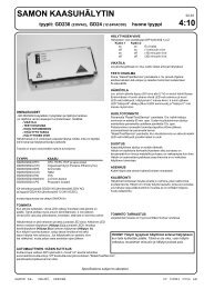
IntroductionApplicationThe <strong>controller</strong> is used for capacity regulation of compressors orcondensers in small refrigerating systems.Numbers of compressors and condensers can be connected, asrequired.There are eight outputs and more can be added via an externalrelay module.Advantages• Patented neutral zone regulation• Many possible combinations for compressor constellations• Sequential or cyclic operation• Possibility of suction pressure optimisation via the data communicationRegulationRegulation is based on signals from one pressure transmitter forthe compressor regulation and one pressure transmitter for thecondenser regulation plus one temperature sensor for the airtemperature before the condenser.The two pressure transmitters can be replaced by twotemperature sensors when regulation has to be carried out onbrine systems.• Pressure regulation P0 (pack)• Temperature regulation Sx (chiller)• Pressure regulation Pc (pack / chiller)• Pressure regulation with variable reference (Sc3)Functions• Relays for compressor and condenser regulation• Voltage output for capacity regulation of condenser• Status inputs. An interrupted signal indicates that the safetycircuit has been activated and the respective circuit stopped• Contact inputs for indication of alarms• Contact inputs for displacement of references or for indication ofalarms• Alarm relay• External start/stop of regulation• Possibility of data communicationOperationAll operation takes place either via data communication or viaconnection of a display type EKA 164 or EKA 165.CombinationsThe <strong>controller</strong> has ten relay outputs two of which have beenreserved for the alarm function and for the ”AKD start/stop”function.For a start relays are reserved for compressor capacities startingfrom DO1, DO2, etc.The remaining relays up to and including DO8 will then beavailable for fans. If more are required, one or more relay modulestype <strong>EKC</strong> 331 with max. eight steps can be connected. The signalsto these modules are to be taken from the <strong>controller</strong>’s analogoutput. Another solution could be that the fan speed is controlledvia the analog output and a frequency converter.If the alarm function and the ”AKD start/stop” function are left out,all ten relay outputs may be used for compressors and fans (butmax. eight for compressors and max. eight fans).Compressors and unloaders canbe combined in various ways. Cf.survey on page 11. <strong>Manual</strong> RS8DD602 © Danfoss 10-2006 <strong>EKC</strong> <strong>531D1</strong>
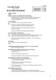
Function<strong>Capacity</strong> regulationThe cut-in capacity is controlled by signals from the connectedpressure transmitter/temperature sensor and the set reference.Outside the reference a neutral zone is set where the capacity willneither be cut in nor out.Outside the neutral zone (in the hatched areas named +zone and-zone) the capacity will be cut in or out if the regulation registers achange of pressure “away” from the neutral zone. Cutin and cutoutwill take place with the set time delays.If the pressure however “approaches” the neutral zone, the <strong>controller</strong>will make no changes of the cut-in capacity.If regulation takes place outside the hatched area (named ++zoneand --zone), changes of the cut-in capacity will occur somewhatfaster than if it were in the hatched area.Cutin of steps can be defined for either sequential, cyclic, binary or"mix & match" operation.Sequential (first in - last out)The relays are here cut in in sequence – first relay number 1, then2, etc.Cutout takes place in the opposite sequence, i.e. the last cut-inrelay will be cut out first.Cyclic (first in - first out)The relays are coupled here so that the operating time of theindividual relays will become equalised.At each cutin the regulation scans the individual relays’ timer,cutting in the relay with least time on it.At each cutout a similar thing happens. Here the relay is cut outthat has most hours on the timer.Rx = random relayh = number of hoursIf capacity regulation is carried out on two compressors with oneunloader each, the following function can be used:Relays 1 and 3 are connected to the compressor motor.Relays 2 and 4 are connected to the unloaders.Relays 1 and 3 will operate in such a way that the operating timefor the two relays will become equalised.C = compressor, L = Unloader<strong>EKC</strong> <strong>531D1</strong> <strong>Manual</strong> RS8DD602 © Danfoss 10-2006
Suvey of functionsThe total function content is shown below – not all functions are present at the sametime. The setting of o61 determines which functions are present.The menu overview on page 14 shows the various functions and settings.ParameterParameter by operation viadata communicationFunctionNormal displayIf the two displays are mounted:P0 °C or P0 bP0 will be shown on EKA 165 (the one with buttons)Pc °C or Pc bPc will be shown on EKA 163. Both readouts will be in temperature or in bar.Compressor regulation referenceCompressor controlP0 setpointr23 P0Set Point °C / P0Set Point bRegulation is based on the set value plus an offset, if applicable. An offset can be createdfrom night setback r13 and/or from a system units override function.Offsetr13 Night offsetThe set reference may be displaced with a fixed value when a signal is received at theDI4 input or from the function "Night setback" (r27).(Cf. also Definition of DI4 input).Night setbackr27 NightSetBackOFF: No change of the referenceON: Offset value forms part of the referenceReferencer24 P0 ref. °C / P0 ref. bThe regulation reference is shown hereSet point limitationWith these settings the setpoint can only be set between the two values.(This also apply if regulation with displacements of the reference).Max. permissible setpoint value. r25 P0RefMax °C / P0RefMax bMin. permissible setpoint value. r26 P0RefMin °C / P0RefMin bNeutral zoneThere is a neutral zone around the reference. See also page 3.Correction of pressure measurementAn offset adjustment of the registered pressure can be made.UnitHere you can select whether the display is to indicate temperatures in °C or °F (pressurein bar or psig).0: Will give °C / bar1: Will give °F / psigStart/stop of refrigerationWith this setting the refrigeration can be started and stopped. Start/stop of refrigerationmay also be performed with an external contact function connected to the inputnamed “ON input”. (The input must be wired).Condenser regulation referencePc setpointRegulation is based on the set value plus an offset, if applicable. An offset can be createdvia the “r34” function and/or from a system units override function.OffsetThe set reference may be displaced with a fixed value when a signal is received at theDI5 input. (Cf. also Definition of DI5 input).Pc reference variation. See also page 22Regulation with setting 1 (or 2 if the reference is to vary with the outdoor temperature)will give the best regulation if the system is in balance. But if a lot of condensersteps are cut in and out and the compressor capacity often becomes low, it will benecessary to select setting 3 instead (or 4, if there is regulation with the outdoor temperature).(Settings 3 and 4 will generally be preferable if a Pc-offset at max. compressorcapacity can be accepted).1: No change of the reference. Regulation based on set setpoint. And offset with theDI5 function is allowed.2: Outdoor temperature forms part of the reference. The outdoor temperature ismeasured with Sc3. When the outdoor temperature drops one degree, the referenceis lowered one degree.Here is offset with the DI5 function not allowed. At DI5 signal the reference willchange to the set setpoint.Setting 1 and 2 operate with a PI regulation, but if the system is unstable and the PIregulation not satisfactory the I element may be left out, so that the <strong>controller</strong> will bewith P regulation only.3: As 1, but with P regulation (xp-band)4: As 2, but with P regulation (xp-band)r01r04r05r12r28r34r33Neutral zoneAdjustSensor(In AKM only bar or °C is used, whateverthe setting)Main SwitchCondenser controlPcSet Point °C / PcSet Point bPcRefOffsetPc mode <strong>Manual</strong> RS8DD602 © Danfoss 10-2006 <strong>EKC</strong> <strong>531D1</strong>
Condenser referencer29 Pc ref. °C / Pc ref. bThe regulation reference is shown here.Set point limitationWith these settings the setpoint can only be set between the two values.(This also applies to regulations where the Xp band lies above the reference).Max. permissible setpoint value. r30 PcRefMax °C / PcRefMax bMin. permissible setpoint value. r31 PcRefMin °C / PcRefMin bCorrection of pressure measurementr32 AdjustSensorAn offset adjustment of the registered pressure can be made.Dimensioning temperature Dim tmr35 Dim tm KThe mean temperature difference across the condenser at maximum load (tm differenceat max. load). This is the temperature difference between the air and condensingtemperature.Dimensioning temperature Min tmr56 Min tm KThe mean temperature difference across the condenser at the lowest relevantcompressor capacity (tm difference at min. load). This is the temperature differencebetween the air and condensing temperature.Reading your P0r57 P0°C / P0 bThis is where you can see the actual pressure that is being measured by the pressuretransmitter.The value is part of the regulation, since the regulation signal for capacity regulationoriginates from the pressure transmitter.The value is part of the frost protection regulation, since the regulation signal forcapacity regulation originates from the temperature sensor.Reading your T0r58 Cmp.CtrlSensThis is where you can see the actual pressure being measured by the sensor chosenfor capacity regulation (the sensor is defined in o81). The value is displayed in °C.Compressor capacityCompressor pack config.Running timeTo prevent frequent start/stop, values have to be set for how the relays are to cut inand out.Min. ON time for relays.c01 Min.ON time(The time is not used if the relay cuts an unloader in or out).Min. time period between cutin of same relay.c07 MinRecyTime(The time is not used if the relay cuts an unloader in or out).Setting for neutral zone regulationRegulation band over the neutral zonen c10 + Zone k / + Zone bTime delay between step cut-ins in the regulation band over the neutral zone c11 + Zone mTime delay between step cut-ins in the regulation band over the "+Zone band". c12 + + Zone mRegulation band under the neutral zone c13 - Zone k / - Zone bTime delay between step cut-outs in the regulation band under the neutral zone c14 - Zone mTime delay between step cut-outs in the regulation band under the "-Zone band" c15 - - Zone mPump down limitc33 PumpDownLim.The factory setting for this function is OFF.Activate by setting a value corresponding to pressure under the zone and over the P0min. limit.The function keeps the last capacity step going until the pressure comes down to thepump down limit. When this value is reached the last compressor will cut out.Do not reconnect capacity until the pressure is once more above the neutral zone.Compressor configurationc16 Compr modeThis setting only applies if “061” is set to “1” or “2”.Here you set the predefined combination of number of compressors and any unloaders.1 = One compressor, 2 = two compressors, 3 = three, 4 = four.5 = One compressor + one unloader. 6 = One compressor + two unloaders.For 7 to 26: See survey on page 11If the compressors are of different sizes the setting must be selected to either 4 or 0.At pos. 0 it is up to you to determine which relays have to be drawn on at each of therequired capacity steps.Selection of coupling mode (See also the overview page 11)c08 Step mode1. Sequential: First relay 1 cuts in, then relay 2, etc. Cutout takes place in the oppositesequence. (”First in, last out”).2. Cyclic: An automatic operating time equalisation is arranged here, so that all stepswith motor connection will have the same operating time3. Binary and cyclic (only for four compressors with "c16" set to 4.Unloaders’ cutin and cutout modeThe relays for unloaders can be set to switch on when more capacity is required (setting= 0), or they can switch off when more capacity is called for (setting = 1).c09 Unloader(switch on = 0)(switch off = 1)<strong>EKC</strong> <strong>531D1</strong> <strong>Manual</strong> RS8DD602 © Danfoss 10-2006
Mix and Match step 1.c17 M&M Step 1This function cuts the relay in and out depending on the definitions in "c17" to"c28".(“c17” to “c28” only used, if “o61” selected to “3” or "4"). (In Mix and Match couplings thesettings “c08” and c09" are not used).Step 1Here in c17 set the relays to be ON at step 1.Setting takes place with a numerical value representing the combination of relays. Seethe survey page 11. Proceed by defining steps two, three, etc.The definition ends at the first c18 - c28 which is set to “0”.The time delays “c01” and “c07” belong to the individual relay outputs. If a relay outputis captured by the time delay, a changeover from one step to another will only takeplace when all the relay outputs concerned have been released. The time delay willnot interfere with a relay which is ON in two successive couplings. If a compressordrops out there will be an alarm. The regulation will continue as emergency operation,as if the compressor were present.Step 2. Here you also set a value between 1 and 15. Here in c18 the value will indicate c18 M&M Step 2which relays have to be ON at step 2.Step 3. etc. c19 M&M Step 34. Etc. c20 M&M Step 45. c21 M&M Step 56. c22 M&M Step 67. c23 M&M Step 78. c24 M&M Step 89. c25 M&M Step 910. c26 M&M Step 1011. c27 M&M Step 1112. c28 M&M Step 12<strong>Manual</strong> control of compressor capacityc31 CmpManCap%This sets the capacity that is to be cut in when switching to manual control.(c01 and c07 will still apply)<strong>Manual</strong> controlc32 CmpManCap<strong>Manual</strong> control of the compressor capacity is enabled here.When set to ON, the capacity that is set in “c31” is cut in.- - - - Comp. Cap %Read cut-in compressor capacityActuel zone state:0=off. 1= --zone. 2=-zone. 3=Neutralzone.4=+zone. 5=++zoneCondenser capacityDefinition of condenser and number of fansc29 Fan modeHere you set the number of fan steps with which regulation has to be carried out (butmax. eight).1-8: All fans are cut in and out with relays. The first vacant relay number is assigned tofan 1, the next to number 2, etc. Steps after DO8 must be executed through connectionof a relay module type <strong>EKC</strong> 331 to the analog output. Cf. drawing on page 12.9: All fans controlled via the analog output and a frequency converter.10: Not used11-18: Total number of fan relays (as 1-8), but here the starting sequence is alteredafter each time all fans are stopped.Read temperature at sensor Sc3 u44 Sc3 tempRead temperature at sensor Sc4 (sensor is only used for monitoring) u45 Sc4 temp- - - - Fan Cap %Read cut-in condenser capacityRegulation parameters for the condenser regulationProportional band xp (P = 100/Xp)If the Xp value is increased, the regulation becomes steadiern04 Xp KI: Integration time TnIf the Tn value is increased, the regulation becomes steadier<strong>Manual</strong> control of condenser capacityThis sets the capacity that is to be cut in when switching to manual control.<strong>Manual</strong> control<strong>Manual</strong> control of the condenser capacity is enabled here.When set to ON, the capacity that is specified in “n52” is cut in.Speed control start valueSpeed control will only be activated when the capacity requirement reaches thisvalue.Speed control stop valueSpeed control will be stopped when the capacity requirement falls below this value. <strong>Manual</strong> RS8DD602 © Danfoss 10-2006 <strong>EKC</strong> <strong>531D1</strong>n05n52n53n54n55Tn sFanManCap%FanManCapStartSpeedMinSpeed
AlarmThe <strong>controller</strong> can give alarm in different situations. When there is an alarm the lightemittingdiodes (LED) will flash on the display and the alarm relay will cut in.(In <strong>EKC</strong> <strong>531D1</strong> the alarm relay may be used for a fan, if required).P0 min. (Alarm and safety function, see also page 20.)Here you set when the alarm at too low suction pressure is to enter into effect. Thevalue is set as an absolute value.Alarm delay P0 alarmThe time delay is set in minutes. At min. setting the alarm is cancelled.Pc max. (Alarm and safety function, see also page 20.)Here you set when the alarm at too high condensing pressure is to enter into effect.The value is set as an absolute value.Alarm delay Pc alarmThe time delay is set in minutes. At min. setting the alarm is cancelled.Alarm delay DI1 (an interrupted input will give alarm).The time delay is set in seconds. At max. setting the alarm is cancelled.Alarm delay DI2 (an interrupted input will give alarm).The time delay is set in seconds. At max. setting the alarm is cancelled.Alarm delay DI3 (an interrupted input will give alarm).The time delay is set in seconds. At max. setting the alarm is cancelled.Alarm limit for high temperature of the “Saux1” sensorWith setting = Off the alarm has been opted out.Alarm delay from "Saux1" (A32)If the limit value is exceeded, a timer function will commence. The alarm will not becomeactive until the set time delay has been passed. The time delay is set in minutes.Give the top button a brief push to zeroset the alarm and to have the message shownon the display.A11A44A30A45A27A28A29A32A03Alarm settingsMin. P0. bP0AlrmDelayMax. Pc. bPcAlrmDelayDI1AlrmDelayDI2AlrmDelayDI3AlrmDelaySaux1 highAlarm delayReset alarmThe function zerosets all alarms whenset in pos. ON.With data communication the importanceof the individual alarms can bedefined. Setting is carried out in the“Alarm destinations” menu.MiscellaneousChoice of applicationThe regulator can be configured in various ways. The use that is required out of thefour uses available is set here. The functions for the four uses can be viewed on page14. This menu must be set as the first of all menus, as it enables the associated settings tobe set.1. Temperature signal and "c16" mode2: Pressure signal and "c16" mode3. Temperature signal and M&M mode4. Pressure signal and M&M modeSensor type (Sc3, Sc4 and "Saux1") (see also overview page 21)Normally a Pt1000 sensor with great signal accuracy is used for temperature measurementand AKS 32R for pressure measurement. But a PTC sensor may also be used (r25= 1000) in special situations.All temperature sensors must be of the same kind.In brine cooling the pressure measurements are replaced by temperature measurements.The following settings are possible:0=PT1000. 1=PTC1000. 2=PT1000 on sensors and on Po. 3=PTC1000 on sensors andon Po. 4=PT1000 on sensors and on Pc. 5=PTC1000 on sensors and on Pc. 6=PT1000on sensors, on Po and on Pc. 7=PTC1000 on sensors, on Po and on Pc.(If a temperature sensor is mounted on P0 or Pc, the respective settings in o20, 21, 47and 48 will not be required).Definition of the signal to the P0 regulation when temperature signal:If no frost protection is required, connect the temperature sensor to the P0 input.If frost protection is required, you must connect a pressure transmitter and the temperaturesensor must be connected to the Saux or S4 input.0. Pressure transmitter AKS32R on P01. Temperature inlet Saux2. Temperature inlet S4(P0 min. function (A11) will not be affected by the definition)Display connectionThis is where you define the type of display that is connected to the <strong>controller</strong>Off: EKA 164On: EKA 165. The extended display with LEDs.o61o06o81o82MiscellaneousThis setting cannot be made via datacommunication. It must be set directlyon the <strong>controller</strong>.Sensor typeCtrl.SensorRead temperature at sensor "Saux1" o49 Saux1 temp<strong>EKC</strong> <strong>531D1</strong> <strong>Manual</strong> RS8DD602 © Danfoss 10-2006
Pressure transmitter’s working rangeDepending on the pressure, a pressure transmitter with a given working range isused. This working range must be set in the <strong>controller</strong> (e.g.: -1 to 12 barThe values must be set in bar if display in °C has been selected. And in psig, if °F hasbeen selected.P0-Min. value o20 P0MinTrsPresP0-Max. value o21 P0MaxTrsPresPc-Min. value o47 PcMinTrsPresPc-Max. value o48 PcMaxTrsPresUse of DI1 inputo78 Di1 controlThe digital input can be connected to a contact function, and the contact can now beused for one of the following functions:Setting / function:0: DI input not used1: Fan alarm when contact cuts out. Alarm "A34" is given.2: Alarm function when the contact cuts out. Alarm “A28” is given.There is time delay for the alarm. Setting in "A27".Use of DI4 inputo22 Di4 controlThe digital input can be connected to a contact function, and the contact can now beused for one of the following functions:Setting / function:0: DI input not used1: Regulation reference P0 displaced when contact is cut in2: Alarm function when the contact cuts out. Alarm “A31” is given. There is no timedelay.Use of DI5 inputThe digital input can be connected to a contact function, and the contact can now beused for one of the following functions:Setting / function:0: DI input not used1: Regulation reference Pc displaced when contact is cut in2: Alarm function when the contact cuts out. Alarm “A32” is given. There is no timedelayo37 Di5 controlOperating hoursThe operating hours for the compressor relays can be read and set in the followingmenus. The read value is multiplied by 1000 to obtain the number of hours (f.ex.shows 2.1 for 2100 hours). On reaching 99.9 hours the counter stops and must now bereset to, say, 0. There will be no alarm or error message for counter overflow.Value for relay number 1 to 4 o23-o26Value for relay number 5 to 8 o50-o53Refrigerant settingo30Before refrigeration is started, the refrigeration must be defined. You may choosebetween the following refrigerants:1=R12. 2=R22. 3=R134a. 4=R502. 5=R717. 6=R13. 7=R13b1. 8=R23. 9=R500.10=R503. 11=R114. 12=R142b. 13=User defined. 14=R32. 15=R227. 16=R401A.17=R507. 18=R402A. 19=R404A. 20=R407C. 21=R407A. 22=R407B. 23=R410A.24=R170. 25=R290. 26=R600. 27=R600a. 28=R744. 29=R1270. 30=R417A.31=R422A.Warning: Wrong selection of refrigerant may cause damage to the compressor.Other refrigerants: Select setting 13 here, and subsequently three factors have to beset – fac1, fac2 and fac3 – via AKM.<strong>Manual</strong> control (stopped regulation only)From this menu the relays can be cut in and out manually. 0 gives no override, but anumber between 1 and 10 will cut in a belonging relay. 1 will cut in relay number 1, 2relay 2, etc.11-18 will produce voltage on the analog output. In this way the relays on the externalrelay module can be activated. Setting 11 will give a voltage of 1.25 V, setting 12will give 2.5 V, etc.Frequencyo12Set the net frequency.o18 - - -If the values are to be set from theAKM programme, they must be set inbar.(In the AKM display the hour numberhas not been multiplied)DO1 run hour.....DO4 run hourDO5 run hour ......DO8 run hourRefrigerant50 / 60 Hz(50=0, 60=1) <strong>Manual</strong> RS8DD602 © Danfoss 10-2006 <strong>EKC</strong> <strong>531D1</strong>
AddressIf the <strong>controller</strong> is built into a network with data communication, it must have anaddress, and the master gateway of the data communication must then know thisaddress.These settings can only be made when a data communication module has beenmounted in the <strong>controller</strong> and the installation of the data communication cable hasbeen completed.This installation is mentioned in a separate document “RC8AC”.The address is set between 1 and 240 (gateway determined)The address is sent to the gateway when the menu is set in pos. ONAccess codeIf the settings in the <strong>controller</strong> are to be protected by a numerical code, you can set anumerical value between 0 and 100. If not, you can cancel the function with settingOFF.o03o04o05Following installation of a data communicationmodule, the <strong>controller</strong> canbe operated on a par with the other<strong>controller</strong>s in ADAP-KOOL® refrigerationcontrols.Special settingsOutputs DO9 and DO10 are normally used for the ”AKD start/stop” function and for the alarmfunction, but they may be redefined in special cases.DO9 function:o75 DO9 function0: AKD Start/stop1: Inject-on function (see drawing below)2: Boost ready function (see drawing below)3: Fan relayDO10 function:o76 DO10 function0: Alarm relay1: Fan relayStatus on the digital inputsThe signal on the DI inputs can be read in the following menus:Status on DI 1 u10 DI 1 StatusStatus on DI 2 u37 DI 2 StatusStatus on DI 3 u87 DI 3 StatusStatus on DI 4 u88 DI 4 StatusStatus on DI 5 u89 DI 5 StatusConfiguration settings (compressor and fan definitions, coupling mode and refrigerant) can only take place when regulation is stopped.DO9 function:Inject-on functionDO9 is here used for the Inject ON function. Here all the electronic expansion valves are closed when all the compressors are stoppedand P0 > +Zone.Wiring is carried out as shown below.The function may however also be generated via data communication. In this way the relay output is made available for otherapplications.Boost ready functionIf two <strong>controller</strong>s are to capacity regulate the high-temperature part and the low-temperature part, respectively, they must beconnected in such a way that low-temperature regulation cannot be started until the high-temperature part is operating. The signalcan be taken from DO9 of one <strong>controller</strong> and received on the ON inpout of the other <strong>controller</strong>.Example:<strong>EKC</strong> <strong>531D1</strong> <strong>Manual</strong> RS8DD602 © Danfoss 10-2006
Operating statusThe <strong>controller</strong> goes through some regulating situations where it is just waiting for the nextpoint of the regulation. To make these “why is nothing happening” situations visible, you cansee an operating status on the display. Push briefly (1s) the upper button. If there is a statuscode, it will be shown on the display. The individual status codes have the following meanings<strong>EKC</strong> state(0 = regulation)S2: When the relay is operated, it must be activated for min. x minutes (cf. c01) 2S5: Renewed cutin of the same relay must not take place more often than every x minutes (cf. 5c07)S8: The next relay must not cut in until x minutes have elapsed (cf.c11-c12) 8S9: The next relay must not cut out until x minutes have elapsed (cf. c14-c15) 9S10: Regulation stopped with the internal og external start/stop 10S25: <strong>Manual</strong> regulation of outputs 25S34: Safety cutout. Setting A30 is exceeded 34Alarm messagesAlarms "Destinations"A2: Low P0 A02 Low P0 alarmA11: No refrigerant has been selected (cf. o30) A11 No RFG SelA17: High Pc A17 Hi Pc alarmA19 ....A26: Compr. fault. Interupted signal on input "DO 1" /2/3/4/5/6/7/8A19..... A26 Comp._faultA27: High temperature alarm for sensor "Saux1" A27 Saux1 highA28 .... A32: External alarm. Interrupted signal on input "DI1" /2/3/4/5A28..... A32 DI_ AlarmA34: Fan alarm. There is signal on DI1 input A34 Fan faultA45: Regulation stopped with setting or with external switch A45 Stand byE1: Error in the <strong>controller</strong> E1 Ctrl. faultE2: Control signal outside the range (short-circuited/interrupted) E2 Out of range10 <strong>Manual</strong> RS8DD602 © Danfoss 10-2006 <strong>EKC</strong> <strong>531D1</strong>
Compressor configuration when o61 =1 or 2 (This is where you can choose between the options shown.)Setting "c16" will define the configuration.Setting "c08" will define coupling mode.Compressor connectionsRelay no.Set"C16"toCouplingmodeSet"C08"to<strong>Capacity</strong> stepAll capacity steps are presumed to be identical.The only exception is the settings c16 = 4and 21 to 26.Coupling modeCoupling mode 1 = sequential operation.Coupling mode 2 = cyclic operation.Coupling mode 3 = cyclic and binaryoperation where the compressor capacitiesare, as follows:1: 9%2: 18%3: 36%4: 36%There is cyclic coupling at 3 and 4, and binaryon 1, 2 and 3/4.(for c16=4 only)CouplingsWhen there is cyclic operation andconnections with unloaders there will in somecapacity cutins and cutouts be overlappingswhere the unloaders from either onecompressor or another may be active.In such cases the unloaders on the compressorwith the lowest number of hours will be cut in,and the others cut out.The changeover will take place at 6-secondintervals.Equalised operationWhen c16 = 21 to 26, compressor 1 +belonging unloader must have the samecapacity as each of the subsequentcompressors. The unloading function willequalise the cut-in capacity when thesubsequent compressors are cut in and out.Compressor 1 will always be operating.Compressor configuration when o61 = 3 or 4 (This is where you must define yourself how the relays are to be activated.)Survey of relays in Mix and Match operationCalculationRelay no.Combination of relays that must be cut invalue1 1 1 1 1 1 1 1 1 12 2 2 2 2 2 2 2 2 23 4 4 4 4 4 4 4 4 44 8 8 8 8 8 8 8 8 8The sum of 1-8 is the settingvalue for each1 2 3 4 5 6 7 8 9 10 11 12 13 14 15stepExample 1<strong>Capacity</strong> stepsSettings:c17 to 1c18 to 2c19 to 3c20 to 4c21 to 5c22 to 6c23 to 7Example 2If capacity step 1 has to cut in relay number 3 only, you must set c17 to 4.If capacity step 2 has to cut in relay number 4 only, you must set c18 to 8.If capacity step 3 has to cut in relay numbers 3 and 4, you must set c19 to 12.Continue with a setting for c20 etc. until all capacity steps have been defined.<strong>EKC</strong> <strong>531D1</strong> <strong>Manual</strong> RS8DD602 © Danfoss 10-2006 11
Condenser couplingsWhen the compressor relays have been established the turncomes to the fan relays.The first vacant relay (DO1-DO8) will become the first fan relay.It will be followed by the subsequent relays. If more relays arerequired than the vacant DO relays, a relay module can beconnected to the analog output. The function is, as follows:If there are up to four external fans on an <strong>EKC</strong> 331:If there are more than four external fans on two <strong>EKC</strong> 331 units:1. 2.Output signal from <strong>EKC</strong> <strong>531D1</strong>In <strong>EKC</strong> 331 the voltage range must be set to 0-5 V (“o10” = 6).In <strong>EKC</strong> 331 the number of steps must be set to 4 (“o19” = 4) (also whenfewer fans are connected).Output signal from <strong>EKC</strong> <strong>531D1</strong>In the first <strong>EKC</strong> 331, set 0-5 V (“o10” = 6).In the second <strong>EKC</strong> 331, set 5-10 V (“o10” = 7).In both <strong>EKC</strong>’s the number of steps must be set to 4 (“o19” = 4) (also whenfewer fans are connected to the second <strong>EKC</strong>).ConnectionConnectionAlternating start-up of fans (only if c29 is 11 to 18)The fans can be defined to start alternately when they have allbeen stopped.The first time regulation is started, fan 1 will be started first – theregulation determines whether additional fans will be started.After the next time all fans are stopped, fan 2 will be the first to bestarted, and so on.Fan 1 will again be the first fan to be started when the rotation hasbeen through the total number of fans.If there is more than one fan on an <strong>EKC</strong> 331, it will not be possibleto start the other fans first. Here, the fan with the lowest voltagestep will always be the one which is started first.If the entire condenser capacity is to be controlled by afrequency converter, <strong>EKC</strong> <strong>531D1</strong> must send an analogsignal about the required capacity (“c29” = 9).The signal varies from 0 to 10 V. Signal and capacityhave the following context.12 <strong>Manual</strong> RS8DD602 © Danfoss 10-2006 <strong>EKC</strong> <strong>531D1</strong>
OperationData communicationIf the <strong>controller</strong> is extended with data communication, the operationcan be performed from a system unit. The parameter namesfor the functions can be viewed in the right-hand column onpages 4–10.The importance of the alarms that are sent can be defined withthe setting: 1 (High), 2 (Medium), 3 (Low) or 0 (No alarm).Operation via external displayThe values will be shown with three digits, and with a setting youcan determine whether the pressures are to be shown in °C or inbar. Or whether the temperature is to be shown in °F or in psig.There are three options for the display.EKA 165To operate the <strong>controller</strong> and view the evaporation pressure.If the lowermost key is pressed, the condensation pressure willbe shown briefly in the display. (If regulation is based only on thecondensation pressure, the display will always show Pc).You can connect thisdisplay to the <strong>EKC</strong><strong>531D1</strong> with softwareversion 1.3 or later.During normal operation the light-emitting diodes in the displaywill indicate where regulation is taking place.Highest + second highest : ++ZoneSecond highest : +Zone"None" : Neutral zoneSecond lowest : -ZoneLowest+ second lowest : - - ZoneEKA 165EKA 163EKA 164The other LEDs on the display will show the functions that areactive:• Relays for compressors• Relays for fans• Input signals for the digital inputs• The optimisation LED will light up when the reference is 2 K ormore over the set point.EKA 163If the condensation pressure is to be shown constantly, a displaywithout operating keys can be connected.EKA 164To operate the <strong>controller</strong> and view the evaporation pressure.If the lowermost key is pressed, the condensation pressure will beshown briefly in the display.Like the EKA 165, the LEDs in the display will show where theregulation is located.The buttons on the displayWhen you want to change a setting, the upper and the lowerbuttons will give you a higher or lower value depending on thebutton you are pushing. But before you change the value, youmust have access to the menu. You obtain this by pushing theupper button for a couple of seconds - you will then enter thecolumn with parameter codes. Find the parameter code you wantto change and push the mittle button. When you have changedthe value, save the new value by once more pushing the mittlebutton.Or short:1. Push the upper button (long push) until a parameter is shown2. Push one of the buttons and find the parameter you want tochange3. Push the mittle button until the setting value is shown4. Push one of the buttons and select the new value5. Push the mittle button again to conclude the setting( A brief pushing wil show the active alarm codes. See page 17.)<strong>EKC</strong> <strong>531D1</strong> <strong>Manual</strong> RS8DD602 © Danfoss 10-2006 13
Menu surveySequence1. o61 must be set as the first parameter. This parameter determines which of the four operating interfaces (application mode) areactivated. This must be set via the display keys. It cannot be set via data communication. (Active functions are shown below in shadedfields.)2. Quick- startTo get the system up and running quickly so that cooling can be commenced, start it by setting the following parameters (these parameterscan only be set when the regulation is stopped, r12=0):r23, r28 and then either (c08, c09 and c16) or (c17 to 28) – continue with c29, o06, o30, o75, o76, o81 and finally r12=1.3. Once the regulation is under way, you can go through the other parameters and adjust them in situ.SW: 1.3xFunctionParametero61 = Min. Max. Factorysetting1 2 3 4Normal displayShows P0 in EKA 165 (display with buttons) - °C P °C P °C / barShows Pc in EKA 163 - °C P °C P °C / barP0 referenceNeutral zone r01 0.1°C / 0.1 bar 20°C /5.0 bar 4.0°C / 0.4 barCorrection of signal from P0 sensor r04 -50°C /-5.0 bar 50°C / 5.0 bar 0.0Select unit (0=bar and °C, 1=Psig and °F) r05 0 1 0Start/Stop of regulation r12 OFF ON OFFReference offset for P0 (see also r27) r13 -50°C / -5.0 bar 50°C / 5.0 bar 0.0Set regulation setpoint for P0 r23 -99°C / -1 bar 30°C / 60.0 bar 0.0°C / 3.5 barShows total P0 reference( r23 + various displacements)r24°C / barLimitation: P0 reference max. value(also applies to regulation with reference displacement)r25 -99°C / -1.0 bar 30°C / 60.0 bar 30.0°C / 40.0 barLimitation: P0 referencen min. value(also applies to regulation with reference displacement)r26 -99°C / -1.0 bar 30°C / 40.0 bar -99.9°C / -1.0 barDisplacement of P0 (ON=active “r13”) r27 OFF ON OFFPc referenceSet regulation setpoint for Pc r28 -25°C / 0.0 bar 75°C / 60.0 bar 35°C / 15.0 barShows total Pc reference r29 °C / barLimitation: Pc referencen max. value r30 -99.9°C / -0.0 bar 99.9°C / 60.0 bar 55.0°C / 60.0 barLimitation: Pc referencen min. value r31 -99.9°C / 0.0 bar 99.9°C / 60.0 bar -99.9°C / 0.0 barCorrection of signal from Pc sensor r32 -50°C / -5.0 bar 50°C / 5.0 bar 0.0Pc reference variation.1 and 2 are PI-regulation1: Fixed reference. “r28” is used2: Variable reference. Outdoor temperature (Sc3) includedin the referencer33 1 4 13: As 1, but with P-regulation (Xp-band)4: As 2, but with P-regulation (Xp-band)Reference offset for Pc r34 -50°C / -5.0 bar 50°C / 5.0 bar 0.0The mean temperature difference across the condenser atmaximum load (dim tm K)r35 3.0 50.0 10.0The mean temperature difference across the condenser atthe lowest relevant compressor capacity (min tm K)r56 3.0 50.0 8.0This is where you can see the actual pressure (P0) that isbeing measured by the pressure transmitter.r57°C / barThis is where you can see the actual pressure (T0) that ispart of the regulation. From the sensor which is defined r58 °Cin “o81”<strong>Capacity</strong>Min. ON time for relays c01 0 min 30 min. 0Min. time period between cutins of same relay c07 0 min. 60 min 4Definition of regulation mode1: Sequential (step mode / FILO)2: Cyclic (step mode / FIFO)c08 1 3 13: Binary and cyclicIf a regulation mode with unloaders is selected, the relaymust be defined to:0: Cut in when more capacity is required1: Cut out when more capacity is requiredc09 0 1 0To be continued14 <strong>Manual</strong> RS8DD602 © Danfoss 10-2006 <strong>EKC</strong> <strong>531D1</strong>
Regulation parameter for + Zone c10 0.1 K / 0.1 bar 20 K / 2.0 bar 4.0 / 0.4 barRegulation parameter for + Zone c11 0.1 min 60 min 4.0Regulation parameter for ++ Zone c12 0.1 min. 20 min 2.0Regulation parameter for - Zone c13 0.1 K / 0.1 bar 20 K / 2.0 bar 4.0 / 0.3 barRegulation parameter for - Zone c14 0.1 min. 60 min 1.0Regulation parameter for - - Zone c15 0.02 min. 20 min 0.5Definition of compressor connections.See options on page 11.c16 1 26 0Following "c17" to "c28" is another way to define compressorwthan with "c16".. A code will then have to be set forthe relays that are to be ON at the different steps:c17 0 15 0Step 1 (M&M operation)Step 2 (M&M operation) c18 0 15 0Step 3 (M&M operation) c19 0 15 0Step 4 (M&M operation) c20 0 15 0Step 5 (M&M operation) c21 0 15 0Step 6 (M&M operation) c22 0 15 0Step 7 (M&M operation) c23 0 15 0Step 8 (M&M operation) c24 0 15 0Step 9 (M&M operation) c25 0 15 0Step 10 (M&M operation) c26 0 15 0Step 11 (M&M operation) c27 0 15 0Step 12 (M&M operation) c28 0 15 0Definition of condenser:1-8: Total number of fan relays or voltage step on thevoltage output9: Only via analog output and start of frequency converterc29 0/OFF 18 010: Not used11- 18: Total number of fan relays which are to be connectedwith alternating start-up.Cut in compressor capacity with manual control. See also“c32”c31 0% 100% 0<strong>Manual</strong> control of compressor capacity (when ON, thevalue in “c31” will be used)c32 OFF ON OFFPump down limit. Limit value where the last compressoris cut out.c33 -99.9°C / -1.0 bar 100°C / 60 bar 100°C / 60 barProportinal band Xp for (P= 100/Xp) condenser regulation n04 0.2 K / 0.2 bar 40.0 K / 10.0 bar 10.0 K / 3.0 barI: Integration time Tn for condenser regulation n05 30 s 600 s 150Cutin condenser capacity with manual control. See also“n53”n52 0% 100% 0<strong>Manual</strong> control of condenser capacity (when ON, thevalue in “n52” will be used)n53 OFF ON OFFStart speed The voltage for the speed regulation is keptat 0V until the regulation requires a higher value than the n54 0% 75% 20%value set here.Min. speed. The voltage for the speed regulation switchesto 0V when the regulation requires a lower value than the n55 0% 50% 10%value set here.AlarmDelay time for a A32 alarm A03 0 min. 90 min. 0 min.Low alarm and safety limit for P0 A11 -99°C / -1.0 bar 30°C / 40 bar -40°C / 0.5 barDelay time for a DI1 alarm A27 0 min. (-1=OFF) 999 min. OFFDelay time for a DI2 alarm A28 0 min. (-1=OFF) 999 min. OFFDelay time for a DI3 alarm A29 0 min. (-1=OFF) 999 min. OFFUpper alarm and safety limit for Pc A30 -10 °C / 0.0 bar 99 °C / 60.0 bar 60.0°C / 60.0 barUpper alarm limit for sensor "Saux1" A32 1°C (0=OFF) 150°C OFFDelay time for a P0 alarm A44 0 min. (-1=OFF) 999 min. 0 min.Delay time for a Pc alarm A45 0 min. (-1=OFF) 999 min. 0 min.MiscellaneousControllers address o03* 1 990On/off switch (service-pin message) o04* - -* this setting is only possible if data communication module is mounted in the <strong>controller</strong><strong>EKC</strong> <strong>531D1</strong> <strong>Manual</strong> RS8DD602 © Danfoss 10-2006 15
Access code o05 1 (0=OFF) 100 OFFUsed sensor type for Sc3, Sc4 and "Saux1"0=PT1000, 1=PTC10002-7=variations with temperature sensor on P0 and Pc. Seeo06 0 7 (1) 0earlier in the manual.Set supply voltage frequency o12 50 Hz 60 H 0<strong>Manual</strong> control of outputs:0: No override1-10: 1 will cut in relay 1, 2 relay 2, etc.o18 0 18 011-18: Gives voltage signal on the analog output. (11gives 1.25 V, and so on in steps of 1.25 VP0 pressure transmitter’s working range - min. value o20 -1 bar 0 bar -1.0P0 pressure transmitter’s working range - max. value o21 1 bar 60 bar 12.0Use of DI4-input0=not used. 1=P0 displacement. 2=alarm function. o22 0 2 0Alarm="A31"Operating hours of relay 1 (value time 1000) o23 0.0 h 99.9 h 0.0Operating hours of relay 2 (value time 1000) o24 0.0 h 99.9 h 0.0Operating hours of relay 3 (value time 1000 o25 0.0 h 99.9 h 0.0Operating hours of relay 4 (value time 1000) o26 0.0 h 99.9 h 0.0Setting of refrigerant1=R12. 2=R22. 3=R134a. 4=R502. 5=R717. 6=R13.7=R13b1. 8=R23. 9=R500. 10=R503. 11=R114.12=R142b. 13=User defined. 14=R32. 15=R227.16=R401A. 17=R507. 18=R402A. 19=R404A. 20=R407C.o30 0 31 021=R407A. 22=R407B. 23=R410A. 24=R170. 25=R290.26=R600. 27=R600a. 28=R744. 29=R1270. 30=R417A.31=R422A.Use of DI5-input0=not used. 1=Pc displacment. 2=alarm function.o37 0 2 0Alarm="A32"Pc pressure transmitter’s working range - min. value o47 -1 bar 0 bar -1.0Pc pressure transmitter’s working range - max. value o48 1 bar 60 bar 34.0Read temperature at sensor "Saux1" o49 °COperating hours of relay 5 (value time 1000) o50 0.0 h 99.9 h 0.0Operating hours of relay 6 (value time 1000) o51 0.0 h 99.9 h 0.0Operating hours of relay 7 (value time 1000) o52 0.0 h 99.9 h 0.0Operating hours of relay 8 (value time 1000) o53 0.0 h 99.9 h 0.0Selection of application1. Temperature signal and "c16" mode2: Pressure signal and "c16" modeo61 1 2 3 4 1 4 13. Temperature signal and M&M mode4. Pressure signal and M&M modeFunction for relay output DO9:0. Start / stop of speed regulation1. Inject on signal for evaporator controlo75 0 3 02. Boost ready (at least one compressor is on)3. Start /stop of condenser fanFunction for relay output DO10:0. Alarm relayo76 0 1 01. Start / stop of condenser fanDefinition of alarm message at DI1 signal:0. Not used1. Fan failure (A34)o78 0 2 02. DI1 alarm (A28)Definition of the signal to the P0 regulation when temperaturesignal.If frost protection is required, the setting must be 1 or 2.0. Pressure transmitter AKA32R on P0o81 0 2 01. Temperature input Saux2. Temperature input S4Display connectionOff: EKA 164On: EKA 165 (extended display with light-emitting diodes)o82 Off On Off16 <strong>Manual</strong> RS8DD602 © Danfoss 10-2006 <strong>EKC</strong> <strong>531D1</strong>
ServiceStatus on DI1 inputu10Status on DI2 inputu37Read temperature at sensor "Sc3" u44 °CRead temperature at sensor "Sc4" u45 °CStatus on DI3 inputu87Status on DI4 inputu88Status on DI5 inputu89The <strong>controller</strong> can give the following messagesE1E2A2A11A17A19A20ErrormessageAlarmmessageFault in <strong>controller</strong>Regulation is outside the range, or the controlsignal is defectiveLow P0Refrigerant not selectedHigh PcDO 1 alarm. Terminal 29 is openDO 2 alarm. Terminal 30 is openMessages can be brought up on the display by briefly pressingthe uppermost key. If there is more than one alarm, they can bescrolled throughFactory settingIf you need to return to the factory-set values, it can be done inthis way:- Cut out the supply voltage to the <strong>controller</strong>- Keep the upper and the lower button depressed at the sametime as you reconnect the supply voltageA21A22A23A24A25A26A27A28A29A30A31A32A34A45S2S5S8S9S10S25S34StatusmessageDO 3 alarm. Terminal 31 is openDO 4 alarm. Terminal 32 is openDO 5 alarm. Terminal 33 is openDO 6 alarm. Terminal 34 is openDO 7 alarm. Terminal 35 is openDO 8 alarm. Terminal 36 is openRoom temperature alarm (Saux1 temp.)DI 1 alarm. Terminal 46 interruptedDI 2 alarm. Terminal 47 interruptedDI 3 alarm. Terminal 49 interruptedDI 4 alarm. Terminal 50 interruptedDI 5 alarm. Terminal 52 interruptedFan alarm. There is a signal on DI1 inputRegulation stoppedWait for “c01”Wait for “c07”Wait for “c11” or “c12”Wait for “c14” or “c15”Refrigeration stopped by the internal or externalstart/stop function<strong>Manual</strong> control of outputsSafety cutout. Setting A30 is exceeded or allsafety inputs (29-36) are openPS Info Access code is required before you have access tothe settings<strong>EKC</strong> <strong>531D1</strong> <strong>Manual</strong> RS8DD602 © Danfoss 10-2006 17
Connections3P0/Pc: AKS 32R:1 = Black = +2 = Blue = -3 = Brown = sBrine coolingAll inputs are low-voltage.All relay outputs may behigh-voltage.Necessary connectionsTerminals:1-2 Supply voltage 24 V a.c.4- 19 Relay outputs for either compressors, unloaders or fan motors22-24 Alarm relay *There is connection between 22 and 24 in alarm situationsand when the <strong>controller</strong> is dead27-28 24 V signal to start / stop of regulation27-29 24 V signal from the safety circuit DO 127-30 24 V signal from the safety circuit DO 227-31 24 V signal from the safety circuit DO 327-32 24 V signal from the safety circuit DO 427-33 24 V signal from the safety circuit DO 527-34 24 V signal from the safety circuit DO 627-35 24 V signal from the safety circuit DO 727-36 24 V signal from the safety circuit DO 857-59 Suction pressure. Voltage signal from AKS 32R **60-62 Condenser pressure. Voltage signal from AKS 32R **UnloaderIf an output is used for an unloader it isnot neccessary to wire the belongingsafety circuit.*)Relays DO9 and DO10 may in special cases be reconfigurated so that they can beused as fan relays. See also page 9.Application dependent connections20-21 AKD start/stop *The relay cutin when the frequency converter have tostart.37-38 Voltage signal to external condenser control39-41 Possibility of connecting an external display type EKA 163or display of Pc42-44 Possibility of connecting an external display type EKA 163for display of P0, or EKA 165 for operation and display ofP045-46 DI1 - Contact function for alarm signal45-47 DI2 - Contact function for alarm signal48-49 DI3 - Contact function for alarm signal48-50 DI4 - Contact function for displacement of the suctionpressure reference or for alarm signal.51-52 DI5 - Contact function for displacement of the condenserpressure reference or for alarm signal.51-53 Separate sensor Saux1. Sensor signal fra AKS 11, AKS 12 orEKS 11154-55 Out temperature (Sc3). Sensor signal from AKS 11, AKS 12or EKS 111 (mounted if r33 =2 or 4)54-56 Air temperature at condenser outlet. Sensor signal fromAKS 11, AKS 12 or EKS 111Data communication25-26 Mount only, if a data communication module has beenmounted.For ethernet communication the plug connection RJ45must be used. (LON FTT10 can also be connected in thisway.It is important that the installation of the data communicationcable be done correctly. Cf. separate literature No.RC8AC.The termination bracket is placed to the right of terminal26.**)• If the <strong>controller</strong> has to control only the comrpessor or the fans, respectively Pc and P0sensor can be dispensed• In brine systems temperature measurement at terminals 57-58 and 60-61 may beused instead of pressure measurement with AKS 32R. See also o06.18 <strong>Manual</strong> RS8DD602 © Danfoss 10-2006 <strong>EKC</strong> <strong>531D1</strong>
DataSupply voltage 24 V a.c. +/-15% 50/60 Hz, 5 VA2 pcs. Pressure transmitters type AKS 32RInput signal(temperature sensor in brine systems)3 pcs. temperature sensor input for PT 1000ohm/0°C or PTC 1000 ohm/25°C1 pcs. for Start/stop of regulation8 pcs. for monitoring of safety circuitsDigitale input fromcontact function. 3 pcs. for alarm function2 pcs. for alarm function or for displacement ofreferencesRelay output for8 pcs. SPSTcapacity regulationAC-1: 3 A (ohmic)AC-15: 2 A (inductive)"AKD start/stop" relay 1 pcs. SPSTAlarm relay1 pcs. SPDTAC-1: 6 A (ohmic)AC-15: 3 (inductive)Voltage output 0-10 V d.c.EKA 163Pc displayDisplay outputsOperation, P0 display andEKA 165(164)LEDData communicationPossible to connect a data communicationmodule0 - 55°C, during operation-40 - 70°C, during transportEnvironments20 - 80% Rh, not condensingNo shock influence / vibrationsEnclosure IP 20Weight0.4 kgMountingDIN rail or on wallTerminalsmax. 2.5 mm 2 multicoreEU Low voltage Directive and EMC demands reApprovalsCE-marking complied with.LVD-tested acc. to EN 60730-1 and EN 60730-2-9EMC-tested acc. to EN61000-6-2 and 3OrderingType Function Code no.<strong>EKC</strong> <strong>531D1</strong> <strong>Capacity</strong> <strong>controller</strong> 084B8007EKA 163B Display unit 084B8574EKA 164B Display unit with operation buttons 084B8575EKA 165Display unit with operation buttonsand light-emitting diodes for input and 084B8573outputCable for display unit 2 m, 1 pcs.084B7298Cable for display unit 6 m, 1 pcs.084B7299EKA 173 Data communication module, FTT 10 084B7092EKA 175 Data communication module, RS 485 084B7093Montage<strong>EKC</strong> <strong>531D1</strong>Pressure transmitter / temperature sensorPlease refer to catalogue RK0YG...Only for front mounting (IP 40)Only connection via plugsDisplay type EKA 163 / EKA 164Installation considerationsAccidental damage, poor installation, or site conditions, can giverise to malfunctions of the control system, and ultimately lead to aplant breakdown.Every possible safeguard is incorporated into our products toprevent this. However, a wrong installation, for example, could stillpresent problems. Electronic controls are no substitute for normal,good engineering practice.Danfoss wil not be responsible for any goods, or plant components,damaged as a result of the above defects. It is the installer'sresponsibility to check the installation thoroughly, and to fit thenecessary safety devices.Special reference is made to the necessity of signals to the<strong>controller</strong> when the compressor is stopped and to the need ofliquid receivers before the compressors.Your local Danfoss agent will be pleased to assist with furtheradvice, etc.Display type EKA 165<strong>EKC</strong> <strong>531D1</strong> <strong>Manual</strong> RS8DD602 © Danfoss 10-2006 19
Safety functionCriterion Compressor control Condenser controlP0 < P0 min (A11)0% capacity. (Min ON time (c01) overridden)No changeP0 signal failure (P0 reading < 5%) Calculated average capacity No change.Pc > Pc max. minus 3 KThe capacity changes to 2/3 of the actual 100% capacity(The "HP" LED on EKA 165 lights up) capacity. After 30 seconds it changes tohalf capacity.After a further 30 seconds there is a fullcut-out.Pc > Pc max. (A30) 0% capacity 100% capacityPc signal failure (Pc reading < 5%) No change 100% capacitySc3 signal failure (Variable reference (r33) isset to 2 or 4)Signal failure on the regulation sensor(Saux or S4. (o81))No changeThe P0 reference lowers by 5 K. At the sametime, the P0 signal becomes the regulationsensorThe variable part is omitted.Reference (r29) = Setting (r28)No change20 <strong>Manual</strong> RS8DD602 © Danfoss 10-2006 <strong>EKC</strong> <strong>531D1</strong>
OverrideThe <strong>controller</strong> contains a number of functions that can be usedtogether with the override function in the master gateway.They can therefore only be used in combination with datacommunication.Function via data communicationStop of injection when the compressor isstoppedFunctions to be used in the system unitsoverride functionAKC ONSelection of parameter in <strong>EKC</strong> 531AD1084B8007 Sw.1.3x- - - MC Inject ONNight serback Day/night control and time schedule r27 NightSetbackSuction pressure optimisationP0 optimisationSelect <strong>controller</strong> address(The parameters are found automatically anddo not become visible).<strong>EKC</strong> <strong>531D1</strong> registers the refrigeration point which handles the largest capacity (requires the lowestsuction pressure). The parameter may be logged for use in a service situation.- - - MLCSelecting sensor type and where the signal must be connectedOverview for setting o06Regulation P0-input Pc-input Sc3** Sc4 Saux Setting in o06Pack/chillerwith frost protection+ condenser AKS 32R* AKS 32RPt1000 Pt1000*** Pt1000*** 0PTC1000 PTC1000*** PTC1000*** 1Chillerwithout frost protection+ condenserPt1000Pt1000 Pt1000 Pt1000 2AKS 32RPTC1000 PTC1000 PTC1000 PTC1000 3Pack/chillerwith frost protection+ dry cooler AKS 32R*Pt1000 Pt1000 Pt1000*** Pt1000*** 4PTC1000 PTC1000 PTC1000*** PTC1000*** 5Chillerwithout frost protection+ dry coolerPt1000 Pt1000 Pt1000 Pt1000 Pt1000 6PTC1000 PTC1000 PTC1000 PTC1000 PTC1000 7*) Supplies signal to frost protection.**) Will supply signal to floating condenser regulation if it is defined in r33 (r33 = 2 or 4).***) With brine cooling where there should also be frost protection, connect the regulation sensor to either Sc4 or Saux (defined in o81).<strong>EKC</strong> <strong>531D1</strong> <strong>Manual</strong> RS8DD602 © Danfoss 10-2006 21
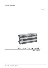
AppendixThe regulation functions are explained in more detail below.The PC referenceYou may choose between four different regulation modes.Basically 1 or 2 are recommended. But if the plant is unstable itmay become necessary to change over to 3 or 4.1. PI regulation. Fixed reference i.e. constant condensing pressure.2. PI regulation. Floating reference with outdoor temperature i.e.variable condensing pressure.3. As ”1”, but with P regulation. A somewhat higher condensingpressure than indicated by the reference must be accepted here.4. As ”2”, but with P regulation. A somewhat higher condensingpressure than indicated by the reference must be accepted here.To limit the variation in the reference, if floating reference ischoosen (mode 2 & 4), two limit values will have to be set. A max.limit (r30) and a min. limit (r31). The total regulation reference (r29)will not be able to go beyond these limits.As a safeguard against too high condenser temperature a Pc max.value (A30) also has to be set. If the temperature approaches thisvalue a cutout of the compressor will be started.The different regulation modes are as follows:1. PI regulation with fixed referenceRefSetpointThe reference at any time, on the basis of which the <strong>controller</strong>regulates, can be seen in ”r29”.A reference (r28) is set here which with certainty can cope with allkinds of loads.If you need to raise the condensing temperature for, say, heatrecovery, an offset value (r34) has to be set.The DI5 function must be defined to 1.When a signal is subsequently received on the DI5 input thereference will be raised.2. PI regulation with floating referenceRefThe reference follows the outdoor temperature Sc3. If the outdoortemperature drops one degree the reference will also drop onedegree. The reference is adjusted according to the compressorcapacity with max. Xp value.If you need to raise the condensing temperature for, say, heatrecovery, the setpoint (r28) must be set to this temperature.The DI5 function must be defined to 1.When a signal is subsequently received on the DI5 input thereference will be changed to the r28 setting.The reference at any time, on the basis of which the <strong>controller</strong>regulates, can be seen in ”r29”.If there is sensor failure on the outdoor temperature sensor thereference will change over to the r28 setting.22 <strong>Manual</strong> RS8DD602 © Danfoss 10-2006 <strong>EKC</strong> <strong>531D1</strong>
3. P regulation with fixed settingRefAs ”1”, but an increasing deviation from the reference must beaccepted as the <strong>controller</strong> uses the difference between the actualcondenser temperature and the set reference for indicating thenumber of fans that has to be cut in.The number of fan steps is divided up based on the Xp value.Recommended setting for Xp is the DT of the condenser, typically10 to 15 K.The cutin and cutout of fans are shown in the drawing.If the entire condenser capacity is controlled by speed regulation,the capacity will be indicated on the broken line.4. P regulation with floating referenceRefAs ”2”, but an increasing deviation from the reference must beaccepted as the <strong>controller</strong> uses the difference between the actualcondenser temperature and the actual outdoor temperature forindicating the number of fans that has to be cut in. (The first "r56-degrees" are left out, as there must be a possibility of cooling viathe condenser).The number of fan steps is divided up based on the Xp value.Recommended setting for Xp is the DT of the condenser, typically10 to 15 K.The cutin and cutout of fans are shown in the drawing.If the entire condenser capacity is controlled by speed regulation,the capacity will be indicated on the broken line.Important settings for avoiding unwanted alarmsWhen r33 = 1 or 2:Set Pc ref max. to at least 5 K under Pc max. (A30).When r33 = 3 or 4:Set Pc ref max. to at least (XP value +5) K under Pc max. (A30).<strong>EKC</strong> <strong>531D1</strong> <strong>Manual</strong> RS8DD602 © Danfoss 10-2006 23
List of literatureInstructionsRI8HU--- (extract from this manual).Here you can see how <strong>controller</strong>s are mounted and programmed.Installation guide for extended operation RC8AC--Here you can see how a data communication connection to ADAP-KOOL® Refrigeration controls can be established.Danfoss can accept no responsibility for possible errors in catalogues, brochures and other printed material. Danfoss reserves the right to alter its products without notice. This also applies to productsalready on order provided that such alternations can be made without subsequential changes being necessary in specifications already agreed.All trademarks in this material are property of the respecitve companies. Danfoss and Danfoss logotype are trademarks of Danfoss A/S. All rights reserved.DE-BDP24 <strong>Manual</strong> RS8DD602 © Danfoss 10-2006 <strong>EKC</strong> <strong>531D1</strong>