564 SS gas fireplace - Lopi
564 SS gas fireplace - Lopi
564 SS gas fireplace - Lopi

Create successful ePaper yourself
Turn your PDF publications into a flip-book with our unique Google optimized e-Paper software.
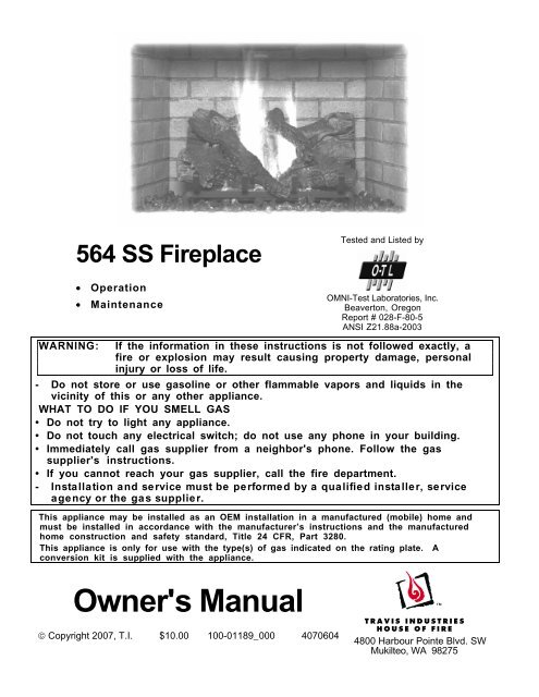
<strong>564</strong> <strong>SS</strong> Fireplace• Operation• MaintenanceTested and Listed byOMNI-Test Laboratories, Inc.Beaverton, OregonReport # 028-F-80-5ANSI Z21.88a-2003WARNING:If the information in these instructions is not followed exactly, afire or explosion may result causing property damage, personalinjury or loss of life.- Do not store or use <strong>gas</strong>oline or other flammable vapors and liquids in thevicinity of this or any other appliance.WHAT TO DO IF YOU SMELL GAS• Do not try to light any appliance.• Do not touch any electrical switch; do not use any phone in your building.• Immediately call <strong>gas</strong> supplier from a neighbor's phone. Follow the <strong>gas</strong>supplier's instructions.• If you cannot reach your <strong>gas</strong> supplier, call the fire department.- Installation and service must be performed by a qualified installer, serviceagency or the <strong>gas</strong> supplier.This appliance may be installed as an OEM installation in a manufactured (mobile) home andmust be installed in accordance with the manufacturer’s instructions and the manufacturedhome construction and safety standard, Title 24 CFR, Part 3280.This appliance is only for use with the type(s) of <strong>gas</strong> indicated on the rating plate. Aconversion kit is supplied with the appliance.Owner's Manual© Copyright 2007, T.I. $10.00 100-01189_000 40706044800 Harbour Pointe Blvd. SWMukilteo, WA 98275
2 IntroductionIntroductionWe welcome you as a new owner of a <strong>564</strong> <strong>SS</strong> <strong>gas</strong> <strong>fireplace</strong>. This manual details operation andmaintenance of this <strong>fireplace</strong>. Please familiarize yourself with the Owner's Manual before operating yourheater and save the manual for future reference.Important InformationNo other <strong>564</strong> <strong>SS</strong> <strong>gas</strong> <strong>fireplace</strong> has the same serialnumber as yours. The serial number is on the listinglabel that is chained to the <strong>gas</strong> control valve. This serialnumber may be needed in case you require service.Model: <strong>564</strong> <strong>SS</strong> FireplaceSerial Number:Purchase Date:Purchased From:Register your warranty online at:traviswarranty.comOr, mail your warranty card to:Travis Industries House of Fire4800 Harbour Pointe Blvd. SWMukilteo, WA 98275Save Your Bill of Sale.To receive full warranty coverage, you willneed to show evidence of the date youpurchased your heater. Do not mail your Billof Sale to us.Installation WarningsWe suggest that you attach your Bill of Saleto this page so that you will have all theinformation you need in one place shouldthe need for service or information occur.• Installation requirements are printed in the <strong>564</strong> <strong>SS</strong> Installation Manual (part# 100-01188). All requirements in the installation manual must be met.• Failure to follow all of the requirements may result in property damage,bodily injury, or even death.• This heater must be installed by a qualified installer who has gone througha training program for the installation of direct vent <strong>gas</strong> appliances.• This appliance must be installed in accordance with all local codes, if any;if not, follow ANSI Z223.1 and NFPA 54(88).• In Manufactured or Mobile Homes must conform with Manufactured HomeConstruction and Safety Standard, Title 24 CFR, Part 3280, or, when such astandard is not applicable, the Standard for Manufactured HomeInstallations, ANSI/NCSBCS A225.1. This appliance may be installed inManufactured Housing only after the home is site located.• The <strong>fireplace</strong> is designed to operate on natural <strong>gas</strong>, or propane (LP).• All exhaust <strong>gas</strong>es must be vented outside the structure of the living-area.Combustion air is drawn from outside the living-area structure.• Notify your insurance company before hooking up this <strong>fireplace</strong>.© Travis Industries 4070626 100-01189_000
Table of ContentsIntroduction 3Introduction and Important InformationIntroduction.............................................................2Important Information ................................................2Installation Warnings.................................................2Features .................................................................3Heating Specifications...............................................3Safety PrecautionsSafety Precautions ...................................................4OperationBefore You Begin......................................................6Location of Controls ..................................................6Starting The Pilot Flame..............................................6Starting the Fireplace for the First Time..........................8Turning the Fireplace On and Off..................................8Adjusting the Flame Height..........................................8Adjusting the Optional Blower Speed.............................9Normal Operating Sounds...........................................9Normal Operating Odors.............................................9MaintenanceMaintaining Your Fireplace's Appearance ...................... 10Yearly Service Procedure........................................... 10Grill Installation and Removal...................................... 11Face Installation and Removal..................................... 12Glass Frame Removal and Installation .......................... 13Log Set Installation................................................... 15Glass Cleaning......................................................... 22Troubleshooting Table ............................................... 23How this Fireplace Works ........................................... 24Wiring Diagram......................................................... 25Replacement Parts List.............................................. 25WarrantyWarranty................................................................. 26Optional EquipmentOptional Equipment List............................................. 27IndexIndex ..................................................................... 28Features• Works During Power Outages (millivolt system)• Optional Thermostat or Remote Control• Realistic "Wood Fire" Look• Optional Blower for Effective Heat Distribution• Convenient Operating Controls• Variable-Rate Heat Output• Low MaintenanceHeating SpecificationsNatural GasPropaneApproximate Heating Capacity (in square feet)* 950 950Maximum BTU Input Per Hour 20,500 20,500Minimum BTU Input on Low 5,100 4,200Steady State Efficiency** (with blowers on) 76.5 % 74.2 %* Heating capacity will vary with floor plan, insulation, and outside temperature.** Efficiency rating is a product thermal efficiency rating determined under continuous operationindependent of installed system.© Travis Industries 4070626 100-01189_000
4 Safety PrecautionsIF YOU SMELL GAS:* Do not light any appliance* Extinguish any open flame* Do not touch any electrical switch or plug or unplug anything* Open windows and vacate building* Call <strong>gas</strong> supplier from neighbor's house, if not reached, call firedepartmentThis unit must be installed by a qualified installer to prevent the possibility of an explosion.Your dealer will know the requirements in your area and can inform you of those peopleconsidered qualified. The room heater should be inspected and cleaned before use andat least annually by a qualified service person. More frequent cleaning may be requireddue to excessive lint from carpeting, bedding material, etc.The instructions in this manual must be strictly adhered to. Do not use makeshift methodsor compromise in the installation. Improper installation will void the warranty and safetylisting.OkLook for this label:For LPG only | Pout 11” W.C.If the label is present, theheater is equipped for LP(propane). If the label isabsent, the heater is equippedfor NG (natural <strong>gas</strong>).Contact your local buildingofficials to obtain a permit andinformation on any installationrestrictions or inspectionrequirements in your area.Notify your insurance companyof this heater as well.This heater is either approved for natural <strong>gas</strong>(NG) or for propane (LP). Burning the incorrectfuel will void the warranty and safety listing andmay cause an extreme safety hazard. Directquestions about the type of fuel used to yourdealer. Check the label and flame adjust knobon the <strong>gas</strong> control valve.If the flame becomes sooty, darkorange in color, or extremely tall,do not operate the heater. Callyour dealer and arrange forproper servicing.It is imperative that controlcompartments, screens, orcirculating air passageways ofthe heater be kept clean andfree of obstructions. Theseareas provide the air necessaryfor safe operation.?Donot operate the heater if it isnot operating properly in anyfashion or if you are uncertain.Call your dealer for a fullexplanation of your heater andwhat to expect.GasDo not store or use <strong>gas</strong>oline orother flammable liquids in thevicinity of this heater.Do not operate if any portion ofthe heater was submerged inwater or if any corrosion occurs.Immediately call a qualifiedservice technician to inspect theappliance and to replace any partof the control system and any <strong>gas</strong>control that has been underwater.© Travis Industries 4070626 100-01189_000
Safety Precautions 5Do not place clothing or otherflammable items on or near theheater. Because this heater canbe controlled by a thermostatthere is a possibility of the heaterturning on and igniting any itemsplaced on or near it.The viewing glass should beopened only for lighting thepilot or conducting service. Donot operate with cracked,broken, or removed glass.Any safety screen or guardremoved for servicing must bereplaced prior to operating theheater.Operate the heater according tothe instructions included in thismanual.If the main burners do not startcorrectly turn the <strong>gas</strong> off at the<strong>gas</strong> control valve and call yourdealer for service. Light the heater using the built-inpiezo igniter. Do not usematches or any other externaldevice to light your heater.Allow the heater to cool beforecarrying out any maintenance orcleaning.Never remove, replace, modify orsubstitute any part of the heaterunless instructions are given inthis manual. All other work mustbe done by a trained technician.Don't modify or replace orifices.The pilot flame must contact thethermopile and thermocouple(see the illustration to the left). Ifit does not, turn the <strong>gas</strong> controlvalve to "OFF" and call yourdealer.This unit is not for use with solidfuelDo not place anything inside thefirebox (except the includedfiber logs).If the fiber logs becomedamaged, replace with TravisIndustries log set.ThisManualDo not throw this manual away.This manual has importantoperating and maintenanceinstructions that you will need at alater time. Always follow theinstructions in this manual.Children and adults should bealerted to the hazards of highsurface temperature and shouldstay away to avoid burns orclothing ignition. Young childrenshould be supervised whenthey are in the same room as theheater.Travis Industries, Inc.grants no warranty, impliedor stated, for theinstallation or maintenanceof your heater, andassumes no responsibilityof any consequentialdamage(s).Instruct everyone in the househow to shut <strong>gas</strong> off to theappliance and at the <strong>gas</strong> mainshutoff valve. The <strong>gas</strong> mainshutoff valve is usually next tothe <strong>gas</strong> meter or propane tankand requires a wrench to shutoff.© Travis Industries 4070626 100-01189_000
6 OperationBefore You Begin• Read this entire manual before you use your new <strong>fireplace</strong> (especially the section "SafetyPrecautions" on pages 4 & 5). Failure to follow the instructions may result in property damage, bodilyinjury, or even death.Location of ControlsThe Pilot Flame can befound under the rear log .Pilot IgniterON/OFF SwitchOptional Blower ControlOptional Accent LightComfort ControlGas Control ValveLift the control cover up and swing itforward to access the controls.Flame Adjust KnobGas Control KnobAn instruction card for operatingthe <strong>fireplace</strong> is attached to theinside of the <strong>fireplace</strong> here.Replace it for easy reference.Pilot IgniterOn/Off SwitchGas Control KnobThe pilot igniter is used only to start the pilot. When pressed, it sends anelectrical charge to the pilot assembly. This creates a blue spark directly nextto the pilot, igniting the pilot flame.This control is used to turn the <strong>fireplace</strong> burners on and off.This knob is used to control <strong>gas</strong> to the <strong>fireplace</strong> and for starting the pilot.There are three positions, ON, OFF, & PILOT. The pointer to the left of theknob indicates the position this knob is in.Flame Adjust Knob This knob controls the flame height from low ("LO") to high ("HI"). The pointerabove the knob points to the position this knob is in.Comfort Control This lever turns the rear burner on and off.NOTE: THIS IS NOT A SHUTOFF VALVE.Optional Blower Control This knob controls the speed of the optional internal convection blowerthat pushes heated air into the room.Optional Accent Light This knob controls the optional accent lights located behindthe logs.© Travis Industries 4070626 100-01189_000
Starting The Pilot FlameThe pilot flame is required to ignite the mainburners (it also plays a safety role). It should beleft on once lit. It will stay lit unless the <strong>gas</strong>control valve is turned to "OFF". However, thepilot will go out if the <strong>gas</strong> is shut off, thepropane tank runs out (or low) or if the stovemalfunctions. If the pilot turns off frequently,call your dealer for information. To start thepilot follow the directions below:WARNING:When lighting or re-lighting the pilot,the glass must be removed (see page10).aRemove the glass (see page 10 for details).Operation 7ab5 minutesbPush the <strong>gas</strong> control knob in slightly and turnit to the "OFF" position. The knob will notturn from "ON" to "OFF" unless the knob isdepressed slightly. Wait five minutes to letany <strong>gas</strong> that may have accumulated insidethe firebox escape. If you smell leaking <strong>gas</strong>,follow the directions on the cover "IF YOUSMELL GAS".cPILOTIGNITERcTurn the <strong>gas</strong> control knob to the "PILOT"position and press the knob in, this will allow<strong>gas</strong> to flow to the pilot light. Press thebutton on the pilot igniter repeatedly untilyou see the pilot light.WARNING:If the pilot does not light after 15seconds, release the knob and call yourdealer for service. Do not attempt tolight pilot until service has beenperformed.NOTE:You may wish to remove the log set togain a better view of the pilot (see page15).d Keep the <strong>gas</strong> control knob depressed for 30seconds once it is lit.efgRelease the <strong>gas</strong> control knob. If the pilotgoes out, repeat step C. If the pilot refusesto stay lit, call your dealer for service. Withthe pilot lit, proceed to step “f”.Replace the glass.Turn the <strong>gas</strong> control knob counter-clockwiseto "ON". The pilot is now lit and the heatercan be turned on and off.defg30 seconds?© Travis Industries 4070626 100-01189_000
°FMIN8 OperationStarting the Fireplace for the First Time• Burn the heater at a high setting with the blower off for an extended period (up to 48 hours). This willcure the painted surfaces. Fumes from the paint curing and oil burning off the steel will occur. This isnormal. We recommend opening a window to vent the room.• Condensation may appear on the glass each time you start the <strong>fireplace</strong> - this is normal.• Blue Flames will occur on the <strong>fireplace</strong> when it first comes on. After fifteen minutes the flames willturn a more realistic yellow and orange color.• Certain installations use a remote "wall switch" to turn the <strong>fireplace</strong> on and off. If this is the case, leavethe ON/OFF switch "ON".Turning the Fireplace On and OffAfter the pilot has been started...°FSET TEMPTIMERROOM TEMPOFFTimeSetONTimeCancelOFFAut oA switch is provided behindthe control cover (belowthe firebox).A wall switch may beused to turn the<strong>fireplace</strong> on and off.An optional remote may beused (see the instructionsincluded with the remote).An optional wall thermostatmay be used to control thetemperature.NOTE FOR REMOTES, THERMOSTATS, OR WALL SWITCHES:The on/off switch on the <strong>fireplace</strong> may be required to be left in the ON or OFF position for the <strong>fireplace</strong> tooperate. Consult your installer or dealer for details.• Do not place any combustible items on top of or directly in front of the <strong>fireplace</strong>, even temporarily. Theoptional thermostat may start the <strong>fireplace</strong> causing a combustible item to ignite.• If the <strong>fireplace</strong> turns on and off frequently while using the thermostat, you may want to adjust the flameheight down until it produces just enough heat needed.Adjusting the Flame Height• Your <strong>fireplace</strong> has an adjustable flame to tailor the look and heat output to your specific needs. It isadjusted by turning the middle dial on the <strong>gas</strong> control valve.Flame HeightAdjustment KnobIndex MarkTurn counter-clockwise to adjust the flame higher, clockwise to lower.© Travis Industries 4070626 100-01189_000
Adjusting the Optional Blower SpeedOperation 9The blower helps transfer heat from the heater into the room. It will not turn on until the heater is up totemperature (approximately 10 minutes after starting). See the illustration below for instructions onadjusting the blower speed.NOTE:With the rear burner off (comfort control), the heater may not become hot enough for theblower to turn on.OFFTurn the dial all theway counter-clockwiseuntil it clicks off.HIGHThe high position is all theway counter-clockwise,without clicking off.LOWTurn the dial all theway clockwise.Normal Operating SoundsThe appliance may creak with change oftemperature -- THIS IS NORMAL.Blower Snap DiskThis part can produce aclicking sound as it turnsthe blower on and off.Gas Control ValveAs the <strong>gas</strong> control valve is turnedon and off you will hear a dullclicking sound. This is the valveNormal Operating OdorsBlowersThis heater has optional blowers to pushheated air into the room. You will hear thesound of air movement that increases asthe speed is increased.Extinction PopsIt is not unusual, especially on Propane(LP) appliances, to experience a "pop"when the burner is shut off.Pilot FlameThe pilot flame, which remains on,makes a very slight "whisper" sound.This appliance has several areas that reach high temperatures. Dust or other particles on these areas mayburn and create an odor. This is normal during start-up. You may notice the smell is more acute if theappliance was left idle for a long period.© Travis Industries 4070626 100-01189_000
10 MaintenanceMaintaining Your Fireplace's AppearanceFingerprints or other marks left on the optional plated surface may become etched in place if they are notwiped clean prior to turning the <strong>fireplace</strong> on. Clean the plated surface with denatured alcohol and a softcloth (with the <strong>fireplace</strong> cool). Other cleaners may leave a film that may become etched into the surface.Yearly Service Procedure• Failure to inspect and maintain the <strong>fireplace</strong> may lead to improper combustion and a potentially dangeroussituation. We recommend the following procedures be done by a qualified technician.1. Check the pilot flame. It should touch approximately 3/8" of the top of the thermopile and touch the top of thethermocouple (see illustration below). If it does not, contact your dealer for service.2. Shut off <strong>gas</strong> to the <strong>fireplace</strong> by turning the <strong>gas</strong> control knob to "OFF" (see step A under "Starting the Pilot" onpage 7). Let the <strong>fireplace</strong> cool for 15 minutes. Remove the glass (see page 10).3. Remove the log set (NOTE: the logs are very fragile - see page 15). If severely deteriorated, replace.Check the logs for sooting. A small amount of soot along the bottom of the logs is normal. If excessive sootingis found, the <strong>fireplace</strong> will require adjustment. Contact your dealer.4. Inspect the burner and remove any debris.• Make sure the burner is not warped, cracked, or damaged.• Check the firebox and area around the pilot to make sure there is no warping or damage.• If any problem is found, discontinue use and contact your dealer for service.Before Disassembly - Check the pilot flame. Itshould touch the thermocouple and thermopile.ThermopileCheck the walls and ceilingof the firebox fordeterioration.Pilot HoodCheck the burner holes.ThermocoupleMake sure the burners are notwarped or damaged.5. Replace the log set. Clean and replace the glass (see Glass Cleaning on page 22). If the glass is damaged,replace. Make sure the <strong>gas</strong>ket along the perimeter of the glass contacts the face of the firebox and forms an airtightseal. If it does not, re-align or replace the <strong>gas</strong>ket to insure an air-tight seal.6. Inspect the area behind the access door. Clean if necessary. Check the <strong>gas</strong> control valve and the <strong>gas</strong> lines. Ifdamage is found, discontinue use and contact your dealer for service. Clean the air channels, ducts, and blower(if applicable).7. Start the pilot and turn on the main burner. The flames should be orange/yellow and not touch the top of thefirebox. If the pilot or main burners do not burn correctly, contact your dealer for service. Monitor the bloweroperation.8. Remove any debris or vegetation near the vent termination. Contact your dealer if any sooting or deterioration isfound near the vent termination.© Travis Industries 4070626 100-01189_000
Grill Installation and RemovalFollow the directions below to install.Upper Grill Installation (FPX and Avalon)Maintenance 11Hold the grill at an angle and insert thelower slot over the lower bushing onthe <strong>fireplace</strong> (both sides)Swing the grill upwards to engage the upper slot. Youwill need to lift the grill slightly to get it over the bushing.Once in place the grill is held in place by gravity.Upper Grill Installation (<strong>Lopi</strong>)NOTE: The upper grill is difficult to install the first time - bepatient, after you install it, you will know how it installs and itwill be much easier the second time.SIDE VIEWHeat Shields(on <strong>fireplace</strong>)Mounting StudUpper GrillPosition the grillso the slots onthe grill align withthe mountingstuds.You may need topush in andupwards on thegrill as it inserts.The grill, whenfully inserted,will slide downand “click” intoplace.Lower Grill InstallationHold the grill at an angle and insert the lowerslot over the bushing on the <strong>fireplace</strong> (bothsides). You may need press on the grill to getthe tab over the bushing (this prevents thegrill from accidentally falling off).Bend the tab outward onboth sides. This is theend-stop for the lower grill,it allows the grill to swingforward.Swing the grill upwards to engagethe upper slot. You will need to liftthe grill slightly to get it over thebushing. Once in place the grill isheld in place by gravity.© Travis Industries 4070626 100-01189_000
12 MaintenanceFace Installation and RemovalSome <strong>fireplace</strong>s have a face that fits over the glass frame. The face can be removed following thedirections below.PhillipsScrewdriverFour screws hold the facein place. The screws areaccessed through thegrills on the face.© Travis Industries 4070626 100-01189_000
Glass Frame Removal and InstallationaMaintenance 13Warning: The appliance must be completely cool before removing the glass.Warning: Do not strike or slam the glass.Based upon the face being used, either:(a) swing the access door down and remove the top grill,(b) remove the face (unscrew or lift off - see theinstructions included with the face for details).Open the four latches holding the glass frame in place(start with the bottom three) - follow the directions shownto the right.LatchTop ofFireboxGlassbLift the glass frame up andpull it forward to remove.NOTE:You may need to liftthe glass framewhile re-attaching.Catch(on glass frame)Re-Attaching the Glass Frame:a) Hang the glass frame on the firebox.b) While holding in place, attach the upper latches(follow the instructions to the right in reverse).c) Lift the glass frame slightly and attach the lower latches.NOTE: Make sure the glass frame is all the way in place - itshould be flush with the front of the <strong>fireplace</strong> when installed.© Travis Industries 4070626 100-01189_000
14 MaintenanceGlass Frame Removal and Installation (continued)The latch can come loose from the latch assembly. This occurs only when it is rotated. Follow thedirections below to re-install the latch if it comes loose.Hold the latch at an angle and insert it into the slot on the glass frame anchor.LatchGlass FrameAnchorTop ofFireboxNOTE: this slot may be at adifferent angle than illustrated.Note how the washer on the latch fits behind the flange on theglass frame anchor.Once fully inserted, turn the latch until it is upright.© Travis Industries 4070626 100-01189_000
Maintenance 15Log Set InstallationLog Set OverviewWhen installed, the logs should appear as shown below.Rear LogRight TwigLeft Log Left Twig Right Log© Travis Industries 4070626 100-01189_000
16 MaintenanceRear Log InstallationThe rear log has a flat notchon both sides that center iton the grate.Place the rear log on the grateand slide it all the way back untilthe log contacts the endbracketson the grate.© Travis Industries 4070626 100-01189_000
Right Log InstallationMaintenance 17The left log has a groove thatfits over the grate.Note how the left side of the logrests on the burner but does notcover any burner holes.© Travis Industries 4070626 100-01189_000
18 MaintenanceLeft Log InstallationThe left log has a groovethat fits over the grate.Note how the right side of the logrests on the burner but does notcover any burner holes.© Travis Industries 4070626 100-01189_000
Left Twig InstallationMaintenance 19This hole fits over thepin on the rear log.The left twig should be positionedso the front edge contacts thegrate as shown above.© Travis Industries 4070626 100-01189_000
20 MaintenanceRight Twig InstallationThe right twig has twoholes for the pins on therear and right log.When in place the right twig willappear as shown above.© Travis Industries 4070626 100-01189_000
Ember InstallationMaintenance 21A bag of embers is provided to further enhance the firebox. Place the embers on the firebox floor and onthe burner. Do not place embers over any of the burner holes or air channels.© Travis Industries 4070626 100-01189_000
22 MaintenanceGlass CleaningThe glass may be cleaned with a nonabrasivecleaner. To clean the inside of theglass, simply remove the glass frame, place iton a non-scratching surface, and clean theinside surface.If the outside surface of the glass framerequires cleaning, follow the directionsbelow to remove the outer glass frame andscreen.WARNING: do not operate the <strong>fireplace</strong> without the glass frame and screen in place.Six sets of tabs hold the glass (and glass <strong>gas</strong>ket) in place. Four of these tabs are at the corners,two are at the top and bottom of the glass frame.GasketTabsInner FrameOuter FrameREMOVAL INSTRUCTIONS: carefully bend the tabs out with needle-nose pliers (there are tabson the inner and outer frame - the center tabs only have tabs on the inner frame). Do not prythese tabs, this may cause the glass to crack.REPLACEMENT INSTRUCTIONS: carefully bend the tabs inward, making sure the tabs contactthe <strong>gas</strong>ket, not the glass. Bend the tab inwards 30°- do not over-bend the tabs.With the outer glassframe and screenremoved, the outersurface of the glassmay be cleaned.Inner glass frameThe optional screen issandwiched betweenthe inner and outerglass frame.Outer glass frame© Travis Industries 4070626 100-01189_000
Troubleshooting TableMaintenance 23Problem: Possible Cause: Don't Call for ServiceUntil You:Pilot Will NotLightMain BurnersWill Not StartRemote ControlDoes Not WorkThermostat DoesNot WorkA <strong>gas</strong> shut off valve is turned offThe <strong>gas</strong> control knob isn't turned to "PILOT"The valve control knob isn't pushed inThe igniter wasn't pressed repeatedlyNo Propane in TankThe pilot light has gone outThe <strong>gas</strong> control valve is turned to "PILOT" or "OFF"The ON/OFF switch is turned to "OFF"The remote control is not working correctlyThe thermostat is disconnected or set too lowThe pilot light has gone outThe <strong>gas</strong> control valve is turned to "PILOT" or "OFF"The ON/OFF switch is turned to "OFF"The remote is too far away from the <strong>fireplace</strong>The remote control receiver is turned "Off"One of the two remote control batteries is deadThe pilot light has gone outThe <strong>gas</strong> control valve is turned to "PILOT" or "OFF"The ON/OFF switch is turned to "OFF"The thermostat is set too lowCheck all <strong>gas</strong> shut off valvesSee "Starting the Pilot Light" Step CSee "Starting the Pilot Light" Step CSee "Starting the Pilot Light" Step CCheck Tank LevelSee "Starting the Pilot Light"See "Starting the Pilot Light"Turn the ON/OFF switch to "ON"See the remote control instructionsSee "Thermostat Operation"See "Starting the Pilot Light"See "Starting the Pilot Light"Turn the ON/OFF switch to "ON"Use the remote closer to the <strong>fireplace</strong>See the remote control instructionsSee the remote control instructionsSee "Starting the Pilot Light"See "Starting the Pilot Light"Turn the ON/OFF switch to "ON"See "Thermostat Operation"Fireplace WillNot DistributeHeatPilot Goes OutIntermittentlyThe <strong>fireplace</strong> is not getting electricityThe <strong>fireplace</strong> is not up to temperatureThe <strong>gas</strong> supply has been shut offCheck the breaker switchSee "Operating Your Fireplace"Keep the <strong>gas</strong> supply turned onFlames Are TooBlueFlames Are TooShort (Under 6")Thin Layer ofSoot Covers theGlassThe <strong>fireplace</strong> has just been startedThis is normal - see "Starting the Fireplacefor the First Time"Improper air shutter adjustmentAdjust Air Shutter - contact your dealerThe flame height may be turned too low Turn the flame height to "HI" -See "Adjusting the Flame Height"The logs or coals are placed incorrectlyImproper air shutter adjustmentSee "Log Set Installation"Adjust Air Shutter - contact your dealer© Travis Industries 4070626 100-01189_000
24 MaintenanceHow this Fireplace WorksThis <strong>fireplace</strong> was designed with safety as the primary concern. Many of the components inside this<strong>fireplace</strong> are for safety purposes. Therefore, only certified <strong>gas</strong> service technicians should service this<strong>fireplace</strong>.What Turns the Main Burners On and OffThis <strong>fireplace</strong> uses a millivolt system to control its operation (a millivolt is a very small amount of electricity).The thermopile and thermocouple generate electricity when heated by the pilot flame. This electricity isused to operate the <strong>gas</strong> valve. Without enough electricity, the <strong>gas</strong> valve will not turn on. That is why whenstarting the pilot the <strong>gas</strong> control knob has to be pressed in long enough for the thermocouple to heat upand generate enough electricity. The thermopile provides power for the ON/OFF switch, remote control,or thermostat (see the illustration below). Because the thermopile generates the electricity needed toturn the <strong>fireplace</strong> on and off, this <strong>fireplace</strong> can be operated when the power is out (although the blower willnot run).When heated, the thermopilegenerates electricity (a very smallamount measured in "Millivolts").This electricity isused to operate themain burners.The main burnersare switched on andoff using theelectricity generatedby the thermopile.The ON/OFF switch,remote control, orthermostat controlthe circuit to the mainburner.MAIN BURNERONOFFWhat Prevents Gas BuildupThis appliance utilizes a high-technology <strong>gas</strong> valve in conjunction with a pilot flame to ensure no <strong>gas</strong> buildsup inside the firebox.The thermocouple (next to the pilot) senses when the pilot flame is lit. If the pilot flame goes out, thisthermocouple no longer generates electricity, causing the <strong>gas</strong> valve to automatically shut off all <strong>gas</strong> to theheater, preventing the pilot from spilling <strong>gas</strong> into the firebox.Pilot FlameThe pilot flame is a time-provencomponent that eliminates the possibilityof <strong>gas</strong> buildup inside the firebox.Gas ValveThis high-technology valve automaticallyshuts off all <strong>gas</strong> if it does not receive a signalfrom the thermocouple. If any component isdamaged or sensing a malfunction, or if thewiring is damaged, it will shut off all <strong>gas</strong>.ThermocoupleThe thermocouple generates a smallamount of electricity. If the pilot flamegoes out, the <strong>gas</strong> valve automaticallyshuts off all <strong>gas</strong>.External Shut Off ValveThis valve is placed on the <strong>gas</strong> lineto shut off <strong>gas</strong> to the applianceduring maintenance procedures.© Travis Industries 4070626 100-01189_000
26 Limited 7 Year WarrantyTo register your TRAVIS INDUSTRIES, INC. 7 Year Warranty, complete the enclosed Warranty card and mail it within ten (10) days of the appliancepurchase date to: TRAVIS INDUSTRIES, INC., 4800 Harbour Pointe Blvd. SW, Mukilteo, WA 98275. TRAVIS INDUSTRIES, INC. warrants this <strong>gas</strong>appliance (appliance is defined as the equipment manufactured by Travis Industries, Inc.) to be defect-free in material and workmanship to the originalpurchaser from the date of purchase as follows:Check with your dealer in advance for any costs to you when arranging a warranty call.Mileage or service charges are not covered by this warranty. This charge can vary from store to store.Years 1 & 2 - COVERAGE: PARTS & LABORBurner Assembly:Gas Control AssemblyBurner, Burner Pan, Air Shutter Assembly, Main BurnerOrificeFirebox Assembly:Adjustable Air Restrictor, Pressure Relief Mechanisms,Barometric Control Mechanism (for models with Remote HeatDucts), Glass Attachment MechanismElectrical Assembly (within heaterstructure):Adjustable control valve, millivolt wiring and connectors (located withinthe metal heater structure), thermopile, thermocouple, pilot hood,orifices, pilot <strong>gas</strong> line, piezo ignitorGlassGlass (breakage from thermal shock)Ceramic LogsLog Set, Coals, Ember Strip (Steel Fiber)Gold, Nickel & Copper PlatingBlower, wiring harness, snap discs, rheostat speed controlFace & Door (see “Conditions and Exclusions” # 9)Exclusions: Paint, GasketingYears 3 THROUGH 5 - COVERAGE: PARTS & LABORConvection Heat ExchangerFirebox Assembly:AccessoriesCast Brick, Cast Firebacks, Power Heat Ducts, AndironsConvection Heat ExchangerRe-Installation AllowanceIn cases where heater must be removed from home forrepairs, a partial cost of re-installation is covered (preauthorizationrequired)One-Way Freight AllowanceOne-way freight allowance on pre-authorized repair done atfactory is covered.One-Way Freight AllowanceAdjustable Air Restrictor, Pressure Relief Mechanisms,Barometric Control Mechanism (for models withRemote Heat Ducts), Glass Attachment MechanismOne-way freight allowance on pre-authorized repair done atfactory is covered.Exclusions: Paint, Gasketing, Burner Assembly, Electrical Assembly, Gas Control Assembly, Glass, Ceramic Logs, Gold, Nickel & CopperPlating, Accessories, Re-Installation AllowanceYears 6 & 7 - COVERAGE: PARTS ONLYFirebox Assembly:Adjustable Air Restrictor, Pressure Relief Mechanisms, Barometric Control Mechanism (for models with Remote Heat Ducts), Glass Attachment MechanismExclusions:Paint, Gasketing, Burner Assembly, Electrical Assembly, Gas Control Assembly, Glass, Ceramic Logs, Gold, Nickel & CopperPlating, Accessories, Convection Heat Exchanger, Re-Installation Allowance, One-Way Freight Allowance, LaborCONDITIONS & EXCLUSIONS1. This new <strong>gas</strong> appliance must be installed by a qualified <strong>gas</strong> appliance technician. It must be installed, operated, and maintained at all times in accordance with the instructions in the Owner’sManual. Any alteration, willful abuse, accident, neglect, or misuse of the product shall nullify this warranty.2. This warranty is nontransferable, and is made to the ORIGINAL purchaser, provided that the purchase was made through an authorized TRAVIS dealer.3. Discoloration and some minor expansion, contraction, or movement of certain parts and resulting noise, is normal and not a defect and, therefore, not covered under warranty. The installermust ensure the appliance is burning as per the rating tag at the time of installation. Over-firing (operation above the listed BTU rate) of this appliance can cause serious damage and will nullifythis warranty.4. The warranty, as outlined within this document, does not apply to the chimney components or other Non-Travis accessories used in conjunction with the installation of this product. If in doubt asto the extent of this warranty, contact your authorized TRAVIS retailer before installation.5. Travis Industries will not be responsible for inadequate performance caused by environmental conditions such as nearby trees, buildings, roof tops, wind, hills or mountains or negative pressureor other influences from mechanical systems such as furnaces, fans, clothes dryers, etc.6. This Warranty is void if:a. The unit has been operated in atmospheres contaminated by chlorine, fluorine or other damaging chemicals.b. The unit is subject to submersion in water or prolonged periods of dampness or condensation.c. Any damage to the unit, combustion chamber, heat exchanger or other components due to water, or weather damage which is the result of, but not limited to, improper chimney/ventinginstallation.7. Exclusions to this 7 Year Warranty include: injury, loss of use, damage, failure to function due to accident, negligence, misuse, improper installation, alteration or adjustment of themanufacturer's settings of components, lack of proper and regular maintenance, damage incurred while the appliance is in transit, alteration, or act of God.8. This 7 Year warranty excludes damage caused by normal wear and tear, such as paint discoloration or chipping, worn or torn <strong>gas</strong>keting, corroded or cracked logs, embers, etc. Also excluded isdamage to the unit caused by abuse, improper installation, modification of the unit, drilling of the orifices, or the use of fuel other than that for which the unit is configured. Units are shipped fornatural <strong>gas</strong> and must be converted to propane using the included conversion kit. Confirm fuel configuration with your installer.9. Damage to gold or nickel surfaces caused by fingerprints, scratches, melted items , or other external sources left on the gold or nickel from the use of cleaners other than denatured alcohol isnot covered in this warranty.10. TRAVIS INDUSTRIES, INC. is free of liability for any damages caused by the appliance, as well as inconvenience expenses and materials. Incidental or consequential damages are not coveredby this warranty. In some states, the exclusion of incidental or consequential damage may not apply.11. This warranty does not cover any loss or damage incurred by the use or removal of any component or apparatus to or from the <strong>gas</strong> appliance without the express written permission of TRAVISINDUSTRIES, INC. and bearing a TRAVIS INDUSTRIES, INC. label of approval.12. Any statement or representation of TRAVIS products and their performance contained in TRAVIS advertising, packaging literature, or printed material is not part of this 7 year warranty.13. This warranty is automatically voided if the appliance’s serial number has been removed or altered in any way. If the appliance is used for commercial purposes, it is excluded from this warranty.14. No dealer, distributor, or similar person has the authority to represent or warrant TRAVIS products beyond the terms contained within this warranty. TRAVIS INDUSTRIES, INC. assumes noliability for such warranties or representations.15. Travis Industries will not cover the cost of the removal or re-installation of hearths, facing, mantels, venting or other components.16. If for any reason any section of this warranty is declared invalid, the balance of the warranty remains in effect and all other clauses shall remain in effect.17. THIS 7 YEAR WARRANTY IS THE ONLY WARRANTY SUPPLIED BY TRAVIS INDUSTRIES, INC., THE MANUFACTURER OF THE APPLIANCE. ALL OTHER WARRANTIES,WHETHER EXPRE<strong>SS</strong> OR IMPLIED, ARE HEREBY EXPRE<strong>SS</strong>LY DISCLAIMED AND PURCHASER’S RECOURSE IS EXPRE<strong>SS</strong>LY LIMITED TO THE WARRANTIES SET FORTHHEREIN.IF WARRANTY SERVICE IS NEEDED:1. If you discover a problem that you believe is covered by this warranty, you MUST REPORT it to your TRAVIS dealer WITHIN 30 DAYS, giving them proof of purchase, the purchase date,and the model name and serial number.2. Travis Industries has the option of either repairing or replacing the defective component.3. If your dealer is unable to repair your appliance’s defect, he may process a warranty claim through TRAVIS INDUSTRIES, INC., including the name of the dealership where you purchased theappliance, a copy of your receipt showing the date of the appliance’s purchase, and the serial number on your appliance. At that time, you may be asked to ship your appliance, freight chargesprepaid, to TRAVIS INDUSTRIES, INC. TRAVIS INDUSTRIES, INC., at its option, will repair or replace, free of charge, your TRAVIS appliance if it is found to be defective in material orworkmanship within the time frame stated within this 7 year warranty. TRAVIS INDUSTRIES, INC. will return your appliance, freight charges (years 1 to 5) prepaid by TRAVIS INDUSTRIES,INC., to your regional distributor, or dealership.4. Check with your dealer in advance for any costs to you when arranging a warranty call. Mileage or service charges are not covered by this warranty. This charge can vary from store to store.© Travis Industries 4070626 100-01189_000
AUTOON /FFlameHeightTimeCancelPM°FSET TEMP°FSetFanSp edAccessoriesOptional Equipment 27The accessories listed below are available at your Travis dealer. To locate a dealer, visit:www.travisproducts.comBlowerThe optional blowers help transfer heat to yourhome.FirebacksThere are several styles of decorative ceramicfirebacks that fit inside the firebox and enhancethe area behind the flames. These firebackscan also be painted in several colors availablefrom your professional hearth dealer. Remote ControlThis accessory allows for remote control of your<strong>fireplace</strong>.ROOM TEMPMA NUA LON /O FF:O F© Travis Industries 4070626 100-01189_000
28 IndexIndexAccessories.......................................................27Adjusting the Flame Height....................................8Adjusting the Optional Blower Speed.......................9Before You Begin ................................................6Blower Operation (optional) ...................................9Cleaning............................................................10Controls - Location ..............................................6Face Installation and Removal ...............................12Features............................................................3Flame Height Adjustment ......................................8Glass Cleaning ...................................................22Glass Frame Removal and Installation.....................13Grill Installation and Removal.................................11Heating Specifications .........................................3How this Fireplace Works......................................24Important Information...........................................2Installation Warnings ...........................................2Introduction .......................................................2Location of Controls.............................................6Log Set Installation..............................................15Maintaining Your Fireplace's Appearance.................10Normal Operating Odors....................................... 9Normal Operating Sounds..................................... 9Odors............................................................... 9On/Off Operation................................................ 8Optional Equipment List....................................... 27Parts................................................................ 25Pilot - Starting.................................................... 6Replacement Parts List........................................ 25Safety Precautions............................................. 4Smells.............................................................. 9Starting the Fireplace for the First Time ................... 8Starting The Pilot Flame ....................................... 6Troubleshooting Table ......................................... 23Turning the Fireplace On and Off............................ 8Warranty........................................................... 26Window Cleaning ................................................ 22Window Removal and Installation........................... 13Wiring Diagram................................................... 25Yearly Service Procedure..................................... 10© Travis Industries 4070626 100-01189_000