864 ST Fireplace Installation Manual - Lopi
864 ST Fireplace Installation Manual - Lopi
864 ST Fireplace Installation Manual - Lopi

Create successful ePaper yourself
Turn your PDF publications into a flip-book with our unique Google optimized e-Paper software.
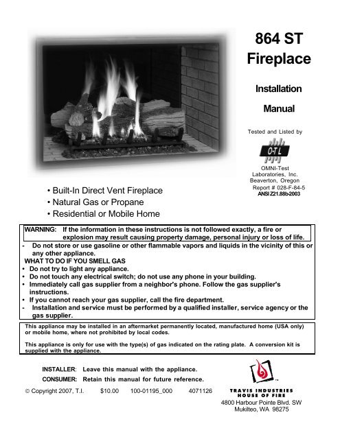
<strong>864</strong> <strong>ST</strong><strong>Fireplace</strong><strong>Installation</strong><strong>Manual</strong>Tested and Listed by• Built-In Direct Vent <strong>Fireplace</strong>• Natural Gas or Propane• Residential or Mobile HomeOMNI-TestLaboratories, Inc.Beaverton, OregonReport # 028-F-84-5ANSI Z21.88b-2003WARNING: If the information in these instructions is not followed exactly, a fire orexplosion may result causing property damage, personal injury or loss of life.- Do not store or use gasoline or other flammable vapors and liquids in the vicinity of this orany other appliance.WHAT TO DO IF YOU SMELL GAS• Do not try to light any appliance.• Do not touch any electrical switch; do not use any phone in your building.• Immediately call gas supplier from a neighbor's phone. Follow the gas supplier'sinstructions.• If you cannot reach your gas supplier, call the fire department.- <strong>Installation</strong> and service must be performed by a qualified installer, service agency or thegas supplier.This appliance may be installed in an aftermarket permanently located, manufactured home (USA only)or mobile home, where not prohibited by local codes.This appliance is only for use with the type(s) of gas indicated on the rating plate. A conversion kit issupplied with the appliance.IN<strong>ST</strong>ALLER: Leave this manual with the appliance.CONSUMER: Retain this manual for future reference.© Copyright 2007, T.I. $10.00 100-01195_000 40711264800 Harbour Pointe Blvd. SWMukilteo, WA 98275
2 IntroductionOverviewThis manual details the installationrequirements for the <strong>864</strong> <strong>ST</strong> (See Through)fireplace. For operating and maintenanceinstructions, refer to the <strong>864</strong> <strong>ST</strong> Owner's <strong>Manual</strong>(part # 100-01196).Listing DetailsThis appliance was listed by OMNI-TestLaboratories, Inc. to ANSI Z21.88 - report # 028-F-84-5. The listing label is attached to theappliance near the gas control valve. A copy isshown to the right.IAS (ICBO) ApprovalThis appliance was listed by OMNI-TestLaboratories, Inc. - IAS # TL130 (previouslyICBO).Massachusetts ApprovalThis manual has been submitted to theMassachusetts Board of State Examiners ofPlumbers and Gas FittersNational <strong>Fireplace</strong> Institute© Travis Industries 4071126 100-01195_000
Table of Contents 3IntroductionOverview.................................................................2Listing Details..........................................................2Safety PrecautionsSafety Precautions...................................................4Features and SpecificationsFeatures.................................................................6<strong>Installation</strong> Options...................................................6Heating Specifications ..............................................6Dimensions.............................................................6<strong>Installation</strong>Packing List.............................................................7Additional Items Required..........................................7Recommended <strong>Installation</strong> Procedure .........................7Massachusetts Requirements.....................................8Top Vent or Side Vent Configuration............................9Converting the <strong>Fireplace</strong> to Side Vent Configuration...9<strong>Fireplace</strong> Placement Requirements.............................11Clearances...........................................................11Raised <strong>Fireplace</strong>s .................................................11Min. Framing Dims................................................12Nailing Brackets....................................................13Gas Line Requirements.............................................14Fuel ....................................................................14Gas Line Connection .............................................14Gas Inlet Pressure ................................................14Gas Line Location .................................................15Electrical Connection (required)..................................16Wall Switch or Thermostat <strong>Installation</strong> .........................17Wiring Diagram (Millivolt System) ............................17Wall Switch <strong>Installation</strong>...........................................17Vent Requirements...................................................18Vent Clearances ...................................................18Altitude Considerations ..........................................18Approved Vent......................................................19Vent <strong>Installation</strong>....................................................19Approved Vent Configurations....................................20Restrictor Position.................................................20Exhaust Restrictor Adjustment................................20Intake Restrictor Adjustment...................................21Diffuser Plate Adjustment.......................................22Side Vent Config. W Horizontal Term. (no vertical rise).. 23Side Vent Config. W Horizontal Term. (w vertical rise)....24Side Vent Configuration with Vertical Termination ..........25Top Vent Configuration with Horizontal Termination........26Top Vent Configuration with Vertical Termination ...........27Termination Requirements.........................................28<strong>Installation</strong> (continued)Hearth Requirements ............................................... 29Facing Requirements ............................................... 30Drywall <strong>Installation</strong> ................................................30Facing Overview ...................................................31Optional Faceplates – Sizing Chart..........................31Thin Facing <strong>Installation</strong>..........................................32Thick Facing <strong>Installation</strong>.........................................34Thick Facing <strong>Installation</strong> with FPX Arched Faces........35Mantel Requirements................................................ 37Install Example - Build-Out (Dog-House) w Hor. Term.... 37Finalizing the <strong>Installation</strong>Steps for Finalizing the <strong>Installation</strong> ............................. 38Starting the Pilot Flame .........................................38Pilot Flame Inspection...........................................38Air Shutter Adjustment...........................................39Glass Frame Removal and <strong>Installation</strong>........................ 40Log Set <strong>Installation</strong> .................................................. 42Optional EquipmentLP Conversion Instructions ....................................... 52Fireback <strong>Installation</strong> ................................................. 56Grill <strong>Installation</strong>........................................................ 58Remote Control Receiver <strong>Installation</strong> (2 Options) ......... 59Extra Room Power Heat Duct (sku 98500769)............ 60Andiron <strong>Installation</strong>................................................... 61IndexIndex...................................................................... 62© Travis Industries 4071126 100-01195_000
4 Safety PrecautionsSafety Warnings:• Failure to follow all of the requirements may result in property damage, bodily injury, or even death.• This unit must be installed by a qualified installer to prevent the possibility of an explosion.• This appliance must be installed in accordance with all local codes, if any; if not, in U.S.A. follow ANSIZ223.1 and NFPA 54(88).• In Manufactured or Mobile Homes must confirm with: In USA, Manufactured Home Construction andSafety Standard, Title 24 CFR, Part 3280, or, when such a standard is not applicable, the Standard forManufactured Home <strong>Installation</strong>s, ANSI/NCSBCS A225.1. This appliance may be installed inManufactured Housing only after the home is site located.• All exhaust gases must be vented outside the structure of the living-area. Combustion air is drawnfrom outside the living-area structure.• Notify your insurance company before hooking up this fireplace.• The room heater should be inspected before use and at least annually by a qualified service person.More frequent cleaning may be required due to excessive lint from carpeting, bedding material, etc.• The instructions in this manual must be strictly adhered to. Do not use makeshift methods orcompromise in the installation. Improper installation will void the warranty and safety listing.• This heater is approved for use with natural gas (NG) or propane (LP). Burning the incorrect fuel willvoid the warranty and safety listing and may cause an extreme safety hazard. Direct questions aboutthe type of fuel used to your dealer. Check the label and flame adjust knob on the gas control valve.• Contact your local building officials to obtain a permit and information on any installation restrictions orinspection requirements in your area.• If the flame becomes sooty, dark orange in color, or extremely tall, do not operate the heater. Call yourdealer and arrange for proper servicing.• It is imperative that control compartments, screens, or circulating air passageways of the heater bekept clean and free of obstructions. These areas provide the air necessary for safe operation.• Do not operate the heater if it is not operating properly in any fashion or if you are uncertain. Call yourdealer for a full explanation of your heater and what to expect.• Do not store or use gasoline or other flammable liquids in the vicinity of this heater.• Do not operate if any portion of the heater was submerged in water or if any corrosion occurs.• Do not place clothing or other flammable items on or near the heater. Because this heater can becontrolled by a thermostat there is a possibility of the heater turning on and igniting any items placedon or near it.• Light the heater using the built-in piezo igniter. Do not use matches or any other external device tolight your heater.• Never remove, replace, modify or substitute any part of the heater unless instructions are given in thismanual. All other work must be done by a trained technician. Don't modify or replace orifices.• The viewing glass should be opened only for lighting the pilot or conducting service.• Any safety screen or guard removed for servicing must be replaced prior to operating the heater.Travis Industries 4071126 100-01195_000
Safety Warnings (continued):Safety Precautions 5• Allow the heater to cool before carrying out any maintenance or cleaning.• Operate the heater according to the instructions included in this manual.• If the main burners do not start correctly turn the gas off at the gas control valve and call your dealer forservice.• The pilot flame must contact the thermopile and thermocouple. If it does not, turn the gas controlvalve to "OFF" and call your dealer.• This unit is not for use with solid fuel.• Do not place anything inside the firebox (except the included logs).• If the fiber logs become damaged, replace with Travis Industries log set.• Do not throw this manual away. This manual has important operating and maintenance instructionsthat you will need at a later time. Always follow the instructions in this manual.• Do not touch the hot surfaces of the heater. Educate all children of the danger of a high-temperatureheater. Young children should be supervised when they are in the same room as the heater.• Due to the high temperature, the heater should be located out of traffic and away from furniture anddraperies.• Instruct everyone in the house how to shut gas off to the appliance and at the gas main shutoff valve.The gas main shutoff valve is usually next to the gas meter or propane tank and requires a wrench toshut off.• Travis Industries, Inc. grants no warranty, implied or stated, for the installation ormaintenance of your heater, and assumes no responsibility of any consequentialdamage(s).© Travis Industries 4071126 100-01195_000
6 Features and Specifications<strong>Installation</strong> Options• Residential or Mobile Home• Internal or External Chase• Flush or Recessed Face• Horizontal or Vertical Vent• Raised or Floor Placement• Bedroom ApprovedHeating SpecificationsNatural GasPropaneApproximate Heating Capacity (in square feet)* Up to 1,500 Up to 1,500Maximum BTU Input Per Hour 37,500 37,500* Heating capacity will vary with floor plan, insulation, and outside temperature.Dimensions41-1/2"3-3/8"Side Vent Configuration8" Diameter Vent38-1/4"Top Vent Configuration39-1/8"8" Diameter Vent4-3/8"35-1/4"38-1/4"37"1"33-7/8"Lifting Handle TabsThese tabs may beused in conjuction withthe lifting handles(98500711) - make sureto use the required24"41"42-1/2"BackLeftRightFrontadapters (250-01038)Weight: 310 Lbs.Travis Industries 4071126 100-01195_000
Packing ListFinalizing the <strong>Installation</strong> (for qualified installers only) 7• Propane Conversion Kit• Log SetAdditional Items Required• Direct Vent• Gas Line Equipment (shutoff valve, pipe, etc.)• Electrical Equipment (min. 14 gauge, grounded line)• Two Grill Kits and/or FacesRecommended <strong>Installation</strong> Procedure• Wall Switch with Wire (see page 17 for details)• Firestop (sku 93006094)• Prepare the framing, making sure to leave the area around the fireplace open (see page12). Make sure to allow for vent installation and facing depth.• Place the fireplace into position.• Install the vent, gas line and electrical hook-up.• Finalize the framing around the fireplace.• Secure the fireplace to the framing.• Install the wall switch (see page 17) or thermostat (if applicable).• Install the drywall.• Install the hearth (if applicable).• Install the facing (if applicable).• Install the mantel (if applicable).• Finalize the installation (see page 38) and install the grill or face.© Travis Industries 4071126 100-01195_000
8 Finalizing the <strong>Installation</strong> (for qualified installers only)Massachusetts RequirementsNOTE: The following requirements reference various Massachusetts and national codes not contained in this document.Requirements for the Commonwealth of MassachusettsFor all side wall horizontally vented gas fueled equipment installed in every dwelling, building or structure used in whole or inpart for residential purposes, including those owned or operated by the Commonwealth and where the side wall exhaust venttermination is less than seven (7) feet above finished grade in the area of the venting, including but not limited to decks andporches, the following requirements shall be satisfied:<strong>Installation</strong> of Carbon Monoxide DetectorsAt the time of installation of the side wall horizontal vented gas fueled equipment, the installing plumber or gasfitter shallobserve that a hard wired carbon monoxide detector with an alarm and battery back-up is installed on the floor level where thegas equipment is to be installed. In addition, the installing plumber or gasfitter shall observe that a battery operated or hardwired carbon monoxide detector with an alarm is installed on each additional level of the dwelling, building or structure servedby the side wall horizontal vented gas fueled equipment. It shall be the responsibility of the property owner to secure theservices of qualified licensed professionals for the installation of hard wired carbon monoxide detectors.In the event that the side wall horizontally vented gas fueled equipment is installed in a crawl space or an attic, the hard wiredcarbon monoxide detector with alarm and battery back-up may be installed on the next adjacent floor level.In the event that the requirements of this subdivision can not be met at the time of completion of installation, the owner shallhave a period of thirty (30) days to comply with the above requirements; provided, however, that during said thirty (30) dayperiod, a battery operated carbon monoxide detector with an alarm shall be installed.Approved Carbon Monoxide DetectorsEach carbon monoxide detector as required in accordance with the above provisions shall comply with NFPA 720 and beANSI/UL 2034 listed and IAS certified.SignageA metal or plastic identification plate shall be permanently mounted to the exterior of the building at a minimum height of eight(8) feet above grade directly in line with the exhaust vent terminal for the horizontally vented gas fueled heating appliance orequipment. The sign shall read, in print size no less than one-half (1/2) inch in size, “GAS VENT DIRECTLY BELOW. KEEPCLEAR OF ALL OB<strong>ST</strong>RUCTIONS”.InspectionThe state or local gas inspector of the side wall horizontally vented gas fueled equipment shall not approve the installationunless, upon inspection, the inspector observes carbon monoxide detectors and signage installed in accordance with theprovisions of 248 CMR 5.08(2)(a)1 through 4.ExemptionsThe following equipment is exempt from 248 CMR 5.08(2)(a)1 through 4:• The equipment listed in Chapter 10 entitled “Equipment Not Required To Be Vented” in the most current edition of NFPA 54 asadopted by the Board; and• Product Approved side wall horizontally vented gas fueled equipment installed in a room or structure separate from thedwelling, building or structure used in whole or in part for residential purposes.MANUFACTURER REQUIREMENTSGas Equipment Venting System ProvidedWhen the manufacturer of Product Approved side wall horizontally vented gas equipment provides a venting system design orventing system components with the equipment, the instructions provided by the manufacturer for installation of theequipment and the venting system shall include:• Detailed instructions for the installation of the venting system design or the venting system components; and• A complete parts list for the venting system design or venting system.Gas Equipment Venting System NOT ProvidedWhen the manufacturer of a Product Approved side wall horizontally vented gas fueled equipment does not provide the partsfor venting the flue gases, but identifies “special venting systems”, the following requirements shall be satisfied by themanufacturer:• The referenced “special venting system” instructions shall be included with the appliance or equipment installationinstructions; and• The “special venting systems” shall be Product Approved by the Board, and the instructions for that system shall include aparts list and detailed installation instructions.A copy of all installation instructions for all Product Approved side wall horizontally vented gas fueled equipment, all ventinginstructions, all parts lists for venting instructions, and/or all venting design instructions shall remain with the appliance orequipment at the completion of the installation.See Gas Connection section for additional Commonwealth of Massachusetts requirements.Travis Industries 4071126 100-01195_000
Finalizing the <strong>Installation</strong> (for qualified installers only) 9Top Vent or Side Vent ConfigurationThis appliance is shipped in the top vent configuration. To change to the side vent configuration,follow the directions below.NOTE: the vent configuration affects several aspects of installation (framing, maximum vent rise,maximum vent run). When reviewing the installation requirements make sure to pay attention to thetype of configuration being used.Converting the<strong>Fireplace</strong> toSide VentConfigurationRemove the back plate onthe fireplace.NOTE: Use a magnetic-tippednutdriver on these screws -take care to prevent thescrews from falling into thefireplace.Remove the flue assembly.Tuck the two 24" pieces of insulationinto the area between the exhaustmanifold and fireplace can.WARNING: Failure to properlyplace the insulation will void thewarranty and create a safetyhazard.© Travis Industries 4071126 100-01195_000
10 Finalizing the <strong>Installation</strong> (for qualified installers only)Convertingthe <strong>Fireplace</strong>to Side Vent(continued)Re-attach the flue assemblyin the side position.Tuck the two 20" pieces of insulationinto the area above the exhaustmanifold and fireplace can. Note howthe insulation is folded in half andcovers the entire area above theexhaust manifold (see illustrationbelow).WARNING: Failure to properlyplace the insulation will void thewarranty and create a safetyhazard.Re-attach the back plate to thetop of the fireplace.NOTE: Make sure the flange onthe back plate tucks between thefireplace and the flue assembly.Travis Industries 4071126 100-01195_000
Finalizing the <strong>Installation</strong> (for qualified installers only) 11<strong>Fireplace</strong> Placement Requirements• <strong>Fireplace</strong> must be installed on a level surface capable of supporting the fireplace and vent• <strong>Fireplace</strong> must be placed directly on wood or non-combustible surface (not on linoleum or carpet)• This heater may be placed in a bedroom. Please be aware of the large amount of heat thisappliance produces when determining a location.• <strong>Fireplace</strong> must be installed in a room with a minimum ceiling height of 84”.Clearances• The fireplace requires a 1/2" clearance from the left side of the fireplace to the framingmembers. No material (insulation, framing, etc.) may be placed into this area.1/2" Clearnceon left side offireplace.0" clearance onright side offireplace.• When installed, walls either in front or behind the fireplace must be a minimum 1" to the side ofthe fireplace. Only 1 side wall is allowed within 12” of the side of the fireplace.• Due to the high temperature, the heater should be located out of traffic and away from furnitureand draperies.• <strong>Fireplace</strong> must be placed so the vents below and above the glass do not become blocked.Raised <strong>Fireplace</strong>s• The fireplace (and hearth, if desired) may be placed on a platform designed to support thefireplace (310 Lbs.) and vent.PlatformMin. 42”<strong>Fireplace</strong>EnclosureHeightOptional Raised Hearth(see “Hearth Requirements” for details)© Travis Industries 4071126 100-01195_000
12 Finalizing the <strong>Installation</strong> (for qualified installers only)Minimum Framing Dimensions – Top or Side Vent ConfigurationMinimum 42” <strong>Fireplace</strong>Enclosure HeightNOTE:Due to the flue assembly on thefireplace, we recommend you installthe framing after placing thefireplace in position.As an alternative, you may omit theframing above the front of the fireplaceuntil the fireplace is in position (shownin dark gray). In addition, if using theside vent configuration, do not installthe framing to the left side (shown inlight gray). 38-1/2"42-1/2"23" *LeftFrontBackRight* The 23" dimension is based upon 1/2" drywall around theperimeter of the fireplace on both sides. If using thicker drywall(or other facing), you will need to adjust this dimension.Travis Industries 4071126 100-01195_000
Finalizing the <strong>Installation</strong> (for qualified installers only) 13Nailing BracketsThere are eight nailing brackets on the front andback of the fireplace. Follow the directions belowto prepare thenailing brackets. Once inplace, nail or screw thenailing brackets to theframing.NOTE: Additional nailing brackets areprovided along the base of thefireplace. Use these brackets if notusing the front brackets.NOTE: You may need to bend thetabs out on one side then slide thefireplace out to bend the tabs out onthe opposite sideWARNING: Make sure thefireplace is square and plumbwhen placed in the framing.Measured corner-to-corner, thefireplace should be square(approx. 54-7/8” for eachdimension). Use shims toinsure the fireplace is square.1/2” DrywallTOP VIEWFramingFor installations using 1/2” facingfold the larger tabs out 90° onthe right side (use a screwdriverif necessary). Bend the tabs outon the left side<strong>Fireplace</strong>DrywallNailing Bracket5/8” DrywallFor installations using 5/8” drywall fold the shorter tabout 90° on the right side. (use a screwdriver ifnecessary). On the left side, remove the side standoff(screws hold it in place) and re-attach it in thealternative holes provided.TOP VIEW<strong>Fireplace</strong>FramingNailing BracketDrywall© Travis Industries 4071126 100-01195_000
14 Finalizing the <strong>Installation</strong> (for qualified installers only)Gas Line RequirementsFuelMASSACHUSETTS IN<strong>ST</strong>ALLATIONS - WARNING:THIS PRODUCT MU<strong>ST</strong> BE IN<strong>ST</strong>ALLED BY A LICENSED PLUMBER OR GAS FITTER WHEN IN<strong>ST</strong>ALLED WITHINTHE COMMONWEALTH OF MASSACHUSETTS.OTHER MASSACHUSETTS CODE REQUIREMENTS:• Flexible connector must not be longer than 36 inches.• Shutoff valve must be a “T” handle gas cock.• Only direct vent sealed combustion products are approved for bedrooms or bathrooms.• <strong>Fireplace</strong> dampers must be removed or welded in the open position prior to the installation of a fireplace insert or gaslog.• A carbon monoxide (CO) detector is required in the same room as the appliance.• The gas line must be installed in accordance with all local codes, if any; if not, follow ANSI223.1 and the requirements listed below.• The fireplace and gas control valve must be disconnected from the gas supply piping duringany pressure testing of that system at test pressures in excess of 1/2 psig. For pressures under 1/2psig, isolate the gas supply piping by closing the manual shutoff valve.• Leak test all gas line joints and the gas control valve prior to and after starting the fireplace.• This fireplace is designed either for natural gas or for propane (but not for both). Check the sticker on the top ofthe gas control valve to make sure the correct fuel is used.Gas Line Connection• <strong>Installation</strong> must be performed by a qualified installer, service agency or the gas supplier (In Massachusettsa licensed plumber/gasfitter).Standard Input Pressure Minimum Input Pressure Maximum Input PressureGas Inlet PressureNatural Gas 7" W.C. (1.74 kPA) 3.5" W.C. (0.87 kPA) 13.85" W.C. (3.45 kPA)Propane 13" W.C. (2.73 kPA) 8" W.C. (1.99 kPA) 14" W.C. (3.48 kPA)• If the pressure is not sufficient, make sure the piping used is large enough, the supply regulator isadequately adjusted, and the total gas load for the residence does not exceed the amount supplied.• The supply regulator (the regulator that attaches directly to the residence inlet or to the propane tank) shouldsupply gas at the suggested input pressure listed above. Contact the local gas supplier if the regulator is atan improper pressure.Travis Industries 4071126 100-01195_000
Finalizing the <strong>Installation</strong> (for qualified installers only) 15Gas Line LocationRight Side Gas Inlet (preferred)A 8" flex tube and shutoff valve isincluded with the fireplace. Theshutoff valve accepts a 1/2"MPT.A 2" by 3" opening is located behind the gasinlet cover plate (it is centered 3" above thebase of the fireplace).6-1/4"10-1/2"The gas inlet is located 3" abovethe base of the fireplace.You may remove this cover plate to install the gas line. Thecover plate has a 7/8" diameter hole (covered with a pushplug) in line with the gas inlet on the gas control valve. Byrotating the plate 180° the hole may be re-located. You mayalso secure the plate in a customized location using the selfdrillingscrews.Left Side Gas InletAn additional 2" by 3" opening is located theleft side (it is centered 3" above the base ofthe fireplace).A 8" flex tube and shutoff valve isincluded with the fireplace (you maywish to use a 24" or 36" flex tube).The shutoff valve accepts a 1/2" MPT.5-3/8"You may remove this cover plate to install thegas line. The cover plate has a 7/8" diameterhole (covered with a push plug) in line with thegas inlet on the gas control valve. By rotating theplate 180° the hole may be re-located. You mayalso secure the plate in a customized locationusing the self-drilling screws.© Travis Industries 4071126 100-01195_000
16 Finalizing the <strong>Installation</strong> (for qualified installers only)Electrical Connection (required)• The electrical line to the grounded receptacle inside the fireplace must be installed by aqualified installer and must meet all local codes.• Make sure the household breaker is shut off prior to working on any electrical lines.• The fireplace must be properly grounded in accordance with local codes (or ANSI/NFPA 70-1987)• The electrical line must be a min. 14 gauge, and supply 120 Volts at 60 Hz (2 Amps)Caution:Label all wires prior to disconnection when servicing controls. Wiring errors can causeimproper and dangerous operation.Grounded ReceptacleLeft Side of <strong>Fireplace</strong>Junction Box AssemblyReceptacle Cover PlateGrounded 110VPower SupplyStrain ReliefTravis Industries 4071126 100-01195_000
Finalizing the <strong>Installation</strong> (for qualified installers only) 17Wall Switch or Thermostat <strong>Installation</strong>Wiring Diagram (Millivolt System)Do not connect 110-120 VAC to the gas control valve or wiring system of this fireplace. The switch mustbe installed by a qualified installer.The included wall switch may be installed following the directions below. An optional thermostatmay also be installed. It is attached to the gas control valve in the same manner.Caution:Label all wires prior to disconnection when servicing controls. Wiring errors can causeimproper and dangerous operation.ThermocoupleThermopilePiezo IgniterOn/Off Switch (on fireplace)RedBrownCopper Co-AxialWireOrangeRedWhiteSpark ElectrodePilot HoodOptional Wall Switch,Thermostat, orRemote ControlWall Switch <strong>Installation</strong>1. Attach the included wire to the gas control valve.Attach the two wires to the top andbottom posts on the gas controlvalve (orientation does not matter).2. Determine a location for the wall switch (the wire is a maximum 25' long). Route the wire throughthe grommet near the gas inlet hole (either side) to the junction box and attach following thedirections below. Set the on/off switch on the appliance to "OFF" to control the appliance withthe wall switch.aInsert the wirethrough the back ofthe mountedjunction box (yourjunction box maylook different).Expose 1/2" ofeach wire. Securethe wires to theposts on the side ofthe on/off switch(orientation doesnot matter).StandardScrewdriverFromAppliancebCarefully pack the wires into thejunction box. Attach the switchto the junction box. Attach theswitchplate to the switch.StandardScrewdriver© Travis Industries 4071126 100-01195_000
18 Finalizing the <strong>Installation</strong> (for qualified installers only)Vent Requirements• The gas appliance and vent system must be vented directly to the outside of the building, andnever be attached to a chimney serving a separate solid fuel or gas-burning appliance. Eachdirect vent gas appliance must use it's own separate vent system.• In addition to the requirements listed here, follow the requirements provided with the vent.• A firestop is required whenever the vent penetrates a wall, floor, or ceiling (passes throughframing members). Horizontal vent less than 48" above the fireplace must use the TravisFirestop (sku 93006094 - it incorporates a 3" clearance above, 1" clearance below and to thesides of the vent). Other penetrations only require a 1" clearance and may use a standardfirestop (make sure the required 1" clearance is met).• Always use the high-wind termination (if available from the vent manufacturer).Vent Clearances• The vent must maintain the required clearance to combustible materials to prevent a fire. Donot fill air spaces with insulation.Before 48" Rise After 48" RiseSides 1" 1"Above 3" 1"Below Horizontal or 45° Section 1" 1"Vertical TerminationRequired FirestopHorizontalTerminationUse a roof flashing and storm collarwhenever passing through the roofUse a firestop wheneverpassing through a ceilingUse a support boxon exposed ventMin. 1"Min. 1"Min. 3"(1" if a minimum 48"above the fireplace)Min. 1"Altitude Considerations• This heater has been tested at altitudes ranging from sea level to 6,000 feet. In this testing we have foundthat the heater, with its standard orifice, burns correctly with just an air shutter adjustment.• Failure to adjust the air shutter properly may lead to improper combustion which can create a safety hazard.Consult your dealer or installer if you suspect an improperly adjusted air shutter.Travis Industries 4071126 100-01195_000
Approved VentFinalizing the <strong>Installation</strong> (for qualified installers only) 19• Side vent configurations use 8" diameter Simpson Dura-Vent Model Pro or GS vent.• Top vent configurations use 8" or 6-5/8" diameter Simpson Dura-Vent Model Pro or GS vent. Ifusing 6-5/8" diameter vent, attach the 8" to 6-5/8" reducer (Travis part # 98900165) to thefireplace.6-5/8" Diameter VentReducer - # 98900165Vent <strong>Installation</strong>• Slide the vent sections together and turn 1/4 turn until the sections lockin place.• Screws are not required to secure the vent. However, three screws maybe used to secure vent sections together if desired.• High temperature sealant is recommended at the appliance startersection connection (use high-temperature silicone or Mill-Pac®).• If disassembly is required, at time of re-assembly check to see if the ventcreates a tight fit. If it does not, apply high temperature sealant to thejoints of the affected sections.• Horizontal sections require a 1/4" rise every 12" of travel.• Horizontal sections require non-combustible support every three feet (e.g.: plumbing tape).© Travis Industries 4071126 100-01195_000
20 Finalizing the <strong>Installation</strong> (for qualified installers only)Approved Vent ConfigurationsRestrictor Position• Intake and exhaust restrictors are built into the appliance to adjust the flow rate of intake air andexhaust gases. Depending upon the vent configuration, you may be required to adjust therestrictor positions. The charts for acceptable vent configurations detail the correct ventrestrictor positions.Exhaust Restrictor AdjustmentIf the diffuser is required to be in position # 2, you may wish to adjust the diffuser while the exhaustrestrictor is removed (see page 22).Firebox RoofLeft Wall of Firebox(closed) #6# 5# 4# 3# 2(open - stock position) # 1Loosen these two screwson the exhaust restrictor.Slide the restrictor to the correctrestrictor position (see the illustrationbelow). The screw location indicatesrestrictor position. In this example, therestrictor is set in position # 3. Tightenthe screws to secure the restrictor.Left (vent) Side of FireboxTravis Industries 4071126 100-01195_000
Finalizing the <strong>Installation</strong> (for qualified installers only) 21Intake Restrictor AdjustmentThe intake restrictor is shipped in position # 1 (open). To adjust the restrictor to postion # 2 (closed,follow the instructions below.Restrictor PlateRemove this screw.Rotate the restrictor plate sothe left side hole lines up withthe screw-hole. Re-attach thescrew to lock the restrictor platein position # 2.© Travis Industries 4071126 100-01195_000
22 Finalizing the <strong>Installation</strong> (for qualified installers only)Diffuser Plate AdjustmentCertain vent configurations require the diffuser plate to be adjusted (refer to the approved ventconfiguration charts for details). Position # 2 is stock (flat). Position # 1 is bent. See the directionsbelow to change the diffuser to position #1.Firebox RoofBack Wall of FireboxRemove the exhaustrestrictor.1/4" Nutdriver1/4" NutdriverRemove the diffuser.DIFFUSER SIDE VIEWBefore (Stock - Position # 2)After (Position # 1)Bend the round portion of thediffuser 90° (position # 1).Secure the diffuser platewith the screwsremoved earlier.Replace the exhaustrestrictor (see “ExhaustRestrictor Adjustment”for restrictor settings).Travis Industries 4071126 100-01195_000
Finalizing the <strong>Installation</strong> (for qualified installers only) 23Side Vent Configuration with Horizontal Termination (no vertical rise)• The termination must fall within the shaded area shown in the chart. Use the indicated restrictorand diffuser positions.HINT:Travis Industries provides a minimum vent kit (sku 98900168). It includes a 4” section and ahoriztontal termination cap.See the charts below todetermine maximum ventOptional 45° ElbowTerminationVent with No 45° Elbow3 feet0 feet• Exhaust Restrictor # 1 (stock)• Intake Restrictor # 1 (stock)• Diffuser Position # 10 feet4' (max)• Min. 4" Horizontal Section• Max.48" Horizontal Section(s)Vent with 1 45° Elbow3 feet• Exhaust Restrictor # 1 (stock)• Intake Restrictor # 1 (stock)• Diffuser Position # 10 feet0 feet2' (max)• Min. 4" Horizontal Section• Max. 24" Horizontal Section(s)© Travis Industries 4071126 100-01195_000
24 Finalizing the <strong>Installation</strong> (for qualified installers only)Side Vent Configuration with Horizontal Termination (with vertical rise)• The termination must fall within the shaded area shown in the chart. Use the indicated restrictorand diffuser positions.• Up to four elbows (45° or 90°) may be used.• Only one horizontal elbow may be used.0 feet5 feet10 feet15 feet20' (max)22' (max)5 feetExhaust Restrictor # 4Intake Restrictor # 2Diffuser Position # 2 (stock)Exhaust Restrictor # 4Intake Restrictor # 1Diffuser Position # 1Exhaust Restrictor # 2 (stock)Intake Restrictor # 1 (stock)Diffuser Position # 120 feet 20 feet15 feet10 feet22' (max)15 feet10 feet5 feet0 feet0 feet0 feet5 feet10 feet15 feet20' (max)H2This is considered a horizontalelbow (it does not matterwhether it turns right or left).It may be a 90° or 45° elbow.Horizontal length is calculated by addingboth lengths of horizontal run(Horizontal Length = H1 + H2).H1This is considered avertical elbowTravis Industries 4071126 100-01195_000
Finalizing the <strong>Installation</strong> (for qualified installers only) 25Side Vent Configuration with Vertical Termination• The termination must fallwithin the shaded areashown in the chart. Use theindicated restrictor anddiffuser positions.• Up to four elbows (45° or90°) may be used.• Only one horizontal elbowmay be used.40' (max)35 feet30 feet25 feet0 feet5 feetExhaust Restrictor # 4Intake Restrictor # 2Diffuser Position # 1Exhaust Restrictor # 2Intake Restrictor # 1Diffuser Position # 120 feet 20 feet15 feet10 feet10 feet15 feet20' (max)40' (max)35 feet30 feet25 feet15 feet10 feet5 feet5 feet0 feet0 feet0 feet5 feet10 feet15 feet20' (max)H2This is considered a horizontalelbow (it does not matterwhether it turns right or left).It may be a 90° or 45° elbow.Horizontal length is calculated by addingboth lengths of horizontal run(Horizontal Length = H1 + H2).H1This is considered avertical elbow© Travis Industries 4071126 100-01195_000
26 Finalizing the <strong>Installation</strong> (for qualified installers only)Top Vent Configuration with Horizontal Termination• The termination must fall within the shaded area shown in the chart. Use the indicated restrictorand diffuser positions.• Up to four elbows (45° or 90°) may be used.• May use 8" or 6-5/8" diameter vent (see page for 18 details).• Only one horizontal elbow may be used.0 feet5 feet10 feet15 feet20' (max)21' (max)5 feetExhaust Restrictor # 4Intake Restrictor # 2Diffuser Position # 2 (stock)Exhaust Restrictor # 4Intake Restrictor # 1 (stock)Diffuser Position # 2 (stock)Exhaust Restrictor # 2Intake Restrictor # 1 (stock)Diffuser Position # 2 (stock)20 feet 20 feet15 feet10 feet21' (max)15 feet10 feet5 feet0 feet0 feet0 feet5 feet10 feet15 feet20' (max)H2This is considered a horizontalelbow (it does not matterwhether it turns right or left).It may be a 90° or 45° elbow.Horizontal length is calculated by addingboth lengths of horizontal run(Horizontal Length = H1 + H2).H1This is considered avertical elbowTravis Industries 4071126 100-01195_000
Finalizing the <strong>Installation</strong> (for qualified installers only) 27Top Vent Configuration with Vertical Termination• The termination must fallwithin the shaded areashown in the chart. Use theindicated restrictor anddiffuser positions.• Up to four elbows (45° or90°) may be used.• Only one horizontal elbowmay be used.• May use 8" or 6-5/8"diameter vent (see page for18 details).40' (max)35 feet30 feet25 feet0 feet5 feetExhaust Restrictor # 4Intake Restrictor # 2Diffuser Position # 2 (stock)Exhaust Restrictor # 3Intake Restrictor # 2Diffuser Position # 2 (stock)20 feet 20 feet15 feet10 feet10 feet15 feet20' (max)40' (max)35 feet30 feet25 feet15 feet10 feet5 feet5 feet0 feet0 feet0 feet5 feet10 feet15 feet20' (max)H2This is considered a horizontalelbow (it does not matterwhether it turns right or left).It may be a 90° or 45° elbow.Horizontal length is calculated by addingboth lengths of horizontal run(Horizontal Length = H1 + H2).H1This is considered avertical elbow© Travis Industries 4071126 100-01195_000
28 Finalizing the <strong>Installation</strong> (for qualified installers only)Termination Requirements! Venting terminals shall not be recessed into a wall or siding.ABCDEFGHIJKLMNMinimum 9" clearance from any door or windowMinimum 12" above any grade, veranda, porch, deck or balconyMinimum 3-3/8" from outside corner wallsNOTE: Clearance in accordance with local installation codes and the requirementsof the gas supplier.Minimum 12" from inside corner wallsNOTE: Clearance in accordance with local installation codes and the requirementsof the gas supplier.RoofSurface11” Min.6” Min.RoofEavesMinimum 11" clearance below unventilated soffits or roof surfacesMinimum 18" clearance below ventilated soffitsMinimum 6" clearance below roof eavesNOTE: Vinyl surfaces require 24"NOTE: Clearance in accordance with local installation codes and the requirements of the gas supplier.Minimum 12" clearance below a veranda, porch, deck or balconyNOTE: Permitted only if veranda, porch, deck, or balcony is fully open on a minumum of two sides beneath the floor.NOTE: Clearance in accordance with local installation codes and the requirements of the gas supplier.Minimum 48" clearance from any adjacent buildingMinimum 84" clearance above any grade when adjacent to public walkways or drivewaysNOTE: may not be used over a walkway or driveway shared by an adjacent buildingMinimum 9" clearance to any nonmechanical air supply inlet to the building or the combustion air inlet to any otherappliance.Minimum 36" clearance above any mechanical air supply inlet if within 10’ horizontallyMinimum 36" from the area above the meter/regulator (vent outlet)NOTE: Clearance in accordance with local installation codes and the requirements of the gas supplier.Minimum 36" from the meter/regulator (vent outlet)NOTE: Clearance in accordance with local installation codes and the requirements of the gas supplier.Minimum 12” above the roof line (for vertical terminations)Minimum 24” horizontal clearance to any surface (such as an exterior wall) – for vertical terminationsENMEKEAJGFDALCIHBNOTE: Measure clearances to the nearest edge of the exhaust hood.• Use the vinyl siding standoff when installing on an exterior with vinyl siding.• Vent termination must not be located where it will become plugged by snow or other materialTravis Industries 4071126 100-01195_000
Finalizing the <strong>Installation</strong> (for qualified installers only) 29Hearth RequirementsFloor Mounted for the access door).<strong>Fireplace</strong>sWARNING:Do not build a hearth morethan 1” above the baseplate(this area must remain clearIf installed near carpet or othercombustible flooring, the fireplacemust be raised so the base of theunit is above the carpet surface orflooring material.A non-combustible hearth is not required. However, ifthe heater is installed next to the floor, we recommenda hearth to protect the flooring surface fromdiscoloration or other negative impact from the heater.Raised <strong>Fireplace</strong>ssurface.<strong>Fireplace</strong> StandA hearth is not requiredwhen the fireplace israised above the flooring© Travis Industries 4071126 100-01195_000
30 Finalizing the <strong>Installation</strong> (for qualified installers only)Facing Requirements• This appliance is designed to allow for drywall (or other combustible facing) to contact thesides and top of the front and back of the fireplace.• Non-combustible facing (tile, masonry, etc.) must be placed over the fiber board on the frontand back of the fireplace (see "Facing Overview" on page 31 for further details).Drywall <strong>Installation</strong>Drywall <strong>Installation</strong> Drywall may beinstalled up to the front edge of the fireplace.If the fireplace is raised, drywall up to thebottom edge as well.The non-combustible fiberboard must remain in placeabove the fireplace. Noncombustiblefacing (tile,masonry, etc.) must beplaced over the fiber board.Do not install drywall (or anyother combustible) in frontof the fireplace.DrywallTOP VIEWFraming<strong>Fireplace</strong>Nailing BracketDrywallTravis Industries 4071126 100-01195_000
Facing OverviewFinalizing the <strong>Installation</strong> (for qualified installers only) 31Upgrade faces are available for this fireplace and may influence facing installation. Consult with yourTravis Dealer if you are using an upgrade face.Optional non-combustible facing may be installed on the fireplace. Use the guidelines below todetermine the location (also see the following pages for detailed diagrams.Tile Line Any non-combustible facing under 1" thick (see "Thin Facing" on page 32).Masonry Line Any non-combustible over 1" thick (see "Thick Facing" on page 34).Hearth LineNon-combustible hearth/facing should be installed up to this location (1" above the baseof the fireplace). The fireplace may be raised to accommodate thicker hearth materials.Masonry LineTile LineTile LineMasonry LineMasonry LineTile LineSPECIAL IN<strong>ST</strong>RUCTIONS FORWILMINGTON FACESRemove the center deflector (use needlenosepliers if necessary).Masonry LineTile LineHearth LineThese tabs bend downto allow for removal.Hearth LineTile LineMasonry LineTile LineMasonry LineNOTE: The hearth or facing can extend nogreater than 1” above the base of the fireplace.The fireplace may be raised to accommodatethicker hearth materials.Re-attach the deflector to the louver.Bend the tabs as shown, making surethe deflector is secure and flat.WARNING: The deflector must bereplaced in its original position if adifferent face or grill is used.Optional Faceplates – Sizing ChartName Height Width NotesFPX Artisan, Classic, Fr Ctry 35-3/4” 41” 45-3/4” Radius – May fit over top of tile facingWinthrop Victorian Lace 34-1/8” 36-7/8” Optional facing will butte to edge of faceplate (tile line)Wilmington Hearthview 35-3/4” 41” • Requires removal of center deflector (see above).• Face may fit over top of tile facingWinthrop Bungalow 34” 36-7/8” Optional facing will butte to edge of faceplate (tile line)© Travis Industries 4071126 100-01195_000
32 Finalizing the <strong>Installation</strong> (for qualified installers only)Thin Facing <strong>Installation</strong> (tile, marble, or other non-combustible under 1" thick)Upgrade faces are available for this fireplace and may influence facing installation. Consult with yourTravis Dealer if you are using an upgrade face.Do not install tile (or other material)in front of the glass frame,convection channel, or access panelopenings. This area must remainopen to access internal componentsand for convection air.TOP VIEW<strong>Fireplace</strong>FramingTile Facing is installed to thisedge of the fireplace.NOTE FOR FPX FACES:FPX arched faces require the FPX FaceUpgrade Kit (sku 98500686) and atriangular piece of facing in these uppercorners. See the instructions includedwith the face for further details.2-7/8”Nailing BracketDrywall7-7/8”Raised <strong>Fireplace</strong>s:Facing is installed 1” (maximum)above the base of the fireplace.Travis Industries 4071126 100-01195_000DrywallTile LineTile LineFRONT VIEW 37”2”Tile LineHearth LineFloor-Mounted <strong>Fireplace</strong>s or Raised Hearths:Build the hearth 1” (max.) above the base of thefireplace. The fireplace may be raised toaccommodate thicker hearth materials.Fiber Board (must remain in place)1-1/2”1-1/8”34-1/4”1”
Finalizing the <strong>Installation</strong> (for qualified installers only) 33Thin Facing <strong>Installation</strong> (tile, marble, under 1" thick) - Side ViewRaised <strong>Fireplace</strong>(with no Hearth)SIDE OFFloor-Mounted <strong>Fireplace</strong>(with Hearth)FIREPLACESIDE OFFIREPLACEDrywallTile(or other facing under 1” thick)FaceNote how the facing extends 1”above the base of the fireplace.1”<strong>Fireplace</strong> SupportFloorFloorDrywallTile(or other facing under 1” thick)FaceHearth (note how it extends under the face -max. 1” thick). The fireplace may be raisedto accommodate thicker hearth materials.Max. 1”© Travis Industries 4071126 100-01195_000
34 Finalizing the <strong>Installation</strong> (for qualified installers only)Thick Facing <strong>Installation</strong> (stone, brick, or other non-combustible over 1" thick)If using a <strong>Fireplace</strong> Xtrordinair (FPX) arched face, see "Thick Facing with a <strong>Fireplace</strong> Xtrordinair ArchedFaces" on page 35.Masonry LineMasonry LineDo not install masonry (or othermaterial) in front of thefireplace. This area must remainopen to install the face.TOP VIEW - Protruding MasonryFramingNailing Bracket<strong>Fireplace</strong>DrywallFloor-Mounted <strong>Fireplace</strong>s or Raised Hearths:Build the hearth 1” (max.) above the base of thefireplace. The fireplace may be raised toaccommodate thicker hearth materials.Raised <strong>Fireplace</strong>s:Masonry is installed 1” (maximum)above the base of the fireplace.DrywallMasonry LineHearth Line<strong>Fireplace</strong>MasonryTOP VIEW - Recessed MasonryFramingDrywall(or cement board, etc.)MasonryNOTE: The nailing brackets are not used for this typeof installation - secure the fireplace to the floor withthe brackets along the base of the fireplace.FRONT VIEWFiber Board (must remain in place) 1-1/2” 35-3/4” 1”41”Travis Industries 4071126 100-01195_000
Finalizing the <strong>Installation</strong> (for qualified installers only) 35Thick Facing with <strong>Fireplace</strong> Xtrordinair (FPX) Arched FacesThe following illustration shows facing considerations for those fireplaces utilizing FPX arched faces.The facing must be non-combustible and over 1" in depth.The <strong>Fireplace</strong> Xtrordinair <strong>864</strong>Masonry Template isrecommended for masonryinstallation (sku 98500688). Thetemplate helps locate andsupport the masonry as it beinginstalled.Before installing masonry, installthe FPX Face Upgrade Kit(98500686). This covers theupper corners.Masonry LineFloor-Mounted <strong>Fireplace</strong>s or Raised Hearths:Build the hearth 1” (max.) above the base of thefireplace. The fireplace may be raised toaccommodate thicker hearth materials.Raised <strong>Fireplace</strong>s:Masonry is installed 1” (maximum)above the base of the fireplace.DrywallHearth LineTOP VIEW<strong>Fireplace</strong>FaceFramingDrywallMasonryNailing BracketFiber Board (must remain in place)FRONT VIEW 1-1/2” 5”35-3/4”45-1/2” Radius1”41”© Travis Industries 4071126 100-01195_000
36 Finalizing the <strong>Installation</strong> (for qualified installers only)Thick Facing <strong>Installation</strong> - Side ViewFloor-Mounted <strong>Fireplace</strong>(with Hearth)Raised <strong>Fireplace</strong>(with no Hearth)SIDE OFFIREPLACESIDE OFFIREPLACE Face DrywallMasonry(or other non-combustibleover 1” thick)Hearth (note how it extends under the face -max. 1” thick). The fireplace may be raised toaccommodate thicker hearth materials.Max. 1”FloorDrywallMasonry(or other non-combustibleover 1” thick)Face (Behind Masonry)The masonry extends 1” abovethe base of the fireplace.1”<strong>Fireplace</strong> SupportFloorTravis Industries 4071126 100-01195_000
Finalizing the <strong>Installation</strong> (for qualified installers only) 37Mantel Requirements• The illustration below details mantel clearances and maximum mantel depth.• Any material that protrudes more than 3/4” from the non-combustible facing is considered a manteland must meet the mantel requirements.Mantel(combustible or non-combustible)MantelHeightAboveFace (a)18+”17”16”15”14”13”12”11”10”9”8”7”6”5”4”3”2”1”0”Maximum Mantel Depth (b)0” 1” 2” 3” 4” 5” 6” 7” 8” 9” 10”11” 12”a36-3/4”bCombustible mantel columns (legs) thatprotrude more than 3/4” from the glassframe must meet the sidewall clearance. Ifthey protrude 3/4” or less, they must meetthe facing clearance 2-1/4” from the glassframe).Base of the <strong>Fireplace</strong>Non-combustible mantel columns do nothave a minimum clearance.Examples:• If you wish to have a 8” deep mantel, it must be at least 6-3/4” above the fireplace face (43-1/2” above the base).• If you wish to have a mantel 8” above the fireplace face, it must be no deeper than 9”.© Travis Industries 4071126 100-01195_000
38 Finalizing the <strong>Installation</strong> (for qualified installers only)Steps for Finalizing the <strong>Installation</strong>1. Remove the glass (see page 40).NOTE: If using propane (LP) convert the appliance prior to installing the logs.2. We recommend you purge the gas line at this time (with the glass removed). This allows gas tobe detected once it enters the firebox, ensuring gas does not build up.3. Install the logs (see page 42).4. Turn on the gas to the fireplace. Turn on gas to the heater. Leak test all gas joints prior tostarting the appliance. Start the pilot.Starting the Pilot FlameWARNING: When lighting or re-lighting the pilot, the glass must be removed (see page 38).abcRemove the glass.Push the gas control knob in slightly and turn it to the "OFF" position. The knob will not turnfrom "ON" to "OFF" unless the knob is depressed slightly. Wait five minutes to let any gas thatmay have accumulated inside the firebox escape. If you smell leaking gas, follow thedirections on the cover "IF YOU SMELL GAS".Turn the gas control knob to the "PILOT" position and press the knob in, this will allow gas toflow to the pilot light. Press the button on the pilot igniter repeatedly until you see the pilotlight.WARNING:NOTE:If the pilot does not light after 15 seconds, release the knob and call your dealerfor service. Do not attempt to light pilot until service has been performed.You may wish to remove the log set to gain a better view of the pilot (see page 42).d Keep the gas control knob depressed for 30 seconds once it is lit.e Release the gas control knob. If the pilot goes out, repeat step C. If the pilot refuses to stay lit,call your dealer for service. With the pilot lit, proceed to step “f”.f Replace the glass.g Turn the gas control knob counter-clockwise to "ON". The pilot is now lit and the heater can beturned on and off.5. Check the pilot flame following the directions below.Pilot Flame InspectionThe pilot flame should look like the illustration below. Adjust the pilot flame if necessary.To adjust the pilot flame, turn this screw. Clockwiselowers the flame while counter-clockwise raises it.StandardScrewdriverThe pilot flame must contact the thermocouple andthermopile (see the illustration below). Adjust the pilot up ordown as necessary.6. Replace the glass.7. Start the main burner (the main burner circuit is detailed on page 17). Leak test all gas jointsagain.Travis Industries 4071126 100-01195_000
Finalizing the <strong>Installation</strong> (for qualified installers only) 398. Check the air shutter following the directions below.Air Shutter AdjustmentLet the heater burn for fifteen minutes (make sure the logs and glass are in place). The flames shouldbe yellow with no sooting. Adjust the air shutter, if necessary, to achieve the correct looking flame.CorrectNot Enough AirToo Much AirFlames should be blue at thebase, yellow-orange on the top.Air Shutter AdjustmentIf the flames are over 14" tall or sooty onthe ends, open the air shutter.If the flames are all blue andshort, close the air shutter.The air shutters may be adjusted while the burner is on (take care to prevent contacting the burnerarea).Center Burner Air Shutter ControlLeft = Less AirRight = More AirOuter Burner Air Shutter ControlLeft = Less AirRight = More Air9. Turn the flame adjust knob to its highest position - the flames should not contact the top of thefirebox. Check the flame on low position. The flames should burn off of each burner hole. Ifthe heater does not work correctly, contact your Travis dealer for a remedy.10. Give this manual to the home owner for future reference and fully explain operation of thisheater. For comprehensive operating and maintenance instructions, refer to the Owner's<strong>Manual</strong> (part # 100-01196).ACID WASH WARNING: Before installing the faceplate, make sure any masonry that has beentreated with acid wash has been properly neutralized (this is used primarily with brick faces). Acidwash (muriatic acid) is used to remove excess mortar. If not properly neutralized with an ammoniasolution, the plated face may develop a permanent tarnish when the acid evaporates over time.Contact your dealer if uncertain your facing has been properly neutralized.© Travis Industries 4071126 100-01195_000
40 Finalizing the <strong>Installation</strong> (for qualified installers only)Glass Frame Removal and <strong>Installation</strong>aWarning: The appliance must be completely cool before removing the glass.Warning: Do not strike or slam the glass.Based upon the face being used, either:(a) swing the access door down and remove the top grill,(b) remove the face (unscrew or lift off - see theinstructions included with the face for details).Open the four latches holding the glass frame in place(start with the bottom three) - follow the directions shownto the right.LatchTop ofFireboxGlassbLift the glass frame up andpull it forward to remove.NOTE:You may need to liftthe glass framewhile re-attaching.Catch(on glass frame)Re-Attaching the Glass Frame:a) Hang the glass frame on the firebox.b) While holding in place, attach the upper latches(follow the instructions to the right in reverse).c) Lift the glass frame slightly and attach the lower latches.NOTE: Make sure the glass frame is all the way in place - itshould be flush with the front of the fireplace when installed.Travis Industries 4071126 100-01195_000
Finalizing the <strong>Installation</strong> (for qualified installers only) 41Glass Frame Removal and <strong>Installation</strong> (continued)The latch can come loose from glass frame anchor. This occurs when it is turned 1/4 turn when it isdisengaged. Follow the directions below to re-install the latch if it becomes loose.Hold the latch at an angle and insert it into the slot on the glass frame anchor.LatchNOTE: this slot may be at adifferent angle than illustrated.Top ofFireboxGlass FrameAnchorNote how the washer on the latch fits behind the flange on theglass frame anchor.Once fully inserted, turn the latch until it is upright.© Travis Industries 4071126 100-01195_000
42 Finalizing the <strong>Installation</strong> (for qualified installers only)Log Set <strong>Installation</strong>Logs in Place – FRONT SIDE (gas control valve side)NOTE: This fireplace has a front side and back side. The front side (pictured belowj) is the sidewith the gas control valve.Logs in Place – BACK SIDETravis Industries 4071126 100-01195_000
Finalizing the <strong>Installation</strong> (for qualified installers only) 43Center Log <strong>Installation</strong>Bend these two tabs up 90°. They are usedas pins to locate the center log.The log shelf has two tabsused to align the center log.Bend these tabs as shown tothe right.Place the center log inplace. Make sure the twotabs on the log shelf insertinto the two holes on thebottom of the log.Once in place,rotate the logclockwise untilthe indents inthe log contactthe grate.© Travis Industries 4071126 100-01195_000
44 Finalizing the <strong>Installation</strong> (for qualified installers only)Front Left LogPlace the front left log as shown below. There is a ledge on the bottom of the log that aligns withthe edge of the center burner.When in place, the front left log has a small gap to the center log.Travis Industries 4071126 100-01195_000
Finalizing the <strong>Installation</strong> (for qualified installers only) 45Front Left Upper LogThere are two pins on the frontleft log. The pin to the right isused to locate the front leftupper log.The front left upper log has a groove andone hole on the bottom. The groove fitsover the edge of the burner.When in place, the front left upper loglooks like the picture to the right.© Travis Industries 4071126 100-01195_000
46 Finalizing the <strong>Installation</strong> (for qualified installers only)Front Upper Center LogThe front upper center loghas two holes on its bottomsurface. One of the holes fitsover the pin on the centerlog (see picture to the right).The other fits over the pin onthe front left log.When in place,the front uppercenter log lookslike the pictureto the right.Travis Industries 4071126 100-01195_000
Back Left LogFinalizing the <strong>Installation</strong> (for qualified installers only) 47The back left log fits to the left of thecenter log.The groove on the bottom of the log fitsover the upper burner tray.Make sure to slide the log towards thecenter of the firebox. When in place, thelog will appear as shown in the picture tothe right.© Travis Industries 4071126 100-01195_000
48 Finalizing the <strong>Installation</strong> (for qualified installers only)Right Ember ChunkThe right ember chunk is installed fromthe back. The groove on the bottom ofthe ember fits over the edge of the upperburner tray. It wedges between the twologs..When in place, the left ember chunklooks like the picture to the right.Back Ember ChunkThe back ember in placed onthe back right side as shown inthe picture to the right. Makesure it is not over any burnerholes.Travis Industries 4071126 100-01195_000
Back Left LogFinalizing the <strong>Installation</strong> (for qualified installers only) 49The pin on the center log inserts into thehole on the back of the back left log.This groove on the log fits over the grate.When in place, the log looks like thepicture to the right.© Travis Industries 4071126 100-01195_000
50 Finalizing the <strong>Installation</strong> (for qualified installers only)Back Upper Right LogPins on the center log and back right loghelp locate this log.When in place, the back upper right loglooks like the picture to the right.Travis Industries 4071126 100-01195_000
Finalizing the <strong>Installation</strong> (for qualified installers only) 51Ember PlacementA bag of embers is provided to further enhance the firebox. Place the embers on the firebox floorand on the outer burner (especially over exposed rivets on the burner). Do not place embers overany of the burner holes or air channels. See the picture below.© Travis Industries 4071126 100-01195_000
52 Optional Equipment (for qualified installers only)LP Conversion InstructionsInstall the conversion kitprior to installing the gasline to ensure proper gasuse.1/4" Nutdriver1 Remove the glass (seepage 40). Remove thelogs and coals (ifinstalled - page 42).Remove the grate andfirebacks (see page 52).2 Remove the centerburner (see illustrationto the right).Remove the grate from both sides.NOTE: lift the burner to remove the grate.Remove the log shelfFour screws hold the centerburner in place. Slide theburner to the right and up toremove.Travis Industries 4071126 100-01195_000
Optional Equipment (for qualified installers only) 533 Follow the directions below to remove the outer burner and replace the orifices.aRemove theouter burner.Center Burner OrificeOuter Burner OrificeMake sure this gasket isreplaced when re-installing.bRemove this mixing tube cover.cUse a 1/2” open end wrench to unscrew the two orifices.Manifold1/2" WrenchCenter Burner OrificedApply thread sealant tothe LP orifices prior toinstallation. Use thechart below to identifythe correct orifices.Outer Burner OrificeeScrew each LP orificein so the orificeprotrudes 15/16”(indicating fullinsertion).15/16”Look here for the orificeidentificationNG LPCenter #48 #55Outer #44 #55© Travis Industries 4071126 100-01195_000
54 Optional Equipment (for qualified installers only)4 Remove the pilot orifice following the instructions below. Replace with the propane pilotorificeaLift the pilot hoodoff the pilotcRemove the orifice and replace with the LP orifice. Screw theorifice all the way in and replace the pilot hood.assembly.Orifice Identification:LP (Propane) OrificebUse a hex wrench tounscrew the orifice.3535NG (Natural Gas) Orifice625/32" HexNOTE: when re-attaching,this pin lines up with thenotch in the pilot hood.5 Replace the firebox components. Install the logs and embers. Replace the glass.Travis Industries 4071126 100-01195_000
Optional Equipment (for qualified installers only) 556 Remove theregulator from thefront of the gascontrol valve.Replace with thepropane regulator,using the newgasket and screwsincluded with theregulator. NOTE:Leak test thisarea after theheater isinstalled, gas isconnected, andthe main burner islit.7 Make the gas lineconnection, bleedthe gas line (ifapplicable), startthe heater andthoroughly leaktestall gasconnections andthe gas controlvalve. Check thepilot (see theillustration below.Adjust ifnecessary.WARNING:When lighting or relightingthe pilot, theglass must be removed(see page 40).aRemove and discard the threescrews using a slotted screwdriverof Torx T-20.SlottedScrewdriver(or T-20 Torx)cInstall the LP regulator. Usethe screws included with theLP regulator. Tighten toapproximately 25 Lbs. torque.SlottedScrewdriver(or T-20 Torx)bRemove and discard theregulator, diaphram, springand center post.NOTE: Make sure theregulator gasket is correctlyaligned before installation.dPlace the LPlabel on the baseof the fireplacenear the gascontrol valve.To adjust the pilot flame, turn this screw (NOTE: if totallyunscrewed gas will come out of this port). Clockwiselowers the flame while counter-clockwise raises it.StandardScrewdriverThe pilot flame must contact the thermocouple andthermopile (see the illustration below). Adjust the pilot up ordown as necessary.© Travis Industries 4071126 100-01195_000
56 Optional Equipment (for qualified installers only)Fireback <strong>Installation</strong>WARNINGTurn off gas to the appliance and make sure it has fully cooled prior to conductingservice.1 Remove the glass frame and logs (see the installation manual for details).2 Remove the front and rear grates (see the illustration below).1/4" NutdriverRemove the grate from both sides.NOTE: lift the burner to remove the grate.3 Remove and discard the steel ember trays.Remove and discard the steelember trays.Travis Industries 4071126 100-01195_000
Optional Equipment (for qualified installers only) 574 Carefully place the floorfirebacks into position.You must tip them underand around the cornersof the burner.5 Carefully replace thefront and rear grates(they rest on top of thefloor firebacks).NOTE: These tabs are bent out when using the accent light. Make sureto carefully bend them flush if the accent light was previously installed(then reposition them after firebacks are installed).6 Install the side firebacksfollowing the directionsbelow.aRemove the clips on both sides (loosen the screwsa couple turns and slide clips up and out).5/16" Nutdriver7 Restore the fireplace tothe correctconfiguration.bPlace the side firebacks into position.cSecure the clips to anchorthe side firebacks.The ceramic firebacks are fragile. Ensure proper alignment of individual pieces in each step. To achievethe ideal appearance, you may need to make slight adjustments.© Travis Industries 4071126 100-01195_000
58 Optional Equipment (for qualified installers only)Grill <strong>Installation</strong>Certain faces allow for installation of an upper and lower grill. Follow the directions below toinstall.Upper Grill <strong>Installation</strong>Hold the grill at an angle and insert the lowerslot over the bushing on the fireplace (bothsides). You may need press on the grill to getthe tab over the bushing (this prevents thegrill from accidentally falling off).Swing the grill upwards to engage the secondslot. You will need to lift the grill slightly toget it over the bushing. Once in place thegrill is held in place by gravity. Lower Grill <strong>Installation</strong>Hold the grill at an angle and insert the lowerslot over the bushing on the fireplace (bothsides). You may need press on the grill to getthe tab over the bushing (this prevents thegrill from accidentally falling off).Bend this the tab over onboth sides. This is theend-stop for the lower grill,it allows the grill to swingforward.Swing the grill upwards to engagethe second slot. You will need to liftthe grill slightly to get it over thebushing. Once in place the grill isheld in place by gravity.Travis Industries 4071126 100-01195_000
Optional Equipment (for qualified installers only) 59Remote Control Receiver <strong>Installation</strong> (2 Options)The instructions below detail installation of the optional remote control receiver. For operatinginstructions, refer to the instructions included with the remote.OPTION # 1 - Remote Thermostat (99300653)Attach the power cord to theelectrical receptacle on the insideof the fireplace.WARNING: Make sure the power cord doesnot contact the blower (if applicable) or thebottom of firebox (or other hot surface).Use lock-ties or wire ties toshorten the power cord toapproximately 12” length.Place the receiver in a location tothe left of the gas control valve(near the front of the fireplae).Attach the two reciever wires to thetop and bottom posts on the gascontrol valve (orientation does notmatter).OPTION # 2 - Remote Thermostat (99300677) NOTE: Blower required for this remote.harness.Place the receiver in a location tothe left of the gas control valve(near the front of the fireplae).Remove and discard this molexconnector attached to theblower wiring harness.Connect the receiver to themolex connector on the wiring© Travis Industries 4071126 100-01195_000
60 Optional Equipment (for qualified installers only)Extra Room Power Heat Duct (sku 98500769)Special Instructions for <strong>864</strong> <strong>ST</strong>The <strong>864</strong> <strong>ST</strong> has a removable cover plate shield below the heat duct connections. This allowsmore heat to be routed to the power heat ducts (see below for details). Otherwise the heat duct isinstalled the same as an <strong>864</strong>TRV (one heat duct kit maximum, manually-controlled on/offoperation – see wiring diagram below).Power Heat Duct Wiring DiagramPower Heat Duct Wiring Diagram• <strong>864</strong> TRV• <strong>864</strong> <strong>ST</strong>• <strong>864</strong> HH (sn 3407-001009 or less)Power SupplyHot(black)Common(white)Ground(green)RheostatJunction BoxHot(black)Common(white)Ground(green)BlowerAssembly-Remove the Heat Shield Cover PlateRemove and discard the power heatduct cover plate.Remove and discard the circular coverplate attached to the heat shield.NOTE: an additional power heatduct hook-up location is providedon the right side (it is along the topedge of the fireplace).NOTE: Only one hook-up may beused (do not hook up two heatducts to the fireplace).Travis Industries 4071126 100-01195_000
Andiron <strong>Installation</strong>Optional Equipment (for qualified installers only) 61Install the andirons after installing all other optional equipment (firebacks, accent light, etc) butbefore installing the logs.Part Numbers: Arabesque 98500633 -- Colonial 98500631 -- Wrought Iron 98500632aDisassemble one of the andironbrackets.bLift up on theburner and slidethe upper portionof the bracket intothe gap betweenthe burner andgrate.cPull on thebracket so itis all the wayforward.d5/32” HexWrenchAttach the andiron to thelower portion of thebracket with the includedscrew (use the included5/32” hex wrench).efAttach the andiron (withbracket) to the bracket onthe fireplace using thescrews removed in step “a”.You may need to bend thebracket slightly to allow theandirons to stand vertically.Repeat steps “a” through “e”for the opposite side.© Travis Industries 4071126 100-01195_000
62 IndexIndexAdditional Items Required............................................ 7Air Shutter Adjustment................................................ 39Altitude Considerations ............................................... 18Andiron <strong>Installation</strong>..................................................... 61Approved Vent Configurations...................................... 20Approved Vent........................................................... 19Clearances................................................................ 11Converting the <strong>Fireplace</strong> to Side Vent Configuration........ 9Diffuser Plate Adjustment............................................ 22Dimensions............................................................... 6Drywall <strong>Installation</strong>...................................................... 30Electrical Connection (required).................................... 16Exhaust Restrictor Adjustment..................................... 20Facing Overview......................................................... 31Facing Requirements.................................................. 30Features................................................................... 6<strong>Fireplace</strong> Placement Requirements............................... 11Fuel ......................................................................... 14Gas Inlet Pressure ..................................................... 14Gas Line Connection .................................................. 14Gas Line Location ...................................................... 14Gas Line Requirements............................................... 14Glass Frame Removal and <strong>Installation</strong>.......................... 40Grill <strong>Installation</strong>.......................................................... 58Hearth Requirements.................................................. 29Heating Specifications ................................................ 6<strong>Installation</strong> Options..................................................... 6Intake Restrictor Adjustment........................................ 21Listing Details............................................................ 2Log Set <strong>Installation</strong>..................................................... 42LP Conversion Instructions.......................................... 52Mantel Requirements.................................................. 37Massachusetts Requirements....................................... 8Minimum Framing Dimensions – Top or Side Vent Configuration........12Nailing Brackets......................................................... 13Optional Faceplates – Sizing Chart ............................... 31Overview................................................................... 2Packing List............................................................... 7Pilot Flame Inspection ................................................ 38Pilot Flame Starting.................................................... 38Raised <strong>Fireplace</strong>s ...................................................... 11Recommended <strong>Installation</strong> Procedure ........................... 7Side Vent Configuration with Horizontal Termination (no vertical rise)......... 23Side Vent Configuration with Horizontal Termination (with vertical rise)........ 24Side Vent Configuration with Vertical Termination ............ 25Recommended <strong>Installation</strong> Procedure ........................... 7Remote Control Receiver <strong>Installation</strong> (2 Options)............ 59Restrictor Position...................................................... 20Safety Precautions..................................................... 4Starting the Pilot Flame............................................... 38Steps for Finalizing the <strong>Installation</strong>................................ 38Termination Requirements........................................... 28Thick Facing <strong>Installation</strong> with FPX Arched Faces............. 35Thick Facing <strong>Installation</strong>.............................................. 34Thin Facing <strong>Installation</strong> ............................................... 32Top Vent Configuration with Horizontal Termination.......... 26Top Vent Configuration with Vertical Termination ............. 27Vent Clearances ........................................................ 18Vent <strong>Installation</strong>......................................................... 19Vent Requirements..................................................... 18Wall Switch <strong>Installation</strong>................................................ 17Wall Switch or Thermostat <strong>Installation</strong> ........................... 17Wiring Diagram (Millivolt System) ................................. 17Travis Industries 4071126 100-01195_000