Installation Guide - ProSTEP Effluent Pump Packages
Installation Guide - ProSTEP Effluent Pump Packages
Installation Guide - ProSTEP Effluent Pump Packages

You also want an ePaper? Increase the reach of your titles
YUMPU automatically turns print PDFs into web optimized ePapers that Google loves.
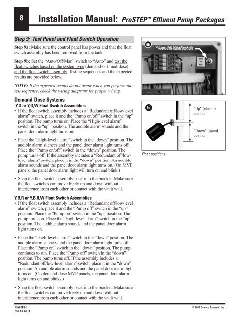
8<strong>Installation</strong> Manual: <strong>ProSTEP</strong> <strong>Effluent</strong> <strong>Pump</strong> <strong>Packages</strong>Step 9: Test Panel and Float Switch OperationStep 9a: Make sure the control panel has power and that the floatswitch assembly has been removed from the tank.Step 9b: Set the “Auto/Off/Man” switch to “Auto” and test thefloat switches based on the system type (demand-or timed-dose)and the float switch assembly. Testing sequences and the expectedresults are provided below.NOTE: If the expected results do not occur when you perform thetest sequence, check the wiring diagrams for proper wiring.Demand-Dose SystemsY,G or Y,G,W Float Switch Assemblies• If the float switch assembly includes a “Redundant off/low-levelalarm” switch, place it and the “<strong>Pump</strong> on/off” switch in the “up”position. The pump turns on. Place the “High-level alarm”switch in the “up” position. The audible alarm sounds and thepanel door alarm light turns on.• Place the “High-level alarm” switch in the “down” position. Theaudible alarm silences and the panel door alarm light turns off.Place the “<strong>Pump</strong> on/off” switch in the “down” position. Thepump turns off. If the assembly includes a “Redundant off/lowlevelalarm” switch, place it in the “down” position. An audiblealarm sounds and the panel door alarm light turns on. (On MVPpanels, the panel door alarm light will turn on and blink.)• Snap the float switch assembly back into the bracket. Make surethe float switches can move freely up and down withoutinterference from each other or contact with the vault wall.Y,B,R or Y,B,R,W Float Switch Assemblies• If the float switch assembly includes a “Redundant off/low-levelalarm” switch, place it and the “<strong>Pump</strong> off” switch in the “up”position. Place the “<strong>Pump</strong> on” switch in the “up” position. Thepump turns on. Place the “High-level alarm” switch in the “up”position. The audible alarm sounds and the panel door alarmlight turns on.• Place the “High-level alarm” switch in the “down” position. Theaudible alarm silences and the panel door alarm light turns off.Place the “<strong>Pump</strong> on” switch in the “down” position. The pumpcontinues to run. Place the “<strong>Pump</strong> off” switch in the “down”position. The pump turns off. If the assembly includes a“Redundant off/low-level alarm” switch, place it in the “down”position. An audible alarm sounds and the panel door alarm lightturns on. (On demand-dose MVP panels, the panel door alarmlight turns on and blinks.)• Snap the float switch assembly back into the bracket. Make surethe float switches can move freely up and down withoutinterference from each other or contact with the vault wall.NIM-EPS-1Rev 2.4, 02/139b9bFloat positions“Auto-Off-Man”switch“Up” (closed)position“Down” (open)position© 2013 Orenco Systems ® Inc.