AdvanTex® AX-MAX Design Criteria - Dauphin Environmental ...
AdvanTex® AX-MAX Design Criteria - Dauphin Environmental ...
AdvanTex® AX-MAX Design Criteria - Dauphin Environmental ...

You also want an ePaper? Increase the reach of your titles
YUMPU automatically turns print PDFs into web optimized ePapers that Google loves.
<strong>Design</strong> Aid<br />
AdvanTex ® <strong>AX</strong>-M<strong>AX</strong> <strong>Design</strong> <strong>Criteria</strong><br />
For Residential, Commercial, Municipal, and Mobile Applications<br />
Standard System Description<br />
The AdvanTex <strong>AX</strong>-M<strong>AX</strong> ® Treatment System is a multiple-pass, packed-bed, aerobic wastewater treatment technology specifically<br />
designed and engineered for long-term processing of domestic-strength wastewater to “better than secondary” treatment standards.<br />
It features the same outstanding textile filter performance as AdvanTex multi-pod configurations, but in a fully pre-engineered, complete<br />
package. Because it has a streamlined system configuration and few components, the <strong>AX</strong>-M<strong>AX</strong> requires little operation and<br />
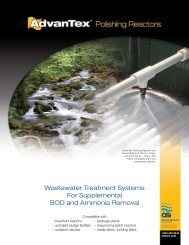
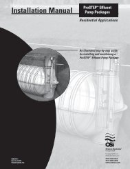
maintenance. <strong>AX</strong>-M<strong>AX</strong> systems are ideally suited for most municipal applications or residential developments. Figure 1 shows an<br />
optional layout of an <strong>AX</strong>-M<strong>AX</strong> configured as an advanced secondary treatment facility (primary treatment and dispersal not shown).<br />
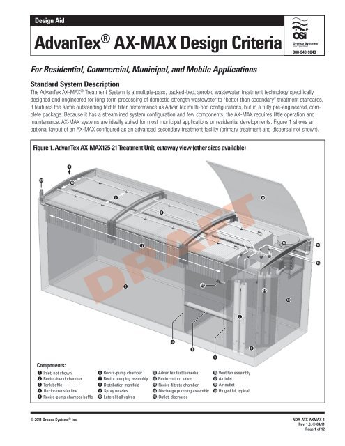
Figure 1. AdvanTex <strong>AX</strong>-M<strong>AX</strong>125-21 Treatment Unit, cutaway view (other sizes available)<br />
17<br />
Components:<br />
1<br />
2<br />
3<br />
4<br />
5<br />
1<br />
10<br />
Inlet, not shown<br />
Recirc-blend chamber<br />
Tank baffle<br />
Recirc-transfer line<br />
Recirc-pump chamber baffle<br />
9<br />
2<br />
11<br />
6 Recirc-pump chamber<br />
7 Recirc pumping assembly<br />
8 Distribution manifold<br />
9 Spray nozzles<br />
10 Lateral ball valves<br />
8<br />
DRAFT<br />
3<br />
11 AdvanTex textile media<br />
12 Recirc-return valve<br />
13 Recirc-filtrate chamber<br />
14 Discharge pumping assembly<br />
15 Outlet, discharge<br />
© 2011 Orenco Systems ® Inc. NDA-ATX-<strong>AX</strong>M<strong>AX</strong>-1<br />
Rev. 1.0, © 04/11<br />
Page 1 of 12<br />
4<br />
12<br />
5<br />
16 Vent fan assembly<br />
17 Air inlet<br />
18 Air outlet<br />
19 Hinged lid, typical<br />
7<br />
6<br />
19<br />
14<br />
16<br />
13<br />
18<br />
15
AdvanTex <strong>AX</strong>-M<strong>AX</strong> <strong>Design</strong> <strong>Criteria</strong> (cont.)<br />
Specifications and Typical Operation Summary<br />
• Domestic-strength flows up to 1 MGD capacity<br />
• Re-use capable<br />
• Low level nutrient capability<br />
• Capital costs: $7 - $12 USD per treated gallon; installed<br />
(secondary treatment only)<br />
• Power requirements: 15 hp per 0.1 MGD<br />
• Electrical consumption: 1-2 kWh/1000 gpd<br />
• Average hydraulic loading rate: 25 gpd/ft 2<br />
Treatment Process: Standard<br />
AdvanTex <strong>AX</strong>-M<strong>AX</strong> systems are typically integrated into multi-stage treatment facilities incorporating sludge and scum segregation, anaerobic<br />
digestion, and flow equalization; filtration and aerobic digestion; and disinfection and final discharge for dispersal or reuse.<br />
During the anaerobic treatment stage, organic matter segregates into sludge and scum layers, which undergo digestion by typical anaerobic<br />
processes. This stage is capable removing more than 60% of suspended solids and organic strength. In many cases, the <strong>AX</strong>-M<strong>AX</strong> is preceded<br />
by an effluent sewer, but it can be configured to receive domestic wastewater from other collection systems as well.<br />
During the aerobic treatment stage, Orenco’s proven AdvanTex treatment process provides aerobic oxidation and digestion for both organic<br />
and nutrient reduction. Incoming effluent from the primary treatment chamber enters the recirc-blend chamber where the influent is blended<br />
and diluted with filtrate from the AdvanTex system before being dosed onto the AdvanTex filter by the recirc pumps. The recirculation pumps<br />
transport the effluent to a distribution manifold above the AdvanTex filter. Effluent percolates down through the textile media, where organic and<br />
inorganic matter is treated by naturally occurring heterotrophic & autotrophic microorganisms that populate the filter. These microbes colonize<br />
down through the media relative to the degree of organic and nutrient treatment occurring. Typically, no outside chemicals are necessary for<br />
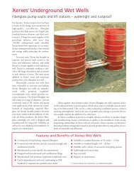
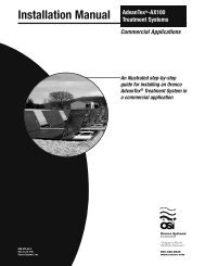
Figure 2. Typical Flow Pattern, AdvanTex <strong>AX</strong>-M<strong>AX</strong> Treatment Unit (<strong>AX</strong>-M<strong>AX</strong>125-21 shown)<br />
1 Filtered effluent from collection system enters recirc-blend chamber.<br />
2 Effluent from the recirc-blend chamber flows through the recirc-transfer line into the recirc-pump chamber.<br />
3 Recirc pumps energize spray nozzles in the manifold.<br />
4 Effluent percolates through media (not shown) and is split between the recirc-blend and recirc-filtrate chambers.<br />
5 Recirc-return valve allows one-way flow from recirc-filtrate chamber during low-use periods.<br />
6 Recirc-filtrate chamber provides tertiary treatment (where required) and storage before dispersal.<br />
NDA-ATX-<strong>AX</strong>M<strong>AX</strong>-1<br />
Rev. 1.0 © 04/11<br />
Page 2 of 12<br />
1<br />
Flow path:<br />
Nozzle spray pattern<br />
4<br />
• Peak hydraulic loading rate: 50 gpd/ft 2<br />
• Average organic loading rate: 0.04 lbs BOD/ft 2 · day<br />
• Average nitrogen loading rate: 0.017 lbs N/ft 2 · day<br />
• Recirc-blend ratio: 4:1<br />
• Dosing (“ON”) times: 60 to 90 seconds<br />
• Rest (“OFF”) times: 4 to 120 minutes<br />
• Dosing frequencies: 12 to 72 doses per day<br />
DRAFT<br />
Recirc-blend chamber<br />
Recirc-filtrate chamber<br />
5<br />
2<br />
3<br />
© 2011 Orenco Systems ® Inc.<br />
6<br />
Recirc<br />
pump<br />
chamber
AdvanTex <strong>AX</strong>-M<strong>AX</strong> <strong>Design</strong> <strong>Criteria</strong> (cont.)<br />
effluent and solids reduction, though systems requiring ammonia reduction may need alkalinity adjustments. The flow of filtered effluent is<br />
mechanically divided between the recirc-blend chamber and the recirc-filtrate chamber via a tank baffle; the liquid levels within the recircblend<br />
chamber and the recirc-filtrate chamber are controlled by the recirc-return valve. During extended periods of low forward flow, 100% of<br />
the treated effluent is returned to the recirc-blend chamber. A final pass section of the AdvanTex treatment system provides the final polishing<br />
of the effluent prior to entering the recirc-filtrate chamber.<br />
During the final stage, several treatment, disinfection, and discharge options are available. Post-aeration, post-nitrate reduction, tertiary filtration,<br />
disinfection, and/or final discharge storage are all possible uses of the final dosing chamber. The dispersal method can be designed for<br />
batch or continuous flow, with gravity or pump discharge options available. <strong>AX</strong>-M<strong>AX</strong> units can be buried below grade or set above ground. An<br />
example of the typical flow pattern for a standard <strong>AX</strong>-M<strong>AX</strong> application is shown in Figure 2.<br />
System Requirements: Typical Wastewater Influent Strength<br />
Wastewater strengths are expected to remain within typical influent limits as shown in Table 1. For higher waste strength applications, consult<br />
Orenco or an authorized AdvanTex Dealer. If the collection system is something other than an effluent sewer, then a primary treatment<br />
system will need to be incorporated into the treatment facility design. The <strong>AX</strong>-M<strong>AX</strong> can be designed to enhance other processes as well,<br />
such as stressed package plants, membranes, advanced nutrient removal, or wetlands.<br />
System Requirements: Recommended Primary Treatment<br />
Primary treatment for the <strong>AX</strong>-M<strong>AX</strong> must be capable of meeting the requirements listed in Table 1. The primary stage of the <strong>AX</strong>-M<strong>AX</strong> should<br />
incorporate a Biotube ® effluent filter, which prevents solids greater than 1 ⁄8-inch (3-mm) from passing through to the second stage. Although<br />
pre-processing of effluent is not usually required, some applications may benefit from pre-treatment, screening, and trash compacting using<br />
packaged sewage receiving stations.<br />
Table 1. Typical Commercial AdvanTex Influent Wastewater Strength*<br />
Characteristic Average (mg/L) † Weekly Peak (mg/L) Rarely Exceed (mg/L)<br />
BOD 5 150 250 500<br />
DRAFT<br />
TSS 40 75 150<br />
TKN 65 75 150<br />
G&O 20 25 30<br />
pH 7 6.5 to 7.5 6 to 9<br />
Alkalinity 250 150 ‡ 100 ‡<br />
* Wastewater strength characteristics (primary treated) entering the recirc-blend chamber of an AdvanTex <strong>AX</strong>-M<strong>AX</strong> Treatment System are considered “typical strength” when they<br />
fall within the expected ranges shown above.<br />
† Commercial systems will occasionally vary in strength based upon changes in flow characteristics or ownership. As the average influent strength approaches 80% of the weekly<br />
peak levels, consideration must be given to providing supplemental pre-treatment, additional treatment units, or process oversight.<br />
‡ Wastewater alkalinity should rarely drop below these levels if nitrogen reduction is necessary.<br />
Retention times of several days are built into the primary treatment system to provide the best possible settling and digestion, with<br />
sufficient solids retention time to ensure that long-term biosolids digestion and reduction are maximized, with minimal energy cost.<br />
Reductions in cBOD 5 and TSS are typically between 50-90% through the first stage of treatment.<br />
Alternative primary treatment devices may be appropriate for flows over 20,000 gpd (75,708 L/day) or for higher-strength applications.<br />
For higher-strength applications, a pre-treatment aeration device can be added to aid in BOD removal prior to secondary treatment.<br />
Contact Orenco to discuss alternative options for primary treatment.<br />
System Requirements: Recirculation-Blend Tankage<br />
Effluent from the primary treatment chamber discharges to the recirc-blend chamber, where it blends with the filtrate recirculating back to the<br />
recirc-blend chamber. The filtrate dilutes the primary concentrations by the rate at which the recirculation-blend ratio (R b ) is set. The recircblend<br />
chamber is typically sized to equal the actual average flow (Q a ). A larger chamber may be recommended based on the expected organic<br />
or peak design hydraulic loads, enhanced nitrogen reduction, or to accommodate special surge capacities or operator response capabilities.<br />
© 2011 Orenco Systems ® Inc. NDA-ATX-<strong>AX</strong>M<strong>AX</strong>-1<br />
Rev. 1.0, © 04/11<br />
Page 3 of 12
AdvanTex <strong>AX</strong>-M<strong>AX</strong> <strong>Design</strong> <strong>Criteria</strong> (cont.)<br />
System <strong>Design</strong> Loading Rates: Standard<br />
Multi-pass systems, such as the <strong>AX</strong>-M<strong>AX</strong>, are capable of sustaining greater loading capacities than single-pass systems because<br />
hydraulic, biological, and chemical surges are blended and diluted with a portion of the aerobically treated filtrate. The continual recirculation<br />
and intermittent dosing to the media ensures a moist environment and stable diet for the biota. The critical factors in controlling<br />
the environment are the recirculation ratio and time-controlled dosing.<br />
Orenco’s suggested design loading rates are based on typical per capita flow rates and average influent strength characteristics as listed<br />
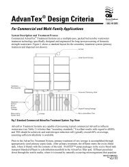
in Table 1. The <strong>AX</strong>-M<strong>AX</strong> Treatment System’s packed bed media is configured in the same manner as our ANSI/NSF Standard 40 Class I<br />
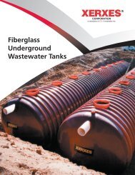
treatment units. Figure 3 shows ANSI/NSF testing results for average performance at the 95% confidence level.<br />
The base nominal AdvanTex hydraulic loading rate (HLR) is 25 gpd/ft 2 with a base organic loading rate (OLR) of 0.04 lbs BOD/ft 2 · day. At<br />
these loading rates, “actual” design criteria targets a 5/5 effluent quality in the discharge effluent. Effluent quality may be projected at a<br />
95% confidence level relative to the HLR. Peak HLR’s of 50 gpd/ft 2 or peak OLR’s of 0.08 lbs BOD/ft 2 · day can be handled for short periods<br />
of time with little effect on performance. Higher loading rates may be applicable relative to higher discharge limits or sufficient operating<br />
documentation, but normally should be limited to 50 gpd/ft 2 or lower at the typical average characteristics presented in Table 1. A thorough<br />
evaluation of all of the typical wastewater characteristics will guide design limits. High oil and grease concentrations may require some pretreatment<br />
to ensure maintenance frequencies are not excessive. Hydraulic capacities for standard <strong>AX</strong>-M<strong>AX</strong> models are provided in Table 2.<br />
Table 2. Standard Hydraulic Capacities: For Domestic Strength Wastewater<br />
NDA-ATX-<strong>AX</strong>M<strong>AX</strong>-1<br />
Rev. 1.0 © 04/11<br />
Page 4 of 12<br />
Model Average Hydraulic Capacity (gpd) Peak Hydraulic Capacity (gpd) Tank Volume (gallons)<br />
<strong>AX</strong>-M<strong>AX</strong>075-14 1,875 3,750<br />
<strong>AX</strong>-M<strong>AX</strong>100-14 2,500 5,000<br />
<strong>AX</strong>-M<strong>AX</strong>125-21 3,125 6,250<br />
<strong>AX</strong>-M<strong>AX</strong>150-21 3,750 7,500<br />
<strong>AX</strong>-M<strong>AX</strong>175-28 4,375 8,750<br />
<strong>AX</strong>-M<strong>AX</strong>200-28 5,000 10,000<br />
<strong>AX</strong>-M<strong>AX</strong>225-35 5,625 11,250<br />
<strong>AX</strong>-M<strong>AX</strong>250-35 6,250 12,500<br />
<strong>AX</strong>-M<strong>AX</strong>275-42 6,875 13,750<br />
<strong>AX</strong>-M<strong>AX</strong>300-42 7,500 15,000<br />
Capacities are based on domestic-strength waste. For commercial-strength applications, such as restaurants, wineries, or commercial facilities, see Appendix A<br />
System <strong>Design</strong> Loading Rates: Nitrogen Reduction<br />
Nitrogen is a nutrient, and is essential to plant and microbial development and growth. In most wastewater, however, there is more nitrogen<br />
than can be assimilated into cell tissue. The removal of excess nitrogen is accomplished in two conversion steps, nitrification and<br />
denitrification. In the first step (nitrification), ammonia (NH 3 -N) is oxidized biologically to nitrate (Nitrite NO 2 -N and then NO 3 -N). In the<br />
second step (denitrification), nitrate (NO 3 -N) is reduced to nitrogen gas (Typically N 2 ), which is released harmlessly to the atmosphere.<br />
Total nitrogen (TN) is the sum of organic and ammonia nitrogen, nitrate nitrogen, and nitrite nitrogen:<br />
or<br />
TN = ON + NH 3 -N + NO 2 -N + NO 3 -N<br />
TN = TKN-N + NO 2 -N + NO 3 -N<br />
DRAFT<br />
Nitrogen removal (or “nitrification/denitrification”) is a biochemical process in which ammonia is oxidized to nitrate (nitrification) (2NH 3 converts<br />
to 2NO 3 + 2H 2 O) and then nitrate is reduced through bacterial action (denitrification) (10NO 3 converts to 5N 2 +3H 2 O+10OH) to nitrogen gas.<br />
© 2011 Orenco Systems ® Inc.
AdvanTex <strong>AX</strong>-M<strong>AX</strong> <strong>Design</strong> <strong>Criteria</strong> (cont.)<br />
Total nitrogen reduction in the standard configuration will typically exceed 60 percent (with no special or supplemental process features).<br />
Using an alternative configuration, total nitrogen reduction can exceed 80 percent, depending on wastewater strength and other characteristics<br />
such as BOD 5 , grease and oils, pH, tankage (HRT), temperature, and alkalinity concentrations.<br />
The first phase of nitrification (conversion of ammonia to nitrite) liberates hydrogen ions into the solution, which lowers the pH levels,<br />
causing the influent alkalinity to be consumed. Consequently, nitrification can be inhibited if the natural buffering capacity (alkalinity) is<br />
too low. On a theoretical basis, 7.14 mg/L of alkalinity as CaCO 3 is needed to nitrify 1 mg/L of NH 4 + .<br />
For nitrogen-sensitive areas requiring greater than 99% ammonia reduction or 65% total nitrogen reduction, the recirc-blend chamber<br />
may be sized greater than the actual average flow. Pre-aeration tanks, pre-anoxic tanks, post-anoxic reactors, chemical feed devices,<br />
post-aeration devices, and/or post-anoxic treatment devices may also be necessary depending on specific limits. The typical hydraulic<br />
loading rate may need adjustment if the expected influent organic load is higher than domestic strength or the incoming ammonia levels<br />
are above 75 mg/L. For more information on nitrogen reduction, contact Orenco.<br />
Recirculation-Blend Ratios and Timer Settings<br />
The Recirculation Ratio (R b ) is defined as the ratio of the daily flow returned (Q r ) to the recirc-chamber to blend with the daily inflow<br />
(influent or forward) wastewater flow (Q i ) as shown in the following expression:<br />
where:<br />
R b = Q r / Q i<br />
Q r = R b × Q i<br />
R b is the recirculation (recirc-blend) ratio.<br />
Q r is the daily flow returned to the recirc-blend chamber, in gpd or L/day.<br />
Q i is the daily inflow (or forward flow), in gpd or L/day<br />
Typical operating recirculation-blend ratios will vary between 2:1 to 6:1, and the system’s “OFF” time varies as a function of the recirc-blend<br />
ratio. AdvanTex <strong>AX</strong>-M<strong>AX</strong> controls are initially set to a 4:1 recirc-blend ratio, and initial timer settings are established based on the expected<br />
average daily flow, influent organic, total nitrogen, pH, and alkalinity levels. If or when flows vary significantly, the control panel features automatically<br />
adjust the timer settings based on predetermined parameters.<br />
DRAFT<br />
The function of the Rb is as critical to process management for multiple-pass attached-growth packed bed filter systems as return sludge,<br />
waste sludge, and air management are to suspended-growth processes. Proper management of the Rb assures aeration and wetting needs,<br />
but most importantly it establishes equilibrium with respect to the desired endogenous respiration rate by maintaining food-to-microorganism<br />
(F/M) ratios relative to influent hydraulic and biological loads. The recirculation ratio is well documented in textbooks and design manuals.<br />
It’s important to understand that there are both high and low R b limits to watch for. Higher ratios may be preferred to prevent odor problems,<br />
but generally should not exceed 6 or 7; ratios of 2 or 3 – with normal strength influent – are typically sufficient for controlling odors and<br />
providing treatment.<br />
A high R b can have many adverse effects on the biology, chemistry, and performance of a system. It can deplete the base alkalinity concentration<br />
sufficiently to cause the pH to fall below acceptable levels. The ecosystem then becomes especially suited for filamentous microbes, which<br />
tend to cluster and overpopulate on the pump screens, accelerating the system’s cleaning needs. In addition, a high R b doesn’t allow sufficient<br />
time for filtrate dissolved oxygen (DO) levels to deplete within the recirc-blend chamber. Dissolved oxygen depletion is necessary for effective<br />
denitrification. So a high R b can inhibit denitrification and cause greater nitrate concentrations to pass through the system. Not only can an<br />
excessively high R b increase maintenance demands and degrade effluent quality, it also consumes more energy than necessary. A high R b can<br />
cause process degradation, regardless of the growth process (suspended or attached) when not properly controlled.<br />
An excessively low R b can have adverse effects as well. A low R b may not provide sufficient aeration for organic or nutrient demand, causing<br />
insufficient treatment. In addition, low R b can lead to anaerobic conditions that lead to odor control issues.<br />
© 2011 Orenco Systems ® Inc. NDA-ATX-<strong>AX</strong>M<strong>AX</strong>-1<br />
Rev. 1.0, © 04/11<br />
Page 5 of 12
AdvanTex <strong>AX</strong>-M<strong>AX</strong> <strong>Design</strong> <strong>Criteria</strong> (cont.)<br />
Dosing Frequency - Cycle Time (DF - CT)<br />
The dosing frequency is typically reported as the number of doses or dosing events/day, but more specifically represents the time span<br />
between doses (the time measure is generally in minutes) or, in control terminology, cycle time (CT). There are two components to the dosing<br />
frequency: “ON” dosing time and the “OFF” resting time, as shown in the following expression:<br />
NDA-ATX-<strong>AX</strong>M<strong>AX</strong>-1<br />
Rev. 1.0 © 04/11<br />
Page 6 of 12<br />
CT = DF = T d + T r<br />
and also:<br />
DF = 1440 min per day/dpd<br />
dpd = Q f / T d Q d<br />
dpd = (R b + 1) Q i / T d Q d<br />
DF = 1440 T d Q d / (R b + 1) Q i<br />
R b = (1440 T d Q d – 1) / Q i (T r + T d )<br />
where:<br />
CT is the dose cycle time in minutes<br />
DF is the dose frequency time in min/dose<br />
dpd is the number of doses per day<br />
T d is the dose time in minutes (“ON”)<br />
T r is the rest time in minutes (“OFF”)<br />
Q f is the total flow through the recirculation tank (Q i + Q r )<br />
Q d is the dosing rate to the filter, in gpm (5-6 gpm per nozzle)<br />
The dosing frequency is related to the R b as well as to particular features of the media, such as its texture, void ratio, water-holding capacity<br />
etc. Considerable academic work has been done to establish relative dosing frequencies for various media. It’s well established that small<br />
frequent doses improve filter performance. Increasing the dosing frequency (number of occurrences over a given time period) reduces the<br />
volume of wastewater applied per dose and increases coliform removal (Mohammed, 1991).<br />
The dosing time is the “ON” time span. The dosing time is related to the application dose rate, in gpm/ft 2 , and the water holding capacity<br />
(WHC) of the filter media. Critical factors include keeping the applied dose to a fraction of the water holding capacity of the media and within<br />
the typical Rb limits based on influent flows, food values, and other constituents. Standard “ON” times are 1 to 1.5 minutes.<br />
The resting time is the “OFF” time span. The resting time is primarily dependent on the recirculation ratio, “ON” time, and the influent flows.<br />
Being the dependent variable, the resting time is typically determined as shown in the following expression:<br />
or<br />
T r = DF - T d<br />
T r = [ 1440 T d Q d / (R b + 1) Q i ] – T d<br />
The critical issue with the resting period is that it not be excessively long. One dose per 90 to 120 minutes is typically sufficient for maintaining<br />
wetting of the biomass during low flow periods. By adjusting the R b , the dilution and blend concentrations within the recirc-blend chamber<br />
can be balanced, as shown by the following expression.<br />
or<br />
where:<br />
or<br />
Q i S i + Q r S e =Q r+i S b<br />
Q i S i + Q i R b S e = (R b + 1) Q i S b<br />
S i + R b S e = (R b + 1) S b<br />
Q r+i is the daily filter hydraulic load, in gpd<br />
Qr+i = Qf = (Rb + 1) Qi where:<br />
DRAFT<br />
Q r is the daily flow returned to the recirc-blend chamber, in gpd<br />
S i is the inflow substrate concentration, in mg/L<br />
S e is the filtrate substrate concentration, in mg/L<br />
S b is the blended substrate concentration, in mg/L<br />
© 2011 Orenco Systems ® Inc.
AdvanTex <strong>AX</strong>-M<strong>AX</strong> <strong>Design</strong> <strong>Criteria</strong> (cont.)<br />
By varying R b within the limits of the application’s wastewater characteristics, optimization of the HRT and substrate concentrations within<br />
the recirc-blend chamber can be accomplished. Biological respiration rates tend to adjust according to the available food and oxygen.<br />
Therefore, to ensure the best performance and sustain the most efficient and effective working environment, the substrate equations<br />
(above and below) are used to establish programmed timer settings to maintain an R b within an acceptable range. The recirc-blend<br />
chamber’s blended substrate concentration may be determined directly by the following expression:<br />
S b = (S i + R b S e ) / (R b +1)<br />
The dose frequency and recirculation ratio are directly related to and dependent on each other, but only one at a time can be the independent<br />
variable. Typical design practice calls for maintaining a recirc-ratio within a bandwidth making it (the recirc-ratio) the controlling or independent<br />
variable, thus leaving the dosing frequency as the dependent variable. Within the expression for the dosing frequency are the dosing period<br />
and resting period. The dosing period (T d ) is governed by the characteristics in the make-up of the media and must be kept within a narrowly<br />
limited range. The resting period (T r ) has the greatest flexibility and is, therefore, the most desirable choice for the dependent variable.<br />
Figure 3.<br />
Effluent Quality vs. Hydraulic Loading Rates*<br />
(ANSI/NSF Standard 40 and Other Third Party Testing Results)<br />
60<br />
50<br />
40<br />
30<br />
20<br />
10<br />
0<br />
0 407 815 1222 1630 2037 2445 (L/day/m2 )<br />
0 10 20 30 40 50 60 (gpd/ft2 UC Davis<br />
489 L/day/m<br />
)<br />
2<br />
UC Davis<br />
489 L/day/m<br />
5 mo.<br />
2<br />
NSF<br />
5 mo.<br />
1186 L/day/m2 NSF<br />
1186 L/day/m<br />
6 mo.<br />
2<br />
NovaTec<br />
1968 L/day/m<br />
6 mo.<br />
2<br />
NovaTec<br />
1968 L/day/m<br />
4 mo.<br />
2<br />
NovaTec<br />
2445 L/day/m<br />
4 mo.<br />
2<br />
NovaTec<br />
2445 L/day/m<br />
10 mo.<br />
2<br />
10 mo.<br />
60<br />
50<br />
40<br />
30<br />
20<br />
10<br />
0<br />
0 407 815 1222 1630 2037 2445 (L/day/m2 )<br />
0 10 20 30 40 50 60 (gpd/ft2 UC Davis<br />
489 L/day/m<br />
)<br />
2<br />
UC Davis<br />
489 L/day/m<br />
5 mo.<br />
2<br />
5 mo.<br />
NSF<br />
1186 L/day/m2 NSF<br />
1186 L/day/m<br />
6 mo.<br />
2<br />
6 mo.<br />
NovaTec<br />
1968 L/day/m2 NovaTec<br />
1968 L/day/m<br />
4 mo.<br />
2<br />
NovaTec<br />
2445 L/day/m<br />
4 mo.<br />
2<br />
NovaTec<br />
2445 L/day/m<br />
10 mo.<br />
2<br />
10 mo.<br />
System Performance and Typical Effluent<br />
Quality<br />
AdvanTex Treatment Systems are capable of processing typical<br />
domestic strength wastewater (see Table 1) to “better than secondary<br />
treatment standards.” With additional components they can meet more<br />
advanced treatment levels with little additional operation and maintenance.<br />
Standard systems achieve
AdvanTex <strong>AX</strong>-M<strong>AX</strong> <strong>Design</strong> <strong>Criteria</strong> (cont.)<br />
AdvanTex <strong>AX</strong>-M<strong>AX</strong> Control System<br />
The method in which the effluent is loaded onto the AdvanTex filter is critical to the successful performance of the <strong>AX</strong>-M<strong>AX</strong> Treatment<br />
System. Over the past three decades, timer-controlled applications have proven to play an essential role in optimizing the performance of<br />
both fixed and suspended growth biological systems. A timer-controlled pump in the recirc-blend chamber periodically doses effluent to a<br />
distribution system on top of the AdvanTex filter media. Each time the filter is dosed, effluent slowly percolates through the filter media and is<br />
treated by naturally-occurring microorganisms that populate the filter. During periods of high flow, a timer override float will temporarily adjust<br />
the timer settings to process the additional flow. The controller can also be programmed to change to an energy economy mode during<br />
extended periods of low inflow.<br />
A telemetry-based panel — which can be connected to a land line, cellular service, internet, or satellite service — controls all equipment.<br />
Remote telemetry control panels are an integral part of all commercial AdvanTex Treatment System equipment packages. The remote<br />
telemetry feature provides real-time operator monitoring and control over system components, as well as data collection of key operational<br />
parameters and events. If additional equipment for pretreatment, tertiary treatment, or disinfection are required, the controls for each component<br />
can easily be incorporated into the telemetry control panel. This also allows the manufacturer to contact the panel directly to assist the<br />
operator in system evaluation and troubleshooting or to manually override operations. Remote telemetry control panels also provide additional<br />
alarm functions to automatically page the operator in the event that trend data indicate potential problem conditions (e.g. high flows). Orenco<br />
control panels can also integrate into existing SCADA systems.<br />
Surge Volume<br />
<strong>AX</strong>-M<strong>AX</strong> tankage design is consistent with that of other packed bed filters. Flow equalization should be designed into the primary tankage<br />
with controlled (metered) feed to the recirc-blend chamber. If surging needs to be done in the recirc-blend chamber, then sizing and timer<br />
controls will be programmed to optimize performance and surge capacity. Churches, schools, destination resorts, dining establishments,<br />
and assembly halls are typical applications where weekly surge control practices provide optimum filter sizing.<br />
Pumping Equipment<br />
The integrated treatment package includes one or more Orenco pump packages. Typically, duplex pumps are used to energize the distribution<br />
manifold and are specified for redundancy in each of the textile treatment channels. This can be accomplished with a single pump per<br />
channel in larger flow applications. Pump models will vary based on number of units, flow path, and system configuration.<br />
Venting Equipment<br />
<strong>AX</strong>-M<strong>AX</strong> Treatment Systems typically come with an incorporated active vent system. With the active vent system, air changes occur at<br />
least once every 2 hours. The active vent system is available with an activated charcoal filter for increased odor reduction. One ventilation<br />
assembly is required per four <strong>AX</strong>-M<strong>AX</strong> units.<br />
Sludge Handling Equipment<br />
AdvanTex systems can be equipped with a sludge removal pump that can be activated manually if sludge needs to be purged from the<br />
primary chamber. Primary chamber sizing is roughly one-three days HRT based on actual flow, influent characteristics, and pre-treatment<br />
NDA-ATX-<strong>AX</strong>M<strong>AX</strong>-1<br />
Rev. 1.0 © 04/11<br />
Page 8 of 12<br />
DRAFT<br />
devices; sludge purging may be required. Sludge is typically about 1-5% solids and may require dewatering and lime treatment prior to land<br />
application. Solids removal devices may be placed prior to the primary chamber to reduce overall chamber sizes. Solids removal devices will,<br />
however, require regular maintenance and/or disposal of solids cake on a regular frequency.<br />
Supplemental Process Equipment<br />
Additional processes can be included in the design of an <strong>AX</strong>-M<strong>AX</strong>, such as sewage headworks, primary treatment, septage handling, solids<br />
handling, pH/alkalinity adjustment, carbon feed, pre- or post-aeration, disinfection, advanced nitrogen removal, phosphorus removal,<br />
turbidity removal, disinfection, and dispersal.<br />
Climate Considerations and System Enclosures<br />
<strong>AX</strong>-M<strong>AX</strong> systems are designed to withstand climates ranging from temperatures of -60° F (-51°C) to 125° F (52° C). Units are constructed<br />
with 4-inch-thick foam cells providing an estimated 26R insulation value. <strong>AX</strong>-M<strong>AX</strong> systems are also available with an optional build-on control<br />
module, to provide a climate-controlled environment for easy operation and maintenance.<br />
© 2011 Orenco Systems ® Inc.
AdvanTex <strong>AX</strong>-M<strong>AX</strong> <strong>Design</strong> <strong>Criteria</strong> (cont.)<br />
Alternatively, the <strong>AX</strong>-M<strong>AX</strong> can be enclosed in a building for maximum privacy, efficiency, and climate control. <strong>AX</strong>-M<strong>AX</strong> systems are compatible<br />
with a variety of enclosure types. Typical construction materials for the enclosure include a combination of concrete, fiberglass, steel and<br />
wood.<br />
Energy Consumption<br />
Orenco’s <strong>AX</strong>-M<strong>AX</strong> systems and their components are designed in a manner that allows for highly cost-effective operation for the life of the<br />
system. Unlike most other aerobic treatment systems, AdvanTex has low energy consumption due to the intermittent use of low horsepower,<br />
high-head turbine pumps and a small ventilation fan. With lower power costs and lifecycle costs than many of the available alternatives,<br />
<strong>AX</strong>-M<strong>AX</strong> is an ideal option for “green” projects. For information on obtaining LEED credits, please visit our website at www.orenco.com.<br />
Sample power consumption for 50,000 gpd (peak design flow) <strong>AX</strong>-M<strong>AX</strong> system with an average flow of 25,000 gpd:<br />
Assumptions:<br />
Four sets of ¾-hp duplex pumps, each operating at 15% of available hours annually<br />
Pump “ON” time of 1 min, Pump “OFF” time of 6 min. 1/(6 + 1) = 15% (230 V, 10.1 A, 1-Phase)<br />
One 1.4-A (115 V) ventilation fan operating at 100% of available hours annually<br />
Energy cost of 0.10 $/kWh (USD)<br />
Energy cost, pumps:<br />
[ 4 × (230 V × 10.1 A) × 15% ] / 1000 = 1.380 kWh/h<br />
1.380 kWh/h × 8760 hr/year × 0.10 $/kWh = $1209 (USD), annually<br />
Energy cost, ventilation fan:<br />
[ 1 x (115 V x 1.4 A) × 100% ]/1000 = 0.161 kWh/h<br />
0.161 kWh/h × 8760 hr/year × 0.10 $/kWh = $141 (USD) annually<br />
Energy cost, control panel:<br />
[1 x (115 V x .3 A) x 100%]/1000 = 0.0345 kWh/h<br />
0.0345 kWh/h × 8760 hr/year × 0.10 $/kWh = $30 (USD) annually<br />
Total kWh/h = 1.58 kWh/h<br />
Total kWh/d = 37.81 kWh/d<br />
DRAFT<br />
Total kWh/year = 13,801.4 kWh/year<br />
Total estimated annual energy cost = $1209 + $141 + $30 = $1380 (USD), annually<br />
In some cases, efficiencies may allow for the reduction of recirculation ratios, resulting in even lower energy consumption, as well as process<br />
configuration that would reduce overall electrical equipment and power consumption. This includes the operation of surge pumps, recirculation<br />
pumps, ventilation system components, pump controls, and discharge pumps.<br />
For custom applications, AdvanTex Treatment Systems can be designed to operate on photovoltaic (PV) systems. Power sources incorporating<br />
diesel, gasoline, or battery generators can also be custom-designed into an <strong>AX</strong>-M<strong>AX</strong> system configuration. Call Orenco for more details.<br />
Sustainability<br />
Decentralized package treatment plants and their manufacturers are not all alike. Orenco has always been committed to the long term<br />
performance and low operating cost of its treatment systems; our engineers know that design integrity and product support matter. Orenco<br />
<strong>AX</strong>-M<strong>AX</strong> Treatment Systems meet the requirements of sustainability by protecting the “triple bottom line” of social, environmental, and financial<br />
benefits. For these reasons, AdvanTex is consistently chosen by developers and municipalities looking for wastewater technology that<br />
supports their sustainability goals.<br />
© 2011 Orenco Systems ® Inc. NDA-ATX-<strong>AX</strong>M<strong>AX</strong>-1<br />
Rev. 1.0, © 04/11<br />
Page 9 of 12
AdvanTex <strong>AX</strong>-M<strong>AX</strong> <strong>Design</strong> <strong>Criteria</strong> (cont.)<br />
Operation and Maintenance<br />
The <strong>AX</strong>-M<strong>AX</strong> has a streamlined system configuration designed to achieve high effluent quality and low power consumption, with minimal<br />
maintenance requirements and low life-cycle costs. O&M activities include effluent sampling for performance data collection, as well as scheduled<br />
cleaning of effluent filters, textile sheets, laterals, and spray nozzles. In units equipped with dry-chemical feed units, regular loading of the<br />
feed hopper is necessary. For units equipped with UV disinfection, the UV bulbs require yearly replacement. Recirculation chambers typically<br />
have minimal sludge accumulations and rarely require pumping.<br />
Operationally, the module’s flexible and easily serviceable features make <strong>AX</strong>-M<strong>AX</strong> units an ideal, efficient, and effective solution for all wastewater<br />
treatment applications with typical domestic waste characteristics. The <strong>AX</strong>-M<strong>AX</strong> dependably produces high-quality effluent with no need<br />
for full-time staffing. And Its controls and telemetry features give service providers the opportunity to provide remote operational oversight as<br />
necessary.<br />
To assist in reliability and ease of maintenance, <strong>AX</strong>-M<strong>AX</strong> systems are built with rugged, dependable parts and components, designed to work<br />
together for long service lives. The replacement cycle for liquid level switches is typically five years. The replacement cycle for Orenco highhead<br />
effluent pumps and various small components in the control panel is typically 10-15 years. Orenco’s high-head effluent pumps can be<br />
rebuilt in the field with simple tools and the pump motors are easily replaced.<br />
In addition, Orenco has a dedicated, experienced Asset Management division to support wastewater assets in the field.<br />
Education<br />
Orenco provides AdvanTex <strong>Design</strong> programs for designers, engineers, and regulators. Orenco also provides regular installation and O&M<br />
trainings for contractors, operators, and users. Check with Orenco’s training department for information on upcoming courses. Training for<br />
end users can help ensure influent characteristics, chemical use, and operating practices are properly managed and maintained through<br />
an understanding of how microbial toxic thresholds can retard or inhibit performance in wastewater processes.<br />
References and Performance Data<br />
Since 1981, Orenco has been involved in thousands of commercial and community wastewater systems, providing education, design assistance,<br />
equipment, installation oversight, and operational support. References of system owners, engineers, and operators are available<br />
from Orenco. In addition, project tours are often available through the local regulatory jurisdiction or an Orenco equipment distributor. Call<br />
Orenco at 800-348-9843 or +1-541-459-4449 for more information about references or tours.<br />
NDA-ATX-<strong>AX</strong>M<strong>AX</strong>-1<br />
Rev. 1.0 © 04/11<br />
Page 10 of 12<br />
DRAFT<br />
© 2011 Orenco Systems ® Inc.
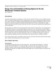
Appendix A: Primary Tank Sizing Chart<br />
AdvanTex <strong>AX</strong>-M<strong>AX</strong> <strong>Design</strong> <strong>Criteria</strong> (cont.)<br />
Facility Minimum Preferred<br />
Office/Manufacturing/Light Industrial<br />
Grease Tankage 1<br />
HRT (days)<br />
Primary Tankage 2<br />
HRT (days)<br />
Grease Tankage 1<br />
HRT (days)<br />
Primary Tankage 2<br />
HRT (days)<br />
a) restrooms only n/a 3 n/a 4<br />
Restaurant/Deli<br />
a) restrooms and kitchen 3 4 5 5<br />
Convenience Store/Gas Station<br />
a) restrooms only<br />
b) restrooms and kitchen/deli<br />
Hotel/Motel/Multiple Dwelling Units<br />
Church<br />
School<br />
a) restrooms and kitchens<br />
b) restrooms and restaurant/kitchen<br />
a) restrooms only<br />
b) restrooms and kitchen<br />
a) restrooms only<br />
b) restrooms and kitchen<br />
Dog Kennel/Veterinary Clinic<br />
RV Park<br />
Casino<br />
a) restrooms only<br />
b) restrooms and floor drains<br />
a) RV spaces<br />
b) dump station<br />
a) gaming floor<br />
b) hotel/motel<br />
c) restaurant/deli<br />
Resort/Camp<br />
a) bunk houses<br />
b) main houses<br />
c) kitchen<br />
n/a<br />
2<br />
n/a<br />
3<br />
n/a<br />
2<br />
n/a<br />
3<br />
n/a<br />
© 2011 Orenco Systems ® Inc. NDA-ATX-<strong>AX</strong>M<strong>AX</strong>-1<br />
Rev. 1.0, © 04/11<br />
Page 11 of 12<br />
3<br />
3 3<br />
3<br />
3 3<br />
2.5 + Surge 4<br />
2.5 + Surge 3,4<br />
3 + Surge 4<br />
3 + Surge 3,4<br />
DRAFT<br />
n/a<br />
n/a<br />
n/a<br />
n/a<br />
n/a<br />
3<br />
n/a<br />
n/a<br />
2<br />
3<br />
3 + Surge 3,4,5<br />
3<br />
8<br />
3<br />
3<br />
4<br />
n/a<br />
4<br />
n/a<br />
5<br />
n/a<br />
4<br />
n/a<br />
5<br />
n/a<br />
n/a<br />
n/a<br />
n/a<br />
n/a<br />
n/a<br />
5<br />
n/a<br />
4 3<br />
4<br />
4 3<br />
4 + Surge 4<br />
4 + Surge 3,4<br />
4 + Surge 4<br />
4 + Surge 3,4<br />
4<br />
4 + Surge 3,4,5<br />
1. Grease tankage HRT is based on a separate kitchen design maximum daily flow, which is integrated into the mail flow prior to the primary septic tanks.<br />
2. Primary tankage HRT is based on the sum of the design maximum daily flows from all sources.<br />
3. For facilities with restrooms and kitchen, primary tankage volume is determined by multiplying the sum of the design maximum daily flows of the restrooms and kitchen<br />
combined by the factor in the primary tankage cell.<br />
4. To determine surge volume for flow equalization purposes, please call Orenco Systems at (800) 348-9843 or +1-541-459-4449 for assistance.<br />
5. To reduce septage pumping in these and other specialized applications, we recommend using multiple tanks: The first should be small (0.5 to 0.75 HRT); subsequent tanks<br />
should provide the remaining HRT requirements.<br />
Note: Tankages are based on long-term performance satisfaction (with respect to septage removal) and nominal (minimum) to high-quality (preferred)<br />
effluent. If effluent strength is higher than the expected level or if a higher level of treatment is required, greater tankage will be necessary.<br />
To enhance total nitrogen reduction, primary tankage should be increased for AdvanTex Mode 3 systems. Contact Orenco for specifics.<br />
3<br />
3<br />
3<br />
n/a<br />
n/a<br />
4<br />
4<br />
10<br />
4<br />
4<br />
5<br />
4<br />
4<br />
4
AdvanTex <strong>AX</strong>-M<strong>AX</strong> <strong>Design</strong> <strong>Criteria</strong> (cont.)<br />
NDA-ATX-<strong>AX</strong>M<strong>AX</strong>-1<br />
Rev. 1.0 © 04/11<br />
Page 12 of 12<br />
DRAFT<br />
© 2011 Orenco Systems ® Inc.