ELECTRICAL MOTOR-GENERATOR GB2282708 - Intalek
ELECTRICAL MOTOR-GENERATOR GB2282708 - Intalek
ELECTRICAL MOTOR-GENERATOR GB2282708 - Intalek
Create successful ePaper yourself
Turn your PDF publications into a flip-book with our unique Google optimized e-Paper software.
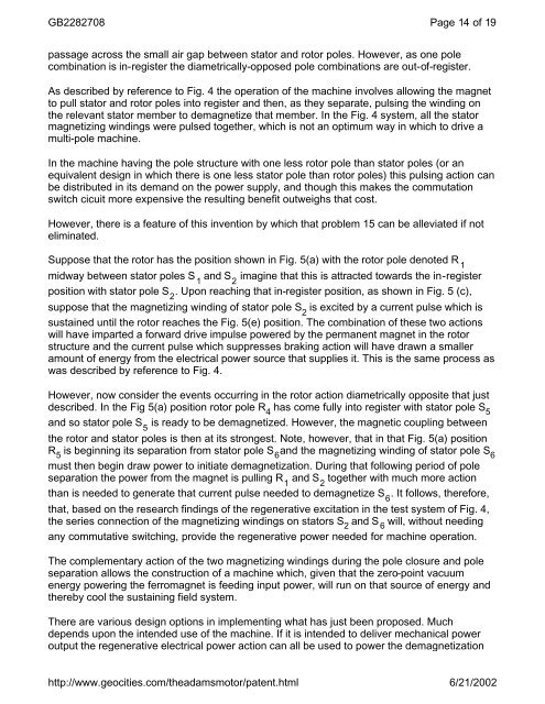
<strong>GB2282708</strong>Page 14 of 19passage across the small air gap between stator and rotor poles. However, as one polecombination is in-register the diametrically-opposed pole combinations are out-of-register.As described by reference to Fig. 4 the operation of the machine involves allowing the magnetto pull stator and rotor poles into register and then, as they separate, pulsing the winding onthe relevant stator member to demagnetize that member. In the Fig. 4 system, all the statormagnetizing windings were pulsed together, which is not an optimum way in which to drive amulti-pole machine.In the machine having the pole structure with one less rotor pole than stator poles (or anequivalent design in which there is one less stator pole than rotor poles) this pulsing action canbe distributed in its demand on the power supply, and though this makes the commutationswitch cicuit more expensive the resulting benefit outweighs that cost.However, there is a feature of this invention by which that problem 15 can be alleviated if noteliminated.Suppose that the rotor has the position shown in Fig. 5(a) with the rotor pole denoted R 1midway between stator poles S 1and S 2imagine that this is attracted towards the in-registerposition with stator pole S 2. Upon reaching that in-register position, as shown in Fig. 5 (c),suppose that the magnetizing winding of stator pole S 2is excited by a current pulse which issustained until the rotor reaches the Fig. 5(e) position. The combination of these two actionswill have imparted a forward drive impulse powered by the permanent magnet in the rotorstructure and the current pulse which suppresses braking action will have drawn a smalleramount of energy from the electrical power source that supplies it. This is the same process aswas described by reference to Fig. 4.However, now consider the events occurring in the rotor action diametrically opposite that justdescribed. In the Fig 5(a) position rotor pole R 4has come fully into register with stator pole S 5and so stator pole S 5is ready to be demagnetized. However, the magnetic coupling betweenthe rotor and stator poles is then at its strongest. Note, however, that in that Fig. 5(a) positionR 5is beginning its separation from stator pole S 6and the magnetizing winding of stator pole S 6must then begin draw power to initiate demagnetization. During that following period of poleseparation the power from the magnet is pulling R 1and S 2together with much more actionthan is needed to generate that current pulse needed to demagnetize S 6. It follows, therefore,that, based on the research findings of the regenerative excitation in the test system of Fig. 4,the series connection of the magnetizing windings on stators S 2and S 6will, without needingany commutative switching, provide the regenerative power needed for machine operation.The complementary action of the two magnetizing windings during the pole closure and poleseparation allows the construction of a machine which, given that the zero-point vacuumenergy powering the ferromagnet is feeding input power, will run on that source of energy andthereby cool the sustaining field system.There are various design options in implementing what has just been proposed. Muchdepends upon the intended use of the machine. If it is intended to deliver mechanical poweroutput the regenerative electrical power action can all be used to power the demagnetizationhttp://www.geocities.com/theadamsmotor/patent.html6/21/2002


