ELECTRICAL MOTOR-GENERATOR GB2282708 - Intalek
ELECTRICAL MOTOR-GENERATOR GB2282708 - Intalek
ELECTRICAL MOTOR-GENERATOR GB2282708 - Intalek

Create successful ePaper yourself
Turn your PDF publications into a flip-book with our unique Google optimized e-Paper software.
<strong>GB2282708</strong>Page 1 of 19<strong>ELECTRICAL</strong> <strong>MOTOR</strong>-<strong>GENERATOR</strong><strong>GB2282708</strong>DATE OF A PUBLICATION: 12.04.1995Applicant(s):Harold Aspden- SOUTHAMPTON, United KingdomRobert George Adams-New ZealandDate of Filing: 30.09.1993Application No: 9320215.8INTeL 6 :HO2K 29/0823/5223/66/I HO2K 1/27UKCL(Edition N):H2A AKC2 AKR 1 AK1O8 AK12O AK12 1 AK200 AK214R AK2 165 AK217R AK3O2B AK3O3R AK800Documents Cited:GB 0547608 A US 5258697 A US 4972112 A US 4873463 AField of Search:UK CL (Edition M) H2A AKRR AKR1 AKR6 AKR9INT CL 5 HO2K 23/62 29/08 29/10 29/12 53/00 57/00ONLINE DATABASES : WPI. CLAIMSAgent and/or Address for Service:Harold Aspden, SOUTHAMPTON, United KingdomABSTRACTAn electrodynamic motor-generator has a salient pole permanent magnet rotor interacting withsalient stator poies to form a machine operating on the magnetic reluctance principle. Theintrinsic ferromagnetic power of the magnets provides the drive torque by bringing the polesinto register whilst current pulses demagnetize the stator poles as the poles separate. In asmuch as less power is needed for stator demagnetization than is fed into the reluctance driveby the thermodynamic system powering the ferromagnetic state, the machine operatesregeneratively by virtue of stator winding interconnection with unequal number of rotor andstator poles. A rotor construction is disclosed (Fig 6, 7). The current pulse may be such as tocause replusion of the rotor poles.FIELD OF INVENTIONThis invention relates to a form of electric motor which serves a generating function in that themachine can act regeneratively to develop output electrical power or can generate mechanicalhttp://www.geocities.com/theadamsmotor/patent.html6/21/2002
<strong>GB2282708</strong>Page 2 of 19drive torque with unusually high efficiency in relation to electrical power input.The field of invention is that of switched reluctance motors, meaning machines which havesalient poles and operate by virtue of the mutual magnetic attraction and / or repulsion asbetween magnetized poles. The invention particularly concerns a form of reluctance motorwhich incorporates permanent magnets to establish magnetic polarization.BACKGROUND OF THE INVENTIONThere have been proposals in the past for machines in which the relative motion of magnetscan in some way develop unusually strong force actions which are said to result in more poweroutput than is supplied as electrical input.By orthodox electrical engineering principles such suggestions have seemed to contradictaccepted principles of physics, but it is becoming increasingly evident that conformity with thefirst law of thermodynamics allows a gain in the electromechanical power balance provided it ismatched by a thermal cooling.In this sense, one needs to extend the physical background of the cooling medium to include,not just the machine structure and the immediate ambient environment, but also the subquantumlevel of what is termed, in modern physics, the zero-point field. This is the fieldassociated with the Planck constant. Energy is constantly being exchanged as between thatactivity and coextensive matter forms but normally these energy fluctuations preserve, onbalance, an equilibrium condition so that this action passes unnoticed at the technology level.Physicists are becoming more and more aware of the fact that, as with gravitation, somagnetism is a route by which we can gain access to the sea of energy that pervades thevacuum. Historically, the energy balance has been written in mathematical terms by assigning'negative' potential to gravitation or magnetism. However, this is only a disguised way of sayingthat the vacuum field, suitably influenced by the gravitating mass of a body in the locality or bymagnetism in a ferromagnet has both the capacity and an urge to shed energy.Now, however, there is growing awareness of the technological energy generating potential ofthis field background and interest is developing in techniques for 'pumping' the couplingbetween matter and vacuum field to derive power from that hidden energy source. Suchresearch may establish that this action will draw on the 2. 7K cosmic background temperatureof the space medium through which the Earth travels at some 400 km/s. The effectcontemplated could well leave a cool vapour trail' in space as a machine delivering heat, ordelivering a more useful electrical form of energy that will revert to heat, travels with bodyEarth through that space.In pure physics terms, relevant background is of recent record in the August 1993 issue ofPhysical Review E, vol. 48, pp. 1562-1565 under the title: 'Extracting energy and heat from thevacuum', authored by D.C. Cole and H. E. Puthoff. Though the connection is not referenced inthat paper, one of its author's presented experimental evidence on that theme at an April 1993conference held in Denver USA. The plasma power generating device discussed at thatconference was the subject of U. S. Patent No. 5,018,180, the inventor of record being K. R.Shoulders.http://www.geocities.com/theadamsmotor/patent.html6/21/2002
<strong>GB2282708</strong>Page 3 of 19The invention, to be described below, operates by extracting energy from a magnetic system ina motor and the relevant scientific background to this technology can be appreciated from theteachings of E.B. Moullin, a Cambridge Professor of Electrical Engineering who was aPresident of the Institution of Electrical Engineers in U. K.That prior art will be described below as part of the explanation of the operation of theinvention.The invention presented here concerns specific structural design features of a machineadapted for robust operation, but these also have novelty and special merit in a functionaloperation. What is described is quite distinct from prior art proposals, one being a novel kind ofmotor proposed by Gareth Jones at a 1988 symposium held in Hull, Canada under theauspices of the Planetary Association for Clean Energy. Jones suggested the adaptation of anautomobile alternator which generates three-phase a. c. for rectification and use as a powersupply for the electrics in the automobile. This alternator has a permanent magnet rotor andJones suggested that it could be used, with high efficiency gain and torque performance, byoperating it as a motor with the three-phase winding circuit excited so as to promote strongrepulsion between the magnet poles and the stator poles after the poles had come intoregister. However, the Jones machine is not one exploiting the advantages of the invention tobe described, because it is not strictly a reluctance motor having salient poles on both statorand rotor. The stator poles in the Jones machine are formed by the winding configuration in aslotted stator form, the many slots being uniformly distributed around the inner circumferenceof the stator and not constituting a pole system which lends itself to the magnetic flux actionsto be described by reference to the E.B. Moullin experiment.The Jones machine operates by generating a rotating stator field which, in a sense, pushes therotor poles forward rather than pulling them in the manner seen in the normal synchronousmotor. Accordingly, the Jones machine relies on the electric current excitation of the motorproducing a field system which rotates smoothly but has a polarity pattern which is forced bythe commutation control to keep behind the rotor poles in asserting a continuous repulsivedrive.Another prior art proposal which is distinguished from this invention is that of one of theapplicants, H. Aspden, namely the subject of U.K. Patent No. 2,234,863 (counterpart U.S.Patent Serial No. (4,975,608). Although this latter invention is concerned with extractingenergy from the field by the same physical process as the subject invention, the technique foraccessing that energy is not optimum in respect of the structure or method used. Whereas inthis earlier disclosure, the switching of the reluctance drive excited the poles in their approachphase, the subject invention, in one of its aspects, offers distinct advantages bydemagnetization or reversal of magnetization in the pole separation phase of operation.There are unexpected advantages in the implementation proposed by the subject invention,inasmuch as recent research has confirmed that it requires less input power to switch off themutual attraction across an air gap between a magnet and an electromagnet than it does toswitch it on. Usually, in electromagnetism, a reversal symmetry is expected, arising fromconventional teaching of the way forward and back magnetomotive forces govern the resultingflux in a magnetic circuit. This will be further explained after describing the scope of theinvention.http://www.geocities.com/theadamsmotor/patent.html6/21/2002
<strong>GB2282708</strong>Page 4 of 19BRIEF DESCRIPTION OF THE INVENTIONAccording to one aspect of the invention, an electrodynamic motor-generator machinecomprises a stator configured to provide a set of stator poles, a corresponding set ofmagnetizing windings mounted on the stator pole set, a rotor having two sections each ofwhich has a set of salient pole pieces, the rotor sections being axially spaced along the axis ofrotation of the rotor, rotor magnetization means disposed between the two rotor sectionsarranged to produce a unidirectional magnetic field which magnetically polarizes the rotorpoles, whereby the pole faces of one rotor section all have a north polarity and the pole facesof the other rotor section all have a south polarity and electric circuit connections between anelectric current source and the stator magnetizing windings arranged to regulate the operationof the machine by admitting current pulses for a duration determined according to the angularposition of the rotor, which pulses have a direction tending to oppose the polarization inducedin the stator by the rotor polarization as stator and rotor poles separate from an in-registerposition, whereby the action of the rotor magnetization means provides a reluctance motordrive force to bring stator and rotor poles into register and the action of the statormagnetization windings opposes the counterpart reluctance braking effect as the polesseparate.According to a feature of the invention, the circuit connecting the electric current source andthe stator magnetizing windings is designed to deliver current pulses which are of sufficientstrength and duration to provide demagnetization of the stator poles as the stator and rotorpoles separate from an in-register position.In this regard it is noted that in order to suppressthe reluctance drive torque or brake torque, depending upon whether poles are converging orseparating, a certain amount of electrical power must be fed to the magnetizing windings onthe stator. In a sense these windings are really 'demagnetizing windings' because the polarityof the circuit connections admit the pulse current in the demagnetizing direction. However, it ismore usual to refer to windings on magnetic cores as 'magnetizing windings' even though theycan function as primary windings or secondary windings, the former serving the magnetizationfunction with input power and the latter serving a demagnetizing function with return of power.According to another feature of the invention, the circuit connecting the electric current sourceand the stator magnetizing windings is designed to deliver current pulses which are ofsufficient strength and duration to provide a reversal of magnetic flux direction in the statorpoles as the stator and rotor poles separate from an in-register position, whereby to draw onpower supplied from the electric current source to provide additional forward drive torque.According to a further feature of this invention, the electric current source connected to statormagnetizing winding of a first stator pole comprises, at least partially, the electrical pulsesinduced in the stator magnetizing winding of a different second stator pole, the stator pole setconfiguration in relation to the rotor pole set configuration being such that the first stator pole iscoming into register with a rotor pole as the second stator pole separates from its in registerposition with a rotor pole.This means that the magnetizing windings of two stator poles are connected so that both servea 'demagnetizing' function, one in resisting the magnetic action of the mutual attraction inpulling poles into register, an action which develops a current pulse output and one inabsorbing this current pulse, again by resisting the magnetic inter-pole action to demagnetizethe stator pole as its associated rotor pole separates.http://www.geocities.com/theadamsmotor/patent.html6/21/2002
<strong>GB2282708</strong>Page 5 of 19In order to facilitate the function governed by this circuit 10 connection between statormagnetizing windings, a phase difference is needed and this is introduced by designing themachine to have a different number of poles in a set of stator poles from the number of rotorpoles in each rotor section. Together with the dual rotor section feature, this has the additionalmerit of assuring a smoother torque action and reducing magnetic flux fluctuations andleakage effects which contribute substantially to machine efficiency.Thus, according to another feature of the invention, the stator configuration provides polepieces which are common to both rotor sections in the sense that when stator and rotor polesare in-register the stator pole pieces constitute bridging members for magnetic flux closure in amagnetic circuit including that of the rotor magnetization means disposed between the tworotor sections.Preferably, the number of poles in a set of stator poles and the number of rotor poles in eachsection do not share a common integer factor, the number of rotor poles in one rotor section isthe same as that in the other rotor section and the number of poles in a stator set and thenumber of poles in a rotor section differs by one, with the pole faces According to a furtherfeature of the invention, the electric current source connected to a stator magnetizing windingof a first stator pole comprises, at least partially, the electrical pulses induced in the statormagnetizing winding of a different second stator pole, the stator pole set configuration inrelation to the rotor pole set configuration being such that the first stator pole is coming intoregister with a rotor pole as being of sufficient angular width to assure that the magnetic fluxproduced by the rotor magnetization means can find a circuital magnetic flux closure routethrough the bridging path of a stator pole and through corresponding rotor poles for anyangular position of the rotor.It is also preferable from a design viewpoint for the stator pole faces of this invention to havean angular width that is no greater than half the angular width of a rotor pole and for the rotorsections to comprise circular steel laminations in which the rotor poles are formed as largeteeth at the perimeter with the rotor magnetization means comprising a magnetic corestructure the end faces of which abut two assemblies of such laminations forming the two rotorsections.According to a further feature of the invention, the rotor magnetization means comprises atleast one permanent magnet located with its polarization axis parallel with the rotor axis. Themotor-generator may include an apertured metal disc that is of a non-magnetizable substancemounted on a rotor shaft and positioned intermediate the two rotor sections, each apertureproviding location for a permanent magnet, whereby the centrifugal forces acting on thepermanent magnet as the rotor rotates are absorbed by the stresses set up in the disc. Also,the rotor may be mounted on a shaft that is of a non-magnetizable substance, whereby tominimize magnetic leakage from the rotor magnetizing means through that shaft.According to another aspect of the invention, an electrodynamic motor-generator machinecomprises a stator configured to provide a set of stator poles, a corresponding set ofmagnetizing windings mounted on the stator pole set, a rotor having two sections each ofwhich has a set of salient pole pieces, the rotor sections being axially spaced along the axis ofrotation of the rotor, rotor magnetization means incorporated in the rotor structure andarranged to polarize the rotor poles, whereby the pole faces of one rotor section all have anorth polarity and the pole faces of the other rotor section all have a south polarity and electriccircuit connections between an electric current source and the stator magnetizing windingshttp://www.geocities.com/theadamsmotor/patent.html6/21/2002
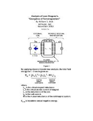
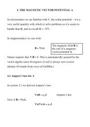
<strong>GB2282708</strong>Page 6 of 19arranged to regulate the operation of the machine by admitting current pulses for a durationdetermined according to the angular position of the rotor, which pulses have a directiontending to oppose the polarization induced in the stator by the rotor polarization as stator androtor poles separate from an in-register position, whereby the action of the rotor magnetizationmeans provides a reluctance motor drive force to bring stator and rotor poles into register andthe action of the stator magnetization windings opposes the counterpart reluctance brakingeffect as the poles separate.According to a feature of this latter aspect of the invention, the electric current sourceconnected to a stator magnetizing winding of a first stator pole comprises, at least partially, theelectrical pulses induced in the stator magnetizing winding of a different second stator pole, thestator pole set configuration in relation to the rotor pole set configuration being such that thefirst stator pole is coming into register with a rotor pole as the second stator pole separatesfrom its in-register position with a rotor pole.BRIEF DESCRIPTION OF THE DRAWINGSFig. 1 presents magnetic core test data showing how the volt-amp reactance power required toset up a constant magnetic flux action in an air gap, as assured by constant a. c. voltageexcitation of a magnetizing winding, falls short of the associated power of the potential implicitin the force action across that air gap.Fig. 2 depicts the test structure to which Fig. I data applies.Fig. 3 depicts the magnetization action at work in causing magnetic 5 flux to traverse an airgapand turn a corner in a circuit through a magnetic core.http://www.geocities.com/theadamsmotor/patent.html6/21/2002
<strong>GB2282708</strong>Page 7 of 19Fig. 4 shows the configuration of a test device used to prove the operating principles of theinvention described.Fig. 5 in its several illustrations depicts the progressive rotor pole to stator pole relationship asa rotor turns through a range of angular positions in a preferred embodiment of a machineaccording to the invention.Fig. 6 shows the form of a disc member which provides location for four permanent magnets inthe machine described.Fig. 7 shows a cross-section of the magnetic circuit structure of a machine embodying theinvention.http://www.geocities.com/theadamsmotor/patent.html6/21/2002
<strong>GB2282708</strong>Page 8 of 19Fig. 8 shows a six stator pole configuration with a seven pole rotor and depicts a schematicseries connected linking of the magnetizing windings of diametrically opposite stator poles.DETAILED DESCRIPTION OF THE INVENTIONThe fact that one can extract energy from the source which powers the intrinsic ferromagneticstate is not explicitly evident from existing textbooks, but it is implicit and, indeed, doesbecome explicit once pointed out, in one textbook authored by F. B. Moullin.His book 'The Principles of Electromagnetism' published by Clarendon Press, Oxford (3rdEdition, 1955) describes on pages 168-174 an experiment concerned with the effect of airgaps between poles in a magnetic circuit. The data obtained are reproduced in Fig. 1, whereProfessor Moullin shows a curve representing a. c. current input for different air gaps, giventhat the voltage supplied is constant. In the same figure, Moullin presents the theoreticalcurrent that would need to be applied to sustain the same voltage, and so the related poleforces across the air gap, assuming (a) no flux leakage and (b) that there is complete equalitybetween inductive energy input and the mechanical energy potential for the magnetization thatis established in the air gap in a quarter-cycle period at the a. c. power excitation frequency.The data show that, even though the level of magnetic polarization is well below the saturationvalue, being confined to a range that is regarded as the linear permeability range intransformer design, there is a clear drop-off of current, and so the volt-amp reactive powerinput needed, as current increases, compared with that predicted by the mechanical potentialhttp://www.geocities.com/theadamsmotor/patent.html6/21/2002
<strong>GB2282708</strong>Page 9 of 19built up in the air gaps.Unless leakage flux is excessive, here was clear evidence of anomalous energy activity.Moullin discusses the leakage flux inferred by this experiment but points out that there isconsiderable mystery in why the effect of a small gap, which should certainly not result in muchflux leakage in the gap region, nevertheless has an enormous effect in causing what has to besubstantial leakage in the light of the energy discrepancy.Moullin did not contemplate that energy had been fed in from the zero-point field system andso he left the issue with the statement that it was virtually impossible to predict leakage flux bycalculation.He was, of course, aware of magnetic domain structure and his argument was that the leakageflux problem was connected with what he termed a 'yawing' action of the flux as it passesaround the magnetic circuit. Normally, provided the level of polarization is below the knee ofthe B-H curve, which occurs at about 70% of saturation in iron cores of general crystalcomposition, it requires very little magnetizing field to change the magnetic flux density. This isassuming that every effort is made to avoid air gaps. The action involves domain wallmovements so that the magnetic states of adjacent domains switch to different crystal axes ofeasy magnetization and this involves very little energy change.However, if there is an air gap ahead in the flux circuit and the magnetizing winding is notsitting on that air gap, the iron core itself has to be the seat of a progressive field source linkingthe winding and the gap. It can only serve in that sense by virtue of the lines of flux in thedomains being forced to rotate somewhat from the preferred easy axes of magnetization, withthe help of the boundary surfaces around the whole core. This action means that, forcibly, andconsequential upon the existence of the air gap, the flux must be carried through the core bythat 'yawing' action. It means that substantial energy is needed to force the establishment ofthose fields within the iron core. More important, however, from the point of view of thisinvention, it means that the intrinsic magnetic polarization effects in adjacent magneticdomains in the iron cease to be mutually parallel or orthogonal so as to stay directed alongaxes of easy magnetization. Then, in effect, the magnetizing action is not just that of themagnetizing winding wrapped around the core but becomes also that of adjacentferromagnetic polarization as the latter act in concert as vacuum-energy powered solenoidsand are deflected into one another to develop the additional forward magnetomotive forces.The consequences of this are that the intrinsic ferromagnetic power source with itsthermodynamic ordering action contributes to doing work in building up forces across the airgap. The task, in technological terms, is then to harness that energy as the gap is closed, asby poles coming together in a reluctance motor, and avoid returning that energy as the polesseparate, this being possible if the controlling source of primary magnetization is well removedfrom the pole gap and the demagnetization occurs when the poles are at the closest position.This energy situation is evident in the Moullin data, because the constant a. c. voltage impliesa constant flux amplitude across the air gap if there is no flux leakage in the gap region. Aconstant flux amplitude implies a constant force between the poles and so the gap width inrelation to this force is a measure of the mechanical energy potential of the air gap. Thereactive volt-amp power assessment over the quarter-cycle period representing thepolarization demand can then be compared with the mechanical energy so made available. Ashttp://www.geocities.com/theadamsmotor/patent.html6/21/2002
<strong>GB2282708</strong>Page 10 of 19already stated, this is how Moullin deduced the theoretical current curve. In fact, as his datashow, he needed less current than the mechanical energy suggested and so he had in hisexperiment evidence of the vacuum energy source that passed unnoticed and is only nowrevealing itself in machines that can serve our energy needs.In the research leading to this patent application the Moullin experiment has been repeated toverify a condition where a single magnetizing winding serves three air gaps. The Moullin testconfiguration is shown in Fig. 2, but in repeating the experiment in the research leading to thisinvention, a search coil was mounted on the bridging member and this was used to comparethe ratio of the voltage applied to the magnetizing winding and that induced in the search coil.The same fall-off feature in current demand was observed, and there was clear evidence ofsubstantial excess energy in the air gap. This was in addition to the inductive energy thatnecessarily had to be locked into the magnetic core to sustain the 'yawing' action of themagnetic flux already mentioned.It is therefore emphasized that, in priming the flux 'yawing' action, energy is stored inductivelyin the magnetic core, even though this has been deemed to be the energy of flux leakageoutside the core. The air gap energy is also induction energy. Both energies are returned tothe source winding when the system is demagnetized, given a fixed air gap. If, however, the airgap closes after or during magnetization, much of that inductive energy goes into themechanical work output. Note then that the energy released as mechanical work is not just thatstored in the air gap but is that stored in sustaining the 'yaw'. Here, then is reason to expect aneven stronger contribution to the dynamic machine performance, one that was not embracedby the calculation of the steady-state situation.Given the above explanation of the energy source, the structural features which are the subjectof this invention will now be described.The 'yawing' action is depicted in Fig. 3, which depicts how magnetic flux navigates a rightangledbend in a magnetic core upon passage through an air gap. By over-simplification it isassumed that the core has a crystal structure that has a preferred axis of magnetization alongthe broken line path. With no air gap, the current needed by a magnetizing winding has only toprovide enough magnetomotive force to overcome the effects of non-magnetic inclusions andimpurities in the core substance and very high magnetic permeabilities can apply. However, assoon as the air gap develops, this core substance has to find a way of setting upmagnetomotive force in regions extending away from the locality of the magnetizing winding. Itcannot do this unless its effect is so powerful that the magnetic flux throughout the magneticcircuit through the core substance is everywhere deflected from alignment with a preferredeasy axis of magnetization. Hence the flux vectors depicted by the arrows move out ofalignment with the broken line shown.There is a 'knock-on' effect progressing all the way around the core from the seat of themagnetizing winding and, as already stated, this harnesses the intrinsic ferromagnetic powerthat, in a system with no air gap, could only be affected by magnetization above the knee ofthe B-H curve. Magnetic flux rotation occurs above that knee, whereas in an ideal core themagnetism develops with very high permeability over a range up to that knee, because itneeds very little power to displace a magnetic domain wall sideways and promote a 90°(Degree) or a 180°(Degree) flux reversal. Indeed, one can have a magnetic permeability of10,000 below the knee and 100 above the knee, the latter reducing progressively until thesubstance saturates magnetically.http://www.geocities.com/theadamsmotor/patent.html6/21/2002
<strong>GB2282708</strong>Page 11 of 19In the situation depicted in Figs 2 or 3 the field strength developed by the magnetizingwindings 1 on magnetic core 2 has to be higher, the greater the air gap, in order to achieve thesame amount of magnetization as measured by the voltage induced in a winding (not shown)on the bridging member 3. However, by virtue of that air gap there is potential for harnessingenergy supplied to that air gap by the intrinsic zero-point field that accounts for the magneticpermeability being over unity and here one can contemplate very substantial excess energypotential, give incorporation in a machine design which departs from convention.One of the applicants has built an operative test machine which is configured as depictedschematically in Fig. 4. The machine has been proved to deliver substantially more mechanicalpower output than is supplied as electrical input, as much as a ratio of 7:1 in one version, anc itcan act regeneratively to produce electrical power.What is shown in Fig. 4 is a simple model designed to demonstrate the principle of operation. Itcomprises a rotor in which four permanent magnets 4 are arrayed to form four poles. Themagnets are bonded into four sectors of a non-magnetic disc 5 using a high densitypolyurethane foam filler and the composite disc is then assembled on a brass spindle6between a split flange coupling. Not shown in the figure is the structure holding the spindlevertically in bearings or the star wheel commutator assembly attached to the upper shaft of thespindle.Note that the magnets present north poles at the perimeter of the rotor disc and that the southpoles are held together by being fimly set in the bonding material.A series of four stator poles were formed using magnetic cores from standard electromagneticrelays are were positioned around the rotor disc as shown. The magnetizing windings 7 onthese cores are shown to be connected in series and powered through commutator contacts 8by a d. c. power supply. Two further stator cores formed by similar electromagnetic relaycomponents are depicted by their windings 9 in the intermediate angle positions shown andthese are connected in series and connected to a rectifier 10 bridged by a capacitor 11.The rotor spindle 6 is coupled with a mechanical drive (not shown) which harnesses the torquedeveloped by the motor thus formed and serves as a means for measuring output mechanicalpower delivered by the machine.In operation, assuming that the rotor poles are held initially off-register with the correspondingstator poles and the hold is then released, the strong magnetic field action of the permanentmagnets will turn the rotor to bring the stator and rotor poles into register. A permanent magnethas a strong attraction for soft iron and so this initial impulse of rotation is powered by thepotential energy of the magnets.Now, with the rotor acting as a flywheel and having inertia it will have a tendency to over-shootthe in-register pole position and that will involve a reverse attraction with the result that therotor will oscillate until damping action brings it to rest. However, if the contacts of thecommutating switch are closed as the poles come first into register, the magnetizing windings7 will receive a current pulse which, assuming the windings are connected in the right sense,tends to demagnetize the four stator cores. This means that, as the stator and rotor polesseparate, the reverse attraction by the magnets is eliminated. Indeed, if the demagnetizingcurrent pulses supplied to the windings 4 are strong enough, the stator poles can reversepolarity and that results in a repulsion giving forward drive to the separating rotor poles.http://www.geocities.com/theadamsmotor/patent.html6/21/2002
<strong>GB2282708</strong>Page 12 of 19The net result of this action is that the rotor will continue rotating until it passes the dead centreangular position which allows the rotor to be attracted in the forward direction by the statorpoles 90°(Degree) forward of those acting originally.The commutating switch 8 needs only to be closed for a limited period of angular travelfollowing the top dead centre in-register position of the stator and rotor poles. The powersupplied through that switch by those pulses will cause the rotor to continue rotating and highspeeds will be achieved as the machine develops its full motor function.Tests on such a machine have shown that more mechanical power can be delivered than issupplied electrically by the source powering the action through the commutating switch. Thereason for this is that, whereas the energy in the air gap between rotor and stator poles whichis tapped mechanically as the poles come into register is provided by the intrinsic power of theferromagnet, a demagnetizing winding on the part of the core system coupled across that airgap needs very little power to eliminate the mechanical force acting across that air gap.Imagine such a winding on the bridging member shown in Fig. 2. The action of current in thatwinding, which sits astride the 'yawing' flux in that bridging member well removed from thesource action of the magnetizing windings 1, is placed to be extremely effective in resisting themagnetizing influence communicated from a distance. Hence very little power is needed toovercome the magnetic coupling transmitted across the air gap.Although the mutual inductance between two spaced-apart magnetizing windings has areciprocal action, regardless of which winding is primary and which is secondary, the action inthe particular machine situation being described involves the 'solenoidal' contributionrepresented by the 'yawing' ferromagnetic flux action. The latter is not reciprocal inasmuch asthe flux 'yaw' depends on the geometry of the system. A magnetizing winding directing fluxdirectly across an air gap has a different influence on the action in the ferromagnetic core fromone directing flux lateral to the air gap and there is no reciprocity in this action.In any event, the facts of experiment do reveal that, owing to a significant discrepancy in suchmutual interaction, more mechanical power is fed into the rotor than is supplied as input fromthe electrical source.This has been further demonstrated by using the two stator windings 9 to respond in agenerator sense to the passage of the rotor poles. An electrical pulse is induced in eachwinding by the passsage of a rotor pole and this is powered by the inertia of the rotor disc 5.By connecting the power so generated to charge the capacitor 11 the d. c. power supply canbe augmented to enhance the efficiency even further. Indeed, the machine is able todemonstrate the excess power delivery from the ferromagnetic system by virtue of electricalpower generation charging a battery at a greater rate than a supply battery is discharged.This invention is concerned with a practical embodiment of the motor-generator principles justdescribed and aims, in its preferred aspect, to provide a robust and reliable machine in whichthe tooth stresses in the rotor poles, which are fluctuating stresses communicating highreluctance drive torque, are not absorbed by a ceramic permanent magnet liable to ruptureowing to its brittle composition.Another object is to provide a structure which can be dismantled and reassembled easily toreplace the permanent magnets, but an even more important object is that of minimizing thestray leakage flux oscillations from the powerful permanent magnets. Their rotation in thehttp://www.geocities.com/theadamsmotor/patent.html6/21/2002
<strong>GB2282708</strong>Page 13 of 19device depicted in Fig. 4 would cause excessive eddy-current induction in nearby metal,including that of the machine itself, and such effects are minimized if the flux changes areconfined to paths through steel laminations and if the source flux from the magnets has asymmetry or near symmetry about the axis of rotation.Thus, the ideal design with this in mind is one where the permanent magnet is a hollowcylinder located on a non-magnetic rotor shaft, but, though that structure is within the scope ofthis invention, the machine described will utilize several separate permanent magnetsapproximating, in function, such a cylindrical configuration.Referring to Fig. 4, it will further be noted that the magnetic flux emerging from the north poleswill have to find its way along leakage paths through air to re-enter the south poles. Forperiods in each cycle of machine operation the flux will be attracted through the stator cores,but the passage through air is essential and so the power of the magnets is not used to fulladvantage and there are those unwanted eddy-current effects.To overcome this problem the invention provides for two separate rotor sections and the statorpoles become bridging members, which with optimum design, allow the flux from the magnetsto find a route around a magnetic circuit with minimal leakage through air as the flux is directedthrough one or other pairs of air gaps where the torque action is developed.Reference is now made to Fig. 5 and the sequence of rotor positions shown. Note that thestator pole width can be significantly smaller that that of the rotor poles. Indeed, for operationusing the principles of this invention, it is advantageous for the stator to have a much smallerpole width so as to concentrate the effective pole region. A stator pole width of half that of therotor is appropriate but it may be even smaller and this has the secondary advantage ofrequiring smaller magnetizing windings and so saving on the loss associated with the currentcircuit.The stator has eight pole pieces formed as bridging members 12, more clearly represented inFig. 7, which shows a sectional side view through two rotor sections 13 axially spaced on arotor shaft 14. There are four permanent magnets 15 positioned between these rotor sectionsand located in apertures 16 in a disc 17 of a non-magnetic substance of high tensile strength,the latter being shown in Fig. 6. The rotor sections are formed from disc laminations ofelectrical steel which has seven large teeth, the salient poles. Magnetizing windings 18mounted on the bridging members 12 constitute the system governing the action of the motorgeneratorbeing described.The control circuitry is not described as design of such circuitry involves ordinary skillpossessed by those involved in the electricalengineering art.It suffices, therefore, to describe the merits of the structural design configuration of the coreelements of the machine. These concern principally the magnetic action and, as can beimagined from Fig. 7, the magnetic flux from the magnets enters the rotor laminations bytraversing the planar faces of the laminations and being deflected into the plane of thelaminations to pass through one or other of the stator pole bridging members, returning by asimilar route through the other rotor.By using eight stator poles and seven rotor poles, the latter having a pole width equal to halfthe pole pitch in an angular sense, it will be seen from Fig. 5, that there is always a fluxhttp://www.geocities.com/theadamsmotor/patent.html6/21/2002
<strong>GB2282708</strong>Page 14 of 19passage across the small air gap between stator and rotor poles. However, as one polecombination is in-register the diametrically-opposed pole combinations are out-of-register.As described by reference to Fig. 4 the operation of the machine involves allowing the magnetto pull stator and rotor poles into register and then, as they separate, pulsing the winding onthe relevant stator member to demagnetize that member. In the Fig. 4 system, all the statormagnetizing windings were pulsed together, which is not an optimum way in which to drive amulti-pole machine.In the machine having the pole structure with one less rotor pole than stator poles (or anequivalent design in which there is one less stator pole than rotor poles) this pulsing action canbe distributed in its demand on the power supply, and though this makes the commutationswitch cicuit more expensive the resulting benefit outweighs that cost.However, there is a feature of this invention by which that problem 15 can be alleviated if noteliminated.Suppose that the rotor has the position shown in Fig. 5(a) with the rotor pole denoted R 1midway between stator poles S 1and S 2imagine that this is attracted towards the in-registerposition with stator pole S 2. Upon reaching that in-register position, as shown in Fig. 5 (c),suppose that the magnetizing winding of stator pole S 2is excited by a current pulse which issustained until the rotor reaches the Fig. 5(e) position. The combination of these two actionswill have imparted a forward drive impulse powered by the permanent magnet in the rotorstructure and the current pulse which suppresses braking action will have drawn a smalleramount of energy from the electrical power source that supplies it. This is the same process aswas described by reference to Fig. 4.However, now consider the events occurring in the rotor action diametrically opposite that justdescribed. In the Fig 5(a) position rotor pole R 4has come fully into register with stator pole S 5and so stator pole S 5is ready to be demagnetized. However, the magnetic coupling betweenthe rotor and stator poles is then at its strongest. Note, however, that in that Fig. 5(a) positionR 5is beginning its separation from stator pole S 6and the magnetizing winding of stator pole S 6must then begin draw power to initiate demagnetization. During that following period of poleseparation the power from the magnet is pulling R 1and S 2together with much more actionthan is needed to generate that current pulse needed to demagnetize S 6. It follows, therefore,that, based on the research findings of the regenerative excitation in the test system of Fig. 4,the series connection of the magnetizing windings on stators S 2and S 6will, without needingany commutative switching, provide the regenerative power needed for machine operation.The complementary action of the two magnetizing windings during the pole closure and poleseparation allows the construction of a machine which, given that the zero-point vacuumenergy powering the ferromagnet is feeding input power, will run on that source of energy andthereby cool the sustaining field system.There are various design options in implementing what has just been proposed. Muchdepends upon the intended use of the machine. If it is intended to deliver mechanical poweroutput the regenerative electrical power action can all be used to power the demagnetizationhttp://www.geocities.com/theadamsmotor/patent.html6/21/2002
<strong>GB2282708</strong>Page 15 of 19with any surplus contributing to a stronger drive torque by reversing the polarity of the statorpoles during pole separation.If the object is to generate electricity by operating in generator mode then one could design amachine having additional windings on the stator for delivering electrical power output.However, it seems preferable to regard the machine as a motor and maximize its efficiency inthat capacity whilst using a mechanical coupling to an alternator of conventional design for theelectrical power generation function. In the latter case it would still seem preferable to use theself-excitation feature already described to reduce commutation switching problems.The question of providing for machine start-up can be addressed by using a separate startermotor powered from an external supply or by providing for current pulsing limited to, say, twostator poles. Thus, for example, with the eight stator pole configuration, the cross-connectedmagnetizing windings could be limited to three stator pairs, with two stator magnetizingwindings left free for connection to a pulsed external supply source.If the latter feature were not required, then the stator magnetizing windings would all beconnected in pairs on a truly diametrically opposite basis. Thus Fig. 8 shows a rotor-statorconfiguration having six stator poles interacting with seven rotor poles and stator magnetizingwindings linked together in pairs.The invention, therefore, offers a wide range of implementation possibilities, which, in the lightof this disclosure will become obvious to persons skilled in the electrical engineering art, allbased, however, on the essential but simple principle that a rotor has a set of poles of commonpolarity which are attracted into register with a set of stator poles that are suppressed orreversed in polarity magnetically during pole separation. The invention, however, also offersthe important feature of minimizing commutation and providing further for a magnetic fluxclosure that minimizes the leakage flux and fluctuations of leakage flux and so contributes toefficiency and high torque performance as well as durability and reliability of a machineincorporating the invention.It is noted that although a machine has been described which uses two rotor sections it ispossible to build a composite version of the machine having several rotor sections. In theeventuality that the invention finds use in very large motor-generator machines the problem ofproviding very large magnets can be overcome by a design in which numerous small magnetsare assembled. The structural concept described by reference to Fig. 6 in providing locatingapertures to house the magnets makes this proposal highly feasible. Furthermore, it is possibleto replace the magnets by a steel cylinder and provide a solenoid as part of the stator structureand located between the rotor sections. This would set up an axial magnetic field magnetizingthe steel cylinder and so polarizing the rotor. However, the power supplied to that solenoidwould detract from the power generated and so such a machine would not be as effective asthe use of permanent magnets such as are now available. Nevertheless, should one seesignificant progress in the development of warm superconductor materials, it may becomefeasible to harness the self-generating motor-generator features of the invention, with itsselfcooling properties, by operating the device in an enclosure at low temperatures andreplacing the magnets by a superconductive statorsupported solenoid.CLAIMShttp://www.geocities.com/theadamsmotor/patent.html6/21/2002
<strong>GB2282708</strong>Page 16 of 191. An electrodynamic motor-generator machine comprising a stator configured to provide a setof stator poles, a corresponding set of magnetizing windings mounted on the stator pole set, arotor having two sections each of which has a set of salient pole pieces, the rotor sectionsbeing axially spaced along the axis of rotation of the rotor, rotor magnetization means disposedbetween the two rotor sections arranged to produce a unidirectional magnetic field whichmagnetically polarizes the rotor poles, whereby the pole faces of one rotor section all have anorth polarity and the pole faces of the other rotor section all have a south polarity and electriccircuit connections between an electric current source and the stator magnetizing windingsarranged to regulate the operation of the machine by admitting current pulses for a durationdetermined according to the angular position of the rotor, which pulses have a directiontending to oppose the polarization induced in the stator by the rotor polarization as stator androtor poles separate from an in-register position, whereby the action of the rotor magnetizationmeans provides a reluctance motor drive force to bring stator and rotor poles into register andthe action of the stator magnetization windings opposes the counterpart reluctance brakingeffect as the poles separate.2. A motor-generator according to claim 1, wherein the circuit connecting the electric currentsource and the stator magnetizing windings is designed to deliver current pulses which are ofsufficient strength and duration to provide demagnetization of the stator poles as the stator androtor poles separate from an in-register position.3. A motor-generator according to claim 1, wherein the circuit connecting the electric currentsource and the stator magnetizing windings is designed to deliver current pulses which are ofsufficient strength and duration to provide a reversal of magnetic flux direction in the statorpoles as the stator and rotor poles separate from an in-register position, whereby to draw onpower supplied from the electric current source to provide additional forward drive torque.4. A motor-generator according to claim 1, wherein the electric current source connected to astator magnetizing winding of a first stator pole comprises, at least partially, the electricalpulses induced in the stator magnetizing winding of a different second stator pole, the statorpole set configuration in relation to the rotor pole set configuration being such that the firststator pole is coming into register with a rotor pole as the second stator pole separates from itsin-register position with a rotor pole.5. A motor-generator according to claim 1, wherein the number of poles in a set of stator polesis different from the number of rotor poles in each rotor section.6. A motor-generator according to claim I, wherein the stator configuration provides polepieces which are common to both rotor sections in the sense that when stator and rotor polesare in-register the stator pole pieces constitute bridging members for magnetic flux closure in amagnetic circuit including that of the rotor magnetization means disposed between the tworotor sections.7. A motor-generator according to claim 6, wherein the number of poles in a set of stator polesand the number of rotor poles in each section do not share a common integer factor and thenumber of rotor poles in one rotor section is the same as that in the other rotor section.8. A motor-generator according to claim 7, wherein the number of poles in a stator set and thenumber of poles in a rotor section differs by one and the pole faces are of sufficient angularwidth to assure that the magnetic flux produced by the rotor magnetization means can find ahttp://www.geocities.com/theadamsmotor/patent.html6/21/2002
<strong>GB2282708</strong>Page 17 of 19circuital magnetic flux closure route through the bridging path of a stator pole and throughcorresponding rotor poles for any angular position of the rotor.9. A motor-generator according to claim 8, wherein each rotor section comprises seven poles.10. A motor-generator according to claim 7, wherein there are N rotor poles in each rotorsection and each has an angular width that is 180/N degree of angle.11. A motor-generator according to claim 7, wherein the stator pole faces have an angularwidth that is no greater than half the angular width of a rotor pole.12. A motor-generator according to claim 1, wherein the rotor sections comprise circular steellaminations in which the rotor poles are formed as large teeth at the perimeter, and the rotormagnetization means comprise a magnetic core structure the end faces of which abut twoassemblies of 20 such laminations forming the two rotor sections.13. A motor-generator according to claim 1 in which the rotor magnetization means comprisesat least one permanent magnet located with its polarization axis parallel with the rotor axis.14. A motor-generator according to claim 13, wherein an apertured metal disc that is of a nonmagnetizablesubstance is mounted on a rotor shaft and positioned intermediate the two rotorsections and each aperture provides location for a permanent magnet, whereby the centrifugalforces acting on the permanent magnet as the rotor rotates are absorbed by the stresses setup in the disc.15. A motor-generator according to claim 1, having a rotor mounted on a shaft that is of a nonmagnetizablesubstance, whereby to minimize 5 magnetic leakage from the rotor magnetizingmeans.16. An electrodynamic motor-generator machine comprising a stator configured to provide aset of stator poles, a corresponding set of magnetizing windings mounted on the stator poleset, a rotor having two sections each of which has a set of salient pole pieces, the rotorsections being axially spaced along the axis of rotation of the rotor, rotor magnetization meansincorporated in the rotor structure and arranged to polarize the rotor poles, whereby the polefaces of one rotor section all have a north polarity and the pole faces of the other rotor sectionall have a south polarity and electric circuit connections between an electric current source andthe stator magnetizing windings arranged to regulate the operation of the machine by admittingcurrent pulses for a duration determined according to the angular position of the rotor, whichpulses have a direction tending to oppose the polarization induced in the stator by the rotorpolarization as stator and rotor poles separate from an in-register position, whereby the actionof the rotor magnetization means provides a reluctance motor drive force to bring stator androtor poles into register and the action of the stator magnetization windings opposes thecounterpart reluctance braking effect as the poles separate.17. A motor- generator according to claim 16, wherein the electric current source connected toa stator magnetizing winding of a first stator pole comprises, at least partially, the electricalpulses induced in the stator magnetizing winding of a different second stator pole, the statorpole set configuration in relation to the rotor pole set configuration being such that the firststator pole is coming into register with a rotor pole as the second stator pole separates from itsin-register position with a rotor pole.http://www.geocities.com/theadamsmotor/patent.html6/21/2002
<strong>GB2282708</strong>Page 18 of 19AMENDMENTS TO THE CLAIMS HAVE BEEN FILED AS FOLLOWS1. An electrodynamic motor-generator machine comprising a stator configured to provide a setof stator poles, a corresponding set of magnetizing windings mounted on the stator pole set, arotor having two sections each of which has a set of salient pole pieces, the rotor sectionsbeing axially spaced along the axis of rotation of the rotor, rotor magnetization means disposedbetween the two rotor sections arranged to produce a unidirectional magnetic field whichmagnetically polarizes the rotor poles, whereby the pole faces of one rotor section all have anorth polarity and the pole faces of the other rotor section all have a south polarity and electriccircuit connections between an electric current source and the stator magnetizing windingsarranged to regulate the operation of the machine by admitting current pulses for a durationdetermined according to the angular position of the rotor, which pulses have a directiontending to oppose the polarization induced in the stator by the rotor polarization as stator androtor poles separate from an in-register position, whereby the action of the rotor magnetizationmeans provides a reluctance motor drive force to bring stator and rotor poles into register andthe action of the stator magnetization windings opposes the counterpart reluctance brakingeffect as the poles separate, the machine being characterized in that the stator comprisesseparate ferromagnetic bridging members mounted parallel with the rotor axis, the ends ofwhich constitute stator poles and the core sect ions of which provide cross-section disposedantiparallel with the unidirectional magnetic field polarization axis of the rotor magnetizingmeans.2. A motor-generator according to claim 1, wherein the circuit connecting the electric currentsource and the stator magnetizing windinga is designed to deliver current pulses which are ofsufficient strength and duration to provide demagnetization of the stator poles as the stator androtor poles separate from an in-register position.3. A motor-generator according to claim 1, wherein the circuit connecting the electric currentsource and the stator magnetizing windings is designed to deliver current pulses which are ofsufficient strength and duration to provide a reversal of magnetic flux direction in the statorpoles as the stator and rotor poles separate from an in- register position, whereby to draw onpower supplied from the electric current source to provide additional forward drive torque.4. A motor-generator according to claim 1, wherein the electric current source connected to astator magnetizing winding of a first stator pole comprises, at least partially, the electricalpulses induced in the stator magnetizing winding of a different second etator pole, the statorpole set configuration in relation to the rotor pole set configuration being such that the firststator pole is coming into register with a rotor pole as the second stator pole separates from itsin-register position with a rotor pole.5. A motor-generator according to claim 1, wherein the number of poles in a set of atator polesis different from the number of rotor poles in each rotor section.6. A motor-generator according to claim 1, wherein the stator configuration provides polepieces which are common to both rotor sections in the sense that when stator and rotor polesare in-register the stator pole pieces constitute bridging members for magnetic flux closure in amagnetic circuit including that of the rotor magnetization means disposed between the tworotor sections.http://www.geocities.com/theadamsmotor/patent.html6/21/2002
<strong>GB2282708</strong>Page 19 of 197. A motor-generator according to claim 6, wherein the number of poles in a set of stator polesand the number of rotor poles in each section do not share a common integer factor and thenumber of rotor poles in one rotor section is the same as that in the other rotor section.Search Examiner:J. COCKITTCategories of documentsX: Document indicating lack of novelty or of inventive step.A: Document indicating technological background and/or state of the art.CategoryIdentity of document and relevant passagesRelevant toclaim(s)XGB 0547668A(HITCHCOCK) see page 6 lines 54 to 71; Figures6, 71-3, 6,12-14, 16 atleastXUS 4972112A(KIM) see whole document1-3 at leastAUS 4873463A(JONES)http://www.geocities.com/theadamsmotor/patent.html6/21/2002