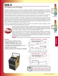
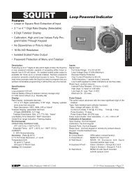
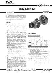
REPAIR cont’d.Figure 17NOTE: In order to preserve the UL Listing or CSA Certificationfor pump safety, return the entire pump to the factory formotor repair or replacement. For products serviced outsidethe factory, the UL and CSA nameplates must bedefaced to indicate the equipment may no longer meetthe requirements for UL Listing or CSA Certification. Thisdoes not apply to products serviced outside the factoryunder the UL program for Rebuilt Motors for Use inHazardous Locations and the CSA rebuild program.3. Remove switch bracket mounting screw and gentlypull switch from switch cavity. (Figure 18)Figure 18Replace Motor Shaft Seal1. Turn the pump OFF and disconnect from power.2. Remove the gear coverplate, gears, and drive key asdescribed in Gear Replacement instructions.3. Remove the motor from the pump housing.4. Remove the motor shaft seal by prying out with a smallscrewdriver. (Figure 19)Figure 19NOTE: Switch shown is for models M-<strong>150S</strong> and M-180S.Model M-240S switch does not require a jumper wireand circuit breaker.4. Remove the red wires from the terminals on the backof the switch.5. Remove the remaining wire on motor protector thenremove the motor protector from switch cavity.6. Install new motor protector by reversing above procedure.NOTE: Make sure the O-ring is seated properly beforetightening the switch coverplate.Replace Switch Lever orSwitch Lever Shaft O-Ring1. Turn off the pump and disconnect from power.2. Remove the switch coverplate from the pump housing.3. Remove the screw connecting the switch cam to thecoverplate.4. Remove the cam and switch lever.5. Replace the switch lever or switch lever shaft O-ring asneeded.6. Reassemble by reversing the above procedure. Make surethe O-ring is seated properly before tightening the coverplate.Back of <strong>Pump</strong>5. Lubricate the gear shaft with WD-40 or a similar penetratingoil.6. Press a new motor shaft seal evenly in the pump housinguntil seated. Lubricate the seal with a lightweightmotor oil.7. Gently slide the shaft through the seal until the motor isflush against the pump housing.8. Tighten the motor to the pump housing. Check for properinstallation by working a .0015 feeler gauge around themotor flange. The gauge should not fit between theflange and the housing.9. Install the gears and drive key as described in GearReplacement instructions.8
TROUBLESHOOTINGSYMPTOM PROBABLE CAUSE CORRECTIVE ACTIONA. MOTOR DOES NOT 1. Fuse blown Inspect fuse in fuse holder on power cord for Model M-240S. If blown, replaceRUNusing instructions in the Repair Section.2. Switch defective Remove switch coverplate and inspect switch. Replace, if necessary.3. Motor burned out Replace motor as described in the Repair Section.4. Switch or electrical connections faulty Inspect for damaged motor protector, defective wiring or switch, or improper(Model M-<strong>150S</strong> and Model M-180S) electrical connections. Replace as needed and re-install.5. Circuit breaker tripped Turn power off at source. Inspect the pump thoroughly; clean or repair. Resetcircuit breaker by turning the power switch off then back on.B. MOTOR RUNS BUT 1. Suction pipe clogged, damaged, or missing Remove pump from tank. Inspect suction pipe. Clean or replace, as necessary.DOES NOT PUMP2. Gear coverplate or O-ring damaged Remove and inspect the coverplate and O-ring. Replace, as necessary. Referto the Repair Section on Servicing O-rings.3. Strainer clogged or defective Remove strainer coverplate. Remove and clean strainer. Install again.4. Bypass poppet O-ring worn or missing Inspect O-ring using instructions in the Repair Section. Replace, if necessary.5. Bypass poppet O-ring dirty Remove poppet assembly and clean poppet and cavity.6. Bypass poppet binding or damaged Using instructions in the Repair Section, remove the bypass poppet, spring,and O-ring. Clean cavity. Inspect and replace components, as necessary.7. System air leak Tighten all pump fittings and connections. Inspect suction pipe for leaks ordamage.8. System air lock This can occur if external filter, meters, or an off-the-shelf automatic nozzle isused. To correct, remove the pipe plug in the top outlet port and fill the gearcavity with fuel. Use of a factory-supplied automatic nozzle is recommended.9. Poor connections or low voltage Make sure electrical connections are secure. Also check battery voltage.10. <strong>Fuel</strong> level low Fill tank.11. Motor running backwards due to Connect red wire to positive (+). Gear with key should turn counterclockwise.incorrect polarityC. LOW FLOW RATE 1. Poor connections or low voltage Make sure electrical connections are secure. Also check battery voltage2. Strainer partially clogged Remove the strainer coverplate. Remove and clean the strainer. Install again.3. Suction pipe clogged or damaged Remove pump from tank. Inspect suction pipe. Clean or replace, as necessary.4. <strong>Fuel</strong> tank empty Fill tank.5. Using off-the-shelf automatic nozzle Factory-supplied automatic nozzle is recommended.6. System air leak Tighten all pump fittings and connections. Inspect suction pipe for leaks ordamage. Replace, as necessary.7. Suction pipe too close to tank bottom Suction pipe must have at least 1/4 in. (0.6 cm) clearance from the tank bottom.8. Bypass poppet spring weak Using instructions in the Repair Section, remove the bypass poppet andinspect spring. Replace, if necessary.D. MOTOR STALLS 1. Motor protector activated Turn off switch. Allow motor to cool, then turn on switch.WHEN OPERATING2. Gears locked Remove gear coverplate and inspect gears and drive key. Make sure gearsIN BYPASS MODEturn freely with the key removed. Replace, if worn.3. Wiring defective Use Wiring instructions in the Installation Section to ensure proper connections.4. Bypass poppet binding or damaged Using instructions in the Repair Section, remove the bypass poppet, spring,and O-ring. Clean cavity. Inspect components and replace, as necessary.5. Motor defective Replace motor as described in the Repair Section.E. SWITCH FAILS TO 1. Switch or electrical connections faulty Inspect for a blown fuse, defective wiring or switch, or improper electricalOPERATE MOTOR (Model M-240S) connections. Replace or install again, as necessary. Refer to Switch Replacementinstructions in the Repair Section.2. Motor burned out Replace motor as described in the Repair Section.3. Motor protector activated Turn off switch. Allow motor to cool, then turn on switch.4. Switch or electrical connections faulty Inspect for damaged motor protector, defective wiring or switch, or(Models M-<strong>150S</strong> and M-180S)improper electrical connections. Replace as needed and re-install.F. RAPID OVERHEATING 1. Duty cycle too long <strong>Pump</strong> operation should not exceed the standard duty cycle of 30 minutes ON,OF MOTORand 30 minutes OFF. Allow the pump to cool for 30 minutes.2. Strainer clogged Remove strainer coverplate. Remove and clean strainer. Install again.3. Suction pipe clogged or damaged Remove pump from tank. Inspect suction pipe. Clean or replace, as necessary.4. Gears worn Remove gear coverplate and inspect gears and drive key. Make sure gearsturn freely with key removed. Replace, if necessary.5. <strong>Fuel</strong> level low Fill tank.6. Running too long in bypass mode Limit bypass operation to 10 minutes.9