GPI M-150S Fuel Transfer Pump Manual PDF - Instrumart
GPI M-150S Fuel Transfer Pump Manual PDF - Instrumart
GPI M-150S Fuel Transfer Pump Manual PDF - Instrumart

You also want an ePaper? Increase the reach of your titles
YUMPU automatically turns print PDFs into web optimized ePapers that Google loves.
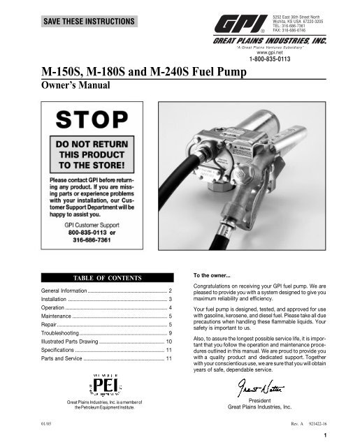
SAVE THESE INSTRUCTIONS5252 East 36th Street NorthWichita, KS USA 67220-3205TEL: 316-686-7361FAX: 316-686-6746M-<strong>150S</strong>, M-180S and M-240S <strong>Fuel</strong> <strong>Pump</strong>Owner’s <strong>Manual</strong>“A Great Plains Ventures Subsidiary”www.gpi.net1-800-835-0113TABLE OF CONTENTSGeneral Information ........................................................ 2Installation ...................................................................... 3Operation ........................................................................ 4Maintenance ................................................................... 5Repair.............................................................................. 5Troubleshooting.............................................................. 9Illustrated Parts Drawing .............................................. 10Specifications ............................................................... 11Parts and Service ......................................................... 11To the owner...Congratulations on receiving your <strong>GPI</strong> fuel pump. We arepleased to provide you with a system designed to give youmaximum reliability and efficiency.Your fuel pump is designed, tested, and approved for usewith gasoline, kerosene, and diesel fuel. Please take all dueprecautions when handling these flammable liquids. Yoursafety is important to us.Also, to assure the longest possible service life, it is importantthat you follow the operation and maintenance proceduresoutlined in this manual. We are proud to provide youwith a quality product and dedicated support. Togetherwith your conscientious use, we are sure that you will obtainyears of safe, dependable service.Great Plains Industries, Inc. is a member ofthe Petroleum Equipment Institute.PresidentGreat Plains Industries, Inc.01/05Rev. A 921422-161
GENERAL INFORMATIONThe information in this manual applies to a series of <strong>GPI</strong> pumps:• M-<strong>150S</strong> 12-volt, available with automatic or manualnozzle• M-180S High flow pump available with automatic ormanual nozzle• M-240S 24-volt pump with manual nozzleThe information applies to all models, except where noted.This manual will assist you in operating and maintaining your12-volt or 24-volt fuel pump. It furnishes information whichwill help you achieve years of dependable performance andtrouble-free operation.Please take a few moments to read through this manualbefore installing and operating your pump. If you have problemswith the pump, refer to the Maintenance and TroubleshootingSections.If you need assistance, contact the dealer from whom youreceived your pump. If you need further assistance, pleasecall the factory.How to Use this <strong>Manual</strong>Most information in this manual applies to both 12-volt and 24-volt electric gear pumps with an automatic or manual nozzle.This symbol is used throughout this manualto call your attention to safety messages.Warnings alert you to the potential for personal injury.Cautions call attention to practices or procedures which maycause damage to your equipment.Notes give you information that can improve efficiency ofoperations.It is your responsibility to:• know and follow applicable national, state, and local safetycodes pertaining to installing and operating electricalequipment for use with flammable liquids.• know and follow all safety precautions when handlingpetroleum fuels.• insure that all equipment operators have access to adequateinstructions concerning safe operating and maintenanceprocedures.Safety InstructionsThis is a safe product, designed and manufactured to meetthe high safety standards of Underwriters Laboratories (Motorfor Hazardous Locations) and the Canadian StandardsAssociation (CSA). It is designed to safely handle fuel productsand, if installed, operated, and maintained correctly, willgive years of dependable service.Important InformationTo insure safe operation, all fuel transfer systems must beproperly grounded.Proper grounding means a continuous metal-to-metal contactfrom one component to the next, including tank, bung,pump, meter, filter, hose, and nozzle. Care should be takento insure proper grounding during initial installation and afterany service or repair procedures.All factory-supplied accessories and components assureproper grounding.Here is a list of major warnings and cautions that are giventhroughout this manual. Please take a moment to review themnow for your future safety.1. To prevent physical injury, observe precautions againstfire or explosion when dispensing fuel. Do not operate thesystem in the presence of any source of ignition includingrunning or hot engines, lighted cigarettes, or gas or electricheaters.2. Observe precautions against electrical shock when operatingthe system. Serious or fatal shock can result fromoperating electrical equipment in damp or wet locations.3. Avoid prolonged skin contact with petroleum fuels. Useprotective goggles, gloves, and aprons in case of splashingor spills. Change saturated clothing and wash skinpromptly with soap and water.4. This pump is designed for use only with gasoline, kerosene,and diesel fuel. Do not use this pump for dispensingany fluids other than those for which it was designed. Todo so may damage pump components and will void thewarranty.5. Do not leave the system running without fluids. “Dryrunning” can damage the pump. If the system fails todeliver fuel after 15 to 20 seconds, turn the system off andrefer to the Troubleshooting Section.6. Inspect external pump wiring regularly to make sure it iscorrectly attached to the battery. To avoid electrical shock,use extra care when connecting the pump to power.7. Do not pump the tank completely dry, as contaminantsfrom the bottom of the tank may enter the pump.8. To avoid pump damage, do not run the pump for morethan 10 minutes with the nozzle closed.9. The duty cycle of this pump is 30 minutes ON and 30minutes OFF. Allow the pump to cool for 30 minutes.10. Observe precautions against electrical shock when servicingthe pump. Always disconnect power before repairingor servicing. Never apply electrical power to thesystem when any of the coverplates are removed.11. If using solvent to clean pump components or tank, observethe solvent manufacturer’s recommendations forsafe use and disposal.Damage InspectionUpon receipt of your system, inspect all parts and components.Remove protective caps and plugs, as needed, for athorough inspection.If any items are damaged or missing, please contact yourdealer or distributor.2
INSTALLATIONBefore installation, wrap all threaded fuel connections withthree to four turns of Teflon ® tape or a pipe thread sealantapproved for use with petroleum fuels.Review the Important Information on page 1 before proceeding.PrimingThis pump is designed to self-prime with dry gears. Expectsuction lift as follows:<strong>Manual</strong> Nozzle: 5.5 feet (1.7 m) with diesel6.7 feet (2.1 m) with gasolineAutomatic Nozzle: 4.8 feet (1.5 m) with diesel5.8 feet (1.8 m) with gasolineIf your installation requires a greater distance from the lowestfuel level to the pump, the pump may not prime until the gearsare coated with fluid.To coat the gears, remove the plug on the top of the pump (asdetailed in Figure 8) and pour a small quantity of motor oil intothe gear cavity. Replace the plug, turn the pump on, and openthe nozzle.A UL Listed foot valve with pressure relief will be required tomaintain prime.Install Bung Adapter and Suction PipeBefore installation, wrap all threaded fuel connections withthree to four turns of Teflon ® tape or a pipe thread sealantapproved for use with petroleum fuels.1. Tighten the bung adapter snugly on the fuel tank.2. Place the union ring gasket into the inlet fitting on thebottom of the pump.3. Thread the suction pipe into the inlet fitting and tightenuntil snug.Install <strong>Pump</strong> on Tank1. Clean the tank interior of all dirt and foreign material.2. Extend the suction pipe to its full length and insert into thetank opening. (Figure 1)3. Place the pump on the bung adapter and tighten theunion ring securely with a pipe wrench. Make sure theunion ring is not cross-threaded.NOTE: To prevent pressure buildup and possible fuel leaksthrough the nozzle, make sure the tank is vented. A ventcap rated at 3 psi or less is recommended.Install Electrical Connections<strong>Pump</strong>s designed for a 12-volt power source should be connectedto a 12-volt battery. <strong>Pump</strong>s designed for a 24-voltpower source should be connected to a 24-volt battery. Donot attempt to install on a 115-volt power source.To install power cord:1. Remove the electrical coverplate from the pump housing.(Figure 2)Figure 22. Models M-<strong>150S</strong> and M-180S: Adjust power cord todesired length. Strip 3 to 4 inches (7.5 to 10 cm) ofouter insulation from the power cord.Model M-240S only: Adjust power cord to desiredlength. Strip 3 to 4 inches (7.5 to 10 cm) of outerinsulation from the power cord end without the fuse.3. Slide the strain relief grip over the end of the power cord.The threaded end of the strain relief grip must face thepower cord end. (Figure 3)Figure 3Figure 14. Strip 1/2 inch (1.3 cm) of insulation from the red and blackpower cord wires.The suction pipe will adjust to the length needed to reston the tank bottom.5. Insert the power cord through the power cord inlet on theback of the pump. (Figure 4) Using wire nuts, connect theblack wire of the power cord to the black wire in theelectrical cavity. Connect the red wires in the samemanner.6. Position wires inside the electrical cavity until flush. Insertthe strain relief into the back of pump and tighten. Tightenthe strain relief grip securely.3
INSTALLATION cont’d.Figure 4CAUTION: Do not leave the system running without fluids.“Dry running” can damage the pump. If the pump fails todeliver fuel after 15 to 20 seconds, turn OFF and refer tothe Troubleshooting Section.7. Make sure mating surfaces are clean. Install the electricalcoverplate and tighten screws securely.The system is now wired for negative ground. To connect topower source, red is positive (+).Install Hose and NozzleNOTE: If installing accessories such as flow meters or filters,do so now, following the manufacturer’s instructions.1. Tighten the hose into the pump outlet.2. Tighten the nozzle onto the opposite hose end.3. Place the nozzle into the nozzle holder on the pumphousing. Note that the nozzle cannot be placed in theholder unless the pump is OFF.NOTE: The nozzle holder allows the pump to be locked whenthe nozzle is in place.OPERATION!To prevent physical injury, observe precautions against fire orexplosion when dispensing fuel. Do not operate the systemin the presence of any source of ignition including running orhot engines, lighted cigarettes, or gas or electric heaters.!Observe precautions against electrical shock when operatingthe system. Serious or fatal shock can result from operatingelectrical equipment in damp or wet locations.!!!! W A R N I N G !!!!!! W A R N I N G !!!!!! W A R N I N G !!!Avoid prolonged skin contact with petroleum fuels. Use protectivegoggles, gloves, and aprons in case of splashing orspills. Change saturated clothing and wash skin promptly withsoap and water.CAUTION: This pump is designed for use only with gasoline,kerosene, and diesel fuel. Do not use this pump fordispensing any fluids other than those for which it wasdesigned. To do so may damage pump components andwill void the warranty.Before Each Use1. Check for leaks around seals or connections. Refer to theTroubleshooting Section of this manual for correctiveaction.2. Make sure hoses are in good condition and connectionsare tight.3. Make sure the work area is dry.4. Inspect wiring to ensure the pump is properly grounded.Also check for any corroded or damaged wiring.!!!! W A R N I N G !!!Inspect external pump wiring regularly to ensure it is correctlyattached to the battery. To avoid electrical shock, use extracare when connecting the pump to power.5. Ensure the tank contains enough fuel.CAUTION: Do not pump the tank completely dry, as contaminantsfrom the bottom of the tank may enter the pump.6. Check for obvious signs of fuel contamination such as aloose or missing tank lid which could allow debris intothe tank.Dispense <strong>Fuel</strong>1. To turn the pump ON, remove the nozzle from its holderand push the switch lever up.NOTE: The nozzle holder and switch are designed so thepump motor cannot operate with the nozzle in the holder.2. Insert the nozzle into the receiving tank or container.Squeeze the handle to start fuel flow.This pump is designed to self-prime. If it does not begin todeliver fuel within 15 to 20 seconds after turning the pump ONand opening the nozzle, turn OFF. Refer to the Priming andTroubleshooting Sections to correct problem.An automatic bypass valve prevents pressure buildup whenthe pump is ON with the nozzle closed.CAUTION: To avoid pump damage, do not run the pump formore than ten minutes with the nozzle closed.Do not overfill the tank. Repeated attempts to “top off” thetank with an automatic nozzle may result in overfilling.3. After dispensing fuel, release the nozzle handle, turn thepump OFF, and return the nozzle to its holder.CAUTION: The duty cycle of this pump is 30 minutes ON and30 minutes OFF. Allow to cool for 30 minutes.Motor Protector (Models M-<strong>150S</strong> and M-180S only)The motor protector trips automatically. This feature providesadded protection against motor damage and must be resetmanually.4
When the motor protector trips, reset by turning the switch toOFF. Let the pump cool then turn ON again. If the motor protectortrips again, see the Troubleshooting Section of this manual.Motor Protector (M-240S model)An inline fuse provides Overload Protection on the 24-voltmodels. Follow the instructions in the Repair Section toreplace the fuse.MAINTENANCEThis pump is designed for minimum maintenance. Motorbearings are sealed and require no lubrication. Inspect thepump and components regularly for fuel leaks and make surethe hose and power cord are in good condition. Keep thepump exterior clean to help identify leaks.Perform a regular visual inspection of the system using the“Before Each Use” procedure in the Operation Section.Do not use this pump to pump water, chemicals, or herbicides.Dispensing any fluid other than gasoline, diesel, orkerosene fuel will damage the pump. Use of the pump withunauthorized fluids will void the warranty.Remove and clean the fuel strainer after every 40 hours ofoperation or if low flow is noticed. Refer to the Repair Sectionfor instructions on cleaning the strainer.The pump may not deliver fluid if an air lock occurs due to anexternal filter, meter, or an off-the-shelf automatic nozzle. Tocorrect, remove the pipe plug in the top outlet port and fill thegear cavity and meter with fuel. Use of a factory-suppliedautomatic nozzle is recommended.Remove <strong>Pump</strong> from Tank1. Turn the pump OFF and disconnect from power.2. Turn the union ring counterclockwise to release the inletfitting.3. Lift the pump and suction pipe straight up from the bungadapter.4. Elevate the nozzle and hose to allow excess fuel to draininto the tank.5. Wipe the entire system with a clean cloth.Service O-RingsA Wet Seal Kit contains all seals for your pump and should beon hand when performing repairs. Old seals may then be replacedwith new seals.In general, when inspecting O-rings, look for breaks, wear,and signs of deterioration, such as swelling. Replace, asnecessary. Before seating, coat O-rings with light grease.Clean or Replace StrainerClean the inlet strainer after every 40 hours of operation or iflow flow occurs.1. Turn the pump OFF and disconnect from power.2. Remove the four Phillips screws from the strainer accesscoverplate.3. Remove the inlet strainer and inspect for damage ordebris. (Figure 5)Figure 5REPAIRWhen disassembling, carefully inspect all parts for wear ordamage. Replace components, as necessary. The IllustratedParts List gives information on replacement parts and kits.Review the Important Information material on page 1 beforeproceeding.!!!!! W A R N I N G !!!Observe precautions against electrical shock when servicingthe pump. Always disconnect power before repairing orservicing. Never apply electrical power to the system whenany of the coverplates are removed.!!! W A R N I N G !!!Avoid prolonged skin contact with petroleum fuels. Use protectivegoggles, gloves, and aprons in case of splashing orspills. Change saturated clothing and wash skin promptlywith soap and water.4. Clean the strainer with a soft-bristled brush and solvent.If the strainer is very dirty, compressed air may be used.If damaged, replace the strainer.NOTE: A very dirty strainer can indicate a contaminated fueltank. Clean the tank, as necessary.!!!! W A R N I N G !!!If using solvent to clean pump components or tank, observethe solvent manufacturer’s recommendations for safe useand disposal.5. Clean the coverplate and O-ring. Coat the O-ring lightlywith grease.6. Place the strainer in the cavity.7. Ensure the coverplate O-ring is properly seated andtighten the strainer access coverplate.5
REPAIR cont’d.Replace Gears and Drive Key1. Turn the pump OFF and disconnect from power.2. Remove the gear coverplate. (Figure 6)Figure 65. To clean the bypass poppet:a. With a clean cloth, wipe the poppet cavity through thetop outlet port.b. Push down on the poppet until the poppet O-ring isexposed inside the housing. (Figure 9)Figure 9▲3. Lift the drive key and gears from the pump. (Figure 7)Figure 7c. Using a clean cloth, rotate the poppet and clean itthoroughly.6. To remove or replace the bypass poppet:a. As above, push down on the poppet until the O-ring isexposed.b. Remove the O-ring with a small screwdriver or similartool. Take care not to damage the poppet or O-ring.(Figure 10)Figure 10➤Spring4. Inspect the gears and key for wear and damage. Replace,as necessary.5. Wipe the gear cavity with a clean cloth.6. Replace the gears. Make sure they turn freely.7. Replace the drive key.8. Make sure the gear coverplate O-ring is securely in place.Tighten the coverplate to the housing.Clean or Replace Bypass Poppet1. Turn the pump OFF and disconnect from power.2. Using a drive ratchet or extension, remove the pipe plugfrom the top outlet port. (Figure 8)➤➤O-ring GroovePoppet O-ringc. From inside the housing, use a small screwdriver topush the poppet and spring through the top outlet port.(Figure 11)Figure 11Figure 83. Remove the gear coverplate and O-ring from the pumphousing.4. Lift the drive key and two gears from the pump.6d. Wipe the poppet and gear cavities with a clean cloth.e. Replace the poppet, O-ring, and spring, as necessary.NOTE: Replace O-ring if damaged, swollen, or loose-fitting.7. To assemble, place the spring and poppet into thepoppet cavity through the top outlet port. Compress thepoppet into the housing until the poppet appears in thelower chamber. (see Figure 10) Coat the O-ring lightlywith grease and slip over the poppet head. Make sure theO-ring is well-seated.
8. Push on the poppet through the top outlet port to makesure it moves freely.9. Install the pipe plug again.10. Replace the gears and drive key. Make sure gears turnfreely with the key removed.11. Make sure the gear coverplate O-ring is in place. Tightenthe coverplate to the pump housing.Service Motor Wiring1. Turn the pump OFF and disconnect from power.2. Remove the electrical coverplate from the pump housing.(Figure 12)Figure 12Figure 143. Remove switch mounting plate from the pump housing.4. Remove the torx head screw, then remove the switchassembly. (Figure 15)Figure 153. Inspect the wiring connections and cavity. (Figure 13)NOTE: If permanent wiring is damaged or corroded, the pumpmust be returned to the factory for wire replacement.4. Assemble again. Make sure the O-ring is in place and thecoverplate is tightened securely.Model M-240STo replace fuse on Model M-240S:NOTE: The pump may remain on the tank during fusereplacement.1. Turn the pump OFF and disconnect from power.2. Locate the fuse holder on the end of the power cordassembly.3. Push ends of the fuse holder together and twist. Replacethe blown fuse. See Specifications for proper amperage.Replace Power Switch1. Turn the pump OFF and disconnect from power.Figure 132. Remove the switch coverplate from the pump housing.(Figure 14)5. Models M-<strong>150S</strong> and M-180S: Remove one pump wirefrom the back of the switch and one wire from the circuitprotector.Model M-240S only: Remove both pump wires from theback of the switch.6. Install a new switch by reversing the above procedure.Insert the switch assembly into the pump cavity. Placethe red wire between the circuit breaker and the wall ofthe pump. Make sure the O-ring is seated properly beforetightening the switch coverplate.NOTE: For the proper operation of the switch lever and cam,attach the mounting plate to the switch with a clearanceof 0.175 or about 3/16 inch. (Figure 16)Figure 16Replace Motor ProtectorNOTE: The pump can remain on the tank during motorprotector replacement.1. Turn off the pump and disconnect from power.2. Remove the switch coverplate from the pump housing.(Figure 17)7
REPAIR cont’d.Figure 17NOTE: In order to preserve the UL Listing or CSA Certificationfor pump safety, return the entire pump to the factory formotor repair or replacement. For products serviced outsidethe factory, the UL and CSA nameplates must bedefaced to indicate the equipment may no longer meetthe requirements for UL Listing or CSA Certification. Thisdoes not apply to products serviced outside the factoryunder the UL program for Rebuilt Motors for Use inHazardous Locations and the CSA rebuild program.3. Remove switch bracket mounting screw and gentlypull switch from switch cavity. (Figure 18)Figure 18Replace Motor Shaft Seal1. Turn the pump OFF and disconnect from power.2. Remove the gear coverplate, gears, and drive key asdescribed in Gear Replacement instructions.3. Remove the motor from the pump housing.4. Remove the motor shaft seal by prying out with a smallscrewdriver. (Figure 19)Figure 19NOTE: Switch shown is for models M-<strong>150S</strong> and M-180S.Model M-240S switch does not require a jumper wireand circuit breaker.4. Remove the red wires from the terminals on the backof the switch.5. Remove the remaining wire on motor protector thenremove the motor protector from switch cavity.6. Install new motor protector by reversing above procedure.NOTE: Make sure the O-ring is seated properly beforetightening the switch coverplate.Replace Switch Lever orSwitch Lever Shaft O-Ring1. Turn off the pump and disconnect from power.2. Remove the switch coverplate from the pump housing.3. Remove the screw connecting the switch cam to thecoverplate.4. Remove the cam and switch lever.5. Replace the switch lever or switch lever shaft O-ring asneeded.6. Reassemble by reversing the above procedure. Make surethe O-ring is seated properly before tightening the coverplate.Back of <strong>Pump</strong>5. Lubricate the gear shaft with WD-40 or a similar penetratingoil.6. Press a new motor shaft seal evenly in the pump housinguntil seated. Lubricate the seal with a lightweightmotor oil.7. Gently slide the shaft through the seal until the motor isflush against the pump housing.8. Tighten the motor to the pump housing. Check for properinstallation by working a .0015 feeler gauge around themotor flange. The gauge should not fit between theflange and the housing.9. Install the gears and drive key as described in GearReplacement instructions.8
TROUBLESHOOTINGSYMPTOM PROBABLE CAUSE CORRECTIVE ACTIONA. MOTOR DOES NOT 1. Fuse blown Inspect fuse in fuse holder on power cord for Model M-240S. If blown, replaceRUNusing instructions in the Repair Section.2. Switch defective Remove switch coverplate and inspect switch. Replace, if necessary.3. Motor burned out Replace motor as described in the Repair Section.4. Switch or electrical connections faulty Inspect for damaged motor protector, defective wiring or switch, or improper(Model M-<strong>150S</strong> and Model M-180S) electrical connections. Replace as needed and re-install.5. Circuit breaker tripped Turn power off at source. Inspect the pump thoroughly; clean or repair. Resetcircuit breaker by turning the power switch off then back on.B. MOTOR RUNS BUT 1. Suction pipe clogged, damaged, or missing Remove pump from tank. Inspect suction pipe. Clean or replace, as necessary.DOES NOT PUMP2. Gear coverplate or O-ring damaged Remove and inspect the coverplate and O-ring. Replace, as necessary. Referto the Repair Section on Servicing O-rings.3. Strainer clogged or defective Remove strainer coverplate. Remove and clean strainer. Install again.4. Bypass poppet O-ring worn or missing Inspect O-ring using instructions in the Repair Section. Replace, if necessary.5. Bypass poppet O-ring dirty Remove poppet assembly and clean poppet and cavity.6. Bypass poppet binding or damaged Using instructions in the Repair Section, remove the bypass poppet, spring,and O-ring. Clean cavity. Inspect and replace components, as necessary.7. System air leak Tighten all pump fittings and connections. Inspect suction pipe for leaks ordamage.8. System air lock This can occur if external filter, meters, or an off-the-shelf automatic nozzle isused. To correct, remove the pipe plug in the top outlet port and fill the gearcavity with fuel. Use of a factory-supplied automatic nozzle is recommended.9. Poor connections or low voltage Make sure electrical connections are secure. Also check battery voltage.10. <strong>Fuel</strong> level low Fill tank.11. Motor running backwards due to Connect red wire to positive (+). Gear with key should turn counterclockwise.incorrect polarityC. LOW FLOW RATE 1. Poor connections or low voltage Make sure electrical connections are secure. Also check battery voltage2. Strainer partially clogged Remove the strainer coverplate. Remove and clean the strainer. Install again.3. Suction pipe clogged or damaged Remove pump from tank. Inspect suction pipe. Clean or replace, as necessary.4. <strong>Fuel</strong> tank empty Fill tank.5. Using off-the-shelf automatic nozzle Factory-supplied automatic nozzle is recommended.6. System air leak Tighten all pump fittings and connections. Inspect suction pipe for leaks ordamage. Replace, as necessary.7. Suction pipe too close to tank bottom Suction pipe must have at least 1/4 in. (0.6 cm) clearance from the tank bottom.8. Bypass poppet spring weak Using instructions in the Repair Section, remove the bypass poppet andinspect spring. Replace, if necessary.D. MOTOR STALLS 1. Motor protector activated Turn off switch. Allow motor to cool, then turn on switch.WHEN OPERATING2. Gears locked Remove gear coverplate and inspect gears and drive key. Make sure gearsIN BYPASS MODEturn freely with the key removed. Replace, if worn.3. Wiring defective Use Wiring instructions in the Installation Section to ensure proper connections.4. Bypass poppet binding or damaged Using instructions in the Repair Section, remove the bypass poppet, spring,and O-ring. Clean cavity. Inspect components and replace, as necessary.5. Motor defective Replace motor as described in the Repair Section.E. SWITCH FAILS TO 1. Switch or electrical connections faulty Inspect for a blown fuse, defective wiring or switch, or improper electricalOPERATE MOTOR (Model M-240S) connections. Replace or install again, as necessary. Refer to Switch Replacementinstructions in the Repair Section.2. Motor burned out Replace motor as described in the Repair Section.3. Motor protector activated Turn off switch. Allow motor to cool, then turn on switch.4. Switch or electrical connections faulty Inspect for damaged motor protector, defective wiring or switch, or(Models M-<strong>150S</strong> and M-180S)improper electrical connections. Replace as needed and re-install.F. RAPID OVERHEATING 1. Duty cycle too long <strong>Pump</strong> operation should not exceed the standard duty cycle of 30 minutes ON,OF MOTORand 30 minutes OFF. Allow the pump to cool for 30 minutes.2. Strainer clogged Remove strainer coverplate. Remove and clean strainer. Install again.3. Suction pipe clogged or damaged Remove pump from tank. Inspect suction pipe. Clean or replace, as necessary.4. Gears worn Remove gear coverplate and inspect gears and drive key. Make sure gearsturn freely with key removed. Replace, if necessary.5. <strong>Fuel</strong> level low Fill tank.6. Running too long in bypass mode Limit bypass operation to 10 minutes.9
➤ILLUSTRATED PARTS LISTBypass Poppet Assembly View11784Install poppet and springfrom top, then depress.8➤9Spring38G16CB9F52341➤➤O-ring GrooveO-ringF2421D234031353918192023029E333436ItemNo.No. Part No. Description Req’d.2 904002-23 Sems Screw, 1/4-20 x 3/4 in. .......................... 93 119000-1 Motor, 12-volt (UL) (M-<strong>150S</strong>) ........................... 1119001-1 Motor, 12-volt (UL) (M-180S) ........................... 1119000-2 Motor, 24-volt (UL) (M-240S) ........................... 14 110025-1 Seal, Motor Shaft or (Kit A or H ) .................. 15 904002-17 Strain Relief Sealing Grip (12-volt & 24-volt) ... 17 904001-42 Pipe Plug, 3/4 inch .......................................... 18 110010-1 Bypass Poppet ................................................ 19 110131-2 Spring, Bypass Poppet (except M-180S) ........ 1110011-2 Spring, Bypass Poppet (M-180S) .................... 111 110265-1 Power Cord, 12-volt, 12 ga. x 15 ft. (4.6 m) .... 1110141-2 Power Cord, 24-volt, with Fuse,12 ga. x 15 ft. (4.6 m) .................................. 116 110026-1 Gear Coverplate O-ring or (Kit A or H ) ........ 118 110024-1 Coverplate, Strainer ........................................ 119 110026-4 Strainer Coverplate O-ring or (Kit A or H ) .... 120 110009-1 Inlet Strainer .................................................... 121 110195-01 Coverplate, Electrical ...................................... 123 110277-05 M-150 Switch Assembly ................................. 1110277-06 M-240S Switch Assembly ............................... 1110277-07 M-180S Switch Assembly ............................... 124 902006-31 Motor Protector (M-<strong>150S</strong>) (shown in kit) ......... 1902006-38 Motor Protector (M-180S) (shown in kit) ......... 129 110026-6 Switch Coverplate O-ring or (Kit H ) .............. 130 110276-01 Switch Coverplate Assembly .......................... 131 110032-1 Gasket, Union Ring ......................................... 133 110100-1 Suction Pipe Assembly ................................... 134 110187-1 Hose, 3/4 in. x 12 ft., (3.7 m) ........................... 1110188-1 Hose, 1 in. x 12 ft., (3.7 m) (M-180S only) ........ 135 110121-8 Nozzle, Automatic 3/4 in., Unleaded (UL) ....... 1110120-1 Hook for Automatic Nozzle ............................. 136 110155-1 Nozzle, <strong>Manual</strong> 3/4 in., Unleaded ................... 1110155-3 Nozzle, <strong>Manual</strong> 1 in., Leaded .......................... 138 904002-24 Sems Scew ..................................................... 439 904002-22 Sems Screw .................................................... 440 904006-86 Tapping Screw ................................................ 241 110360-01 Nozzle Cover ................................................... 1110191-1 Jumper Wire (not shown) ................................ 110Accessories and KitsABCDEFGH110016-1 Inlet Fitting (not shown)110158-1 Union Ring (not shown)110217-2 Fuse & Holder, 24-volt, 12 amp110524-1 Armature Assembly Kit (M-<strong>150S</strong>)110524-2 Armature Assembly Kit (M-240S)110525-1 Brush Card Assembly Kit (M-<strong>150S</strong>, M-240S)110527-1 Battery Clamp Kit111501-1 Adapter Kit906001-4 Pressure Vent Cap (3 psi)110906-1 Wet Seal Kit - Motor Shaft Seal and O-Rings for: StrainerCoverplate; Gear Coverplate; Bypass Poppet110907-1 Gear Kit or (Kit H )110913-2 Drive Key Kit110910-02 Switch Kit (12-volt and 24-volt)902006-31 M-<strong>150S</strong> Motor Protector Only902006-38 M-180S Motor Protector Only110909-1 Bung Adapter Kit110908-1 Bypass Poppet O-Ring Kit or (Kit A or H )110927-04 Gear Coverplate Kit (M-<strong>150S</strong>, M-240S)110927-05 Gear Coverplate Kit (M-180S)110504-5 Overhaul Kit - Wet Seal Kit plus: 2 Gears; Drive Key; O-Ringfor Switch Coverplate
12 -VOLT SPECIFICATIONSApplicationsFluids: Low viscosity petroleum fuels such as gasoline, kerosene,and diesel fuel.Operating Environment: Outdoor, year-round with an operatingtemperature range of -20 to +125°F (-29 to +52°C).Designed for mounting on above-ground, vented petroleumstorage tanks.<strong>Pump</strong> HousingLightweight, corrosion-resistant, cast aluminum body. Convenientunion ring for easy installation.Performance<strong>Pump</strong> Rate: M-<strong>150S</strong> M-180SUp to 15 GPM Up to 18 GPM(57 LPM) (68 LPM)Duty Cycle: 30 min. on, 30 min. offSuction Lift: <strong>Manual</strong> Nozzle: Up to 5.5 ft. (1.7 m)Automatic Nozzle: Up to 4.8 ft. (1.5 m)Electrical SpecificationsInput:12 volt DCCord:15 ft. (4.6m) of 12 gaugeCurrent Draw: M-<strong>150S</strong> <strong>Manual</strong> = 18 amps/Auto = 19 ampsM-180S <strong>Manual</strong> = 20 amps/Auto = 21 ampsM-<strong>150S</strong> Motor: 1900 RPM, UL Listed, CSA CertifiedM-180S Motor: 2000 RPM, UL Listed, CSA CertifiedMechanical ConnectionsBung:2 in. NPTInlet:1 in. NPTM-<strong>150S</strong> Outlet: 3/4 in. NPTM-180S Outlet: 1 in. NPTAccessoriesM-<strong>150S</strong> standard 3/4 in. x 12 ft. (3.7m) Buna-N staticallygrounded discharge hoseM-<strong>150S</strong> standard 3/4 in. manual unleaded nozzleM-<strong>150S</strong> standard 3/4 in. automatic shutoff unleaded nozzleM-180S standard 1 in. x 12 ft. (3.7m) Buna-N staticallygrounded discharge hoseM-180S standard 1 in. manual leaded nozzleM-180S standard 1 in. automatic shutoff unleaded nozzleWeightM-<strong>150S</strong> Shipping: 23 lbs. (10.5kg) with manual nozzle24 lbs. (10.8kg) with automatic nozzleM-180S Shipping: 26.5 lbs. (12.0kg) with manual nozzle27.0 lbs. (12.2kg) with automatic nozzle24 -VOLT SPECIFICATIONSApplicationsFluids: Low viscosity petroleum fuels such as gasoline, kerosene,and diesel fuel.Operating Environment: Outdoor, year-round with an operatingtemperature range of -20 to +125°F (-29 to +52°C).Designed for mounting on above-ground, vented petroleumstorage tanks.<strong>Pump</strong> HousingLightweight, corrosion-resistant, cast aluminum body. Convenientunion ring for easy installation.Performance<strong>Pump</strong> Rate: Up to 15 GPM (57 LPM)Duty Cycle: 30 min. on, 30 min. offSuction Lift: <strong>Manual</strong> Nozzle: Up to 5.5 ft. (1.7 m)Electrical SpecificationsInput: 24 volt DCCord: 15 ft. (4.6m) of 12 gaugeCurrent Draw: 9 ampsMotor: 1900 RPM, UL Listed, CSA CertifiedMechanical ConnectionsBung: 2 in. NPTInlet: 1 in. NPTOutlet: 3/4 in. NPTAccessoriesStandard 3/4 inch x 12 ft. (3.7m) Buna-N statically groundeddischarge hoseStandard 3/4 inch manual unleaded nozzleWeightShipping: 23 lbs. (10.5kg)PARTS AND SERVICEFor warranty consideration, parts, or other service information,please contact your local distributor. If you need furtherassistance, contact the <strong>GPI</strong> Customer Service Department inWichita, Kansas, during normal business hours.A toll free number is provided for your convenience.1-800-835-0113To obtain prompt, efficient service, always be prepared withthe following information:1. The model number of your pump.2. The serial number or manufacturing date code of yourpump.3. Part descriptions and numbers.Part information can be obtained from the Illustrated PartsList.For warranty work, always be prepared with your originalsales slip or other evidence of purchase date.Please contact <strong>GPI</strong> before returning any parts. It may bepossible to diagnose the trouble and identify needed parts ina telephone call. <strong>GPI</strong> can also inform you of any specialrequirements you will need to follow for shipping fuel dispensingequipment.CAUTION: Do not return the pump or parts without authorityfrom the Customer Service Department. Due to strictgovernment regulations, <strong>GPI</strong> cannot accept parts unlessthey have been drained and cleaned.SAVE THESE INSTRUCTIONS11