ROHN Products, LLC - ComDaC
ROHN Products, LLC - ComDaC
ROHN Products, LLC - ComDaC

Create successful ePaper yourself
Turn your PDF publications into a flip-book with our unique Google optimized e-Paper software.
Thank you for your interest in <strong>ROHN</strong> <strong>Products</strong>For over sixty years the <strong>ROHN</strong> name has been a leader in the telecommunications industry.The company has used our expertise in structural design and fabrication to expand intoadditional markets. <strong>ROHN</strong> is proud to service the major utility and wind energy companiesin North America. These markets are just two of the latest to join telecom, sports lighting,broadband, broadcast and the others that have been using <strong>ROHN</strong> <strong>Products</strong> to support theirinfrastructure projects for six decades.This year we are proud to offer the latest version of the <strong>ROHN</strong> <strong>Products</strong> Catalog (No. 2). Therehave been some major changes to the layout. Some of the changes to Catalog No. 2 arelisted below.braces).on page 172.If you have any questions, comments or suggestions regarding this catalog or any <strong>ROHN</strong>products, we are just a phone call away. On the adjacent page we have listed contacts that canassist you with any questions.<strong>ROHN</strong> is committed to providing you the best products in the industry. Our towers arestanding on every continent and in nearly every country around the world. That is becausethat tradition this year and in the years to come.We appreciate your interest in our products and we appreciate your business.-The <strong>ROHN</strong> Team-The Industry StandardSince 1948The information contained in this catalog is intended to assist customers in selecting the appropriate <strong>ROHN</strong> productfor specific applications. The information, drawings, etc. are not intended to be substituted for assembly drawingsprovided with a <strong>ROHN</strong> product. Dimensions and weights provided in this catalog are nominal. Refer to our websitewww.rohnnet.com for additional information and products.
HOW TO ORDERISALES TERRITORIESORDERS ORIGINATING IN WESTERN UNITED STATESORDERS ORIGINATING IN CENTRAL UNITED STATES & WIND ENERGYORDERS ORIGINATING IN EASTERN UNITED STATESINTERNATIONAL TELECOM & BROADCAST (Outside of U.S.)UTILITY STRUCTURESJeff Arends309.566.3004jeff.arends@rohnnet.comJoel Stone309.566.3007joel.stone@rohnnet.comScott Burdette309.566.3010scott.burdette@rohnnet.comKen Cordrey410.822.8964ken.cordrey@rohnnet.comSabet Borairi905.339.4016sabet.borairi@rohnnet.comORDERS ORIGINATING IN SOUTH EASTERN UNITED STATESMike Parrish863.644.9226mike.parrish@rohnnet.comTRANSPORTATION STRUCTURESAdam Lofgren309.566.3005adam.lofgren@rohnnet.comFor general information or comments, please contact us at (800) 727-<strong>ROHN</strong> or info@rohnnet.comPhone (309) 566-3000 • Fax (309) 566-3079 • www.rohnnet.com • The Industry Standard© 2011 <strong>ROHN</strong> PRODUCTS <strong>LLC</strong>1
IT A B L E O F C O N T E N T SCompany HistoryIndustries We ServeUnderstanding TIA-222 - Revision G67-1213-20includesREV. F &REV. GGUYED TOWERSG-Series Towers25G | General Use & FeaturesStandard Designs (90mph | 110mph | 130mph)Parts & AccessoriesGrounding & Foundations45G | General Use & FeaturesStandard Designs (90mph | 110mph | 130mph)Parts & AccessoriesGrounding & Foundations45GSR | General Use & FeaturesStandard Designs (90mph | 110mph | 130mph)Parts & AccessoriesGrounding & Foundations45GSR Meteorological Towers | General Use & Features55G | General Use & FeaturesStandard Designs (90mph | 110mph | 130mph)Parts & AccessoriesGrounding & Foundations65G | General Use & FeaturesStandard Designs (90mph | 110mph | 130mph)Parts & AccessoriesGrounding & FoundationsGeneral Notes for G-Series Guyed TowersG-Series Foundation General NotesGuy Arrangement DetailsGuy Connection DetailsAssembly Bolt Installation80 | General Use & Features90 | General Use & Features21-15722-2324-2526-3637-4041-4446-4748-6263-6566-6970-7172-919293-9798-99100-101102-114115-116117-120122-123124-140141-142143-146147147-149150151-152153154-155156-1572Phone (309) 566-3000 • Fax (309) 566-3079 • www.rohnnet.com • The Industry Standard© 2011 <strong>ROHN</strong> PRODUCTS <strong>LLC</strong>
T A B L E O F C O N T E N T SIBRACKETED TOWERSG-Series Bracketed Towers | General Use & Features25G Bracketed Tower & Foundation45G Bracketed Tower & Foundation55G Bracketed Tower & FoundationSELF-SUPPORTING TOWERSG-Series Self-Supporting | General Use & FeaturesG-Series Self-Supporting Loading Charts - No Ice [Rev F]G-Series Self-Supporting Loading Charts - No Ice [Rev G]Design Notes & Foundation Information65G Camera TowerStandard Foundation Details & AccessoriesVG Camera TowerStandard Foundation Details & AccessoriesRSL | General Use & FeaturesStandard Designs (20’ - 100’)AccessoriesBase KitGrounding InformationFoundation InformationSSV | General Use & FeaturesStandard Loading ChartStandard Section DetailStandard FoundationsSSV - Heavy Duty| General Use & FeaturesStandard Loading ChartStandard Section DetailStandard FoundationsSSMW | General Use & FeaturesStandard Section DetailSSVSR | General Use & FeaturesStadard Section DetailRS | General Use & FeaturesStandard Section DetailTOWER & SITE ACCESSORIESSide ArmsLeg Dish MountsTie-Back AssembliesFace Dish MountsSector Mount159-163160161162163165-199166167168169-170172173174175176177-183183-184185184185186187188189190191192193194195196197198199201-218202203204205-206207Phone (309) 566-3000 • Fax (309) 566-3079 • www.rohnnet.com • The Industry Standard© 2011 <strong>ROHN</strong> PRODUCTS <strong>LLC</strong>3
IT A B L E O F C O N T E N T STOWER & SITE ACCESSORIES [continued]Rotor Plate AssembliesSafety Device & Safety CableClimbing LaddersWaveguide LaddersWaveguide BracketsWaveguide BridgesPOLESDirect Embed Poles | General Use & FeaturesStandard Loading ChartsAccessoriesAntenna IndexPre-Engineered Utility Poles | General Use & FeaturesStandard Loading ChartsAccessoriesUtility Structure InformationTransportation Structure InformationWind Turbine StructuresTELESCOPING MASTSGeneral DescriptionMast DetailsH20 Typical Guy LayoutH30 Typical Guy LayoutH40 Typical Guy LayoutH50 Typical Guy Layout9H50 Typical Guy LayoutParts & Accessories201-218208209210211-213214-216217-218219-241220221-224225226227228-233234236-237238-239240-241243-2492442452462462472472482494ROOF MOUNTSEffective Wind Velocity Formula SheetFRMJRMBRM4BRM6NPPK25GBRMAAGMPRM6Ballast RequirementsURM251-273252253254-256257-259260-263264265-266267-268269270271Phone (309) 566-3000 • Fax (309) 566-3079 • www.rohnnet.com • The Industry Standard© 2011 <strong>ROHN</strong> PRODUCTS <strong>LLC</strong>
T A B L E O F C O N T E N T SIROOF MOUNTS [continued]SHRMTRTWALL MOUNTS1LGPWMWM4 / WM212 / Extended MountsG-Series Wall MountsTOWER MODIFICATION MATERIALGuyed TowersSelf-Supporting TowersGuy Anchor Selection Chart251-273272273275-279276277278279281-288282-285286-287288GENERAL TOWER HARDWARENuts, Bolts & WashersGuy MaterialGroundingSteel Tubing & Mounting PipeMiscellaneousTOWER LIGHTING GUIDELINESStyle “A”Style “B”Style “C”Style “D” / Style “E”Style “F”INFORMATIONConstruction ServicesConsiderations, Recommendations & Safety InformationErectionRecommendations for Communication Tower SpecificationsGuidelines for Preparing a Geotechnical ReportGeneral Safety InformationTerms & Conditions of Sale289-302290-295295-298299300-301302303-308304305306307308309-317310311312313314315-316317Phone (309) 566-3000 • Fax (309) 566-3079 • www.rohnnet.com • The Industry Standard© 2011 <strong>ROHN</strong> PRODUCTS <strong>LLC</strong>5
IT H E C O M P A N YH I S T O R YFounded in 1948, in Peoria, Illinois by Dwight Rohn, the <strong>ROHN</strong> product quickly becamethe industry standard for towers. The need for <strong>ROHN</strong> structures grew out of the televisionindustry and a need for homeowners to have small towers adjacent to their homes toenable signal reception. The demand grew quickly and the company’s knowledge andcapacity were forced to grow with it. Soon television reception towers grew into radiotowers, microwave towers, lighting structures and more. When the cellular technologyexploded in the U.S., <strong>ROHN</strong> was there to provide the towers to support the rapid growth.This growth was not just in markets but in geographies.By 1980, <strong>ROHN</strong> had structures standing on every continent and in nearly every countryon the globe. We continue to supply towers and poles to all of the communication giantsand regional carriers. We support utilities and transportation in all of North America. Wehave wind turbine towers and meteorological towers across the globe. For over 60 years,our products have endured and our name continues to be recognized around the worldas the industry standard.6Phone (309) 566-3000 • Fax (309) 566-3079 • www.rohnnet.com • The Industry Standard© 2011 <strong>ROHN</strong> PRODUCTS <strong>LLC</strong>
B R O A D C A S T S O L U T I O N SR O H N S O L U T I O N SIWhen Americans turned on their first television sets, <strong>ROHN</strong> was thereto improve fuzzy reception with our home antenna tower. During the40’s and 50’s, a <strong>ROHN</strong> TV tower installed on a rooftop or in a backyardmeant that family’s TV reception was the best on the block, even if thepicture was only black and white and the screen just 12 inches wide.<strong>ROHN</strong>’s business serves the broadcast side of TV as well. With the adventof digital TV and compliance with FCC standards, broadcasters arechoosing to remain competitive by expanding their services into moreareas. To do so, they look to <strong>ROHN</strong> to deliver “Tall Towers”, super structuresrising as high as 2,000 feet, to broadcast TV signals to millions of viewersin a much wider geographic area.<strong>ROHN</strong> towers are some of the tallest structures in the world, and we buildeach tower in accordance with our exacting standards for quality,performance and structural integrity. Our tall towers are helping changethe way the world receives and views television signals. This innovationis nothing new for <strong>ROHN</strong>. Back in 1948 when we started our business,we were on the forefront of the television age. Today, we stand ready toserve the next wave of television broadcasting.Phone (309) 566-3000 • Fax (309) 566-3079 • www.rohnnet.com • The Industry Standard© 2011 <strong>ROHN</strong> PRODUCTS <strong>LLC</strong>7
IR O H N S O L U T I O N SW I R E L E S S S O L U T I O N S<strong>ROHN</strong> has been supplying towers to the wireless industry since the industrywas born. Whether the application is microwave, cellular, PCS or broadband,we have the towers in service supporting wireless communications.When the first microwave towers were constructed in the United States,<strong>ROHN</strong> was the quality supplier of choice. We designed and fabricated to themost stringent standards for wind, ice and dish twist and sway requirements.As the communication system progressed to cellular, then PCS, <strong>ROHN</strong> wasagain leading the market with our <strong>ROHN</strong> SSV towers serving as the industrypreference for wireless sites.<strong>ROHN</strong> continues to support wireless communication from microwave tobroadband communications. Our structures are still the leaders in the industry.<strong>ROHN</strong> also offers a variety of steel poles to meet your specific communicationneeds. Our tapered and flanged steel poles feature designs that areaesthetically pleasing and blend well into the environment while requiringminimum space for installation. All of our steel poles are hot-dip galvanizedafter fabrication to ensure years of corrosion free use. As one of the largestmanufacturers of communication structures, with unmatched attention todetail and design, our steel poles provide an extremely efficient design.<strong>ROHN</strong>’s steel poles meet the stringent demands of today’s communicationenvironment.8Phone (309) 566-3000 • Fax (309) 566-3079 • www.rohnnet.com • The Industry Standard© 2011 <strong>ROHN</strong> PRODUCTS <strong>LLC</strong>
R O H N S O L U T I O N SS P O R T S L I G H T I N G S O L U T I O N SIWhatever your application - from little league baseball to a major leaguesports stadium, <strong>ROHN</strong> has a steel pole to do the job. Poles are availablewith the traditional anchor base or for direct embedment. <strong>ROHN</strong>’sengineering staff will select the proper pole based on your specificrequirements, considering wind speed, luminaire size, weight and quantity.For decades, <strong>ROHN</strong> has supplied sports lighting structures. <strong>ROHN</strong> towerssupport lights for the Anaheim Angels professional baseball team, theUniversity of Illinois football team and the Peoria Chiefs, the local minorleague baseball team near our plant location in Peoria, IL.All poles and towers are hot-dip galvanized and our direct embed polescan be purchased with an extra subsurface corrosion resistant coating.Phone (309) 566-3000 • Fax (309) 566-3079 • www.rohnnet.com • The Industry Standard© 2011 <strong>ROHN</strong> PRODUCTS <strong>LLC</strong>9
IR O H N S O L U T I O N ST R A N S P O R T A T I O N S O L U T I O N S<strong>ROHN</strong> has been a trusted name in quality-engineered structures since1948. We have the people, equipment and experience to provide thematerials you need for your transportation structure projects. <strong>ROHN</strong>Mast Arms, Monotube Assemblies, Steel Strain Poles and Sign Structuresare designed and manufactured to AASHTO standards. Our products canbe supplied galvanized, painted over galvanizing or factory finishedpowder coated. We are dedicated to delivering quality products, on timeat a competitive price; whether it is a single pole or multiple pole project.<strong>ROHN</strong> has over 300,000 square feet of manufacturing located in Peoria,Illinois. <strong>ROHN</strong>’s manufacturing is certified by both the American Instituteof Steel Construction (Dual AISC Certified Steel Fabricator - Buildingsand Simple Steel Bridges) and the Canadian Welding Bureau.<strong>ROHN</strong> uses specialized engineering software coupled with <strong>ROHN</strong> developedsoftware for the design of tubular structures and foundations. Thisallows <strong>ROHN</strong> to optimize pole designs based on customer requirements,manufacturing efficiencies and material availability. Preliminarycalculation packages are sent to our customers for review with bidpackages.10Phone (309) 566-3000 • Fax (309) 566-3079 • www.rohnnet.com • The Industry Standard© 2011 <strong>ROHN</strong> PRODUCTS <strong>LLC</strong>
U T I L I T Y S O L U T I O N SR O H N S O L U T I O N SI<strong>ROHN</strong> can optimize pole designs based on customer requirements,calculation packages are sent to our customers for review and approvalprior to manufacturing. Fabrication and erection drawings are producedin AutoCAD and accompany the structures we produce. Our commitmentto the utility industry is to provide the highest quality products withthe shortest lead time.<strong>ROHN</strong> uses Power Line Systems software coupled with <strong>ROHN</strong> developedsoftware for the design of tubular structures and foundations. Thisallows us to optimize the pole designs based on customer requirements.<strong>ROHN</strong>’s state of the art equipment and facility allows us to fabricate theAfter the pole shafts have been formed on our press brake, they passthrough <strong>ROHN</strong>’s custom built seam welder. The shafts are then completedplays a key role in the manufacturing process for latticed towers with ourCNC plate processors, machining center, anglematics and beam lines thatcan process angle up to 8” x 8” x 1 1/4”.<strong>ROHN</strong>’s Quality Assurance/Quality Control program begins when thematerial is received at our plant, ensuring that all material meets thethroughout the manufacturing process to ensure that they are within theengineering and manufacturing tolerances. All full penetration baseBecause of <strong>ROHN</strong>’s commitment to customer service, the Inside SalesManager assigned to your project will work closely with you to assureyour order is designed and built to the highest standards and deliveredjust as you ordered it. We understand the importance of on-time deliveryand constantly strive to exceed your expectations. Our plant is centrallylocated in Peoria, Illinois, which allows for competitive freight costs.Phone (309) 566-3000 • Fax (309) 566-3079 • www.rohnnet.com • The Industry Standard11© 2011 <strong>ROHN</strong> PRODUCTS <strong>LLC</strong>
IR O H N S O L U T I O N SW I N D E N E R G Y S O L U T I O N S<strong>ROHN</strong> has extensive experience in manufacturing meteorological andturbine support structures for wind energy applications. Whatever therequirement, poles, towers or guyed masts, we have used our productsto support this industry.Our structures are used to support wind turbines ranging up to 50 kW.<strong>ROHN</strong> structures are hot-dip galvanized where the components aretotally immersed in molten zinc, inside and out, to ensure years of corrosionprotection. Our steel pole designs are aesthetically pleasing, while requiringminimum space for installation.To ensure that <strong>ROHN</strong> meets the demand of today’s wind energy customer,our steel poles offer extremely efficient designs and unmatched attentionto detail. For over 60 years, <strong>ROHN</strong> has manufactured support structureswith great care and design excellence.12Phone (309) 566-3000 • Fax (309) 566-3079 • www.rohnnet.com • The Industry Standard© 2011 <strong>ROHN</strong> PRODUCTS <strong>LLC</strong>
IR O H N S O L U T I O N SU N D E R S T A N D I N G T I A - 2 2 2 - R E V I S I O N GWhat is Rev G?Rev G is the latest revision of the TIA-222 Standard “Structural Standards for Antenna Supporting Structures and Antennas”.The previous version of the Standard was Rev F. Rev G is based on a 3-second gust wind speed and Rev F is based on a fastestmilewind speed. The wind speeds are not directly comparable and it is very important to define the basis of a wind speedwhen specifying wind loading requirements. For a given location, the 3-second gust wind speed represents the peak gustwind speed whereas the fastest-mile wind speed represents the average wind speed over the time required for one mile ofwind to pass the site.Rev G presents additional factors to be considered in the design of new structures and for the modification of existingstructures. These factors are briefly discussed below. The reliability requirements of a structure can now be accounted for byassigning a classification to a structure (Class I, II or III). The wind speed can also be adjusted based on the type of terrainsurrounding the site (Exposure B, C or D) and if the site is located on a hill, ridge or escarpment (Topographic Category 1-5).Many tower profiles in this catalog now include antenna loading capacities for both Exposure B and Exposure C terrainconditions located on relatively flat sites (Topographic Category 1). Antenna loading capacities in accordance with Rev Fare also provided for many tower profiles in the catalog. Please refer to the design notes in the catalog for each tower modelseries for further explanations. The Class of structure is stated in the design notes. Conditions other than stated may requirea different tower profile than illustrated in this catalog. Quotes may be obtained for a specific application by contacting your<strong>ROHN</strong> representative.Classification of StructuresAllows for the adjustment of wind, ice and earthquake loading to match the reliability requirements for a specific application.Three reliability classes have been established based on the type of service provided and on the structure’s potentialhazard to human life and property. Wind, ice and earthquake loading progressively increase from Class I to Class III structures.Class I: Structures used for services where a delay in returning the service would be acceptable and the structure represents alow hazard to human life and/or property. Example services would be: residential wireless and conventional 2-way radiocommunications; television, radio and scanner reception; wireless cable, amateur and CB radio communications. Structuresof this classification are exempt from ice and earthquake loading.Class II: Structures used for services that may be provided by other means or structures that represent a significant hazard tohuman life and/or property. Example services would be: commercial wireless communications; television and radiobroadcasting; cellular, PCS, CATV and microwave communications.Class III: Structures specifically designed for essential communications or structures that represent a substantial hazard tohuman life and/or property. Examples of essential communications would be: civil or national defense; emergency, rescueor disaster operations; military and navigational facilities.What is EPA?EPA stands for Effective Projected Area. It is a standard way to define the “size” of an antenna regarding wind loading. Manyantenna manufacturers provide data sheets that specify the EPA of their antennas. The TIA standard also defines a methodto calculate the EPA of an antenna based on the size and type of the antenna components.Generally, the EPA of an antenna, mount or accessory is equal to the summation of the projected areas of its components timesappropriate drag factors defined in the TIA Standard. The EPA values listed in this catalog for standard tower designs representsthe maximum EPA that may be supported unless otherwise indicated.14Phone (309) 566-3000 • Fax (309) 566-3079 • www.rohnnet.com • The Industry Standard© 2011 <strong>ROHN</strong> PRODUCTS <strong>LLC</strong>
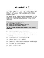
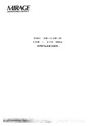
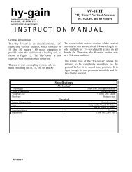
R O H N S O L U T I O N SU N D E R S T A N D I N G T I A - 2 2 2 - R E V I S I O N GIWhat is Exposure?Exposure categories are used to adjust wind loading based on the type of terrain surrounding a site. Reduced wind loads areassociated with rougher terrains that tend to slow the wind down. Three exposure categories have been defined based onterrain roughness. Wind loading is increased as the exposure designation changes from Exposure B (roughest terrain) toExposure D (smoothest terrain).Exposure B: Urban, suburban or wooded areas. The wind load at ground level is reduced compared to Exposure C. Thisreduction diminishes with height, making the overall wind reduction less significant for taller structures. In order to qualify forthe wind load reduction, the rough terrain must extend in all directions from the site at least twenty times the height of thestructure, but not less than one-half mile.Exposure C: Flat, open country and grasslands.Exposure D: Flat, unobstructed shorelines exposed to wind flowing over open water, smooth mud flats, salt flats and othersimilar terrain. The wind load at ground level is increased compared to Exposure C.Topographic CategoriesTopographic categories are used to determine increases in wind loading for sites located on hills and other elevated locations(other than buildings). The shape and relative height (topography) of an elevated site determines the increase in wind load.Although many elevated sites have their own unique features, the intent is to idealize these sites into one of the standardtopography categories described below.The height of an elevated site above the surrounding terrain must be specified in order to determine the increase in windloading. Height should not be confused with the elevation of the site. As described below, elevations of the site and thesurrounding terrain must be used to determine the relative height of a site. For structures supported on buildings, it is onlynecessary to specify the height of the building and the surrounding exposure category.Category 1: Flat or rolling terrain with no abrupt changes in general topography. No increase in wind loading is required forthis category.Category 2: Sites separated from a lower elevation by a gently sloping terrain (escarpment). Wind loads at the crest are 2.0times the wind loads for a flat site and diminish with height depending on the height of the escarpment.Height for an escarpment is the difference in elevation between the upper and lower levels. Increased wind loads do not applyfor structures located in the lower half of the sloping terrain or located beyond 16 times the escarpment’s height from the crest.Category 3: Sites located at the top or within the upper half of a hill. Wind loads at the top of a hill are 2.3 times the wind loadsfor a flat site and diminish with height depending on the relative height of the hill.Height for a hill is the difference in elevation between the top and bottom of the hill. For sites surrounded by other hills, heightis the difference in the hill elevation at the site and the average elevation of the surrounding hills (within a 2-mile radius).In other words, height is the projection of the hill exposed to wind. When there are other hills surrounding the site, increasedwind loads do not apply unless the height of the hill at the tower site is at least 2 times the average height of the surroundinghills. (Refer to sketch above.)Topographic Categories continued on next page.Phone (309) 566-3000 • Fax (309) 566-3079 • www.rohnnet.com • The Industry Standard© 2011 <strong>ROHN</strong> PRODUCTS <strong>LLC</strong>15
IR O H N S O L U T I O N SU N D E R S T A N D I N G T I A - 2 2 2 - R E V I S I O N GTowerElevation 2,150’Average Elevation ofSurrounding FeaturesElevation 1,550’Height of SiteAverage Heightof SurroundingTerrain300’ 600’Elevation 1,250’2 Mile Radius 2 Mile RadiusH = 2,150’ - 1,550‘ = 600’Wind speed-up must be considered when H exceeds2 times the average height of surrounding features.Category 4: Sites located on a ridge. Wind loads at the top of a ridge are 3 times the wind loads for a flat site and diminish withheight depending on the height of the ridge.Height for a ridge is the difference between the top and bottom elevations of the ridge.Category 5: This category is reserved for sites where site-specific investigations are performed to determine wind loading. Asite-specific investigation may result in either higher or lower wind loads compared to using one of the standard topographiccategories.16Phone (309) 566-3000 • Fax (309) 566-3079 • www.rohnnet.com • The Industry Standard© 2011 <strong>ROHN</strong> PRODUCTS <strong>LLC</strong>
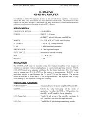
R O H N S O L U T I O N SR E V G 3 - S E C O N D B A S I C W I N D S P E E D M A PISpecial Wind RegionLocation V mph (m/s)Hawaii 105 (47)Puerto Rico 145 (66)Guam 170 (76)Virgin Islands 145 (65)American Samoa 125 (56)Notes:1. Values are 3-second gust wind speeds in miles per hour (m/s) at 33 ft. (10 m) above ground for Exposure C terrain.2. Linear interpolation between wind contours is permitted.3. Islands and coastal areas outside last contour must use the last wind speed contour of the coastal area.4. Mountainous terrain, gorges, ocean promontories, and special wind regions must be examined for unusualwind conditions.The basic wind speed map is being used with permission from ASCE. This material may be used for personal use only.Any other use requires prior permission of the American Society of Civil Engineers.Phone (309) 566-3000 • Fax (309) 566-3079 • www.rohnnet.com • The Industry Standard© 2011 <strong>ROHN</strong> PRODUCTS <strong>LLC</strong>17
IR O H N S O L U T I O N SR E V G W I N D S P E E D SThe TIA-222-G Standard is based on the wind map published in the ASCE 7-02 Standard, “Minimum Design Loads for Buildingsand Other Standards”. The ASCE 7 standard is published by the American Society of Civil Engineers (ASCE) and represents thelatest research and data available for wind speeds in the United States.Subsequent to the release of the TIA-222-G Standard, ASCE has published 2 revisions to the ASCE-7 Standard. The first revisionwas published in 2005 and is designated as ASCE 7-05. There were no changes to the wind map. The second revision waspublished in 2010 and is designated as ASCE 7-10. There are changes to the wind map in this version.The previous versions of ASCE 7 used a 50-year return wind speed map and relied on additional design factors to increasewind loads according to the reliability requirements of a structure. This resulted in structures being able to survive windspeeds of much higher return periods. The new wind maps in ASCE 7 -10 now include these design factors and nowrepresent a much higher return period wind speed. A wind map is provided for each classification of structure. Noadditional factors have to be considered based on the classification of a structure when these wind speeds are used tocalculate wind loads. The new maps can be thought of as “Survival” wind speeds, or in other words, wind speeds forwhich permanent deformation may occur in a structure, but the structure does not collapse.The new ASCE 7-10 survival wind speeds can be easily converted for use with the TIA-222-G Standard using the followingconversion table. If the conversion is not made, the design factors for determining wind loads will be “doubled up” resultingin much higher wind loads than intended. Eventually the TIA Standard and other similar structural standards will beupgraded to reflect the new ASCE 7-10 wind maps. Conversions for fastest-mile wind speeds used in Rev F andASCE 7-93 are also included in the table.Design Wind Speed Conversions, MPHRev FASCE 7-93(fastest-mile)7176859095104114123128133152Rev GASCE 7-02 & ASCE 7-05(3-second gust)8590100105110120130140145150170SurvivalASCE 7-10(3-second gust)110115126133139152164177183190215Examples to determine appropriate Rev G design criteria:1. Desire a 95 mph Rev F fastest-mile design. Use a 110 mph Rev G design.2. Desire a 115 mph ASCE 7-10 design. Use a 90 mph Rev G design.18Phone (309) 566-3000 • Fax (309) 566-3079 • www.rohnnet.com • The Industry Standard© 2011 <strong>ROHN</strong> PRODUCTS <strong>LLC</strong>
R O H N S O L U T I O N SR E V G G R O U N D I N GR E Q U I R E M E N T F O R S T R U C T U R E SRev G made significant changes regarding the grounding requirements for structures. A prescriptive approach to groundingwas used in Rev F where providing specific grounding leads and ground rods were considered adequate to protect a structure.Rev G adopted a performance specification approach that requires providing a grounding system that will result in a maximum10 ohm resistance to earth. Rev G also requires minimum ground lead and ground rod sizes that are greater than the Rev Fprescriptive requirements.Another change is that Rev G does not require specific grounding materials. Rev F required the use of galvanized ground rodswith tinned copper leads. Rev G only requires that the leads and connections be compatible with the ground rods from acorrosion standpoint (i.e. minimize difference between metals connected).Rev G does provide default grounding arrangements for various types of structures that are intended to meet the 10 ohmrequirement for a wide variety of soil conditions. In accordance with Rev G, the actual resistance of a default grounding systemmust be verified based on site conditions. Additional ground rods or special grounding systems may be required.It should be noted that the TIA-222 grounding requirements are meant to protect the structure and foundation from highfault currents. Other grounding requirements are often needed for the protection of antennas, radio equipment and otherappurtenances.R E V G S T A N D A R D F O U N D A T I O N SRev G has taken a different approach from Rev F regarding standard foundations and the term “Normal Soil” has beeneliminated. A new term “Presumptive Soil” has been introduced. Rev G provides for two different types of presumptive soil,sand and clay. Generally the strength of Rev G presumptive soil is lower than the strength of Rev F normal soil.The intent is to provide default design parameters that can be used to design foundations when a geotechnical report is notavailable for a site. In accordance with Rev G, clay is to be considered the default presumptive soil unless more information isknown about a site. The values for clay presumptive soil have therefore been used for the generation of the standardfoundations contained in this catalog.It should be noted that in accordance with Rev G, actual site conditions must be investigated prior to the installation of afoundation that was designed using presumptive soil parameters. Modifications to the standard foundations contained inthis catalog may be required. It should also be noted that Rev G requires a geotechnical investigation for all Class III structures.One common cause for changes to a standard foundation is due to frost depth. The frost depth for Rev G presumptive soil isconsidered to be 3.5 feet. The standard foundations in this catalog are based on this frost depth. Special foundations may berequired for sites in locations where frost depths exceed 3.5 feet and the local soil conditions are susceptible to frost heave.Presumptive soil also assumes that the water table is below the foundation depth. For this condition, there is no concern forbuoyant conditions that can significantly reduce the uplift capacity of a foundation. The standard foundations in this catalogare based on dry soil conditions and do not consider buoyant conditions. Special foundations may be required for sites wherethe water table may rise above the base elevation of the foundation.In accordance with Rev G, presumptive soils are also considered to be non-corrosive. When local soil conditions are corrosive,anchors or direct embedded poles that are in direct soil contact may require corrosion protection in addition to hot dipgalvanizing. Rev G provides guidance on various alternatives to consider in these situations.Presumptive soils are also considered to be non-expansive. Locations known to have expansive soil require specialconsiderations for foundation design. Modifications to the standard foundations in this catalog may be required in thesecases.Phone (309) 566-3000 • Fax (309) 566-3079 • www.rohnnet.com • The Industry Standard© 2011 <strong>ROHN</strong> PRODUCTS <strong>LLC</strong>I19
IR O H N S O L U T I O N SR E V G C L I M B I N G F A C I L I T I E SRev G has made significant additions addressing climber safety. Two classifications of climbers have been defined.An Authorized Climber (also called a Basic Climber) is an individual trained in climbing but may not have had previousclimbing experience. These climbers are intended to be limited to climbing fixed access routes equipped with safety climbdevices. A Competent Climber (also called a Skilled Climber) is a professional who is capable of climbing on structuralmembers.Rev G provides requirements for climbing facilities by defining two classes of climbing facilities, Class A and Class B.Class B requirements are similar to Rev F requirements and are intended for structures to be climbed by professionalCompetent Climbers. Class A requirements are more restrictive in comparison to Rev F and are intended for structuresexpected to be climbed by lesser qualified (Basic) climbers. In accordance with Rev G, Class B is considered to be thedefault climbing facility requirement for structures unless otherwise specified. Towers can be quoted to accomodateClass A climbing facilities when specified. All <strong>ROHN</strong> standard structures are intended to be climbed by CompetentClimbers only.Safety climb systems are now mandatory in accordance with Rev G for structures exceeding 10 feet in height that areintended to be climbed. Some structures are intended to be maintained by bucket trucks or other methods that do notinvolve climbing the structure. Safety climb systems, when required, must be ordered separately for all <strong>ROHN</strong> standardstructures in this catalog.20Phone (309) 566-3000 • Fax (309) 566-3079 • www.rohnnet.com • The Industry Standard© 2011 <strong>ROHN</strong> PRODUCTS <strong>LLC</strong>
GG - S E R I E S T O W E R S<strong>ROHN</strong> began manufacturing the G-Series line of towers in the early 1950’s. Starting with the <strong>ROHN</strong> No. 5 tower, there wasan ever present drive for a superior tower design. The No. 5 soon led to the <strong>ROHN</strong> No. 6 and continued through the No.10,11, 20, 25, 30, 40 and 50 towers. <strong>ROHN</strong> originally coated the lightweight towers with a hot-dipped enamel coatingcalled RohnKote. The alternative to RohnKote was hot-dipped galvanizing. The galvanized option was identified bythe now famous “G” suffix added to the tower model. The G-Series was born! The numbers have settled to the fourmodels listed below and hot-dip galvanizing is the coating of choice for towers today.<strong>ROHN</strong>’s G-Series towers are designed for strength and versatility. The towers are constructed with high strength steeltubing or solid round legs. <strong>ROHN</strong>’s exclusive Zig-Zag solid-rod bracing provides exceptional strength. As they were in the1950’s, each <strong>ROHN</strong> G-Series tower continues to be hot-dip galvanized for corrosion protection.25G | 45G | 55G | 65GThe 25G is a light weight tubular tower with solid braces. The tower sectionsare most often guyed, but can also be used in bracketed and self-supportingapplications. Standard sections are 10’ in length, but are also available ina 7‘ length, which is UPS shippable. This tower model has several topoptions, as well as a variety of tower accessories. The 25G has several baseoptions, including: base cast in concrete, base plate with anchor bolts andalso a hinged base.Standard Design Tower HeightsGuyed: Up to 190’Bracketed: Up to 100‘Self-Supporting: Up to 40’25G | 45G | 55G | 65GThe 45G is a light weight tower, available with tubular or solid round legswith solid braces. The tower sections are most often guyed, but can also beused in bracketed and self-supporting applications. Standard sections are10’ in length, but are also available in a 20‘ length when ordering solidsections. This tower model has several top options, as well as a variety oftower accessories. The 45G has several base options, including: base cast inconcrete, base plate with anchor bolts and also a hinged base. This toweris a true multi-use structure.Standard Design Tower HeightsGuyed: Up to 300’ [45G] and 350’ [45GSR]Bracketed: Up to 100‘Self-Supporting: Up to 45’22Phone (309) 566-3000 • Fax (309) 566-3079 • www.rohnnet.com • The Industry Standard© 2011 <strong>ROHN</strong> PRODUCTS <strong>LLC</strong>
G - S E R I E S T O W E R SG25G | 45G | 55G | 65GThe 55G is a tubular tower with solid braces that lends itself to a wide varietyof uses, particularly where unusual wind loading and height requirementsexist. The 55G was designed to provide excellent strength and rigidity. Thetower sections are most often guyed, but can also be used in bracketed andself-supporting applications. Standard sections are 10’ in length. This towermodel has several top options, as well as a variety of tower accessories.The 55G is available with a base cast in concrete as well as a tapered baseoption.Standard Design Tower HeightsGuyed: Up to 400’Bracketed: Up to 100‘Self-Supporting: Up to 60’The 65G is available with tubular or solid round legs with solid braces. Thetower sections are most often guyed, but can also be used in self-supportingapplications. Standard sections are 10’ and 20’ in length. This tower modelhas a variety of tower accessories, and is available with a base cast in concreteor a tapered base.Standard Design Tower HeightsGuyed: Up to 500’Self-Supporting: Up to 80’25G | 45G | 55G | 65GThe <strong>ROHN</strong> G-Series towers are assembled and installed quickly and are diverse enough for use by broadcasters, fire andpolice, military, ham and home use. The possibilities are endless with the G-Series towers. Over the long history of theG-Series, <strong>ROHN</strong> has developed a variety of options to improve the utility of each model. The G-Series has optional:• Standard and Shortened Sections • Double Braced Sections • House Brackets• Guy Lug Sections • Torque Arms • Base Options• Four Leg (Square) Design of 25G • Roof Mounts • Side Arms• Double Braced Sections• Top MountsPhone (309) 566-3000 • Fax (309) 566-3079 • www.rohnnet.com • The Industry Standard© 2011 <strong>ROHN</strong> PRODUCTS <strong>LLC</strong>23
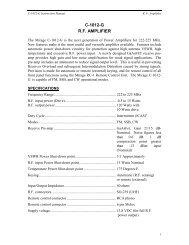
GG U Y E D T O W E R S - 2 5 GS T A N D A R D 2 5 G G U Y E D T O W E R<strong>ROHN</strong> 25GThe first. The original.includesREV. F &REV. G25GGENERAL USEThe 25G is available in the standard 10’ sectionlength and a 7’ length which is UPS shippable.The 25G uses double bolted joints, proven to bethe best method of joining tower sections forsturdiness and dependability. As a guyedstructure, the 25G standard designs rise to aheight of 190’.FEATURES• Completely hot-dip galvanized after fabrication• Built on an 11 1/4” equilateral triangle design• High strength tubular legs joined by Zig-Zag ®cross members• Each 7’ or 10’ section contains all required nutsand bolts shipped with section• Continuous solid round steel bracingCAUTIONMixing copies of <strong>ROHN</strong> towers with <strong>ROHN</strong> towers is dangerous and voids allengineering and warranty data supplied by <strong>ROHN</strong>. Materials used by others arenot the same quality and have not been tested or engineered by <strong>ROHN</strong>. Mixing<strong>ROHN</strong> tower sections with non-<strong>ROHN</strong> products may cause tower failure or injury.Per Rev G requirements, any structure greater than 10’ requires a climbersafety device. Please see page 40 for ordering information.24Phone (309) 566-3000 • Fax (309) 566-3079 • www.rohnnet.com • The Industry Standard© 2011 <strong>ROHN</strong> PRODUCTS <strong>LLC</strong>
G U Y E D T O W E R S - 2 5 GS T A N D A R D 2 5 G G U Y E D T O W E RS E C T I O N SG6 1/2”9 3/4”11 1/4”QUICK REFERENCEPARTS & ACCESSORIES PAGES 37-40GROUNDING INFORMATION PAGE 41FOUNDATION INFORMATION PAGES 41-441’ 6”2.25” O.D.2.08” I.D.(14 GA.)Optional WaveguideBrackets (KY2041A)9’ 9”1’ 3”1 1/4” O.D.(16 GA.)1 1/4” O.D.(16 GA.)5/16” O.D.Solid Bracing~5/16” O.D.Solid BracingOptional double braced sectionsare available upon request.STANDARD TOP SECTION25AG2Additional 25G top sectionsare shown on page 37.STANDARD SECTION25G - 10’ SectionOPTIONAL 7’ SECTION25G7 - 7‘ SectionThe 7’ Section is UPS shippable.Phone (309) 566-3000 • Fax (309) 566-3079 • www.rohnnet.com • The Industry Standard© 2011 <strong>ROHN</strong> PRODUCTS <strong>LLC</strong>CONCRETE BASE PLATEBPC25G*FOR USE WITH 3/4X12PP PIER PINEMBEDDED IN CONCRETE.Additional base sections areavailable, please see page 38.* Towers mounted on these bases must be bracketed or guyed at all times. Temporary steel guying may also be necessary during installation and dismantling.25
GG U Y E D T O W E R S - 2 5 GB U Y E R S G U I D ES T A N D A R D D E S I G N S - 2 5 G9 0 M P H R E V . G [ 3 - S E C O N D G U S T ]7 0 M P H R E V . F [ F A S T E S T M I L E ]Design CriteriaEPA (SQ. FT.) For Exposure B, Revision G35’22.647’22.03/16” EHS(399#)16.6P/N 25G90R04032’EPA (SQ. FT.) For Exposure C, Revision GEPA (SQ. FT.), Revision FGuy Initial TensionP/N 25G90R040Tower ModelTower Height (ft.)Windspeed (Rev. G) <strong>ROHN</strong> TowerEPA= Effective Projected AreaThis document is to serve as a guide for sizing and purchasing the 25G tower. Tower and foundation installations shouldbe performed by qualified and experienced personnel using assembly drawings provided with each tower.DESIGN NOTES:1. Tower designs are in accordance with ANSI/TIA-222-F and ANSI/TIA-222-G, Class I Structures, Topographic Category 1.2. Design assumes towers are installed on level ground. Lower EPA values will apply for roof mounted towers or for siteslocated on unusual terrain.3. Designs assume two 1/2” diameter lines on each tower face.4. Anchor radius is from tower base to intersection of anchor rod with ground.5. Guy chord lengths shown are based on level ground. Initial tensions for guys are shown in ( ) in pounds at 60º Fahrenheit.6. Antenna and mounts are assumed symmetrically placed at the tower top.PARTS LIST NOTES:1. Items listed are required for complete guyed towers.2. Base and anchor foundations listed refer to standard foundation designations.3. Guys provided with each standard tower are based on level ground conditions with an additional 6% length.4. Rev G anchor grounding (AGK1GGX) and base grounding (BGK3GGX) are included with the tower material.5. Assembly drawings and a safety package (P/N: ACWS) are included with each tower.6. Parts lists are subject to change based on availability or revised design criteria.FOR FOUNDATION INFORMATION, PLEASE SEE PAGES 41-44.FOR GENERAL INSTALLATION INFORMATION, PLEASE SEE PAGES 147-153.26Phone (309) 566-3000 • Fax (309) 566-3079 • www.rohnnet.com • The Industry Standard© 2011 <strong>ROHN</strong> PRODUCTS <strong>LLC</strong>
G U Y E D T O W E R S - 2 5 GS T A N D A R D D E S I G N - 2 5 G9 0 M P H R E V . G , 7 0 M P H R E V . FG35’40’ TOWER22.6 OR 16.647’22.03/16” EHS(399#)32’P/N: 25G90R040TOWER PARTSINCLUDEDGUYS &CONNECTIONSINCLUDEDANCHORS &GROUNDINGINCLUDED25G 25AG2 BPC25G GA25GD3 1 1 13/16EHS BG2142 5/16THH 1/2TBE&J TBSAFETY175’ 6 6 3 3GAC3455TOP AGK1GGX BGK3GGX CPC.5/.753 1 3 3FDNSBASE ANCHORCB1G3/4x12PP1AB240’ <strong>ROHN</strong> 25GAll par ts shown in tableare included when orderingPar t No: 25G90R04045’23’50’ TOWER21.4 OR 15.860’46’21.03/16” EHS(399#)40’P/N: 25G90R050TOWER PARTSINCLUDEDGUYS &CONNECTIONSINCLUDEDANCHORS &GROUNDINGINCLUDED25G 25AG2 BPC25G GA25GD4 1 1 23/16EHS BG2142 5/16THH 1/2TBE&J TBSAFETY350’ 12 12 6 3GAC3455TOP AGK1GGX BGK3GGX CPC.5/.753 1 3 3FDNSBASE ANCHORCB1G3/4x12PP1AB250’ <strong>ROHN</strong> 25GAll par ts shown in tableare included when orderingPar t No: 25G90R05055’28’60’ TOWER20.3 OR 15.273’56’20.23/16” EHS(399#)48’P/N: 25G90R060TOWER PARTSINCLUDEDGUYS &CONNECTIONSINCLUDEDANCHORS &GROUNDINGINCLUDED25G 25AG2 BPC25G GA25GD5 1 1 23/16EHS BG2142 5/16THH 1/2TBE&J TBSAFETY425’ 12 12 6 3GAC3455TOP AGK1GGX BGK3GGX CPC.5/.753 1 3 3FDNSBASE ANCHORCB1G3/4x12PP1AB260’ <strong>ROHN</strong> 25GAll par ts shown in tableare included when orderingPar t No: 25G90R06065’32’70’ TOWER19.4 OR 14.786’64’19.43/16” EHS(399#)56’P/N: 25G90R070TOWER PARTSINCLUDEDGUYS &CONNECTIONSINCLUDEDANCHORS &GROUNDINGINCLUDED25G 25AG2 BPC25G GA25GD6 1 1 23/16EHS BG2142 5/16THH 1/2TBE&J TBSAFETY500’ 12 12 6 3GAC3455TOP AGK1GGX BGK3GGX CPC.5/.753 1 3 3FDNSBASE ANCHORCB1G3/4x12PP1AB270’ <strong>ROHN</strong> 25GAll par ts shown in tableare included when orderingPar t No: 25G90R07075’50’80’ TOWER18.6 OR 14.399’81’25’ 69’18.83/16” EHS(399#)64’P/N: 25G90R080TOWER PARTSINCLUDEDGUYS &CONNECTIONSINCLUDEDANCHORS &GROUNDINGINCLUDED25G 25AG2 BPC25G GA25GD7 1 1 33/16EHS BG2142 5/16THH 1/2TBE&J TBSAFETY800’ 18 18 9 3GAC3455TOP AGK1GGX BGK3GGX CPC.5/.753 1 3 3FDNSBASE ANCHORCB1G3/4x12PP1AB280’ <strong>ROHN</strong> 25GAll par ts shown in tableare included when orderingPar t No: 25G90R080Phone (309) 566-3000 • Fax (309) 566-3079 • www.rohnnet.com • The Industry Standard© 2011 <strong>ROHN</strong> PRODUCTS <strong>LLC</strong>27
GG U Y E D T O W E R S - 2 5 GS T A N D A R D D E S I G N - 2 5 G9 0 M P H R E V . G , 7 0 M P H R E V . F85’57’90’ TOWER18.0 OR 13.9111’92’18.43/16” EHS(399#)TOWER PARTSINCLUDEDGUYS &CONNECTIONSINCLUDED25G 25AG2 BPC25G GA25GD8 1 1 3FDNSBASE ANCHORCB1G3/16EHS BG2142 5/16THH 1/2TBE&J TBSAFETY900’ 18 18 9 3AB290’ <strong>ROHN</strong> 25GAll par ts shown in tableare included when orderingPar t No: 25G90R09028’ 77’72’P/N: 25G90R090ANCHORS &GROUNDINGINCLUDEDGAC3455TOP AGK1GGX BGK3GGX CPC.5/.753 1 3 33/4x12PP195’63’100’ TOWER17.5 OR 13.6124’102’31’ 86’18.03/16” EHS(399#)80’P/N: 25G90R100TOWER PARTSINCLUDEDGUYS &CONNECTIONSINCLUDEDANCHORS &GROUNDINGINCLUDED25G 25AG2 BPC25G GA25GD9 1 1 33/16EHS BG2142 5/16THH 1/2TBE&J TBSAFETY1000’ 18 18 9 3GAC3455TOP AGK1GGX BGK3GGX CPC.5/.753 1 3 3FDNSBASE ANCHORCB1G3/4x12PP1AB2100’ <strong>ROHN</strong> 25GAll par ts shown in tableare included when orderingPar t No: 2590R100105’70’110’ TOWER17.0 OR 13.4137’112’17.63/16” EHS(399#)TOWER PARTSINCLUDEDGUYS &CONNECTIONSINCLUDED25G 25AG2 BPC25G GA25GD10 1 1 3FDNSBASE ANCHORCB1G3/16EHS BG2142 5/16THH 1/2TBE&J TBSAFETY1100’ 18 18 9 3AB2110’ <strong>ROHN</strong> 25GAll par ts shown in tableare included when orderingPar t No: 25G90R11035’ 95’88’P/N: 25G90R110ANCHORS &GROUNDINGINCLUDEDGAC3455TOP AGK1GGX BGK3GGX CPC.5/.753 1 3 33/4x12PP1115’85’55’120’ TOWER16.6 OR 13.1150’128’111’28’ 100’17.23/16” EHS(399#)96’P/N: 25G90R120TOWER PARTSINCLUDEDGUYS &CONNECTIONSINCLUDEDANCHORS &GROUNDINGINCLUDED25G 25AG2 BPC25G GA25GD11 1 1 43/16EHS BG2142 5/16THH 1/2TBE&J TBSAFETY1575’ 24 24 12 3GAC3455TOP AGK1GGX BGK3GGX CPC.5/.753 1 3 3FDNSBASE ANCHORCB1G3/4x12PP1AB2120’ <strong>ROHN</strong> 25GAll par ts shown in tableare included when orderingPar t No: 25G90R120125’93’62’130’ TOWER16.2 OR 12.9163’140’121’31’ 108’17.03/16” EHS(399#)104’P/N: 25G90R130TOWER PARTSINCLUDEDGUYS &CONNECTIONSINCLUDEDANCHORS &GROUNDINGINCLUDED25G 25AG2 BPC25G GA25GD12 1 1 43/16EHS BG2142 5/16THH 1/2TBE&J TBSAFETY1700’ 24 24 12 3GAC3455TOP AGK1GGX BGK3GGX CPC.5/.753 1 3 3FDNSBASE ANCHORCB1G3/4x12PP1AB2130’ <strong>ROHN</strong> 25GAll par ts shown in tableare included when orderingPar t No: 25G90R13028Phone (309) 566-3000 • Fax (309) 566-3079 • www.rohnnet.com • The Industry Standard© 2011 <strong>ROHN</strong> PRODUCTS <strong>LLC</strong>
G U Y E D T O W E R S - 2 5 GGS T A N D A R D D E S I G N - 2 5 G9 0 M P H R E V . G , 7 0 M P H R E V . F135’99’66’140’ TOWER15.9 OR 12.7175’149’130’33’ 117’16.63/16” EHS(399#)112’P/N: 25G90R140TOWER PARTSINCLUDEDGUYS &CONNECTIONSINCLUDEDANCHORS &GROUNDINGINCLUDED25G 25AG2 BPC25G GA25GD13 1 1 43/16EHS BG2142 5/16THH 1/2TBE&J TBSAFETY1825’ 24 24 12 3GAC3455TOP AGK1GGX BGK3GGX CPC.5/.753 1 3 3FDNSBASE ANCHORCB1G3/4x12PP1AB2140’ <strong>ROHN</strong> 25GAll par ts shown in tableare included when orderingPar t No: 25G90R140145’116’87’58’29’150’ TOWER15.5 OR 12.5188’167’148’133’123’16.43/16” EHS(399#)120’P/N: 25G90R150TOWER PARTSINCLUDEDGUYS &CONNECTIONSINCLUDEDANCHORS &GROUNDINGINCLUDED25G 25AG2 BPC25G GA25GD14 1 1 53/16EHS BG2142 5/16THH 1/2TBE&J TBSAFETY2425’ 30 30 15 3GAC3455TOP AGK1GGX BGK3GGX CPC.5/.753 1 3 3FDNSBASE ANCHORCB1G3/4x12PP1AB2150’ <strong>ROHN</strong> 25GAll par ts shown in tableare included when orderingPar t No: 25G90R150155’124’93’62’31’160’ TOWER15.3 OR 12.3201’178’158’142’132’16.23/16” EHS(399#)128’P/N: 25G90R160TOWER PARTSINCLUDEDGUYS &CONNECTIONSINCLUDEDANCHORS &GROUNDINGINCLUDED25G 25AG2 BPC25G GA25GD15 1 1 53/16EHS BG2142 5/16THH 1/2TBE&J TBSAFETY2600’ 30 30 15 3GAC3455TOP AGK1GGX BGK3GGX CPC.5/.753 1 3 3FDNSBASE ANCHORCB1G3/4x12PP1AB2160’ <strong>ROHN</strong> 25GAll par ts shown in tableare included when orderingPar t No: 25G90R160165’132’99’66’33’170’ TOWER15.0 OR 12.2214’190’168’151’140’16.03/16” EHS(399#)136’P/N: 25G90R170TOWER PARTSINCLUDEDGUYS &CONNECTIONSINCLUDEDANCHORS &GROUNDINGINCLUDED25G 25AG2 BPC25G GA25GD16 1 1 53/16EHS BG2142 5/16THH 1/2TBE&J TBSAFETY2750’ 30 30 15 3GAC3455TOP AGK1GGX BGK3GGX CPC.5/.753 1 3 3FDNSBASE ANCHORCB1G3/4x12PP1AB2170’ <strong>ROHN</strong> 25GAll par ts shown in tableare included when orderingPar t No: 25G90R170175’139’105’69’35’180’ TOWER14.8 OR 12.0227’200’178’160’148’15.83/16” EHS(399#)144’P/N: 25G90R180TOWER PARTSINCLUDEDGUYS &CONNECTIONSINCLUDEDANCHORS &GROUNDINGINCLUDED25G 25AG2 BPC25G GA25GD17 1 1 53/16EHS BG2142 5/16THH 1/2TBE&J TBSAFETY2925’ 30 30 15 3GAC3455TOP AGK1GGX BGK3GGX CPC.5/.753 1 3 3FDNSBASE ANCHORCB1G3/4x12PP1AB2180’ <strong>ROHN</strong> 25GAll par ts shown in tableare included when orderingPar t No: 25G90R180Phone (309) 566-3000 • Fax (309) 566-3079 • www.rohnnet.com • The Industry Standard© 2011 <strong>ROHN</strong> PRODUCTS <strong>LLC</strong>29
GG U Y E D T O W E R S - 2 5 GS T A N D A R D D E S I G N - 2 5 G9 0 M P H R E V . G , 7 0 M P H R E V . F185’148’111’74’190’ TOWER14.5 OR 11.9239’212’188’169’15.63/16” EHS(399#)TOWER PARTSINCLUDEDGUYS &CONNECTIONSINCLUDED25G 25AG2 BPC25G GA25GD18 1 1 5FDNSBASE ANCHORCB1G3/16EHS BG2142 5/16THH 1/2TBE&J TBSAFETY3075’ 30 30 15 3AB2190’ <strong>ROHN</strong> 25GAll par ts shown in tableare included when orderingPar t No: 25G90R19037’ 156’152’P/N: 25G90R190ANCHORS &GROUNDINGINCLUDEDGAC3455TOP AGK1GGX BGK3GGX3 1 3CPC.5/.7533/4x12PP130Phone (309) 566-3000 • Fax (309) 566-3079 • www.rohnnet.com • The Industry Standard© 2011 <strong>ROHN</strong> PRODUCTS <strong>LLC</strong>
G U Y E D T O W E R S - 2 5 GGS T A N D A R D D E S I G N - 2 5 G1 1 0 M P H R E V . G , 9 0 M P H R E V . F35’40’ TOWER13.4 OR 9.747’13.43/16” EHS(399#)TOWER PARTSINCLUDEDGUYS &CONNECTIONSINCLUDED25G 25AG2 BPC25G GA25GD3 1 1 1FDNSBASE ANCHORCB1G3/16EHS BG2142 5/16THH 1/2TBE&J TBSAFETY175’ 6 6 3 3AB240’ <strong>ROHN</strong> 25GAll par ts shown in tableare included when orderingPar t No: 25G110R04032’P/N: 25G110R040ANCHORS &GROUNDINGINCLUDEDGAC3455TOP AGK1GGX BGK3GGX CPC.5/.753 1 3 33/4x12PP145’22’50’ TOWER12.6 OR 9.160’46’12.63/16” EHS(399#)40’P/N: 25G110R050TOWER PARTSINCLUDEDGUYS &CONNECTIONSINCLUDEDANCHORS &GROUNDINGINCLUDED25G 25AG2 BPC25G GA25GD4 1 1 23/16EHS BG2142 5/16THH 1/2TBE&J TBSAFETY350’ 12 12 6 3GAC3455TOP AGK1GGX BGK3GGX CPC.5/.753 1 3 3FDNSBASE ANCHORCB1G3/4x12PP1AB250’ <strong>ROHN</strong> 25GAll par ts shown in tableare included when orderingPar t No: 25G110R05055’28’60’ TOWER11.9 OR 8.773’56’12.23/16” EHS(399#)48’P/N: 25G110R060TOWER PARTSINCLUDEDGUYS &CONNECTIONSINCLUDEDANCHORS &GROUNDINGINCLUDED25G 25AG2 BPC25G GA25GD5 1 1 23/16EHS BG2142 5/16THH 1/2TBE&J TBSAFETY425’ 12 12 6 3GAC3455TOP AGK1GGX BGK3GGX CPC.5/.753 1 3 3FDNSBASE ANCHORCB1G3/4x12PP1AB260’ <strong>ROHN</strong> 25GAll par ts shown in tableare included when orderingPar t No: 25G110R06065’32’70’ TOWER11.3 OR 8.686’64’11.83/16” EHS(399#)TOWER PARTSINCLUDEDGUYS &CONNECTIONSINCLUDED25G 25AG2 BPC25G GA25GD6 1 1 2FDNSBASE ANCHORCB1G3/16EHS BG2142 5/16THH 1/2TBE&J TBSAFETY500’ 12 12 6 3AB270’ <strong>ROHN</strong> 25GAll par ts shown in tableare included when orderingPar t No: 25G110R07056’P/N: 25G110R070ANCHORS &GROUNDINGINCLUDEDGAC3455TOP AGK1GGX BGK3GGX CPC.5/.753 1 3 33/4x12PP175’50’80’ TOWER10.9 OR 8.399’81’11.43/16” EHS(399#)TOWER PARTSINCLUDEDGUYS &CONNECTIONSINCLUDED25G 25AG2 BPC25G GA25GD7 1 1 3FDNSBASE ANCHORCB1G3/16 EHS BG2142 5/16 THH 1/2TBE&J TBSAFETY800’ 18 18 9 3AB280’ <strong>ROHN</strong> 25GAll par ts shown in tableare included when orderingPar t No: 25G110R08025’ 69’64’P/N: 25G110R080ANCHORS &GROUNDINGINCLUDEDGAC3455TOP AGK1GGX BGK3GGX CPC.5/.753 1 3 33/4x12PP1Phone (309) 566-3000 • Fax (309) 566-3079 • www.rohnnet.com • The Industry Standard© 2011 <strong>ROHN</strong> PRODUCTS <strong>LLC</strong>31
GG U Y E D T O W E R S - 2 5 GS T A N D A R D D E S I G N - 2 5 G1 1 0 M P H R E V . G , 9 0 M P H R E V . F85’56’90’ TOWER10.5 OR 8.1111’91’28’ 77’11.23/16” EHS(399#)72’P/N: 25G110R090TOWER PARTSINCLUDEDGUYS &CONNECTIONSINCLUDEDANCHORS &GROUNDINGINCLUDED25G 25AG2 BPC25G GA25GD8 1 1 33/16EHS BG2142 5/16THH 1/2TBE&J TBSAFETY900’ 18 18 9 3GAC3455TOP AGK1GGX BGK3GGX CPC.5/.753 1 3 3FDNSBASE ANCHORCB1G3/4x12PP1AB290’ <strong>ROHN</strong> 25GAll par ts shown in tableare included when orderingPar t No: 25G110R09095’63’100’ TOWER10.2 OR 7.9124’102’32’ 86’10.83/16” EHS(399#)80’P/N: 25G110R100TOWER PARTSINCLUDEDGUYS &CONNECTIONSINCLUDEDANCHORS &GROUNDINGINCLUDED25G 25AG2 BPC25G GA25GD9 1 1 33/16EHS BG2142 5/16THH 1/2TBE&J TBSAFETY1000’ 18 18 9 3GAC3455TOP AGK1GGX BGK3GGX CPC.5/.753 1 3 3FDNSBASE ANCHORCB1G3/4x12PP1AB2100’ <strong>ROHN</strong> 25GAll par ts shown in tableare included when orderingPar t No: 25G110R100105’70’110’ TOWER9.9 OR 7.8137’112’35’ 95’10.63/16” EHS(399#)88’P/N: 25G110R110TOWER PARTSINCLUDEDGUYS &CONNECTIONSINCLUDEDANCHORS &GROUNDINGINCLUDED25G 25AG2 BPC25G GA25GD10 1 1 33/16EHS BG2142 5/16THH 1/2TBE&J TBSAFETY1100’ 18 18 9 3GAC3455TOP AGK1GGX BGK3GGX CPC.5/.753 1 3 3FDNSBASE ANCHORCB1G3/4x12PP1AB2110’ <strong>ROHN</strong> 25GAll par ts shown in tableare included when orderingPar t No: 25G110R110115’86’57’120’ TOWER9.7 OR 7.6150’129’112’28’ 100’10.43/16” EHS(399#)96’P/N: 25G110R120TOWER PARTSINCLUDEDGUYS &CONNECTIONSINCLUDEDANCHORS &GROUNDINGINCLUDED25G 25AG2 BPC25G GA25GD11 1 1 43/16EHS BG2142 5/16THH 1/2TBE&J TBSAFETY1575’ 24 24 12 3GAC3455TOP AGK1GGX BGK3GGX CPC.5/.753 1 3 3FDNSBASE ANCHORCB1G3/4x12PP1AB2120’ <strong>ROHN</strong> 25GAll par ts shown in tableare included when orderingPar t No: 25G110R120125’93’62’130’ TOWER9.3 OR 7.5163’140’121’31’ 109’10.23/16” EHS(399#)104’P/N: 25G110R130TOWER PARTSINCLUDEDGUYS &CONNECTIONSINCLUDEDANCHORS &GROUNDINGINCLUDED25G 25AG2 BPC25G GA25GD12 1 1 43/16EHS BG2142 5/16THH 1/2TBE&J TBSAFETY1700’ 24 24 12 3GAC3455TOP AGK1GGX BGK3GGX CPC.5/.753 1 3 3FDNSBASE ANCHORCB1G3/4x12PP1AB2130’ <strong>ROHN</strong> 25GAll par ts shown in tableare included when orderingPar t No: 25G110R13032Phone (309) 566-3000 • Fax (309) 566-3079 • www.rohnnet.com • The Industry Standard© 2011 <strong>ROHN</strong> PRODUCTS <strong>LLC</strong>
G U Y E D T O W E R S - 2 5 GGS T A N D A R D D E S I G N - 2 5 G1 1 0 M P H R E V . G , 9 0 M P H R E V . F135’101’67’140’ TOWER9.2 OR 7.4175’151’131’33’ 117’10.03/16” EHS(399#)112’P/N: 25G110R140TOWER PARTSINCLUDEDGUYS &CONNECTIONSINCLUDEDANCHORS &GROUNDINGINCLUDED25G 25AG2 BPC25G GA25GD13 1 1 43/16EHS BG2142 5/16THH 1/2TBE&J TBSAFETY1825’ 24 24 12 3GAC3455TOP AGK1GGX BGK3GGX CPC.5/.753 1 3 3FDNSBASE ANCHORCB1G3/4x12PP1AB2140’ <strong>ROHN</strong> 25GAll par ts shown in tableare included when orderingPar t No: 25G110R140145’116’87’58’150’ TOWER9.0 OR 7.3188’167’148’133’9.93/16” EHS(399#)TOWER PARTSINCLUDEDGUYS &CONNECTIONSINCLUDED25G 25AG2 BPC25G GA25GD14 1 1 5FDNSBASE ANCHORCB1G3/16EHS BG2142 5/16THH 1/2TBE&J TBSAFETY2425’ 30 30 15 3AB2150’ <strong>ROHN</strong> 25GAll par ts shown in tableare included when orderingPar t No: 25G110R15029’ 123’120’P/N: 25G110R150ANCHORS &GROUNDINGINCLUDEDGAC3455TOP AGK1GGX BGK3GGX CPC.5/.753 1 3 33/4x12PP1155’124’93’62’160’ TOWER8.8 OR 7.2201’178’158’142’31’ 132’9.83/16” EHS(399#)128’P/N: 25G110R160TOWER PARTSINCLUDEDGUYS &CONNECTIONSINCLUDEDANCHORS &GROUNDINGINCLUDED25G 25AG2 BPC25G GA25GD15 1 1 53/16EHS BG2142 5/16THH 1/2TBE&J TBSAFETY2600’ 30 30 15 3GAC3455TOP AGK1GGX BGK3GGX CPC.5/.753 1 3 3FDNSBASE ANCHORCB1G3/4x12PP1AB2160’ <strong>ROHN</strong> 25GAll par ts shown in tableare included when orderingPar t No: 25G110R160165’138’110’83’55’170’ TOWER8.7 OR 7.174’28’ 57’214’194’175’159’9.73/16” EHS(399#)50’ 136’P/N: 25G110R170TOWER PARTSINCLUDEDGUYS &CONNECTIONSINCLUDEDANCHORS &GROUNDINGINCLUDED25G 25AG2 BPC25G GA25GD16 1 1 63/16EHS BG2142 5/16THH 1/2TBE&J TBSAFETY2800’ 36 36 18 6GAC3455TOP AGK1GGX BGK3GGX62 3CPC.5/.756BASECB2G3/4x12PP1INNERANCHORAB2OUTERANCHORAB2170’ <strong>ROHN</strong> 25GAll par ts shown intable are includedwhen orderingPar t No: 25G110R170176’145’116’87’58’77’29’ 58’180’ TOWER8.6 OR 7.0227’204’185’168’9.63/16” EHS(399#)50’ 144’P/N: 25G110R180TOWER PARTSINCLUDEDGUYS &CONNECTIONSINCLUDEDANCHORS &GROUNDINGINCLUDED25G 25AG2 BPC25G GA25GD17 1 1 63/16EHS BG2142 5/16THH 1/2TBE&J TBSAFETY2925’ 36 36 18 6GAC3455TOP AGK1GGX BGK3GGX62 3CPC.5/.756BASECB2G3/4x12PP1INNERANCHORAB2OUTERANCHORAB2180’ <strong>ROHN</strong> 25GAll par ts shown intable are includedwhen orderingPar t No: 25G110R180Phone (309) 566-3000 • Fax (309) 566-3079 • www.rohnnet.com • The Industry Standard© 2011 <strong>ROHN</strong> PRODUCTS <strong>LLC</strong>33
GG U Y E D T O W E R S - 2 5 GS T A N D A R D D E S I G N - 2 5 G1 1 0 M P H R E V . G , 9 0 M P H R E V . F186’155’124’93’62’190’ TOWER8.5 OR 6.980’31’ 59’240’217’196’178’9.53/16” EHS(399#)50’ 152’P/N: 25G110R190TOWER PARTSINCLUDEDGUYS &CONNECTIONSINCLUDEDANCHORS &GROUNDINGINCLUDED25G 25AG2 BPC25G GA25GD18 1 1 63/16EHS BG2142 5/16THH3100’ 36 36GAC3455TOP AGK1GGX BGK3GGX6 231/2TBE&J18CPC.5/.756BASECB2GTBSAFETY63/4x12PP1INNERANCHORAB2OUTERANCHORAB2190’ <strong>ROHN</strong> 25GAll par ts shown intable are includedwhen orderingPar t No: 25G110R19034Phone (309) 566-3000 • Fax (309) 566-3079 • www.rohnnet.com • The Industry Standard© 2011 <strong>ROHN</strong> PRODUCTS <strong>LLC</strong>
G U Y E D T O W E R S - 2 5 GGS T A N D A R D D E S I G N - 2 5 G1 3 0 M P H R E V . G , 1 1 0 M P H R E V . F38’40’ TOWER10.8 OR 7.950’11.23/16” EHS(399#)32’P/N: 25G130R040TOWER PARTSINCLUDEDGUYS &CONNECTIONSINCLUDEDANCHORS &GROUNDINGINCLUDED25G 25AG2 BPC25G GA25GD3 1 1 13/16EHS BG2142 5/16THH 1/2TBE&J TBSAFETY175’ 6 6 3 3GAC3455TOP AGK1GGX BGK3GGX CPC.5/.753 1 3 3FDNSBASE ANCHORCB1G3/4x12PP1AB240’ <strong>ROHN</strong> 25GAll par ts shown in tableare included when orderingPar t No: 25G130R04048’22’50’ TOWER10.1 OR 7.562’46’10.03/16” EHS(399#)TOWER PARTSINCLUDEDGUYS &CONNECTIONSINCLUDED25G 25AG2 BPC25G GA25GD4 1 1 2FDNSBASE ANCHORCB1G3/16EHS BG2142 5/16THH 1/2TBE&J TBSAFETY350’ 12 12 6 3AB250’ <strong>ROHN</strong> 25GAll par ts shown in tableare included when orderingPar t No: 25G130R05040’P/N: 25G130R050ANCHORS &GROUNDINGINCLUDEDGAC3455TOP AGK1GGX BGK3GGX CPC.5/.753 1 3 33/4x12PP158’28’60’ TOWER9.7 OR 7.275’56’9.83/16” EHS(399#)TOWER PARTSINCLUDEDGUYS &CONNECTIONSINCLUDED25G 25AG2 BPC25G GA25GD5 1 1 2FDNSBASE ANCHORCB1G3/16EHS BG2142 5/16THH 1/2TBE&J TBSAFETY425’ 12 12 6 3AB260’ <strong>ROHN</strong> 25GAll par ts shown in tableare included when orderingPar t No: 25G130R06048’P/N: 25G130R060ANCHORS &GROUNDINGINCLUDEDGAC3455TOP AGK1GGX BGK3GGX CPC.5/.753 1 3 33/4x12PP168’32’70’ TOWER9.2 OR 7.088’64’9.63/16” EHS(399#)TOWER PARTSINCLUDEDGUYS &CONNECTIONSINCLUDED25G 25AG2 BPC25G GA25GD6 1 1 2FDNSBASE ANCHORCB1G3/16EHS BG2142 5/16THH 1/2TBE&J TBSAFETY500’ 12 12 6 3AB270’ <strong>ROHN</strong> 25GAll par ts shown in tableare included when orderingPar t No: 25G130R07056’P/N: 25G130R070ANCHORS &GROUNDINGINCLUDEDGAC3455TOP AGK1GGX BGK3GGX CPC.5/.753 1 3 33/4x12PP178’50’80’ TOWER8.9 OR 6.8101’81’9.43/16” EHS(399#)TOWER PARTSINCLUDEDGUYS &CONNECTIONSINCLUDED25G 25AG2 BPC25G GA25GD7 1 1 3FDNSBASE ANCHORCB1G3/16EHS BG2142 5/16THH 1/2TBE&J TBSAFETY800’ 18 18 9 3AB280’ <strong>ROHN</strong> 25GAll par ts shown in tableare included when orderingPar t No: 25G130R08025’ 69’64’P/N: 25G130R080ANCHORS &GROUNDINGINCLUDEDGAC3455TOP AGK1GGX BGK3GGX CPC.5/.753 1 3 33/4x12PP1Phone (309) 566-3000 • Fax (309) 566-3079 • www.rohnnet.com • The Industry Standard© 2011 <strong>ROHN</strong> PRODUCTS <strong>LLC</strong>35
GG U Y E D T O W E R S - 2 5 GS T A N D A R D D E S I G N - 2 5 G1 3 0 M P H R E V . G , 1 1 0 M P H R E V . F88’56’90’ TOWER8.6 OR 6.7114’91’28’ 77’9.23/16” EHS(399#)72’P/N: 25G130R090TOWER PARTSINCLUDEDGUYS &CONNECTIONSINCLUDEDANCHORS &GROUNDINGINCLUDED25G 25AG2 BPC25G GA25GD8 1 1 33/16EHS BG2142 5/16THH 1/2TBE&J900’ 18 18 9 3GAC3455TOP AGK1GGX BGK3GGXCPC.5/.753 1 3 3FDNSBASE ANCHORCB1GTBSAFETY3/4x12PP1AB290’ <strong>ROHN</strong> 25GAll par ts shown in tableare included when orderingPar t No: 25G130R09098’63’100’ TOWER8.3 OR 6.5127’102’32’ 86’9.03/16” EHS(399#)80’P/N: 25G130R100TOWER PARTSINCLUDEDGUYS &CONNECTIONSINCLUDEDANCHORS &GROUNDINGINCLUDED25G 25AG2 BPC25G GA25GD9 1 1 33/16EHS BG2142 5/16THH 1/2TBE&J1000’ 18 18 9 3GAC3455TOP AGK1GGX BGK3GGX CPC.5/.753 1 3 3FDNSBASE ANCHORCB1GTBSAFETY3/4x12PP1AB2100’ <strong>ROHN</strong> 25GAll par ts shown in tableare included when orderingPar t No: 25G130R10036Phone (309) 566-3000 • Fax (309) 566-3079 • www.rohnnet.com • The Industry Standard© 2011 <strong>ROHN</strong> PRODUCTS <strong>LLC</strong>
P A R T S & A C C E S S O R I E SG U Y E D T O W E R S - 2 5 GG8 1/4”9’ - 0”1’ - 4”2.00“ O.D.1.87” I.D.Set Screw1’ - 0”9’ - 3 1/4”1’ - 3”1.66“ O.D.1.38” I.D.1.25” N.P.T.1’ - 6”1’ - 3”9’ - 9”2.25” O.D.2.08“ I.D.1’ - 0”1’ - 4 3/4”9’ - 3 1/2”2.25” O.D.2.08“ I.D.Set Screw1’ - 3 3/4”1’ - 3 3/4”TOP SECTION25AGCOMES WITH TOP BUSHING INSTALLED,1.31” I.D.TOP SECTION25AG1TOP SECTION25AG2TOP SECTION25AG38’ - 3/16”1’ - 1/4”1’ - 3 3/4”8’ - 3 1/2”1’ - 5 1/4”1’ - 3 3/4”Set Screw2.75” O.D.2.58“ I.D.TOP SECTION25AG4TOP PLATE HOLE PATTERN IS THESAME AS BPL25G.TOP SECTION25AG5BEARING PLATEBPL25GLONG LEGS PROVIDE EXTRA CLEARANCEFOR INSTALLATION OF EQUIPMENT.BOLTS TO TOP OF STANDARD SECTION.HOLE PATTERN FITS TB3 (2” O.D.) AND TB4(3” O.D.) THRUST BEARINGS.TOP PLATEAPL25GFOR MOUNTING BEACONOR LIGHTNING ROD.TOP MOUNT25TDMKD - NO MAST25TDM2S3KD - 2 3/8” O.D. MAST25TDM25S3KD - 2 7/8” O.D. MAST25TDM3S3KD - 3 1/2” O.D. MAST25TDM35S3KD - 4” O.D. MAST1’ - 4”MOUNTING TUBE PROVIDED IS 7’ LONG.BEARING/ACCESSORY SHELFBAS25GHOLE PATTERN FITS TB3 (2” O.D.) ANDTB4 (3” O.D.) THRUST BEARINGS ONTOP PLATE. ACCESSORY SHELF DRILLEDFOR MOUNTING MANY POPULAR ROTORS.LIGHTNING RODLRCL5’ COPPER CLAD, MOUNTS TO APL25G.Phone (309) 566-3000 • Fax (309) 566-3079 • www.rohnnet.com • The Industry Standard© 2011 <strong>ROHN</strong> PRODUCTS <strong>LLC</strong>37
GG U Y E D T O W E R S - 2 5 GP A R T S & A C C E S S O R I E SCONCRETE BASE PLATEFOR GUYED & BRACKETED TOWERSBPC25G*FOR USE WITH 3/4X12PP PIER PINEMBEDDED IN CONCRETE.CONCRETE BASE PLATE IS TO BEUSED FOR BRACKETED ANDGUYED APPLICATIONS ONLY.PIER PIN3/4X12PPFOR USE WITH BPC25GEMBEDDED IN CONCRETE.PIER PIN MUST BE ORDEREDSEPARATELY, UNLESS BEINGPURCHASED AS PART OFA COMPLETE TOWER KIT.CONCRETE BASE PLATEFOR SELF-SUPPORTING TOWERS25GSSBFOR USE WITH 5/8” x 12” (P/N: 260145G)BASE BOLTS (ORDERED SEPARATELY)IN SELF-SUPPORTING25G TOWER APPLICATIONS.5/8” x 12”BASE BOLT & TEMPLATEKH8175AFOR USE WITH 25GSSBIN SELF-SUPPORTING 25G TOWERAPPLICATIONS. KIT INCLUDES (1)TEMPLATE & (4) BASE BOLTS.1/2” x 12”HINGED BASE PLATEBPH25G*FOR USE WITH 1/2X12BB BASE BOLTS(ORDERED SEPARATELY).HINGED TO ALLOW TOWER TOBE ROTATED UP FROM BASEDURING INSTALLATION.BASE BOLTS1/2X12BBFOR USE WITH BPH 25G(6) REQUIRED, ORDERED SEPARATELY.3’4” SHORT BASESB25G5’ SHORT BASESB25G53’4” HINGED SHORT BASESBH25G*FOR EMBEDMENT IN CONCRETE.HINGED BASE PLATE IS TO BEUSED FOR BRACKETED AND GUYEDAPPLICATIONS ONLY.FOR EMBEDMENT IN CONCRETE.TAPERED BASE25TG*CAN BE USED WITH A4197LBASE INSULATOR OR WITH 3/4x12PP,ORDERED SEPARATELY.* TOWERS MOUNTED ON THESE BASES MUST BE BRACKETED OR GUYED AT ALL TIMES. TEMPORARY STEEL GUYING MAY ALSO BE NECESSARY DURING INSTALLATION AND DISMANTLING.38SINGLE DRIVE-IN BASESDB25G*TO BE DRIVEN DIRECTLY INTO GROUND.Phone (309) 566-3000 • Fax (309) 566-3079 • www.rohnnet.com • The Industry Standard© 2011 <strong>ROHN</strong> PRODUCTS <strong>LLC</strong>PEAK ROOF MOUNTPR25G*ADJUSTABLE HINGED FEET CONFORMTO NEARLY ANY ROOF PITCH. BOLTSTO ROOF SURFACE.WALL MOUNT25GWMINCLUDES BASE PLATE TOMOUNT 25G SECTION.
P A R T S & A C C E S S O R I E SG U Y E D T O W E R S - 2 5 GG1’7/8” - 1 1/8” O.D.Mounting Pipe1’FLAT ROOF MOUNTFR25G*BOLTS DIRECTLY TO FLAT ROOF SURFACE.SIDE ARM MOUNTUHF25GFOR UHF & FM ANTENNAS.FACE MOUNTDM25G2 - 2 3/8” O.D. 5’ LONGDBS ANTENNA MOUNTKY2068A16 - 1.66” O.D.KY2068A15 - 1.50” O.D.KY2068A2 - 2.38” O.D.MOUNTING TUBE PROVIDED IS 3’ LONG.Adjustable2.5’ - 3.0’SIDE ARM BRACKETSA253UAMOUNTING TUBE PROVIDED IS 3’ LONG,2 - 1/4” O.D.ADJUSTABLE HOUSE BRACKETHB25AG 0 - 15”HB25BG 0 - 24”HB25CG 0 - 36”HEAVY DUTY UNIVERSALHOUSE BRACKETHBUTVROADJUSTABLE TO POSITION TOWER18” - 36” FROM WALL.UNIVERSAL EAVE BRACKETEB2525GHINGED CONNECTION ALLOWS TOWERLEG CLAMPS TO REMAIN PERPENDICULARTO GROUND WHILE BOLT DOWNSUPPORTS ROTATE TO LAY FLAT ALONGPITCHED ROOF OR EAVE.TORQUE ARM STABILIZERASSEMBLYTA25ANTI-TWIST DEVICE LOCATED IN THEAREA OF ANTENNAS. PROVIDES SIX-WAYGUYING. BOLTS TO TOWER AT ANYSECTION JOINT. ATTACHED WITHJOINT BOLTS. MUST BE INSTALLED ASSECTIONS ARE JOINED TOGETHER.TORQUE BARTB25DOPTIONAL, FOR USE WITH GA25GD.REQUIRES (1) 3/8” SHACKLEFOR EACH BAR.GUY BRACKETGA25GDMOUNTS TO TOWER AT ANYHORIZONTAL BRACE.ACCESSORY SHELFAS25GFOR MOUNTING MANY POPULARROTORS. FIELD DRILLING MAY BENECESSARY FOR SOME ROTORS.* TOWERS MOUNTED ON THESE BASES MUST BE BRACKETED OR GUYED AT ALL TIMES. TEMPORARY STEEL GUYING MAY ALSO BE NECESSARY DURING INSTALLATION AND DISMANTLING.Phone (309) 566-3000 • Fax (309) 566-3079 • www.rohnnet.com • The Industry Standard© 2011 <strong>ROHN</strong> PRODUCTS <strong>LLC</strong>39
GG U Y E D T O W E R S - 2 5 GP A R T S & A C C E S S O R I E STowerLegRP25GTHRUST BEARINGTB3 - SUPPORTS UP TO 2” O.D. MAST.TB4 - SUPPORTS UP TO 3” O.D. MAST.MOUNTS TO BAS25G, BPL25GAND 25AG4.TOWER BUSHINGTB50 - 1-1/4” I.D. X 2” O.D.TB75 - 1-1/2” I.D. X 2” O.D.FOR USE ON 25AG TOP SECTIONTowerLegRP25G CMROTOR POST1.25” O.D.1.08” I.D.90º JOINTS2590MM - BOTH ENDS SWAGEDJOINTS ARE NOT DRILLED WHERE THEYSLIP FIT TO 25G SECTIONS. CAN BEFIELD DRILLED OR CUSTOM CONNECTEDTO MEET PARTICULAR NEEDS.90º JOINTS2590FF - BOTH ENDS OPENJOINTS ARE NOT DRILLED WHERE THEYSLIP FIT TO 25G SECTIONS. CAN BEFIELD DRILLED OR CUSTOM CONNECTEDTO MEET PARTICULAR NEEDS.90º JOINTS2590FM - ONE END SWAGED,ONE OPENJOINTS ARE NOT DRILLED WHERE THEYSLIP FIT TO 25G SECTIONS. CAN BEFIELD DRILLED OR CUSTOM CONNECTEDTO MEET PARTICULAR NEEDS.ANTI-CLIMB PANELS25ACL3THREE ANTI-CLIMB PANELS BOLTTO STANDARD TOWER SECTION.SAFETY RINGSR245SNAPS INTO PLACE AT ANY LEVEL.NO BOLTS REQUIRED.CLIMBING HARNESSTTFBH-4DJOURNEYMAN HARNESSTTFBH-C/PPROFESSIONAL HARNESSSAFETY CABLE SYSTEMORDERING INFORMATIONTOWERHEIGHT50’100’150’200’PARTNUMBERTT05025TT10025TT15025TT20025WORK PLATFORMWP25GSNAPS INTO PLACE AT ANY LEVEL.NO BOLTS REQUIRED.ERECTION FIXTUREEF2545 - 2 1/2” SHEAVE WITH3/8“ I.D. GROOVE.NOTE: ERECTION FIXTURES ARE FORLIFTING ONE 10’ SECTION AT A TIME ANDARE NOT INTENDED FOR THE LIFTING OFPERSONNEL.SAFETY CABLE SLIDERWITH CARABINEERTT-WG-500-W/SMCSAFETY CABLE SLIDER ANDCLIMBING HARNESS MUSTBE ORDERED SEPARATELY.40Phone (309) 566-3000 • Fax (309) 566-3079 • www.rohnnet.com • The Industry Standard© 2011 <strong>ROHN</strong> PRODUCTS <strong>LLC</strong>
A N C H O R I N F O R M A T I O NG U Y E D T O W E R S - 2 5 GG81”3/8”12”C L of hole to edgeof plate = 1”2”P/N STAMPED HERE3/4”4” x 4” x 3/8” angle11/16”GAC3455TOP120”1/2”C L of hole to edgeof plate = 1 1/4”2 1/2”P/N STAMPED HERE1 1/4”12”5” x 5” x 3/8” angle13/16”GAC5655TOPREV GANCHOR GROUNDINGAGK1GGXREV GBASE GROUNDINGBGK3GGXAttach to leg withsupplied leg clampGround Wire6” Min.Ground Rod ClampGround RodClampGround WireGround Rod Clamp6” Min.Ground Rod,3 provided (to be installedoat 120 separation at 20’ spacing.Phone (309) 566-3000 • Fax (309) 566-3079 • www.rohnnet.com • The Industry Standard41© 2011 <strong>ROHN</strong> PRODUCTS <strong>LLC</strong>
GS T A N D A R D A N C H O R B L O C K SGround LineAnchor rodAll around stirrupsequally spaced 12”O.C. anchored with 90hooks around ahorizontal barAdditional bar atcenter-line eachside, when requiredTop and bottomhorizontal barsequally spacedoCDBARefer to page 43 for anchor rod installation angles.BlockAB2AB3AB4AB5AB6G U Y E D T O W E R S - 2 5 G Anchor Dimensions (in.)A B C D4’ - 0” 1‘ - 6” 4‘ - 0“ 6’ - 0”6’ - 0” 1’ - 6” 3’ - 0” 6’ - 0”6‘ - 0” 1’ - 6” 4‘ - 0“ 9’ - 0”8’ - 0” 2’ - 0” 3’ - 0” 10’ - 0”8’ - 0” 2’ - 0” 4’ - 0” 10’ - 0”© 2011 <strong>ROHN</strong> PRODUCTS <strong>LLC</strong>Horizontal Bars(Qty. & Size)(5) #6 Bars, Top Layer(5) #6 Bars, Bottom Layer(0) Additional Bar, Each Side(4) #6 Bars, Top Layer(4) #6 Bars, Bottom Layer(0) Additional Bar, Each Side(5) #6 Bars, Top Layer(5) #6 Bars, Bottom Layer(0) Additional Bar, Each Side(4) #7 Bars, Top Layer(4) #7 Bars, Bottom Layer(1) Additional Bar, Each Side(5) #7 Bars, Top Layer(5) #7 Bars, Bottom Layer(1) Additional Bar, Each SideStirrup Size& Spacing#3 @ 12” O.C.#3 @ 12” O.C.#4 @ 12” O.C.#4 @ 12” O.C.#4 @ 12” O.C.Concrete Vol.(Cu. Yds.)1.33 Per Block4.0 Total for 31.0 Per Block3.0 Total for 32.0 Per Block6.0 Total for 32.22 Per Block6.7 Total for 32.96 Per Block8.9 Total for 342Phone (309) 566-3000 • Fax (309) 566-3079 • www.rohnnet.com • The Industry Standard
G U Y E D T O W E R S - 2 5 GA N C H O R R O D I N S T A L L A T I O N A N G L E SG120 o Tower PlanRod Angle(in degrees)Ground LineAnchor Rod AngleTowerHeight40’50’60’70’80’90’100’110’120’130’140’150’160’170’180’190’25G | 90MPHRodNumberGAC3455TOPGAC3455TOPGAC3455TOPGAC3455TOPGAC3455TOPGAC3455TOPGAC3455TOPGAC3455TOPGAC3455TOPGAC3455TOPGAC3455TOPGAC3455TOPGAC3455TOPGAC3455TOPGAC3455TOPGAC3455TOPRodAngle48424242393939393838383737373737TowerHeight40’50’60’70’80’90’100’110’120’130’140’150’160’170’180’190’Inner RodNumberGAC3455TOPGAC3455TOPGAC3455TOPGAC3455TOPGAC3455TOPGAC3455TOPGAC3455TOPGAC3455TOPGAC3455TOPGAC3455TOPGAC3455TOPGAC3455TOPGAC3455TOPGAC3455TOPGAC3455TOPGAC3455TOP25G | 110MPHInnerRodAngle48414141383839383737373636404143Outer RodNumber-------------GAC3455TOPGAC3455TOPGAC3455TOPOuterRodAngle-------------424242TowerHeight40’50’60’70’80’90’100’25G | 130MPHRodNumberGAC3455TOPGAC3455TOPGAC3455TOPGAC3455TOPGAC3455TOPGAC3455TOPGAC3455TOPRodAngle50414140383838oPhone (309) 566-3000 • Fax (309) 566-3079 • www.rohnnet.com • The Industry Standard43© 2011 <strong>ROHN</strong> PRODUCTS <strong>LLC</strong>
GS T A N D A R D B A S E P I E R SG U Y E D T O W E R S - 2 5 G© 2011 <strong>ROHN</strong> PRODUCTS <strong>LLC</strong>Pier Pin4” ProjectionGrade6”(2) No. 4 Circular ties, 2-1/2” O.C.with 2“ cover with 24” lapsBNo. 4 Circular ties, 3” Max. O.C.with 24” lapsVertical bars equally spacedELEVATION VIEWAAlternateSquarePierNo. 4 Circular ties, 3” O.C.with 24” lapsAC LVertical bars equally spacedC LPLAN VIEWBaseABConcrete Vol.(Cu. Yds.)Round PierVertical Bars(No. & Size)CB1G*2’ - 6”4’ - 0”1.0(8) #7CB2G3’ - 0”4’ - 0”1.2(10) #744* Square pier option must be used for CB1G.Phone (309) 566-3000 • Fax (309) 566-3079 • www.rohnnet.com • The Industry Standard
N O T E SPhone (309) 566-3000 • Fax (309) 566-3079 • www.rohnnet.com • The Industry Standard45© 2011 <strong>ROHN</strong> PRODUCTS <strong>LLC</strong>
GG U Y E D T O W E R S - 4 5 GS T A N D A R D 4 5 G G U Y E D T O W E R<strong>ROHN</strong> 45GThe first. The original.includesREV. F &REV. G45GGENERAL USEThe 45G is a true multi-use structure that providesexcellent strength for applications up to 300’,It is offered with heavy steel round legs to satisfya variety of needs under varied conditions.FEATURES• Completely hot-dip galvanized after fabrication• Built on a 16 3/4” equilateral triangle design• High strength tubular legs joined by Zig-Zag ®cross members• Each section contains all required nuts and boltsshipped with section• Continuous solid round steel bracingCAUTIONMixing copies of <strong>ROHN</strong> towers with <strong>ROHN</strong> towers is dangerous and voids allengineering and warranty data supplied by <strong>ROHN</strong>. Materials used by others arenot the same quality and have not been tested or engineered by <strong>ROHN</strong>. Mixing<strong>ROHN</strong> tower sections with non-<strong>ROHN</strong> products may cause tower failure or injury.Per Rev G requirements, any structure greater than 10’ requires a climbersafety device. Please see page 65 for ordering information.46Phone (309) 566-3000 • Fax (309) 566-3079 • www.rohnnet.com • The Industry Standard© 2011 <strong>ROHN</strong> PRODUCTS <strong>LLC</strong>
G U Y E D T O W E R S - 4 5 GS T A N D A R D 4 5 G G U Y E D T O W E RS E C T I O N SG14 1/2”9 11/16”16 3/4”QUICK REFERENCEPARTS & ACCESSORIES PAGES 63-65GROUNDING INFORMATION PAGE 66FOUNDATION INFORMATION PAGES 66-691’ 6”2.38” O.D.2.07” I.D.Optional WaveguideBrackets (KY2041A)9’ 6”2’ 0”1 1/4” O.D.(14 GA.)1 1/4” O.D.(14 GA.)7/16” O.D.Solid Bracing7/16” O.D.Solid BracingOptional double braced sectionsare available upon request.STANDARD TOP SECTION45AG2Additional 45G top sectionsare shown on page 63.STANDARD SECTION45G - 10’ SectionCONCRETE BASE PLATEBPC45G*FOR USE WITH 3/4X12PP PIER PINEMBEDDED IN CONCRETE.Additional base sections areavailable, please see page 64.* Towers mounted on these bases must be bracketed or guyed at all times. Temporary steel guying may also be necessary during installation and dismantling.Phone (309) 566-3000 • Fax (309) 566-3079 • www.rohnnet.com • The Industry Standard© 2011 <strong>ROHN</strong> PRODUCTS <strong>LLC</strong>47
GG U Y E D T O W E R S - 4 5 GB U Y E R S G U I D ES T A N D A R D D E S I G N S - 4 5 G9 0 M P H R E V . G [ 3 - S E C O N D G U S T ]7 0 M P H R E V . F [ F A S T E S T M I L E ]Design CriteriaEPA (SQ. FT.) For Exposure B, Revision G31’31.422.623.1EPA (SQ. FT.) For Exposure C, Revision G45’3/16” EHS(399#)P/N 45G90R04040’EPA (SQ. FT.), Revision FGuy Initial TensionTower ModelWindspeed (Rev. G)P/N 45G90R040Tower Height (ft.)<strong>ROHN</strong> TowerEPA= Effective Projected AreaThis document is to serve as a guide for sizing and purchasing the 45G tower. Tower and foundation installations shouldbe performed by qualified and experienced personnel using assembly drawings provided with each tower.DESIGN NOTES:1. Tower designs are in accordance with ANSI/TIA-222-F and ANSI/TIA-222-G, Class I Structures, Topographic Category 1.2. Design assumes towers are installed on level ground. Lower EPA values will apply for roof mounted towers or for siteslocated on unusual terrain.3. Designs assume two 1/2” diameter lines on each tower face.4. Anchor radius is from tower base to intersection of anchor rod with ground.5. Guy chord lengths shown are based on level ground. Initial tensions for guys are shown in ( ) in pounds at 60º Fahrenheit.6. Antenna and mounts are assumed symmetrically placed at the tower top.PARTS LIST NOTES:1. Items listed are required for complete guyed towers.2. Base and anchor foundations listed refer to standard foundation designations.3. Guys provided with each standard tower are based on level ground conditions with an additional 6% length.4. Rev G anchor grounding (AGK1GGX) and base grounding (BGK3GGX) are included with the tower material.5. Assembly drawings and a safety package (P/N: ACWS) are included with each tower.6. Parts lists are subject to change based on availability or revised design criteria.FOR FOUNDATION INFORMATION, PLEASE SEE PAGES 66-69.FOR GENERAL INSTALLATION INFORMATION, PLEASE SEE PAGES 147-153.48Phone (309) 566-3000 • Fax (309) 566-3079• www.rohnnet.com • The Industry Standard© 2011 <strong>ROHN</strong> PRODUCTS <strong>LLC</strong>
GG U Y E D T O W E R S - 4 5 GS T A N D A R D D E S I G N - 4 5 G9 0 M P H R E V . G , 7 0 M P H R E V . F85’45’90’ TOWER25.0 OR 19.4111’85’17.63/16” EHS(399#)72’P/N: 45G90R090TOWER PARTSINCLUDEDGUYS &CONNECTIONSINCLUDEDANCHORS &GROUNDINGINCLUDED45G 45AG2 BPC45G GA45GD8 1 1 23/16EHS BG2142 5/16THH 1/2TBE&J TBSAFETY625’ 12 12 6 3GAC3455TOP AGK1GGX BGK3GGX CPC.5/.753 1 3 3FDNSBASE ANCHORCB1G3/4x12PP1AB290’ <strong>ROHN</strong> 45GAll par ts shown in tableare included when orderingPar t No: 45G90R09085’45’100’ TOWER24.3 OR 18.9117’92’17.01/4” EHS(665#)3/16” EHS(399#)80’P/N: 45G90R100TOWER PARTSINCLUDEDGUYS &CONNECTIONSINCLUDEDANCHORS &GROUNDINGINCLUDED45G 45AG2 BPC45G GA45GD9 1 1 23/16EHS 1/4EHS BG2142 BG2144 5/16THH 3/8THH 1/2TBE&J300’ 375’ 6 6 6 6 6GAC3455TOP AGK1GGX BGK3GGX CPC.5/.75 3/4x12PP TBSAFETY3 1 3 31FDNSBASE ANCHORCB1GAB23100’ <strong>ROHN</strong> 45GAll par ts shown in tableare included when orderingPar t No: 45G90R100105’65’110’ TOWER23.6 OR 18.6137’109’35’ 95’16.43/16” EHS(399#)88’P/N: 45G90R110TOWER PARTSINCLUDEDGUYS &CONNECTIONSINCLUDEDANCHORS &GROUNDINGINCLUDED45G 45AG2 BPC45G GA45GD10 1 1 33/16EHS BG2142 5/16THH 1/2TBE&J TBSAFETY1100’ 18 18 9 3GAC3455TOP AGK1GGX BGK3GGX CPC.5/.753 1 3 3FDNSBASE ANCHORCB1G3/4x12PP1AB2110’ <strong>ROHN</strong> 45GAll par ts shown in tableare included when orderingPar t No: 45G90R110105’65’120’ TOWER23.0 OR 18.2142’116’35’ 102’16.03/16” EHS(399#)1/4” EHS(665#)96’P/N: 45G90R120TOWER PARTSINCLUDEDGUYS &CONNECTIONSINCLUDEDANCHORS &GROUNDINGINCLUDED45G 45AG2 BPC45G GA45GD11 1 1 33/16EHS 1/4EHS BG2142 BG2144 5/16THH 3/8THH 1/2TBE&J700’ 475’ 12 6 12 6 9GAC3455TOP AGK1GGX BGK3GGX CPC.5/.75 3/4x12PP TBSAFETY3 1 3 31FDNSBASE ANCHORCB1GAB23120’ <strong>ROHN</strong> 45GAll par ts shown in tableare included when orderingPar t No: 45G90R120125’85’130’ TOWER22.5 OR 17.9163’134’45’ 113’15.63/16” EHS(399#)104’P/N: 45G90R130TOWER PARTSINCLUDEDGUYS &CONNECTIONSINCLUDEDANCHORS &GROUNDINGINCLUDED45G 45AG2 BPC45G GA45GD12 1 1 33/16EHS BG2142 5/16THH 1/2TBE&J TBSAFETY1325’ 18 18 9 3GAC3455TOP AGK1GGX BGK3GGX CPC.5/.753 1 3 3FDNSBASE ANCHORCB1G3/4x12PP1AB2130’ <strong>ROHN</strong> 45GAll par ts shown in tableare included when orderingPar t No: 45G90R13050Phone (309) 566-3000 • Fax (309) 566-3079 • www.rohnnet.com • The Industry Standard© 2011 <strong>ROHN</strong> PRODUCTS <strong>LLC</strong>
G U Y E D T O W E R S - 4 5 GGS T A N D A R D D E S I G N - 4 5 G9 0 M P H R E V . G , 7 0 M P H R E V . F125’85’140’ TOWER22.0 OR 17.6168’141’45’ 121’15.21/4” EHS(665#)3/16” EHS(399#)112’P/N: 45G90R140TOWER PARTSINCLUDEDGUYS &CONNECTIONSINCLUDEDANCHORS &GROUNDINGINCLUDED45G 45AG2 BPC45G GA45GD13 1 1 33/16EHS1/4EHS BG2142 BG2144 5/16THH 3/8THH 1/2TBE&J850’ 550’ 12 6 12GAC3455TOP AGK1GGX BGK3GGX CPC.5/.75 3/4x12PP TBSAFETY3 1 3 3FDNSBASE ANCHORCB1G61AB293140’ <strong>ROHN</strong> 45GAll par ts shown intable are includedwhen orderingPar t No: 45G90R140145’105’65’150’ TOWER21.6 OR 17.4188’159’136’35’ 125’14.83/16” EHS(399#)120’P/N: 45G90R150TOWER PARTSINCLUDEDGUYS &CONNECTIONSINCLUDEDANCHORS &GROUNDINGINCLUDED45G 45AG2 BPC45G GA45GD14 1 1 43/16EHS BG2142 5/16THH 1/2TBE&J TBSAFETY1950’ 24 24 12 3GAC3455TOP AGK1GGX BGK3GGX CPC.5/.753 1 3 3FDNSBASE ANCHORCB1G3/4x12PP1AB2150’ <strong>ROHN</strong> 45GAll par ts shown in tableare included when orderingPar t No: 45G90R150145’105’65’160’ TOWER21.2 OR 17.1193’166’35’ 133’14.41/4” EHS(665#)144’ 3/16” EHS(399#)128’P/N: 45G90R160TOWER PARTSINCLUDEDGUYS &CONNECTIONSINCLUDEDANCHORS &GROUNDINGINCLUDED45G 45AG2 BPC45G GA45GD15 1 1 4 CB1G AB2160’ <strong>ROHN</strong> 45GAll par ts shown in3/16EHS1/4EHS BG2142 BG2144 5/16THH 3/8THH 1/2TBE&Jtable are included1425’ 625’ 18 6 18 6 12when orderingPar t No: 45G90R160GAC3455TOP AGK1GGX BGK3GGX CPC.5/.75 3/4x12PP TBSAFETY3 1 3 3FDNSBASE ANCHOR13165’125’85’170’ TOWER20.8 OR 16.9214’185’45’ 143’14.21/4” EHS(665#)160’ 3/16” EHS(399#)136’P/N: 45G90R170TOWER PARTSINCLUDEDGUYS &CONNECTIONSINCLUDEDANCHORS &GROUNDINGINCLUDED45G 45AG2 BPC45G GA45GD16 1 1 43/16EHS 1/4EHS BG2142 BG2144 5/16THH 3/8THH 1/2TBE&J1575’ 700’ 18 6 18 6 12GAC3455TOP AGK1GGX BGK3GGX CPC.5/.75 3/4x12PP TBSAFETY3 1 3 31FDNSBASE ANCHORCB1GAB23170’ <strong>ROHN</strong> 45GAll par ts shown in tableare included when orderingPar t No: 45G90R170165’125’85’180’ TOWER20.5 OR 16.7219’191’45’ 151’14.01/4” EHS(665#)167’ 3/16” EHS(399#)144’P/N: 45G90R180TOWER PARTSINCLUDEDGUYS &CONNECTIONSINCLUDEDANCHORS &GROUNDINGINCLUDED45G 45AG2 BPC45G GA45GD17 1 1 41625’ 700’ 18 6 18GAC3455TOP AGK1GGX BGK3GGX CPC.5/.75 3/4x12PP TBSAFETY3 1 3 3FDNSBASE ANCHORCB1G3/16EHS1/4EHS BG2142 BG2144 5/16THH 3/8THH 1/2TBE&J6 121AB23180’ <strong>ROHN</strong> 45GAll par ts shown intable are includedwhen orderingPar t No: 45G90R180Phone (309) 566-3000 • Fax (309) 566-3079 • www.rohnnet.com • The Industry Standard© 2011 <strong>ROHN</strong> PRODUCTS <strong>LLC</strong>51
GG U Y E D T O W E R S - 4 5 GS T A N D A R D D E S I G N - 4 5 G9 0 M P H R E V . G , 7 0 M P H R E V . F185’145’105’65’35’190’ TOWER20.2 OR 16.5239’210’185’165’156’13.63/16” EHS(399#)152’P/N: 45G90R190TOWER PARTSINCLUDEDGUYS &CONNECTIONSINCLUDEDANCHORS &GROUNDINGINCLUDED45G 45AG2 BPC45G GA45GD18 1 1 53/16EHS BG2142 5/16THH 1/2TBE&J TBSAFETY3050’ 30 30 15 3GAC3455TOP AGK1GGX BGK3GGX CPC.5/.753 1 3 3FDNSBASE ANCHORCB1G3/4x12PP1AB2190’ <strong>ROHN</strong> 45GAll par ts shown in tableare included when orderingPar t No: 45G90R190185’145’105’65’35’200’ TOWER19.8 OR 16.3245’216’11.41/4” EHS(665#)191’ 3/16” EHS(399#)173’164’160’P/N: 45G90R200TOWER PARTSINCLUDEDGUYS &CONNECTIONSINCLUDEDANCHORS &GROUNDINGINCLUDED45G BPC45G APL45G20 1 1GA45GD2375’ 800’ 24 6 24GAC3455TOP AGK1GGX BGK3GGX CPC.5/.75 3/4x12PP TBSAFETY3 1 3 3FDNSBASE ANCHOR3/16EHS1/4EHS BG2142 BG2144 5/16THH 3/8THH 1/2TBE&J5CB1G6 151AB23200’ <strong>ROHN</strong> 45GAll par ts shown intable are includedwhen orderingPar t No: 45G90R200205’165’125’85’45’210’ TOWER19.5 OR 16.111.2265’235’209’113’87’3/16” EHS(399#)75’ 168’P/N: 45G90R210TOWER PARTSINCLUDEDGUYS &CONNECTIONSINCLUDEDANCHORS &GROUNDINGINCLUDED45G APL45G BPC45G GA45GD21 1 1 53/16EHS BG2142 5/16THH 1/2TBE&J TBSAFETY2900’ 30 30 15 6GAC3455TOP AGK1GGX BGK3GGX CPC.5/.756 2 3 6BASECB2GINNERANCHOR ANCHOROUTER3/4x12PP1AB2AB2210’ <strong>ROHN</strong> 45GAll par ts shown in tableare included when orderingPar t No: 45G90R210205’165’125’85’45’220’ TOWER19.3 OR 16.0270’241’216’113’87’11.01/4” EHS(665#)3/16” EHS(399#)75’ 176’P/N: 45G90R220TOWER PARTSINCLUDEDGUYS &CONNECTIONSINCLUDEDANCHORS &GROUNDINGINCLUDED45G BPC45G APL45G22 1 1GA45GD3/16EHS1/4EHS BG2142 BG2144 5/16THH 3/8THH 1/2TBE&J2100’ 875’ 24 6 24GAC3455TOP AGK1GGX BGK3GGX CPC.5/.756 2 3 65BASECB2GINNERANCHOR ANCHOROUTERAB16 153/4x12PP1AB2TBSAFETY6220’ <strong>ROHN</strong> 45GAll par ts shown intable are includedwhen orderingPar t No: 45G90R220225’185’145’105’65’35’230’ TOWER19.1 OR 15.8291’261’234’212’85’65’10.63/16” EHS(399#)55’ 184’P/N: 45G90R230TOWER PARTSINCLUDEDGUYS &CONNECTIONSINCLUDEDANCHORS &GROUNDINGINCLUDED45G APL45G BPC45G GA45GD23 1 1 63/16EHS BG2142 5/16THH 1/2TBE&J TBSAFETY3675’ 36 36 18 6GAC3455TOP AGK1GGXBGK3GGX CPC.5/.756 2 3 6BASECB2GINNERANCHOR ANCHOROUTER3/4x12PP1AB1AB2230’ <strong>ROHN</strong> 45GAll par ts shown in tableare included when orderingPar t No: 45G90R23052Phone (309) 566-3000 • Fax (309) 566-3079 • www.rohnnet.com • The Industry Standard© 2011 <strong>ROHN</strong> PRODUCTS <strong>LLC</strong>
G U Y E D T O W E R S - 4 5 GGS T A N D A R D D E S I G N - 4 5 G9 0 M P H R E V . G , 7 0 M P H R E V . F225’185’145’105’65’35’240’ TOWER18.9 OR 15.7296’267’241’219’85’65’10.41/4” EHS(665#)3/16” EHS(399#)55’ 192’P/N: 45G90R240TOWER PARTSINCLUDEDGUYS &CONNECTIONSINCLUDEDANCHORS &GROUNDINGINCLUDED45G BPC45G APL45G GA45GD BASE INNER OUTERANCHOR ANCHOR24 1 1 6 CB2G AB1 AB23/16EHS1/4EHS BG2142 BG2144 5/16THH 3/8THH 1/2TBE&J2800’ 950’ 30 6 30 6 18GAC3455TOP AGK1GGX BGK3GGX CPC.5/.75 3/4x12PP TBSAFETY6 2 3 6 1 6240’ <strong>ROHN</strong> 45GAll par ts shown intable are includedwhen orderingPar t No: 45G90R240245’205’165’125’85’45’250’ TOWER18.6 OR 15.6316’286’259’236’113’87’10.41/4” EHS(665#)3/16” EHS(399#)75’ 200’P/N: 45G90R250TOWER PARTSINCLUDEDGUYS &CONNECTIONSINCLUDEDANCHORS &GROUNDINGINCLUDED45G BPC45G APL45G GA45GD BASE INNER OUTERANCHOR ANCHOR25 1 1 6 CB2G AB1 AB23/16EHS1/4EHS BG2142 BG2144 5/16THH 3/8THH 1/2TBE&J3125’ 1025’ 30 6 30 6 18GAC3455TOP AGK1GGX BGK3GGX CPC.5/.75 3/4x12PP TBSAFETY6 2 3 6 1 6250’ <strong>ROHN</strong> 45GAll par ts shown intable are includedwhen orderingPar t No: 45G90R250245’205’165’125’85’45’260’ TOWER18.4 OR 15.5321’292’265’243’113’87’10.21/4” EHS(665#)3/16” EHS(399#)75’ 208’P/N: 45G90R260TOWER PARTSINCLUDEDGUYS &CONNECTIONSINCLUDEDANCHORS &GROUNDINGINCLUDED45G BPC45G APL45G GA45GD BASE INNER OUTERANCHOR ANCHOR26 1 1 6 CB3G AB2 AB23/16EHS1/4EHS BG2142 BG2144 5/16THH 3/8THH 1/2TBE&J3200’ 1025’ 30 6 30 6 18GAC3455TOP AGK1GGX BGK3GGX CPC.5/.75 3/4x12PP TBSAFETY6 2 3 6 1 6260’ <strong>ROHN</strong> 45GAll par ts shown intable are includedwhen orderingPar t No: 45G90R260270’ TOWER265’18.2 OR 15.410.0225’342’1/4” EHS185’ 312’ (665#)284’145’3/16” EHS260’ (399#)105’65’138’35’111’97’90’ 216’P/N: 45G90R270TOWER PARTSINCLUDEDGUYS &CONNECTIONSINCLUDEDANCHORS &GROUNDINGINCLUDED45G BPC45G APL45G GA45GD BASE INNER OUTERANCHOR ANCHOR27 1 1 7 CB3G AB2 AB23/16EHS1/4EHS BG2142 BG2144 5/16THH 3/8THH 1/2TBE&J3825’ 1100’ 36 6 36 6 21GAC3455TOP AGK1GGX BGK3GGX CPC.5/.75 3/4x12PP TBSAFETY6 2 3 6 1 6270’ <strong>ROHN</strong> 45GAll par ts shown intable are includedwhen orderingPar t No: 45G90R270280’ TOWER265’18.0 OR 15.29.8225’347’1/4” EHS185’ 317’ (665#)291’145’3/16” EHS267’ (399#)105’65’138’35’111’97’90’ 224’P/N: 45G90R280TOWER PARTSINCLUDEDGUYS &CONNECTIONSINCLUDEDANCHORS &GROUNDINGINCLUDED45G BPC45G APL45G GA45GD BASE INNER OUTERANCHOR ANCHOR28 1 1 7 CB3G AB2 AB23/16EHS1/4EHS BG2142 BG2144 5/16THH 3/8THH 1/2TBE&J3900’ 1125’ 36 6 36 6 21GAC3455TOP AGK1GGX BGK3GGX CPC.5/.75 3/4x12PP TBSAFETY6 2 3 6 1 6280’ <strong>ROHN</strong> 45GAll par ts shown intable are includedwhen orderingPar t No: 45G90R280Phone (309) 566-3000 • Fax (309) 566-3079 • www.rohnnet.com • The Industry Standard© 2011 <strong>ROHN</strong> PRODUCTS <strong>LLC</strong>53
G G U Y E D T O W E R S - 4 5 GS T A N D A R D D E S I G N - 4 5 G9 0 M P H R E V . G , 7 0 M P H R E V . F290’ TOWER285’17.8 OR 15.19.6245’367’1/4” EHS205’ 337’ (665#)310’165’3/16” EHS285’ (399#)125’85’163’45’135’114’ 105’ 232’P/N: 45G90R290TOWER PARTSINCLUDEDGUYS &CONNECTIONSINCLUDEDANCHORS &GROUNDINGINCLUDED45G BPC45G APL45G29 1 13/16EHS1/4EHS BG2142 BG2144 5/16THH 3/8THH 1/2TBE&J4275’ 1175’ 36 6 36GAC3455TOP AGK1GGX BGK3GGX CPC.5/.75 3/4x12PP TBSAFETY62 3GA45GD76BASECB3G6 211INNER OUTERANCHOR ANCHORAB26AB2290’ <strong>ROHN</strong> 45GAll par ts shown intable are includedwhen orderingPar t No: 45G90R290300’ TOWER285’17.6 OR 15.09.6245’373’1/4” EHS205’ 343’ (665#)316’165’3/16” EHS291’ (399#)125’85’163’45’135’114’ 105’ 240’P/N: 45G90R300TOWER PARTSINCLUDEDGUYS &CONNECTIONSINCLUDEDANCHORS &GROUNDINGINCLUDED45G BPC45G APL45G30 1 13/16EHS1/4EHS BG2142 BG2144 5/16THH 3/8THH 1/2TBE&J4350’ 1200’ 36 6 36GAC3455TOP AGK1GGX BGK3GGX CPC.5/.75 3/4x12PP TBSAFETY62 3GA45GD76BASECB3G6 211INNER OUTERANCHOR ANCHORAB26AB2300’ <strong>ROHN</strong> 45GAll par ts shown intable are includedwhen orderingPar t No: 45G90R30054Phone (309) 566-3000 • Fax (309) 566-3079 • www.rohnnet.com • The Industry Standard© 2011 <strong>ROHN</strong> PRODUCTS <strong>LLC</strong>
G U Y E D T O W E R S - 4 5 GGS T A N D A R D D E S I G N - 4 5 G1 1 0 M P H R E V . G , 9 0 M P H R E V . F31’40’ TOWER21.3 OR 15.545’21.61/4” EHS(665#)TOWER PARTSINCLUDEDGUYS &CONNECTIONSINCLUDED45G 45AG2 BPC45G GA45GD3 1 1 11/4EHSBG21443/8THH1/2TBE&J150’ 6 6 3FDNSBASE ANCHORCB1GTBSAFETY3AB240’ <strong>ROHN</strong> 45GAll par ts shown intable are includedwhen orderingPar t No: 45G110R04032’P/N: 45G110R040ANCHORS &GROUNDINGINCLUDEDGAC3455TOP AGK1GGX BGK3GGX CPC.5/.753 1 3 33/4x12PP141’50’ TOWER19.9 OR 14.757’20.21/4” EHS(665#)TOWER PARTSINCLUDEDGUYS &CONNECTIONSINCLUDED45G 45AG2 BPC45G GA45GD4 1 1 11/4EHSBG21443/8THH1/2TBE&J200’ 6 6 3FDNSBASE ANCHORCB1GTBSAFETY3AB250’ <strong>ROHN</strong> 45GAll par ts shown intable are includedwhen orderingPar t No: 45G110R05040’P/N: 45G110R050ANCHORS &GROUNDINGINCLUDEDGAC3455TOP AGK1GGX BGK3GGX CPC.5/.753 1 3 33/4x12PP151’25’60’ TOWER18.9 OR 14.170’54’19.01/4” EHS(665#)3/16” EHS(399#)48’P/N: 45G110R060TOWER PARTSINCLUDEDGUYS &CONNECTIONSINCLUDEDANCHORS &GROUNDINGINCLUDED45G 45AG2 BPC45G GA45GD5 1 1 2175’ 225’ 6 6 6GAC3455TOP AGK1GGX BGK3GGX CPC.5/.753 1 3 3FDNSBASE ANCHORCB1G AB23/16EHS1/4EHS BG2142 BG2144 5/16THH 3/8THH 1/2TBE&J6 63/4x12PP1TBSAFETY360’ <strong>ROHN</strong> 45GAll par ts shown intable are includedwhen orderingPar t No: 45G110R06061’29’70’ TOWER18.0 OR 13.783’63’18.21/4” EHS(665#)3/16” EHS(399#)56’P/N: 45G110R070TOWER PARTSINCLUDEDGUYS &CONNECTIONSINCLUDEDANCHORS &GROUNDINGINCLUDED45G 45AG2 BPC45G GA45GD6 1 1 2225’ 275’ 6 6 6GAC3455TOP AGK1GGX BGK3GGX CPC.5/.753 1 3 3FDNSBASE ANCHORCB1G3/4x12PP1AB23/16EHS1/4EHS BG2142 BG2144 5/16THH 3/8THH 1/2TBE&J6 6TBSAFETY370’ <strong>ROHN</strong> 45GAll par ts shown intable are includedwhen orderingPar t No: 45G110R07071’35’80’ TOWER17.4 OR 13.496’73’17.41/4” EHS(665#)3/16” EHS(399#)64’P/N: 45G110R080TOWER PARTSINCLUDEDGUYS &CONNECTIONSINCLUDEDANCHORS &GROUNDINGINCLUDED45G 45AG2 BPC45G GA45GD7 1 1 2250’ 325’ 6 6 6GAC3455TOP AGK1GGX BGK3GGX CPC.5/.753 1 3 3FDNSBASE ANCHORCB1G AB23/16EHS1/4EHS BG2142 BG2144 5/16THH 3/8THH 1/2TBE&J6 63/4x12PP1TBSAFETY380’ <strong>ROHN</strong> 45GAll par ts shown intable are includedwhen orderingPar t No: 45G110R080Phone (309) 566-3000 • Fax (309) 566-3079 • www.rohnnet.com • The Industry Standard© 2011 <strong>ROHN</strong> PRODUCTS <strong>LLC</strong>55
GG U Y E D T O W E R S - 4 5 GS T A N D A R D D E S I G N - 4 5 G1 1 0 M P H R E V . G , 9 0 M P H R E V . F81’39’90’ TOWER16.8 OR 13.016.8108’1/4” EHS(665#)82’3/16” EHS(399#)72’P/N: 45G110R090TOWER PARTSINCLUDEDGUYS &CONNECTIONSINCLUDEDANCHORS &GROUNDINGINCLUDED45G 45AG2 BPC45G GA45GD8 1 1 2275’ 350’ 6 6 6GAC3455TOP AGK1GGX BGK3GGX CPC.5/.753 1 3 3FDNSBASE ANCHORCB1G AB23/16EHS1/4EHS BG2142 BG2144 5/16THH 3/8THH 1/2TBE&J6 63/4x12PP1TBSAFETY390’ <strong>ROHN</strong> 45GAll par ts shown intable are includedwhen orderingPar t No: 45G110R09091’61’31’100’ TOWER16.3 OR 12.7121’101’86’16.21/4” EHS(665#)3/16” EHS(399#)80’P/N: 45G110R100TOWER PARTSINCLUDEDGUYS &CONNECTIONSINCLUDEDANCHORS &GROUNDINGINCLUDED45G 45AG2 BPC45G GA45GD9 1 1 3600’ 400’ 12 6 12GAC3455TOP AGK1GGX BGK3GGX CPC.5/.753 1 3 3FDNSBASE ANCHORCB1G AB23/16EHS1/4EHS BG2142 BG2144 5/16THH 3/8THH 1/2TBE&J6 93/4x12PP1TBSAFETY3100’ <strong>ROHN</strong> 45GAll par ts shown intable are includedwhen orderingPar t No: 45G110R100101’67’34’110’ TOWER15.8 OR 12.5134’111’94’15.61/4” EHS(665#)3/16” EHS(399#)88’P/N: 45G110R110TOWER PARTSINCLUDEDGUYS &CONNECTIONSINCLUDEDANCHORS &GROUNDINGINCLUDED45G 45AG2 BPC45G GA45GD10 1 1 3675’ 450’ 12 6 12GAC3455TOP AGK1GGX BGK3GGX CPC.5/.753 1 3 3FDNSBASE ANCHORCB1G AB23/16EHS1/4EHS BG2142 BG2144 5/16THH 3/8THH 1/2TBE&J6 93/4x12PP1TBSAFETY3110’ <strong>ROHN</strong> 45GAll par ts shown intable are includedwhen orderingPar t No: 45G110R110111’75’35’120’ TOWER15.4 OR 12.2147’122’102’15.21/4” EHS(665#)3/16” EHS(399#)96’P/N: 45G110R120TOWER PARTSINCLUDEDGUYS &CONNECTIONSINCLUDEDANCHORS &GROUNDINGINCLUDED45G 45AG2 BPC45G GA45GD11 1 1 3725’ 475’ 12 6 12GAC3455TOP AGK1GGX BGK3GGX CPC.5/.75 3/4x12PP TBSAFETY3 1 3 3FDNSBASE ANCHORCB1G AB23/16EHS1/4EHS BG2142 BG2144 5/16THH 3/8THH 1/2TBE&J6 913120’ <strong>ROHN</strong> 45GAll par ts shown intable are includedwhen orderingPar t No: 45G110R120121’78’35’130’ TOWER15.1 OR 12.0160’130’110’14.81/4” EHS(665#)3/16” EHS(399#)104’P/N: 45G110R130TOWER PARTSINCLUDEDGUYS &CONNECTIONSINCLUDEDANCHORS &GROUNDINGINCLUDED45G 45AG2 BPC45G GA45GD12 1 1 3775’ 525’ 12 6 12GAC3455TOP AGK1GGX BGK3GGX CPC.5/.75 3/4x12PP TBSAFETY3 1 3 3FDNSBASE ANCHORCB1G3/16EHS1/4EHS BG2142 BG2144 5/16THH 3/8THH 1/2TBE&J6 91AB23130’ <strong>ROHN</strong> 45GAll par ts shown intable are includedwhen orderingPar t No: 45G110R13056Phone (309) 566-3000 • Fax (309) 566-3079 • www.rohnnet.com • The Industry Standard© 2011 <strong>ROHN</strong> PRODUCTS <strong>LLC</strong>
G U Y E D T O W E R S - 4 5 GGS T A N D A R D D E S I G N - 4 5 G1 1 0 M P H R E V . G , 9 0 M P H R E V . F131’98’65’32’140’ TOWER14.8 OR 11.8172’149’129’116’14.41/4” EHS(665#)3/16” EHS(399#)112’P/N: 45G110R140TOWER PARTSINCLUDEDGUYS &CONNECTIONSINCLUDEDANCHORS &GROUNDINGINCLUDED45G 45AG2 BPC45G GA45GD13 1 1 41275’ 550’ 18 6 18GAC3455TOP AGK1GGX BGK3GGX CPC.5/.753 1 3 3FDNSBASE ANCHORCB1G3/4x12PP TBSAFETY1AB23/16EHS1/4EHS BG2142 BG2144 5/16THH 3/8THH 1/2TBE&J6 123140’ <strong>ROHN</strong> 45GAll par ts shown intable are includedwhen orderingPar t No: 45G110R140141’106’72’35’150’ TOWER14.5 OR 11.7185’160’140’125’14.01/4” EHS(665#)3/16” EHS(399#)120’P/N: 45G110R150TOWER PARTSINCLUDEDGUYS &CONNECTIONSINCLUDEDANCHORS &GROUNDINGINCLUDED45G 45AG2 BPC45G GA45GD14 1 1 41375’ 600’ 18 6 18GAC3455TOP AGK1GGX BGK3GGX CPC.5/.75 3/4x12PP TBSAFETY3 1 3 3FDNSBASE ANCHORCB1G AB23/16EHS1/4EHS BG2142 BG2144 5/16THH 3/8THH 1/2TBE&J6 1213150’ <strong>ROHN</strong> 45GAll par ts shown intable are includedwhen orderingPar t No: 45G110R150151’113’76’38’160’ TOWER14.2 OR 11.5198’171’149’134’13.81/4” EHS(665#)3/16” EHS(399#)128’P/N: 45G110R160TOWER PARTSINCLUDEDGUYS &CONNECTIONSINCLUDEDANCHORS &GROUNDINGINCLUDED45G 45AG2 BPC45G GA45GD15 1 1 41450’ 650’ 18 6 18GAC3455TOP AGK1GGX BGK3GGX CPC.5/.753 1 3 3FDNSBASE ANCHORCB2G3/16EHS1/4EHS BG2142 BG2144 5/16THH 3/8THH 1/2TBE&J6 123/4x12PP1AB2TBSAFETY3160’ <strong>ROHN</strong> 45GAll par ts shown intable are includedwhen orderingPar t No: 45G110R160161’128’96’64’32’170’ TOWER14.0 OR 11.4211’187’166’150’140’13.61/4” EHS(605#)3/16” EHS(399#)136’P/N: 45G110R170TOWER PARTSINCLUDEDGUYS &CONNECTIONSINCLUDEDANCHORS &GROUNDINGINCLUDED45G 45AG2 BPC45G GA45GD16 1 1 52050’ 675’ 24 6 24GAC5655TOP AGK1GGX BGK3GGX CPC1/1.253 1 3 3FDNSBASE ANCHORCB2G AB33/16EHS 1/4EHS BG2142BG2144 5/16THH 3/8THH 5/8TBE&J6 153/4x12PP1TBSAFETY3170’ <strong>ROHN</strong> 45GAll par ts shown intable are includedwhen orderingPar t No: 45G110R170172’135’99’66’33’180’ TOWER13.8 OR 11.2224’197’175’158’148’13.25/16” EHS(1,120#)3/16” EHS(399#)144’P/N: 45G110R180TOWER PARTSINCLUDEDGUYS &CONNECTIONSINCLUDEDANCHORS &GROUNDINGINCLUDED45G 45GL2* BPC45G GA45GDFDNSAPL45GBASE ANCHOR17 1 1 5 1 CB2G AB3 180’ <strong>ROHN</strong> 45GAll parts shown in3/16EHS 142265 BG2142BG2146 5/16THH 7/16THH 5/8TBE&Jtable are includedwhen ordering2175’ 725’ 24 6 24 6 15Part No: 45G110R180GAC5655TOP AGK1GGX BGK3GGX CPC1/1.253 1 3 33/4x12PP1TBSAFETY3* 45GL2 Lug section required for 5/16” guyPhone (309) 566-3000 • Fax (309) 566-3079 • www.rohnnet.com • The Industry Standard© 2011 <strong>ROHN</strong> PRODUCTS <strong>LLC</strong>57
GG U Y E D T O W E R S - 4 5 GS T A N D A R D D E S I G N - 4 5 G1 1 0 M P H R E V . G , 9 0 M P H R E V . F182’145’109’73’36’190’ TOWER13.6 OR 11.1237’210’187’169’156’13.05/16” EHS(1,120#)3/16” EHS(399#)152’P/N: 45G110R190TOWER PARTSINCLUDEDGUYS &CONNECTIONSINCLUDEDANCHORS &GROUNDINGINCLUDED45G 45GL2* BPC45G GA45GD18 1 1 52300’ 725’ 24 6 24GAC5655TOP AGK1GGX BGK3GGX CPC1/1.253 1 3 3APL45G3/16EHS 142265 BG2142BG2146 5/16THH 7/16THH 5/8TBE&J16 153/4x12PP1FDNSBASE ANCHORCB2GAB3TBSAFETY3190’ <strong>ROHN</strong> 45GAll parts shown intable are includedwhen orderingPart No: 45G110R190192’155’115’75’35’200’ TOWER13.4 OR 11.0250’223’197’177’164’10.65/16” EHS(1,120#)3/16” EHS(399#)160’P/N: 45G110R200TOWER PARTSINCLUDEDGUYS &CONNECTIONSINCLUDEDANCHORS &GROUNDINGINCLUDED45G 45GL2* BPC45G GA45GD19 1 1 52425’ 800’ 24 6 24GAC5655TOP AGK1GGX BGK3GGX CPC1/1.253 1 3 3APL45G3/16EHS 142265 BG2142BG2146 5/16THH 7/16THH 5/8TBE&J16 153/4x12PP1FDNSBASE ANCHORCB2GAB3TBSAFETY3200’ <strong>ROHN</strong> 45GAll parts shown intable are includedwhen orderingPart No: 45G110R200202’167’133’99’65’33’210’ TOWER13.2 OR 10.9263’237’214’195’85’64’10.45/16” EHS(1,120#)3/16” EHS(399#)55’ 168’P/N: 45G110R210TOWER PARTSINCLUDEDGUYS &CONNECTIONSINCLUDEDANCHORS &GROUNDINGINCLUDED45G BPC45G 45GL2* APL45G GA45GD BASE20 1 1 1 63/16EHS2550’7/16THH6GAC5655TOP GAC3455TOP AGK1GGX BGK3GGX CPC.5/.753142265850’1/2TBE&J6BG2142305/8TBE&J12BG21463 2 36TBSAFETY6CB3GINNER OUTERANCHOR ANCHOR5/16THH303AB23/4x12PP1AB3CPC1/1.253210’ <strong>ROHN</strong> 45GAll parts shown intable are includedwhen orderingPart No: 45G110R210212’175’139’105’69’35’220’ TOWER13.0 OR 10.8276’248’224’205’91’69’10.25/16” EHS(1,120#)3/16” EHS(399#)1/4” EHS(665#)60’ 176’P/N: 45G110R220TOWER PARTSINCLUDEDGUYS &CONNECTIONSINCLUDEDANCHORS &GROUNDINGINCLUDED45G BPC45G 45GL2* APL45G GA45GD BASE21 1 1 1 63/16EHS1875’5/16THH241/4EHS800’3/8THH6142265900’BG2142GAC5655TOP GAC3455TOP AGK1GGX BGK3GGX CPC.5/.7537/16THH6241/2TBE&J3 2 3* 45GL2 Lug section required for 5/16” guy6CB3GINNER OUTERANCHOR ANCHORBG214463AB25/8TBE&J12AB3BG21466TBSAFETY6CPC1/1.253220’ <strong>ROHN</strong> 45GAll parts shown intable are includedwhen orderingPart No: 45G110R2203/4X12PP158Phone (309) 566-3000 • Fax (309) 566-3079 • www.rohnnet.com • The Industry Standard© 2011 <strong>ROHN</strong> PRODUCTS <strong>LLC</strong>
G U Y E D T O W E R S - 4 5 GGS T A N D A R D D E S I G N - 4 5 G1 1 0 M P H R E V . G , 9 0 M P H R E V . F222’185’155’125’95’65’33’230’ TOWER12.8 OR 10.7288’261’241’222’124’103’87’10.05/16” EHS(1,120#)3/16” EHS(399#)1/4” EHS(665#)80’ 184’P/N: 45G110R230TOWER PARTSINCLUDEDGUYS &CONNECTIONSINCLUDEDANCHORS &GROUNDINGINCLUDED45G BPC45G APL45G GA45GD22 1 1 745GL2* BASEINNER OUTERANCHOR ANCHOR1 CB3G AB2 AB33/16EHS 1/4EHS 142265 BG2142 BG2144 BG21462475’ 850’ 925’ 30 6 65/16THH 3/8THH 7/16THH 1/2TBE&J 5/8TBE&J TBSAFETY30 6 6 9 12 6GAC3455TOP GAC5655TOP AGK1GGX BGK3GGX CPC.5/.75 CPC1/1.253 3 2 3 3 3230’ <strong>ROHN</strong> 45GAll parts shown intable are includedwhen orderingPart No: 45G110R2303/4x12PP1232’195’159’125’95’65’35’240’ TOWER12.7 OR 10.6301’274’249’229’124’103’87’10.05/16” EHS(1,120#)3/16” EHS(399#)1/4” EHS(665#)80’ 192’P/N: 45G110R240TOWER PARTSINCLUDEDGUYS &CONNECTIONSINCLUDEDANCHORS &GROUNDINGINCLUDED45G BPC45G APL45G GA45GD23 1 1 745GL2* BASEINNER OUTERANCHOR ANCHOR1 CB3G AB2 AB33/16EHS 1/4EHS 142265 BG2142 BG2144 BG21462525’ 875’ 975’ 30 6 65/16THH 3/8THH 7/16THH 1/2TBE&J 5/8TBE&J TBSAFETY30 6 6 9 12 6GAC3455TOP GAC5655TOP AGK1GGX BGK3GGX CPC.5/.75 CPC1/1.253 3 2 3 3 3240’ <strong>ROHN</strong> 45GAll parts shown intable are includedwhen orderingPart No: 45G110R2403/4x12PP1* 45GL2 Lug section required for 5/16” guyPhone (309) 566-3000 • Fax (309) 566-3079 • www.rohnnet.com • The Industry Standard© 2011 <strong>ROHN</strong> PRODUCTS <strong>LLC</strong>59
GG U Y E D T O W E R S - 4 5 GS T A N D A R D D E S I G N - 4 5 G1 3 0 M P H R E V . G , 1 1 0 M P H R E V . F35’40’ TOWER15.3 OR 11.147’13.01/4” EHS(665#)TOWER PARTSINCLUDEDGUYS &CONNECTIONSINCLUDED45G 45AG2 BPC45G GA45GD3 1 1 11/4EHSBG2144150’ 63/8THH1/2TBE&J6 3FDNSBASE ANCHORCB1G AB2TBSAFETY340’ <strong>ROHN</strong> 45GAll par ts shown intable are includedwhen orderingPar t No: 45G130R04032’P/N: 45G130R040ANCHORS &GROUNDINGINCLUDEDGAC3455TOP AGK1GGX BGK3GGX CPC.5/.753 1 3 33/4x12PP145’50’ TOWER14.3 OR 10.660’12.01/4” EHS(665#)TOWER PARTSINCLUDEDGUYS &CONNECTIONSINCLUDED45G 45AG2 BPC45G GA45GD4 1 1 11/4EHSBG2144200’ 63/8THH1/2TBE&J6 3FDNSBASE ANCHORCB1G AB2TBSAFETY350’ <strong>ROHN</strong> 45GAll par ts shown intable are includedwhen orderingPar t No: 45G130R05040’P/N: 45G130R050ANCHORS &GROUNDINGINCLUDEDGAC3455TOP AGK1GGX BGK3GGX CPC.5/.753 1 3 33/4x12PP155’25’60’ TOWER13.6 OR 10.273’54’11.61/4” EHS(665#)3/16” EHS(399#)48’P/N: 45G130R060TOWER PARTSINCLUDEDGUYS &CONNECTIONSINCLUDEDANCHORS &GROUNDINGINCLUDED45G 45AG2 BPC45G GA45GD5 1 1 2175’ 250’ 6 6 6GAC3455TOP AGK1GGX BGK3GGX CPC.5/.753 1 3 3FDNSBASE ANCHORCB1G AB23/16EHS1/4EHS BG2142 BG2144 5/16THH 3/8THH 1/2TBE&J63/4x12PP1660’ <strong>ROHN</strong> 45GAll par ts shown intable are includedwhen orderingPar t No: 45G130R060TBSAFETY365’29’70’ TOWER13.0 OR 9.986’63’11.01/4” EHS(665#)3/16” EHS(399#)56’P/N: 45G130R070TOWER PARTSINCLUDEDGUYS &CONNECTIONSINCLUDEDANCHORS &GROUNDINGINCLUDED45G 45AG2 BPC45G GA45GD6 1 1 2225’ 275’ 6 6 6GAC3455TOP AGK1GGX BGK3GGX CPC.5/.753 1 3 3FDNSBASE ANCHORCB1G AB23/16EHS1/4EHS BG2142 BG2144 5/16THH 3/8THH 1/2TBE&J6 63/4x12PP170’ <strong>ROHN</strong> 45GAll par ts shown intable are includedwhen orderingPar t No: 45G130R070TBSAFETY375’35’80’ TOWER12.5 OR 9.699’73’10.61/4” EHS(665#)3/16” EHS(399#)64’P/N: 45G130R080TOWER PARTSINCLUDEDGUYS &CONNECTIONSINCLUDEDANCHORS &GROUNDINGINCLUDED45G 45AG2 BPC45G GA45GD7 1 1 2250’ 325’ 6 6 6GAC3455TOP AGK1GGX BGK3GGX CPC.5/.753 1 3 3FDNSBASE ANCHORCB1G AB23/16EHS1/4EHS BG2142 BG2144 5/16THH 3/8THH 1/2TBE&J6 63/4x12PP180’ <strong>ROHN</strong> 45GAll par ts shown intable are includedwhen orderingPar t No: 45G130R080TBSAFETY360Phone (309) 566-3000 • Fax (309) 566-3079 • www.rohnnet.com • The Industry Standard© 2011 <strong>ROHN</strong> PRODUCTS <strong>LLC</strong>
G U Y E D T O W E R S - 4 5 GGS T A N D A R D D E S I G N - 4 5 G1 3 0 M P H R E V . G , 1 1 0 M P H R E V . F85’39’90’ TOWER12.1 OR 9.4111’82’10.01/4” EHS(665#)3/16” EHS(399#)72’P/N: 45G130R090TOWER PARTSINCLUDEDGUYS &CONNECTIONSINCLUDEDANCHORS &GROUNDINGINCLUDED45G 45AG2 BPC45G GA45GD8 1 1 2275’ 375’ 6 6 6GAC3455TOP AGK1GGX BGK3GGX CPC.5/.753 1 3 3FDNSBASE ANCHORCB1G AB23/16EHS1/4EHS BG2142 BG2144 5/16THH 3/8THH 1/2TBE&J6 63/4x12PP1TBSAFETY390’ <strong>ROHN</strong> 45GAll par ts shown intable are includedwhen orderingPar t No: 45G130R09095’61’31’100’ TOWER11.7 OR 9.2124’101’86’9.61/4” EHS(665#)3/16” EHS(399#)80’P/N: 45G130R100TOWER PARTSINCLUDEDGUYS &CONNECTIONSINCLUDEDANCHORS &GROUNDINGINCLUDED45G 45AG2 BPC45G GA45GD9 1 1 3600’ 400’ 12 6 12GAC3455TOP AGK1GGX BGK3GGX CPC.5/.753 1 3 3FDNSBASE ANCHORCB1G AB23/16EHS1/4EHS BG2142 BG2144 5/16THH 3/8THH 1/2TBE&J6 93/4x12PP TBSAFETY13100’ <strong>ROHN</strong> 45GAll par ts shown intable are includedwhen orderingPar t No: 45G130R100105’67’34’110’ TOWER11.4 OR 9.0137’111’94’9.01/4” EHS(665#)3/16” EHS(399#)88’P/N: 45G130R110TOWER PARTSINCLUDEDGUYS &CONNECTIONSINCLUDEDANCHORS &GROUNDINGINCLUDED45G 45AG2 BPC45G GA45GD10 1 1 3675’ 450’ 12 6 12GAC3455TOP AGK1GGX BGK3GGX CPC.5/.753 1 3 3FDNSBASE ANCHORCB1G AB23/16EHS1/4EHS BG2142 BG2144 5/16THH 3/8THH 1/2TBE&J6 93/4x12PP TBSAFETY13110’ <strong>ROHN</strong> 45GAll par ts shown intable are includedwhen orderingPar t No: 45G130R110115’75’120’ TOWER11.1 OR 8.8150’122’35’ 102’8.65/16”EHS(1,120#)3/16” EHS(399#)96’P/N: 45G130R120TOWER PARTSINCLUDEDGUYS &CONNECTIONSINCLUDEDANCHORS &GROUNDINGINCLUDED45G 45GL5* BPC45G GA45GD11 1 1 3725’ 500’ 12 6 12GAC3455TOP AGK1GGX BGK3GGX CPC.5/.753 1 3 3APL45G6 63/4x12PP1FDNSBASE ANCHOR3/16EHS 142265 BG2142 BG2146 5/16THH 7/16THH 1/2TBE&J 5/8TBE&J1CB1G AB23TBSAFETY3120’ <strong>ROHN</strong> 45GAll parts shown intable are includedwhen orderingPart No: 45G130R120125’130’ TOWER10.9 OR 8.68.2163’5/16”EHS(1,120#)78’130’ 3/16” EHS(399#)35’ 110’1/4”EHS(665#)104’P/N: 45G130R130TOWER PARTSINCLUDEDGUYS &CONNECTIONSINCLUDEDANCHORS &GROUNDINGINCLUDED45G 45GL5* BPC45G GA45GD12 1 1 33/16EHS350’5/16THH61/4EHSGAC5655TOP AGK1GGX BGK3GGX CPC1/1.25 3/4x12PP3 1 3Phone (309) 566-3000 • Fax (309) 566-3079 • www.rohnnet.com • The Industry Standard425’3/8THH6142265© 2011 <strong>ROHN</strong> PRODUCTS <strong>LLC</strong>525’7/16THH6BG214265/8TBE&J* 45GL5 Lug section required for 5/16” guy93APL45GBG21446TBSAFETY113FDNSBASE ANCHORCB2G AB3BG21466130’ <strong>ROHN</strong> 45GAll parts shown intable are includedwhen orderingPart No: 45G130R13061
GG U Y E D T O W E R S - 4 5 GS T A N D A R D D E S I G N - 4 5 G1 3 0 M P H R E V . G , 1 1 0 M P H R E V . F135’98’65’140’ TOWER10.6 OR8.5175’149’129’32’ 116’7.85/16” EHS(1,120#)1/4” EHS(665#)3/16” EHS(399#)112’P/N: 45G130R140TOWER PARTSINCLUDEDGUYS &CONNECTIONSINCLUDED45G 45GL5* BPC45G GA45GD13 1 1 43/16EHS 1/4EHS 142265 BG2142800’ 475’ 575’ 125/16THH 3/8THH 7/16THH 5/8TBE&J12 6 6 12APL45G1BG21446TBSAFETY3FDNSBASE ANCHORCB2G AB3BG21466140’ <strong>ROHN</strong> 45GAll par ts shown intable are includedwhen orderingPar t No: 45G130R140ANCHORS &GROUNDINGINCLUDEDGAC5655TOP AGK1GGX BGK3GGX CPC1/1.253 1 3 33/4x12PP1145’106’72’150’ TOWER10.4 OR 8.4188’160’140’35’ 125’7.45/16” EHS(1,120#)1/4” EHS(665#)3/16” EHS(399#)120’P/N: 45G130R150TOWER PARTSINCLUDEDGUYS &CONNECTIONSINCLUDED45G 45GL5* BPC45G GA45GD14 1 1 43/16EHS 1/4EHS 142265 BG2142850’ 525’ 600’ 125/16THH 3/8THH 7/16THH 5/8TBE&J12 6 6 12APL45G1BG21446TBSAFETY3FDNSBASE ANCHORCB2G AB3BG21466150’ <strong>ROHN</strong> 45GAll par ts shown intable are includedwhen orderingPar t No: 45G130R150ANCHORS &GROUNDINGINCLUDEDGAC5655TOP AGK1GGX BGK3GGX CPC1/1.253 1 3 33/4x12PP1* 45GL5 Lug section required for 5/16” guy62Phone (309) 566-3000 • Fax (309) 566-3079 • www.rohnnet.com • The Industry Standard© 2011 <strong>ROHN</strong> PRODUCTS <strong>LLC</strong>
P A R T S & A C C E S S O R I E SG U Y E D T O W E R S - 4 5 GG1’ - 0”2.00“ O.D.1.87” I.D.1’ - 0”1’ - 6”1.66“ O.D.1.38” I.D.1.25” N.P.T. 9’ - 6”2.38” O.D.2.07“ I.D.1’ - 0”2.25” O.D.2.08“ I.D.9’ - 0”2’ - 0”Set Screw9’ - 0”2’ - 0”2’ - 0”2’ - 0”9’ - 0”Set ScrewTOP SECTION45AGTOP SECTION45AG1TOP SECTION45AG2TOP SECTION45AG37’ - 8”1’ - 8”1’ - 3 3/4”8’ - 1“1’ - 1”8”Set Screw2.75” O.D.2.58“ I.D.TOP SECTION45AG4TOP PLATE HOLE PATTERN IS THE SAMEAS BPL45G.TOP SECTION45AG5BEARING PLATEBPL45GCONVERTS STANDARD SECTION TO ATOP SECTION. HOLE PATTERN FITSTB3 (2” O.D.) AND TB4 (3” O.D.)THRUST BEARINGS.TOP PLATEAPL45GFOR MOUNTING BEACONOR LIGHTNING ROD.TOP MOUNT45TDMKD - NO MAST45TDM2S3KD - 2 3/8” O.D. MAST45TDM25S3KD - 2 7/8” O.D. MAST45TDM3S3KD - 3 1/2” O.D. MAST45TDM35S3KD - 4” O.D. MAST45TDM4S3KD - 4 1/2” O.D. MASTMOUNTING TUBE PROVIDED IS 7’ LONG.ACCESSORY SHELFAS455GFOR MOUNTING MANY POPULARROTORS. FIELD DRILLING MAY BENECESSARY FOR SOME ROTORS.LIGHTNING RODLRCL5’ COPPER CLADMOUNTS TO APL45G.Phone (309) 566-3000 • Fax (309) 566-3079 • www.rohnnet.com • The Industry Standard© 2011 <strong>ROHN</strong> PRODUCTS <strong>LLC</strong>63
GG U Y E D T O W E R S - 4 5 GP A R T S & A C C E S S O R I E S5/8” x 12”CONCRETE BASE PLATEBPC45G*FOR USE WITH 3/4X12PP PIER PINEMBEDDED IN CONCRETE.CONCRETE BASE PLATE IS TO BEUSED FOR BRACKETED ANDGUYED APPLICATIONS ONLY.PIER PIN3/4X12PPFOR USE WITH BPC45GEMBEDDED IN CONCRETE.PIER PIN MUST BE ORDEREDSEPARATELY, UNLESS BEINGPURCHASED AS PART OFA COMPLETE TOWER KIT.HINGED BASE PLATEBPH45G*FOR USE WITH 5/8X12BB BASE BOLTS(ORDERED SEPARATELY).HINGED TO ALLOW TOWER TOBE ROTATED UP FROM BASEDURING INSTALLATION.HINGED BASE PLATE IS TO BEUSED FOR BRACKETED AND GUYEDAPPLICATIONS ONLY.BASE BOLT5/8X12BBFOR USE WITH BPH45G(6) REQUIRED, ORDERED SEPARATELY.Adjustable2.5’ - 3.0’TAPERED BASE45TG*CAN BE USED WITH A4197LBASE INSULATOR OR WITH3/4X12PP, ORDERED SEPARATELY.5’ SHORT BASESB45GFOR EMBEDMENT IN CONCRETE.FLAT ROOF MOUNTFR45G*BOLTS DIRECTLY TO FLAT ROOF SURFACE.SIDE ARM BRACKETSA253UAMOUNTING TUBE PROVIDED IS 3’ LONG,2 - 1/4” O.D.DISH MOUNTVY4311A2 - 2 3/8” O.D.VY4311A - 4 1/2” O.D.MAST TUBE PROVIDED IS 5’ LONG.FACE MOUNTDM45G2 - 2 3/8” O.D. 5’ LONGDM454 - 4 1/2” O.D. 5’ LONGHEAVY DUTY UNIVERSALHOUSE BRACKETHBUTVROADJUSTABLE TO POSITION TOWER18” - 36” FROM WALL.TORQUE ARM STABILIZERASSEMBLYTA45ANTI-TWIST DEVICE LOCATED IN THEAREA OF ANTENNAS. PROVIDES SIX-WAYGUYING. BOLTS TO TOWER AT ANYSECTION JOINT. ATTACHED WITHJOINT BOLTS. MUST BE INSTALLED ASSECTIONS ARE JOINED TOGETHER.* TOWERS MOUNTED ON THESE BASES MUST BE BRACKETED OR GUYED AT ALL TIMES. TEMPORARY STEEL GUYING MAY ALSO BE NECESSARY DURING INSTALLATION AND DISMANTLING.64Phone (309) 566-3000 • Fax (309) 566-3079 • www.rohnnet.com • The Industry Standard© 2011 <strong>ROHN</strong> PRODUCTS <strong>LLC</strong>
WARNING WARNING WARNINGTHIS ITEM IS NOTINTENDED FOR THELIFTING OF PERSONNELSee safety precaution literatureP A R T S & A C C E S S O R I E SG U Y E D T O W E R S - 4 5 GGTORQUE BARTB45DOPTIONAL, FOR USE WITH GA45GD.REQUIRES (1) 3/8” SHACKLEFOR EACH BAR.GUY BRACKETGA45GDMOUNTS TO TOWER AT ANYHORIZONTAL BRACE.THRUSTBEARINGTB3 - SUPPORTS UP TO 2” O.D. MAST.TB4 - SUPPORTS UP TO 3” O.D. MAST.MOUNTS TO BPL45G AND 45AG4.TOWERBUSHINGTB50 - 1-1/4” I.D. X 2” O.D.TB75 - 1-1/2” I.D. X 2” O.D.FOR USE ON 45AG TOP SECTIONANTI-CLIMB PANELSVW913ATHREE ANTI-CLIMB PANELS BOLTTO STANDARD TOWER SECTION.WORK PLATFORMWP45GSNAPS INTO PLACE AT ANY LEVEL.NO BOLTS REQUIRED.SAFETY RINGSR245SNAPS INTO PLACE AT ANY LEVEL.NO BOLTS REQUIRED.ERECTION FIXTUREEF2545 - 2 1/2” SHEAVE WITH3/8“ I.D. GROOVE.NOTE: ERECTION FIXTURES ARE FORLIFTING ONE 10’ SECTION AT A TIME ANDARE NOT INTENDED FOR THE LIFTING OFPERSONNEL.SAFETY CABLE SYSTEMORDERING INFORMATIONCLIMBING HARNESSTTFBH-4DJOURNEYMAN HARNESSTTFBH-C/PPROFESSIONAL HARNESSSAFETY CABLESLIDER WITH CARABINEERTT-WG-500-W/SMCTOWERHEIGHT50’100’150’200’250’300’350’PARTNUMBERTT0504555TT1004555TT1504555TT2004555TT2504555TT3004555TT3504555SAFETY CABLE SLIDER ANDCLIMBING HARNESS MUSTBE ORDERED SEPARATELY.Phone (309) 566-3000 • Fax (309) 566-3079 • www.rohnnet.com • The Industry Standard© 2011 <strong>ROHN</strong> PRODUCTS <strong>LLC</strong>65
GG U Y E D T O W E R S - 4 5 GA N C H O R I N F O R M A T I O N81”3/8”12”C L of hole to edgeof plate = 1”2”P/N STAMPED HERE3/4”4” x 4” x 3/8” angle11/16”GAC3455TOP120”1/2”C L of hole to edgeof plate = 1 1/4”2 1/2”P/N STAMPED HERE1 1/4”12”5” x 5” x 3/8” angle13/16”GAC5655TOPREV GANCHOR GROUNDINGAGK1GGXREV GBASE GROUNDINGBGK3GGXGround WireClampAttach to leg withsupplied leg clamp6” Min.Ground Rod ClampGround RodGround WireGround Rod Clamp6” Min.66Phone (309) 566-3000 • Fax (309) 566-3079 • www.rohnnet.com • The Industry Standard© 2011 <strong>ROHN</strong> PRODUCTS <strong>LLC</strong>Ground Rod,3 provided (to be installedoat 120 separation at 20’ spacing.
G U Y E D T O W E R S - 4 5 GS T A N D A R D A N C H O R B L O C K SGGround LineAnchor rodAll around stirrupsequally spaced 12”O.C. anchored with 90hooks around ahorizontal barAdditional bar atcenter-line eachside, when requiredTop and bottomhorizontal barsequally spacedoCDBARefer to page 68 for anchor rod installation angles.BlockAB2AB3AB4AB5AB6Anchor Dimensions (in.)A B C D4’ - 0”6’ - 0”6‘ - 0”8’ - 0”8’ - 0”1‘ - 6”1’ - 6”1’ - 6”2’ - 0”2’ - 0”4‘ - 0“3’ - 0”4‘ - 0“6’ - 0”6’ - 0”9’ - 0”3’ - 0” 10’ - 0”4’ - 0” 10’ - 0”Horizontal Bars(Qty. & Size)(5) #6 Bars, Top Layer(5) #6 Bars, Bottom Layer(0) Additional Bar, Each Side(4) #6 Bars, Top Layer(4) #6 Bars, Bottom Layer(0) Additional Bar, Each Side(5) #6 Bars, Top Layer(5) #6 Bars, Bottom Layer(0) Additional Bar, Each Side(4) #7 Bars, Top Layer(4) #7 Bars, Bottom Layer(1) Additional Bar, Each Side(5) #7 Bars, Top Layer(5) #7 Bars, Bottom Layer(1) Additional Bar, Each SideStirrup Size& Spacing#3 @ 12” O.C.#3 @ 12” O.C.#4 @ 12” O.C.#4 @ 12” O.C.#4 @ 12” O.C.Concrete Vol.(Cu. Yds.)1.33 Per Block4.0 Total for 31.0 Per Block3.0 Total for 32.0 Per Block6.0 Total for 32.22 Per Block6.7 Total for 32.96 Per Block8.9 Total for 3Phone (309) 566-3000 • Fax (309) 566-3079 • www.rohnnet.com • The Industry Standard67© 2011 <strong>ROHN</strong> PRODUCTS <strong>LLC</strong>
GG U Y E D T O W E R S - 4 5 GA N C H O R R O D I N S T A L L A T I O N A N G L E SRod Angle120 o (in degrees)Ground LineTower PlanAnchor Rod AngleTowerHeight40’50’60’70’80’90’100’110’120’130’140’150’160’170’180’190’200’210’220’230’240’250’260’270’280’290’300’Inner RodNumberGAC3455TOPGAC3455TOPGAC3455TOPGAC3455TOPGAC3455TOPGAC3455TOPGAC3455TOPGAC3455TOPGAC3455TOPGAC3455TOPGAC3455TOPGAC3455TOPGAC3455TOPGAC3455TOPGAC3455TOPGAC3455TOPGAC3455TOPGAC3455TOPGAC3455TOPGAC3455TOPGAC3455TOPGAC3455TOPGAC3455TOPGAC3455TOPGAC3455TOPGAC3455TOPGAC3455TOP45G | 90MPHInnerRodAngle454643434142424039403938373838363640404242404038383838Outer RodNumber-----------------GAC3455TOPGAC3455TOPGAC3455TOPGAC3455TOPGAC3455TOPGAC3455TOPGAC3455TOPGAC3455TOPGAC3455TOPGAC3455TOPOuterRodAngle-----------------44444241434243434443TowerHeight40’50’60’70’80’90’100’110’120’130’140’150’160’170’180’190’200’210’220’230’240’Inner RodNumberGAC3455TOPGAC3455TOPGAC3455TOPGAC3455TOPGAC3455TOPGAC3455TOPGAC3455TOPGAC3455TOPGAC3455TOPGAC3455TOPGAC3455TOPGAC3455TOPGAC3455TOPGAC5655TOPGAC5655TOPGAC5655TOPGAC5655TOPGAC3455TOPGAC3455TOPGAC3455TOPGAC3455TOP45G | 110MPHInnerRodAngle454641414141393939383838383737373741413839Outer RodNumber-----------------GAC5655TOPGAC5655TOPGAC5655TOPGAC5655TOPOuterRodAngle-----------------42424343TowerHeight40’50’60’70’80’90’100’110’120’130’140’150’45G | 130MPHRodNumberGAC3455TOPGAC3455TOPGAC3455TOPGAC3455TOPGAC3455TOPGAC3455TOPGAC3455TOPGAC3455TOPGAC3455TOPGAC5655TOPGAC5655TOPGAC5655TOPRodAngle48484040404038383838373768Phone (309) 566-3000 • Fax (309) 566-3079 • www.rohnnet.com • The Industry Standard© 2011 <strong>ROHN</strong> PRODUCTS <strong>LLC</strong>
G U Y E D T O W E R S - 4 5 GGS T A N D A R D B A S E P I E R SPier Pin4” ProjectionGrade6”(2) No. 4 Circular ties, 2-1/2” O.C.with 2“ cover with 24” lapsBNo. 4 Circular ties, 3” Max. O.C.with 24” lapsVertical bars equally spacedELEVATION VIEWAAlternateSquarePierNo. 4 Circular ties, 3” O.C.with 24” lapsAC LVertical bars equally spacedC LPLAN VIEWBaseABConcrete Vol.(Cu. Yds.)Round PierVertical Bars(No. & Size)CB1G*2’ - 6”4’ - 0”1.0(8) #7CB2G3’ - 0”4’ - 0”1.2(10) #7CB3G3’ - 6”4’ - 0”1.6(12) #7* Square pier option must be used for CB1G.Phone (309) 566-3000 • Fax (309) 566-3079 • www.rohnnet.com • The Industry Standard69© 2011 <strong>ROHN</strong> PRODUCTS <strong>LLC</strong>
GG U Y E D T O W E R S - 4 5 G S RS T A N D A R D 4 5 G S R G U Y E D T O W E R<strong>ROHN</strong> 45GSRThe first. The original.45GSRGENERAL USEThe 45GSR maintains the utility of the 45G andadds the strength of solid round steel legs. The45GSR has a strong 4 bolt flange connection,giving connection joints superior strength overtypical 1 bolt flange connection systems. The45GSR is available in heights up to 340’.FEATURES• Completely hot-dip galvanized after fabrication• Built on a 16 3/4” equilateral triangle design• Heavy solid steel round legs joined by Zig-Zag ®cross members• Each section contains all required nuts and boltsshipped with section• Continuous solid round steel bracingCAUTIONMixing copies of <strong>ROHN</strong> towers with <strong>ROHN</strong> towers is dangerous and voids allengineering and warranty data supplied by <strong>ROHN</strong>. Materials used by others arenot the same quality and have not been tested or engineered by <strong>ROHN</strong>. Mixing<strong>ROHN</strong> tower sections with non-<strong>ROHN</strong> products may cause tower failure or injury.Per Rev G requirements, any structure greater than 10’ requires a climbersafety device. Please see page 92 for ordering information.70Phone (309) 566-3000 • Fax (309) 566-3079 • www.rohnnet.com • The Industry Standard© 2011 <strong>ROHN</strong> PRODUCTS <strong>LLC</strong>
G U Y E D T O W E R S - 4 5 G S RS T A N D A R D 4 5 G S R G U Y E D T O W E RS E C T I O N SG14 1/2”9 21/32”16 3/4”QUICK REFERENCEPARTS & ACCESSORIES PAGE 92GROUNDING INFORMATION PAGE 93FOUNDATION INFORMATION PAGES 93-97Optional WaveguideBrackets (KY2041A)1 1/4” O.D.Solid Round7/16” O.D.Solid Bracing1 1/4” O.D.Solid Round7/16” O.D.Solid BracingOptional double braced sectionsare available upon request.4.3’ 45GSR SHORT BASE45GSRSBTO BE EMBEDDED IN CONCRETE.STANDARD SECTION45GSR10 - 10’ Section45GSR20 - 20’ SectionPhone (309) 566-3000 • Fax (309) 566-3079 • www.rohnnet.com • The Industry Standard© 2011 <strong>ROHN</strong> PRODUCTS <strong>LLC</strong>71
GG U Y E D T O W E R S - 4 5 G S RB U Y E R S G U I D ES T A N D A R D D E S I G N S - 4 5 G S R9 0 M P H R E V . G [ 3 S E C O N D G U S T ]Design CriteriaEPA (SQ. FT.) For Exposure B, Revision G35’101.873.8EPA (SQ. FT.) For Exposure C, Revision G47’1/4” EHS(665#)Guy Initial TensionP/N 45GSR90R04032’P/N 45GSR90R040Tower ModelWindspeed (Rev. G)Tower Height (ft.)<strong>ROHN</strong> TowerEPA= Effective Projected AreaThis document is to serve as a guide for sizing and purchasing the 45GSR tower. Tower and foundation installations shouldbe performed by qualified and experienced personnel using assembly drawings provided with each tower.DESIGN NOTES:1. Tower designs are in accordance with ANSI/TIA-222-G, Class I Structures, Topographic Category 1.2. Design assumes towers are installed on level ground. Lower EPA values will apply for roof mounted towers or for siteslocated on unusual terrain.3. Designs assume two 7/8” diameter lines on each tower face.4. Anchor radius is from tower base to intersection of anchor rod with ground.5. Guy chord lengths shown are based on level ground. Initial tensions for guys are shown in ( ) in pounds at 60º Fahrenheit.6. Antenna and mounts are assumed symmetrically placed at the tower top.PARTS LIST NOTES:1. Items listed are required for complete guyed towers.2. Base and anchor foundations listed refer to standard foundation designations.3. Guys provided with each standard tower are based on level ground conditions with an additional 6% length.4. Rev G anchor grounding (AGK1GGX) and base grounding (BGK3GGX) are included with the tower material.5. Assembly drawings and a safety package (P/N: ACWS) are included with each tower.6. Parts lists are subject to change based on availability or revised design criteria.FOR FOUNDATION INFORMATION, PLEASE SEE PAGES 93-97.FOR GENERAL INSTALLATION INFORMATION, PLEASE SEE PAGES 147-153.72Phone (309) 566-3000 • Fax (309) 566-3079• www.rohnnet.com • The Industry Standard© 2011 <strong>ROHN</strong> PRODUCTS <strong>LLC</strong>
35’40’ TOWER95.0 OR 73.847’1/4” EHS(665#)32’P/N: 45GSR90R040G U Y E D T O W E R S - 4 5 G S RS T A N D A R D D E S I G N - 4 5 G S R9 0 M P H R E V . GTOWER PARTSINCLUDEDGUYS &CONNECTIONSINCLUDEDANCHORS &GROUNDINGINCLUDED45GSR20 45GSRSB GA45GD2 1 11/4EHS BG2144 3/8THH 1/2TBE&J TBSAFETY150’ 6 6 3 3GAC3455TOP AGK1GGX BGK3GGX CPC.5/.753 1 3 3FDNSBASE ANCHORFB1GAB245G45GSRS O L I D R O D40’ <strong>ROHN</strong> 45GSRAll par ts shown in tableare included when orderingPar t No: 45GSR90R04045’50’ TOWER95.0 OR 70.060’1/4” EHS(665#)40’P/N: 45GSR90R050TOWER PARTSINCLUDEDGUYS &CONNECTIONSINCLUDEDANCHORS &GROUNDINGINCLUDED45GSR2045GSR1045GSRSB2 1 1GA45GD1/4EHS BG2144 3/8THH 1/2TBE&J TBSAFETY200’ 6 6 3 3GAC3455TOP AGK1GGX BGK3GGX CPC.5/.753 1 3 31FDNSBASE ANCHORFB1GAB250’ <strong>ROHN</strong> 45GSRAll par ts shown in tableare included when orderingPar t No: 45GSR90R05055’60’ TOWER90.4 OR 66.773’1/4” EHS(665#)48’P/N: 45GSR90R060TOWER PARTSINCLUDEDGUYS &CONNECTIONSINCLUDEDANCHORS &GROUNDINGINCLUDED45GSR20 45GSRSB GA45GD3 1 11/4EHS BG2144 3/8THH 1/2TBE&J TBSAFETY250’ 6 6 3 3GAC3455TOP AGK1GGX BGK3GGX CPC.5/.753 1 3 3FDNSBASE ANCHORFB1GAB260’ <strong>ROHN</strong> 45GSRAll par ts shown in tableare included when orderingPar t No: 45GSR90R06065’35’70’ TOWER86.5 OR 64.986’66’1/4” EHS(665#)56’P/N: 45GSR90R070TOWER PARTSINCLUDEDGUYS &CONNECTIONSINCLUDEDANCHORS &GROUNDINGINCLUDED45GSR2045GSR1045GSRSB3 1 1GA45GD1/4EHS BG2144 3/8THH 1/2TBE&J TBSAFETY500’ 12 12 6 3GAC3455TOP AGK1GGX BGK3GGX CPC.5/.753 1 3 32FDNSBASE ANCHORFB1GAB270’ <strong>ROHN</strong> 45GSRAll par ts shown in tableare included when orderingPar t No: 45GSR90R07075’35’80’ TOWER82.6 OR 62.999’73’1/4” EHS(665#)64’P/N: 45GSR90R080TOWER PARTSINCLUDEDGUYS &CONNECTIONSINCLUDEDANCHORS &GROUNDINGINCLUDED45GSR20 45GSRSB GA45GD4 1 21/4EHS BG2144 3/8THH 1/2TBE&J TBSAFETY550’ 12 12 6 3GAC3455TOP AGK1GGX BGK3GGX CPC.5/.753 1 3 3FDNSBASE ANCHORFB1GAB280’ <strong>ROHN</strong> 45GSRAll par ts shown in tableare included when orderingPar t No: 45GSR90R080Phone (309) 566-3000 • Fax (309) 566-3079 • www.rohnnet.com • The Industry Standard© 2011 <strong>ROHN</strong> PRODUCTS <strong>LLC</strong>73
GG U Y E D T O W E R S - 4 5 G S R85’45’90’ TOWER80.3 OR 60.4111’85’1/4” EHS(665#)72’P/N: 45GSR90R090TOWER PARTSINCLUDEDGUYS &CONNECTIONSINCLUDEDANCHORS &GROUNDINGINCLUDEDS T A N D A R D D E S I G N - 4 5 G S R9 0 M P H R E V . G45GSR2045GSR1045GSRSB4 1 1GA45GD1/4EHS BG2144 3/8THH 1/2TBE&J TBSAFETY625’ 12 12 6 3GAC3455TOP AGK1GGX BGK3GGX CPC.5/.753 1 3 32FDNSBASE ANCHORFB1GAB24545GSRS O L I D R O D90’ <strong>ROHN</strong> 45GSRAll par ts shown in tableare included when orderingPar t No: 45GSR90R09095’55’100’ TOWER78.0 OR 58.4124’97’1/4” EHS(665#)80’P/N: 45GSR90R100TOWER PARTSINCLUDEDGUYS &CONNECTIONSINCLUDEDANCHORS &GROUNDINGINCLUDED45GSR20 45GSRSB GA45GD5 1 21/4EHS BG2144 3/8THH 1/2TBE&J TBSAFETY725’ 12 12 6 3GAC3455TOP AGK1GGX BGK3GGX CPC.5/.753 1 3 3FDNSBASE ANCHORFB1GAB2100’ <strong>ROHN</strong> 45GSRAll par ts shown in tableare included when orderingPar t No: 45GSR90R100105’65’110’ TOWER75.4 OR 56.6137’109’35’ 95’1/4” EHS(665#)88’P/N: 45GSR90R110TOWER PARTSINCLUDEDGUYS &CONNECTIONSINCLUDEDANCHORS &GROUNDINGINCLUDED45GSR2045GSR1045GSRSB5 1 1GA45GD1/4EHS BG2144 3/8THH 1/2TBE&J TBSAFETY1100’ 18 18 9 3GAC3455TOP AGK1GGX BGK3GGX CPC.5/.753 1 3 33FDNSBASE ANCHORFB1GAB2110’ <strong>ROHN</strong> 45GSRAll par ts shown in tableare included when orderingPar t No: 45GSR90R110115’75’120’ TOWER73.5 OR 54.2150’122’35’ 102’1/4” EHS(665#)96’P/N: 45GSR90R120TOWER PARTSINCLUDEDGUYS &CONNECTIONSINCLUDEDANCHORS &GROUNDINGINCLUDED45GSR20 45GSRSB GA45GD6 1 31/4EHS BG2144 3/8THH 1/2TBE&J TBSAFETY1200’ 18 18 9 3GAC3455TOP AGK1GGX BGK3GGX CPC.5/.753 1 3 3FDNSBASE ANCHORFB1GAB2120’ <strong>ROHN</strong> 45GSRAll par ts shown in tableare included when orderingPar t No: 45GSR90R120118’85’104’P/N: 45GSR90R13074130’ TOWER65.0 OR 49.8157’134’45’ 113’5/16” EHS(1,120#)1/4” EHS(665#)TOWER PARTSINCLUDEDGUYS &CONNECTIONSINCLUDEDANCHORS &GROUNDINGINCLUDED45GSR201/4EHS3/8THH45GSR1045GSRSB6 1 1142265BG2144800’ 500’ 127/16THH5/8TBE&J12 6 3GAC3455TOP AGK1GGX BGK3GGX CPC.5/.753 1 3 3Phone (309) 566-3000 • Fax (309) 566-3079 • www.rohnnet.com • The Industry Standard© 2011 <strong>ROHN</strong> PRODUCTS <strong>LLC</strong>GA45GD3BG214661/2TBE&J6FDNSBASE ANCHORFB1GTBSAFETY3AB2130’ <strong>ROHN</strong> 45GSRAll par ts shown in tableare included when orderingPar t No: 45GSR90R130
G U Y E D T O W E R S - 4 5 G S RG128’95’140’ TOWER63.5 OR 48.9170’147’55’ 125’5/16” EHS(1,120#)1/4” EHS(665#)112’P/N: 45GSR90R140TOWER PARTSINCLUDEDGUYS&CONNECTIONSINCLUDEDANCHORS &GROUNDINGINCLUDEDS T A N D A R D D E S I G N - 4 5 G S R9 0 M P H R E V . G45GSR2045GSRSB7 11/4EHS3/8THH142265BG2144875’ 550’ 127/16THHGA45GD5/8TBE&J12 6 3GAC3455TOP AGK1GGX BGK3GGX CPC.5/.75 TBSAFETY3 1 3 33FDNSBASE ANCHORFB1GBG21466AB21/2TBE&J634545GSRS O L I D R O D140’ <strong>ROHN</strong> 45GSRAll par ts shown intable are includedwhen orderingPar t No: 45GSR90R140138’105’65’150’ TOWER62.2 OR 48.2183’159’136’35’ 125’5/16” EHS(1,120#)1/4” EHS(665#)120’P/N: 45GSR90R150TOWER PARTSINCLUDEDGUYS &CONNECTIONSINCLUDEDANCHORS &GROUNDINGINCLUDED45GSR201/4EHS3/8THH45GSR1045GSRSB7 1 1142265BG21441350’ 600’ 187/16THH5/8TBE&J18 6 3GA45GDGAC3455TOP AGK1GGX BGK3GGX CPC.5/.753 1 3 34BG214661/2TBE&J9FDNSBASE ANCHORFB1GTBSAFETY3AB2150’ <strong>ROHN</strong> 45GSRAll par ts shown in tableare included when orderingPar t No: 45GSR90R150148’115’75’160’ TOWER60.4 OR 47.0196’172’35’ 133’5/16” EHS(1,120#)148’ 1/4” EHS(665#)128’P/N: 45GSR90R160TOWER PARTSINCLUDEDGUYS &CONNECTIONSINCLUDED45GSR2045GSRSB8 11/4EHS3/8THH142265BG21441450’ 625’ 187/16THHGA45GD5/8TBE&J18 6 34FDNSBASE ANCHORFB1GBG21466AB21/2TBE&J9160’ <strong>ROHN</strong> 45GSRAll par ts shown intable are includedwhen orderingPar t No: 45GSR90R160ANCHORS &GROUNDINGINCLUDEDGAC3455TOP AGK1GGX BGK3GGX CPC.5/.75 TBSAFETY3 1 3 33158’125’85’170’ TOWER59.9 OR 46.4208’185’45’ 143’5/16” EHS(1,120#)160’ 1/4” EHS(665#)136’P/N: 45GSR90R170TOWER PARTSINCLUDEDGUYS &CONNECTIONSINCLUDEDANCHORS &GROUNDINGINCLUDED45GSR201/4EHS3/8THH45GSR1045GSRSB8 1 1142265BG21441575’ 675’ 187/16THHGA45GD5/8TBE&J TBSAFETY18 6 12 3GAC5655TOP AGK1GGX BGK3GGX CPC1/1.253 1 3 34BG21466FDNSBASE ANCHORFB1GAB3170’ <strong>ROHN</strong> 45GSRAll par ts shown in tableare included when orderingPar t No: 45GSR90R170Phone (309) 566-3000 • Fax (309) 566-3079 • www.rohnnet.com • The Industry Standard© 2011 <strong>ROHN</strong> PRODUCTS <strong>LLC</strong>75
GG U Y E D T O W E R S - 4 5 G S R168’135’95’180’ TOWER58.5 OR 45.7221’197’55’ 154’5/16” EHS(1,120#)173’ 1/4” EHS(665#)144’P/N: 45GSR90R180TOWER PARTSINCLUDEDGUYS &CONNECTIONSINCLUDEDANCHORS &GROUNDINGINCLUDEDS T A N D A R D D E S I G N - 4 5 G S R9 0 M P H R E V . G45GSR2045GSRSB9 11/4EHS3/8THH142265BG21441675’ 725’ 187/16THHGA45GD5/8TBE&J TBSAFETY18 6 12 3GAC5655TOP AGK1GGX BGK3GGX CPC1/1.253 1 3 34FDNSBASE ANCHORFB1GBG21466AB34545GSRS O L I D R O D180’ <strong>ROHN</strong> 45GSRAll par ts shown intable are includedwhen orderingPar t No: 45GSR90R180178’145’105’65’35’190’ TOWER57.0 OR 45.2234’210’185’165’156’5/16” EHS(1,120#)1/4” EHS(665#)152’P/N: 45GSR90R190TOWER PARTSINCLUDEDGUYS &CONNECTIONSINCLUDED45GSR201/4EHS3/8THH45GSR1045GSRSB9 1 1142265BG21442300’ 750’ 247/16THHGA45GD5/8TBE&J TBSAFETY24 6 15 35BG21466FDNSBASE ANCHORFB1GAB3190’ <strong>ROHN</strong> 45GSRAll par ts shown intable are includedwhen orderingPar t No: 45GSR90R190ANCHORS &GROUNDINGINCLUDEDGAC5655TOP AGK1GGX BGK3GGX CPC1/1.253 1 3 3188’155’115’75’35’200’ TOWER56.1 OR 44.6247’223’5/16” EHS(1,120#)197’ 1/4” EHS(665#)177’164’160’P/N: 45GSR90R200TOWER PARTSINCLUDEDGUYS &CONNECTIONSINCLUDEDANCHORS &GROUNDINGINCLUDED45GSR201/4EHS3/8THH45GSRSB10 1142265BG21442425’ 800’ 247/16THHGA45GD5/8TBE&J TBSAFETY24 6 15 3GAC5655TOP AGK1GGX BGK3GGX CPC1/1.253 1 3 35APL4A1BG21466FDNSBASE ANCHORFB1GAB3200’ <strong>ROHN</strong> 45GSRAll par ts shown intable are includedwhen orderingPar t No: 45GSR90R200208’175’135’95’55’220’ TOWER54.2 OR 43.5272’248’222’200’184’5/16” EHS(1,120#)1/4” EHS(665#)176’P/N: 45GSR90R220TOWER PARTSINCLUDEDGUYS &CONNECTIONSINCLUDED45GSR2045GSRSB11 11/4EHS3/8THH142265BG21442725’ 875’ 247/16THHGA45GD5/8TBE&J TBSAFETY24 6 15 35APL4A1BG21466FDNSBASE ANCHORFB1GAB3220’ <strong>ROHN</strong> 45GSRAll par ts shown intable are includedwhen orderingPar t No: 45GSR90R220ANCHORS &GROUNDINGINCLUDEDGAC5655TOP AGK1GGX BGK3GGX CPC1/1.253 1 3 376Phone (309) 566-3000 • Fax (309) 566-3079 • www.rohnnet.com • The Industry Standard© 2011 <strong>ROHN</strong> PRODUCTS <strong>LLC</strong>
G U Y E D T O W E R S - 4 5 G S RG228’195’155’115’75’35’240’ TOWER52.5 OR 42.6298’274’247’150’122’102’5/16” EHS(1,120#)1/4” EHS(665#)96’ 192’P/N: 45GSR90R240TOWER PARTSINCLUDEDGUYS &CONNECTIONSINCLUDEDANCHORS &GROUNDINGINCLUDEDS T A N D A R D D E S I G N - 4 5 G S R9 0 M P H R E V . G45GSR20 45GSRSB GA45GD12 11/4EHS3/8THH142265BG21442850’ 950’ 307/16THH5/8TBE&J30 6 3GAC3455TOP AGK1GGX BGK3GGX CPC.5/.75 TBSAFETY6 2 3 66APL4A1BASE INNER OUTERANCHOR ANCHORFB1GBG214661/2TBE&J15AB2AB264545GSRS O L I D R O D240’ <strong>ROHN</strong> 45GSRAll par ts shown intable are includedwhen orderingPar t No: 45GSR90R240248’215’175’135’95’55’260’ TOWER51.1 OR 41.8324’299’272’175’147’125’5/16” EHS(1,120#)1/4” EHS(665#)112’ 208’P/N: 45GSR90R260TOWER PARTSINCLUDEDGUYS &CONNECTIONSINCLUDEDANCHORS &GROUNDINGINCLUDED45GSR20 45GSRSB GA45GD13 11/4EHS3/8THH142265BG21443250’ 1050’ 307/16THH5/8TBE&J30 6 3BASEFB1GGAC3455TOP AGK1GGX BGK3GGX CPC.5/.75 TBSAFETY6 2 3 66APL4A1BG214661/2TBE&J15INNER OUTERANCHOR ANCHORAB2AB26260’ <strong>ROHN</strong> 45GSRAll par ts shown intable are includedwhen orderingPar t No: 45GSR90R260268’280’ TOWER50.0 OR 40.9235’349’5/16” EHS195’ 325’ (1,120#)297’155’1/4” EHS272’ (665#)115’75’150’122’35’102’96’ 224’P/N: 45GSR90R280TOWER PARTSINCLUDEDGUYS &CONNECTIONSINCLUDED45GSR20 45GSRSB GA45GD14 11/4EHS 142265 BG2144 BG2146 3/8THH4050’ 1125’ 36 6 367/16THH65/8TBE&J1271/2TBE&J9APL4A1BASEFB1GCPC.5/.75 CPC1/1.253INNER OUTERANCHOR ANCHORAB23AB3280’ <strong>ROHN</strong> 45GSRAll par ts shown intable are includedwhen orderingPar t No: 45GSR90R280ANCHORS &GROUNDINGINCLUDEDGAC3455TOP GAC5655TOP AGK1GGX BGK3GGX TBSAFETY3 3 2 36288’300’ TOWER48.9 OR 40.1255’375’5/16” EHS215’ 350’ (1,120#)322’175’297’1/4” EHS(665#)135’95’175’55’147’125’ 112’ 240’P/N: 45GSR90R300TOWER PARTSINCLUDEDGUYS &CONNECTIONSINCLUDED45GSR20 45GSRSB GA45GD15 11/4EHS 142265 BG2144 BG2146 3/8THH4525’ 1200’ 36 6 367/16THH65/8TBE&J1271/2TBE&J9APL4A1BASEFB1GCPC.5/.75 CPC1/1.253INNER OUTERANCHOR ANCHORAB2AB33300’ <strong>ROHN</strong> 45GSRAll par ts shown intable are includedwhen orderingPar t No: 45GSR90R300ANCHORS &GROUNDINGINCLUDEDGAC3455TOP GAC5655TOP AGK1GGX BGK3GGX TBSAFETY3 3 2 36Phone (309) 566-3000 • Fax (309) 566-3079 • www.rohnnet.com • The Industry Standard© 2011 <strong>ROHN</strong> PRODUCTS <strong>LLC</strong>77
GG U Y E D T O W E R S - 4 5 G S R308’320’ TOWER47.7 OR 39.5275’400’5/16” EHS235’ 376’ (1,120#)348’195’1/4” EHS322’ (665#)155’115’ 201’75’172’148’35’133’128’ 256’P/N: 45GSR90R320TOWER PARTSINCLUDEDGUYS &CONNECTIONSINCLUDEDANCHORS &GROUNDINGINCLUDEDS T A N D A R D D E S I G N - 4 5 G S R9 0 M P H R E V . G45GSR20 45GSRSB GA45GD16 11/4EHS 142265 BG2144 BG2146 3/8THH5450’ 1275’ 42 6 427/16THH65/8TBE&J12BASEFB1GGAC3455TOP GAC5655TOP AGK1GGX BGK3GGX TBSAFETY3 3 2 381/2TBE&J12APL4A1CPC.5/.75 CPC1/1.253INNER OUTERANCHOR ANCHORAB23AB364545GSRS O L I D R O D320’ <strong>ROHN</strong> 45GSRAll par ts shown intable are includedwhen orderingPar t No: 45GSR90R320328’340’ TOWER46.8 OR 38.9295’426’5/16” EHS255’ 401’ (1,120#)373’215’1/4” EHS347’ (665#)175’135’ 227’95’197’173’55’154’144’ 272’P/N: 45GSR90R340TOWER PARTSINCLUDEDGUYS &CONNECTIONSINCLUDED45GSR20 45GSRSB GA45GD17 11/4EHS 142265 BG2144 BG2146 3/8THH5975’ 1375’ 42 6 427/16THH65/8TBE&J1281/2TBE&J12APL4A1BASEFB1GCPC.5/.75 CPC1/1.253INNER OUTERANCHOR ANCHORAB2AB33340’ <strong>ROHN</strong> 45GSRAll par ts shown intable are includedwhen orderingPar t No: 45GSR90R340ANCHORS &GROUNDINGINCLUDEDGAC3455TOP GAC5655TOP AGK1GGX BGK3GGX TBSAFETY3 3 2 3678Phone (309) 566-3000 • Fax (309) 566-3079 • www.rohnnet.com • The Industry Standard© 2011 <strong>ROHN</strong> PRODUCTS <strong>LLC</strong>
35’40’ TOWER66.9 OR 48.247’1/4” EHS(665#)32’P/N: 45GSR110R040G U Y E D T O W E R S - 4 5 G S RS T A N D A R D D E S I G N - 4 5 G S R1 1 0 M P H R E V . GTOWER PARTSINCLUDEDGUYS &CONNECTIONSINCLUDEDANCHORS &GROUNDINGINCLUDED45GSR20 45GSRSB GA45GD2 1 11/4EHS BG2144 3/8THH 1/2TBE&J TBSAFETY150’ 6 6 3 3GAC3455TOP AGK1GGX BGK3GGX CPC.5/.753 1 3 3FDNSBASE ANCHORFB2GAB245G45GSRS O L I D R O D40’ <strong>ROHN</strong> 45GSRAll par ts shown in tableare included when orderingPar t No: 45GSR110R04045’50’ TOWER63.1 OR 46.060’1/4” EHS(665#)40’P/N: 45GSR110R050TOWER PARTSINCLUDEDGUYS &CONNECTIONSINCLUDEDANCHORS &GROUNDINGINCLUDED45GSR2045GSR1045GSRSB2 1 1GA45GD1/4EHS BG2144 3/8THH 1/2TBE&J TBSAFETY200’ 6 6 3 3GAC3455TOP AGK1GGX BGK3GGX CPC.5/.753 1 3 31FDNSBASE ANCHORFB2GAB250’ <strong>ROHN</strong> 45GSRAll par ts shown in tableare included when orderingPar t No: 45GSR110R05055’60’ TOWER57.5 OR 38.373’1/4” EHS(665#)48’P/N: 45GSR110R060TOWER PARTSINCLUDEDGUYS &CONNECTIONSINCLUDEDANCHORS &GROUNDINGINCLUDED45GSR20 45GSRSB GA45GD3 1 11/4EHS BG2144 3/8THH 1/2TBE&J TBSAFETY250’ 6 6 3 3GAC3455TOP AGK1GGX BGK3GGX CPC.5/.753 1 3 3FDNSBASE ANCHORFB2GAB260’ <strong>ROHN</strong> 45GSRAll par ts shown in tableare included when orderingPar t No: 45GSR110R06065’35’70’ TOWER57.2 OR 42.486’66’1/4” EHS(665#)56’P/N: 45GSR110R070TOWER PARTSINCLUDEDGUYS &CONNECTIONSINCLUDEDANCHORS &GROUNDINGINCLUDED45GSR2045GSR1045GSRSB3 1 1GA45GD1/4EHS BG2144 3/8THH 1/2TBE&J TBSAFETY500’ 12 12 6 3GAC3455TOP AGK1GGX BGK3GGX CPC.5/.753 1 3 32FDNSBASE ANCHORFB2GAB270’ <strong>ROHN</strong> 45GSRAll par ts shown in tableare included when orderingPar t No: 45GSR110R07075’35’80’ TOWER52.7 OR 35.599’73’1/4” EHS(665#)64’P/N: 45GSR110R080TOWER PARTSINCLUDEDGUYS &CONNECTIONSINCLUDEDANCHORS &GROUNDINGINCLUDED45GSR20 45GSRSB GA45GD4 1 21/4EHS BG2144 3/8THH 1/2TBE&J TBSAFETY550’ 12 12 6 3GAC3455TOP AGK1GGX BGK3GGX CPC.5/.753 1 3 3FDNSBASE ANCHORFB2GAB280’ <strong>ROHN</strong> 45GSRAll par ts shown in tableare included when orderingPar t No: 45GSR110R080Phone (309) 566-3000 • Fax (309) 566-3079 • www.rohnnet.com • The Industry Standard© 2011 <strong>ROHN</strong> PRODUCTS <strong>LLC</strong>79
GG U Y E D T O W E R S - 4 5 G S R85’45’90’ TOWER49.4 OR 33.0111’85’1/4” EHS(665#)72’P/N: 45GSR110R090TOWER PARTSINCLUDEDGUYS &CONNECTIONSINCLUDEDANCHORS &GROUNDINGINCLUDEDS T A N D A R D D E S I G N - 4 5 G S R1 1 0 M P H R E V . G45GSR2045GSR1045GSRSB4 1 1GA45GD1/4EHS BG2144 3/8THH 1/2TBE&J TBSAFETY625’ 12 12 6 3GAC3455TOP AGK1GGX BGK3GGX CPC.5/.753 1 3 32FDNSBASE ANCHORFB2GAB24545GSRS O L I D R O D90’ <strong>ROHN</strong> 45GSRAll par ts shown in tableare included when orderingPar t No: 45GSR110R09088’55’100’ TOWER44.5 OR 32.6119’97’5/16” EHS(1,120#)1/4” EHS(665#)80’P/N: 45GSR110R100TOWER PARTSINCLUDEDGUYS &CONNECTIONSINCLUDED45GSR20 45GSRSB GA45GD5 1 2FDNSBASE ANCHORFB2GAB21/4EHS 142265 3/8THH 1/2TBE&J 5/8TBE&J325’ 400’ 6 3 37/16THH BG2144 BG2146 TBSAFETY6 6 6 3100’ <strong>ROHN</strong> 45GSRAll par ts shown in tableare included when orderingPar t No: 45GSR110R100ANCHORS &GROUNDINGINCLUDEDGAC3455TOP AGK1GGX BGK3GGX CPC.5/.753 1 3 398’65’110’ TOWER43.0 OR 31.7132’109’35’ 95’5/16” EHS(1,120#)1/4” EHS(665#)88’P/N: 45GSR110R110TOWER PARTSINCLUDEDGUY WIRE &CONNECTIONINCLUDEDANCHORS &GROUNDINGINCLUDED45GSR2045GSR1045GSRSB GA45GD5 1 1 31/4EHS 142265 3/8THH 1/2TBE&J 5/8TBE&J650’ 425’ 12 6 37/16THH BG2144 BG2146 TBSAFETY6 12 6 3GAC3455TOP AGK1GGX BGK3GGX CPC.5/.753 1 3 3FDNSBASE ANCHORFB2GAB2110’ <strong>ROHN</strong> 45GSRAll par ts shown in tableare included when orderingPar t No: 45GSR110R110108’75’120’ TOWER41.4 OR 30.7144’122’35’ 102’5/16” EHS(1,120#)1/4” EHS(665#)96’P/N: 45GSR110R120TOWER PARTSINCLUDEDGUYS &CONNECTIONSINCLUDED45GSR20 45GSRSB GA45GD6 1 3FDNSBASE ANCHORFB2GAB21/4EHS 142265 3/8THH 1/2TBE&J 5/8TBE&J725’ 475’ 12 6 37/16THH BG2144 BG2146 TBSAFETY6 12 6 3120’ <strong>ROHN</strong> 45GSRAll par ts shown in tableare included when orderingPar t No: 45GSR110R120ANCHORS &GROUNDINGINCLUDEDGAC3455TOP AGK1GGX BGK3GGX CPC.5/.753 1 3 380Phone (309) 566-3000 • Fax (309) 566-3079 • www.rohnnet.com • The Industry Standard© 2011 <strong>ROHN</strong> PRODUCTS <strong>LLC</strong>
G U Y E D T O W E R S - 4 5 G S RG118’85’130’ TOWER40.5 OR 29.9157’134’45’ 113’5/16” EHS(1,120#)1/4” EHS(665#)104’P/N: 45GSR110R130TOWER PARTSINCLUDEDGUYS &CONNECTIONSINCLUDEDANCHORS &GROUNDINGINCLUDEDS T A N D A R D D E S I G N - 4 5 G S R1 1 0 M P H R E V . G45GSR2045GSR1045GSRSB GA45GD6 1 1 31/4EHS 142265 3/8THH 1/2TBE&J 5/8TBE&J800’ 500’ 12 6 37/16THH BG2144 BG2146 TBSAFETY6 12 6 3GAC3455TOP AGK1GGX BGK3GGX CPC.5/.753 1 3 3FDNSBASE ANCHORFB2GAB24545GSRS O L I D R O D130’ <strong>ROHN</strong> 45GSRAll par ts shown in tableare included when orderingPar t No: 45GSR110R130128’95’140’ TOWER39.4 OR 29.3170’147’55’ 125’5/16” EHS(1,120#)1/4” EHS(665#)112’P/N: 45GSR110R140TOWER PARTSINCLUDEDGUYS &CONNECTIONSINCLUDEDANCHORS &GROUNDINGINCLUDED45GSR20 45GSRSB GA45GD7 1 31/4EHS 142265 3/8THH 1/2TBE&J 5/8TBE&J875’ 550’ 12 6 3GAC3455TOP AGK1GGX BGK3GGX CPC.5/.753 1 3 3FDNSBASE ANCHORFB2GAB27/16THH BG2144 BG2146 TBSAFETY6 12 6 3140’ <strong>ROHN</strong> 45GSRAll par ts shown in tableare included when orderingPar t No: 45GSR110R140138’105’65’150’ TOWER38.3 OR 28.7183’159’136’35’ 125’5/16” EHS(1,120#)1/4” EHS(665#)120’P/N: 45GSR110R150TOWER PARTSINCLUDEDGUYS &CONNECTIONSINCLUDEDANCHORS &GROUNDINGINCLUDED45GSR2045GSR1045GSRSB GA45GD7 1 1 41/4EHS 142265 3/8THH 5/8TBE&J1350’ 600’ 18 127/16THH BG2144 BG2146 TBSAFETY6 18 6 3GAC5655TOP AGK1GGX BGK3GGX CPC1/1.253 1 3 3FDNSBASE ANCHORFB2GAB3150’ <strong>ROHN</strong> 45GSRAll par ts shown in tableare included when orderingPar t No: 45GSR110R150148’115’75’160’ TOWER37.5 OR 28.2196’172’35’ 133’5/16” EHS(1,120#)148’ 1/4” EHS(665#)128’P/N: 45GSR110R160TOWER PARTSINCLUDEDGUYS &CONNECTIONSINCLUDEDANCHORS &GROUNDINGINCLUDED45GSR20 45GSRSB GA45GD8 1 41/4EHS 142265 3/8THH 5/8TBE&J1450’ 625’ 18 12GAC5655TOP AGK1GGX BGK3GGX CPC1/1.253 1 3 3Phone (309) 566-3000 • Fax (309) 566-3079 • www.rohnnet.com • The Industry Standard© 2011 <strong>ROHN</strong> PRODUCTS <strong>LLC</strong>FDNSBASE ANCHORFB2GAB37/16THH BG2144 BG2146 TBSAFETY6 18 6 3160’ <strong>ROHN</strong> 45GSRAll par ts shown in tableare included when orderingPar t No: 45GSR110R16081
158’125’85’G170’ TOWER36.8 OR 27.8208’185’45’ 143’5/16” EHS(1,120#)160’ 1/4” EHS(665#)136’P/N: 45GSR110R170G U Y E D T O W E R S - 4 5 G S RTOWER PARTSINCLUDEDGUYS &CONNECTIONSINCLUDEDANCHORS &GROUNDINGINCLUDEDS T A N D A R D D E S I G N - 4 5 G S R1 1 0 M P H R E V . G45GSR2045GSR1045GSRSB GA45GD8 1 1 41/4EHS 142265 3/8THH 5/8TBE&J1575’ 675’ 18 127/16THH BG2144 BG2146 TBSAFETY6 18 6 3GAC5655TOP AGK1GGX BGK3GGX CPC1/1.253 1 3 3FDNSBASE ANCHORFB2GAB34545GSRS O L I D R O D170’ <strong>ROHN</strong> 45GSRAll par ts shown in tableare included when orderingPar t No: 45GSR110R170168’135’95’55’ 154’180’ TOWER35.7 OR 27.3221’5/16” EHS197’ (1,120#)173’ 1/4” EHS(665#)144’P/N: 45GSR110R180TOWER PARTSINCLUDEDGUYS &CONNECTIONSINCLUDEDANCHORS &GROUNDINGINCLUDED45GSR20 45GSRSB GA45GD9 1 41/4EHS 142265 3/8THH 5/8TBE&J1675’ 725’ 18 12GAC5655TOP AGK1GGX BGK3GGX CPC1/1.253 1 3 3FDNSBASE ANCHORFB2GAB37/16THH BG2144 BG2146 TBSAFETY6 18 6 3180’ <strong>ROHN</strong> 45GSRAll par ts shown in tableare included when orderingPar t No: 45GSR110R180178’145’105’65’35’190’ TOWER35.1 OR 26.9234’210’185’165’156’5/16” EHS(1,120#)1/4” EHS(665#)152’P/N: 45GSR110R190TOWER PARTSINCLUDEDGUYS &CONNECTIONSINCLUDEDANCHORS &GROUNDINGINCLUDED45GSR2045GSR1045GSRSB GA45GD9 1 1 51/4EHS 142265 3/8THH 5/8TBE&J2300’ 750’ 24 157/16THH BG2144 BG2146 TBSAFETY6 24 6 3GAC5655TOP AGK1GGX BGK3GGX CPC1/1.253 1 3 3FDNSBASE ANCHORFB2GAB3190’ <strong>ROHN</strong> 45GSRAll par ts shown in tableare included when orderingPar t No: 45GSR110R190188’155’115’75’35’200’ TOWER34.6 OR 26.6247’223’5/16” EHS(1,120#)197’ 1/4” EHS(665#)177’164’160’P/N: 45GSR110R200TOWER PARTSINCLUDEDGUYS &CONNECTIONSINCLUDED45GSR20 45GSRSB GA45GD APL4A10 1 51/4EHS 142265 3/8THH 5/8TBE&J2425’ 800’ 24 15FDNSBASE ANCHORFB2GAB47/16THH BG2144 BG2146 TBSAFETY16 24 6 3200’ <strong>ROHN</strong> 45GSRAll par ts shown in tableare included when orderingPar t No: 45GSR110R200ANCHORS &GROUNDINGINCLUDEDGAC5655TOP AGK1GGX BGK3GGX CPC1/1.253 1 3 382Phone (309) 566-3000 • Fax (309) 566-3079 • www.rohnnet.com • The Industry Standard© 2011 <strong>ROHN</strong> PRODUCTS <strong>LLC</strong>
G U Y E D T O W E R S - 4 5 G S RG208’175’135’95’55’220’ TOWER33.3 OR 25.8273’248’222’200’184’5/16” EHS(1,120#)1/4” EHS(665#)176’P/N: 45GSR110R220TOWER PARTSINCLUDEDGUYS &CONNECTIONSINCLUDEDANCHORS &GROUNDINGINCLUDEDS T A N D A R D D E S I G N - 4 5 G S R1 1 0 M P H R E V . G45GSR20 45GSRSB GA45GD APL4A11 1 51/4EHS 142265 3/8THH 5/8TBE&J2725’ 875’ 24 15GAC5655TOP AGK1GGX BGK3GGX CPC1/1.253 1 3 3FDNSBASE ANCHORFB2GAB47/16THH BG2144 BG2146 TBSAFETY6 24 6 314545GSRS O L I D R O D220’ <strong>ROHN</strong> 45GSRAll par ts shown in tableare included when orderingPar t No: 45GSR110R220228’195’155’115’75’35’240’ TOWER32.2 OR 25.1298’274’247’150’122’102’5/16” EHS(1,120#)1/4” EHS(665#)96’ 192’P/N: 45GSR110R240TOWER PARTSINCLUDEDGUYS &CONNECTIONSINCLUDEDANCHORS &GROUNDINGINCLUDED45GSR20 45GSRSB GA45GD12 1 6APL4A BASE INNER OUTERANCHOR ANCHOR1 FB2G AB2 AB31/4EHS 142265 BG2144 BG2146 3/8THH2850’ 950’ 30 6 307/16THH 5/8TBE&J 1/2TBE&J CPC.5/.75 CPC1/1.256 9 9 3 3GAC3455TOP GAC5655TOP AGK1GGX BGK3GGX TBSAFETY3 3 2 3 6240’ <strong>ROHN</strong> 45GSRAll par ts shown intable are includedwhen orderingPar t No: 45GSR110R240248’215’175’135’95’55’260’ TOWER31.0 OR 24.5324’299’272’175’147’125’5/16” EHS(1,120#)1/4” EHS(665#)112’ 208’P/N: 45GSR110R260TOWER PARTSINCLUDEDGUYS &CONNECTIONSINCLUDED45GSR20 45GSRSB GA45GD13 1 6APL4A BASE INNER OUTERANCHOR ANCHOR1 FB2G AB2 AB31/4EHS 142265 BG2144 BG2146 3/8THH3250’ 1050’ 30 6 307/16THH 5/8TBE&J 1/2TBE&J CPC.5/.75 CPC1/1.256 9 9 3 3260’ <strong>ROHN</strong> 45GSRAll par ts shown in tableare included when orderingPar t No: 45GSR110R260ANCHORS &GROUNDINGINCLUDEDGAC3455TOP GAC5655TOP AGK1GGX BGK3GGX TBSAFETY3 3 2 3 6268’280’ TOWER30.4 OR 24.0235’349’5/16” EHS195’ 325’ (1,120#)297’155’1/4” EHS272’ (665#)115’75’150’122’35’102’96’ 224’P/N: 45GSR110R280TOWER PARTSINCLUDEDGUYS &CONNECTIONSINCLUDEDANCHORS &GROUNDINGINCLUDED45GSR20 45GSRSB GA45GD14 1 7APL4A BASE INNER OUTERANCHOR ANCHOR1 FB2G AB2 AB41/4EHS 142265 BG2144 BG2146 3/8THH4050’ 1125’ 36 6 367/16THH 5/8TBE&J 1/2TBE&J CPC.5/.75 CPC1/1.256 12 9 3 3GAC3455TOP GAC5655TOP AGK1GGX BGK3GGX TBSAFETY3 3 2 3 6280’ <strong>ROHN</strong> 45GSRAll par ts shown in tableare included when orderingPar t No: 45GSR110R280Phone (309) 566-3000 • Fax (309) 566-3079 • www.rohnnet.com • The Industry Standard© 2011 <strong>ROHN</strong> PRODUCTS <strong>LLC</strong>83
GG U Y E D T O W E R S - 4 5 G S R288’300’ TOWER29.7 OR 23.5248’375’5/16” EHS215’ 345’ (1,120#)322’175’1/4” EHS297’(665#)135’95’175’55’147’125’ 112’ 240’P/N: 45GSR110R300TOWER PARTSINCLUDEDGUYS &CONNECTIONSINCLUDEDANCHORS &GROUNDINGINCLUDEDS T A N D A R D D E S I G N - 4 5 G S R1 1 0 M P H R E V . G45GSR20 45GSRSB GA45GD15 11/4EHS 142265 BG2144 BG2146 3/8THH3400’ 2300’ 30 12 307/16THH125/8TBE&J12GAC3455TOP GAC5655TOP AGK1GGX BGK3GGX TBSAFETY33732 3BASE INNER OUTERANCHOR ANCHORFB2G1/2TBE&J CPC.5/.75 CPC1/1.259APL4A1AB23AB464545GSRS O L I D R O D300’ <strong>ROHN</strong> 45GSRAll par ts shown in tableare included when orderingPar t No: 45GSR110R300308’268’320’ TOWER28.9 OR 23.0401’3/8” EHS(1,540#)235’ 371’ 5/16” EHS(1,120#)195’348’ 1/4” EHS(665#)155’322’115’ 201’75’172’148’35’133’128’ 256’P/N: 45GSR110R320TOWER PARTSINCLUDEDGUYS &CONNECTIONSINCLUDEDANCHORS &GROUNDINGINCLUDED45GSR20 45GSRSB GA45GD15 1 7APL4A BASE INNER OUTERANCHOR ANCHOR1 FB2G AB3 AB41/4EHS 142265 142261 BG2144 BG2146 BG2147 5/8S4225’ 1200’ 1300’ 36 6 6 31/2THH 3/8THH 7/16THH 5/8TBE&J 5/8S 45GSR20L82*6 36 6 24 3 1GAC5655TOP AGK1GGX BGK3GGX CPC1/1.25 TBSAFETY6 2 3 6 6320’ <strong>ROHN</strong> 45GSRAll par ts shown in tableare included when orderingPar t No: 45GSR110R320340’ TOWER328’28.1 OR 22.6288’426’3/8” EHS(1,540#)255’ 396’373’5/16” EHS(1,120#)215’1/4” EHS347’ (665#)175’135’ 227’95’197’173’55’154’144’ 272’P/N: 45GSR110R340TOWER PARTSINCLUDEDGUYS &CONNECTIONSINCLUDEDANCHORS &GROUNDINGINCLUDED45GSR20 45GSRSB GA45GD16 1 7APL4A BASE INNER OUTERANCHOR ANCHOR1 FB2G AB3 AB41/4EHS 142265 142261 BG2144 BG2146 BG2147 5/8S4700’ 1275’ 1375’ 36 6 6 31/2THH 3/8THH 7/16THH 5/8TBE&J 5/8S 45GSR20L82*6 36 6 24 3 1GAC5655TOP AGK1GGX BGK3GGX CPC1/1.25 TBSAFETY6 2 3 6 6340’ <strong>ROHN</strong> 45GSRAll par ts shown in tableare included when orderingPar t No: 45GSR110R340* Guy lug sections required for 3/8” guys.84Phone (309) 566-3000 • Fax (309) 566-3079 • www.rohnnet.com • The Industry Standard© 2011 <strong>ROHN</strong> PRODUCTS <strong>LLC</strong>
35’40’ TOWER47.3 OR 33.547’1/4” EHS(665#)32’P/N: 45GSR130R040G U Y E D T O W E R S - 4 5 G S RS T A N D A R D D E S I G N - 4 5 G S R1 3 0 M P H R E V . GTOWER PARTSINCLUDEDGUYS &CONNECTIONSINCLUDEDANCHORS &GROUNDINGINCLUDED45GSR20 45GSRSB GA45GD2 1 11/4EHS BG2144 3/8THH 1/2TBE&J TBSAFETY150’ 6 6 3 3GAC3455TOP AGK1GGX BGK3GGX CPC.5/.753 1 3 3FDNSBASE ANCHORFB2GAB24545GSRS O L I D R O DG40’ <strong>ROHN</strong> 45GSRAll par ts shown in tableare included when orderingPar t No: 45GSR130R04045’50’ TOWER44.1 OR 28.660’1/4” EHS(665#)40’P/N: 45GSR130R050TOWER PARTSINCLUDEDGUYS &CONNECTIONSINCLUDEDANCHORS &GROUNDINGINCLUDED45GSR2045GSR1045GSRSB2 1 1GA45GD1/4EHS BG2144 3/8THH 1/2TBE&J TBSAFETY200’ 6 6 3 3GAC3455TOP AGK1GGX BGK3GGX CPC.5/.753 1 3 31FDNSBASE ANCHORFB2GAB250’ <strong>ROHN</strong> 45GSRAll par ts shown in tableare included when orderingPar t No: 45GSR90R05048’60’ TOWER35.0 OR 24.068’5/16” EHS(1,120#)48’P/N: 45GSR130R060TOWER PARTSINCLUDEDGUYS &CONNECTIONSINCLUDEDANCHORS &GROUNDINGINCLUDED45GSR20 45GSRSB GA45GD3 1 1142265 BG2146 7/16THH 5/8TBE&J TBSAFETY225’ 6 6 3 3GAC3455TOP AGK1GGX BGK3GGX CPC.5/.753 1 3 3FDNSBASE ANCHORFB2GAB260’ <strong>ROHN</strong> 45GSRAll par ts shown in tableare included when orderingPar t No: 45GSR90R06058’35’70’ TOWER33.2 OR 22.881’66’5/16” EHS(1,120#)1/4” EHS(665#)56’P/N: 45GSR130R070TOWER PARTSINCLUDEDGUYS &CONNECTIONSINCLUDEDANCHORS &GROUNDINGINCLUDED45GSR2045GSRSB3 1 11/4EHS 142265 BG2144 BG2146 3/8THH225’ 275’ 6 6 67/16THH645GSR101/2TBE&J5/8TBE&JGA45GDTBSAFETY3 3 3GAC3455TOP AGK1GGX BGK3GGX CPC.5/.753 1 3 32FDNSBASE ANCHORFB2GAB270’ <strong>ROHN</strong> 45GSRAll par ts shown in tableare included when orderingPar t No: 45GSR130R070Phone (309) 566-3000 • Fax (309) 566-3079 • www.rohnnet.com • The Industry Standard© 2011 <strong>ROHN</strong> PRODUCTS <strong>LLC</strong>85
GG U Y E D T O W E R S - 4 5 G S R68’35’80’ TOWER31.5 OR 21.993’73’5/16” EHS(1,120#)1/4” EHS(665#)64’P/N: 45GSR130R080TOWER PARTSINCLUDEDGUYS &CONNECTIONSINCLUDEDANCHORS &GROUNDINGINCLUDEDS T A N D A R D D E S I G N - 4 5 G S R1 3 0 M P H R E V . G45GSR2045GSRSB4 11/4EHS 142265 BG2144 BG2146 3/8THH250’ 300’ 6 6 67/16THH61/2TBE&JGA45GD25/8TBE&JTBSAFETY3 3 3FDNSBASE ANCHORFB2GAB2GAC3455TOP AGK1GGX BGK3GGX CPC.5/.753 1 3 34545GSRS O L I D R O D80’ <strong>ROHN</strong> 45GSRAll par ts shown in tableare included when orderingPar t No: 45GSR130R08078’45’90’ TOWER30.2 OR 21.1106’85’5/16” EHS(1,120#)1/4” EHS(665#)72’P/N: 45GSR130R090TOWER PARTSINCLUDEDGUYS &CONNECTIONSINCLUDEDANCHORS &GROUNDINGINCLUDED45GSR2045GSRSB4 1 11/4EHS 142265 BG2144 BG2146 3/8THH275’ 350’ 6 6 67/16THH645GSR101/2TBE&J5/8TBE&JGA45GDTBSAFETY3 3 3GAC3455TOP AGK1GGX BGK3GGX CPC.5/.753 1 3 32FDNSBASE ANCHORFB2GAB290’ <strong>ROHN</strong> 45GSRAll par ts shown in tableare included when orderingPar t No: 45GSR130R09088’55’100’ TOWER29.1 OR 20.5119’97’5/16” EHS(1,120#)1/4” EHS(665#)80’P/N: 45GSR130R100TOWER PARTSINCLUDEDGUYS &CONNECTIONSINCLUDED45GSR2045GSRSB5 11/4EHS 142265 BG2144 BG2146 3/8THH325’ 400’ 6 6 67/16THH61/2TBE&JGA45GD25/8TBE&JTBSAFETY3 3 3FDNSBASE ANCHORFB2GAB2100’ <strong>ROHN</strong> 45GSRAll par ts shown in tableare included when orderingPar t No: 45GSR130R100ANCHORS &GROUNDINGINCLUDEDGAC3455TOP AGK1GGX BGK3GGX CPC.5/.753 1 3 398’65’110’ TOWER28.0 OR 19.9132’109’35’ 95’5/16” EHS(1,120#)1/4” EHS(665#)88’P/N: 45GSR130R110TOWER PARTSINCLUDEDGUYS &CONNECTIONSINCLUDEDANCHORS &GROUNDINGINCLUDED45GSR201/4EHS3/8THH45GSR1045GSRSB5 1 1142265BG2144650’ 425’ 127/16THH5/8TBE&JGA45GDTBSAFETY12 6 9 33BG2146GAC5655TOP AGK1GGX BGK3GGX CPC1/1.253 1 3 36FDNSBASE ANCHORFB2GAB3110’ <strong>ROHN</strong> 45GSRAll par ts shown in tableare included when orderingPar t No: 45GSR130R11086Phone (309) 566-3000 • Fax (309) 566-3079 • www.rohnnet.com • The Industry Standard© 2011 <strong>ROHN</strong> PRODUCTS <strong>LLC</strong>
G U Y E D T O W E R S - 4 5 G S RG108’75’120’ TOWER27.0 OR 19.3144’122’35’ 102’5/16” EHS(1,120#)1/4” EHS(665#)96’P/N: 45GSR130R120TOWER PARTSINCLUDEDGUYS &CONNECTIONSINCLUDEDANCHORS &GROUNDINGINCLUDEDS T A N D A R D D E S I G N - 4 5 G S R1 3 0 M P H R E V . G45GSR201/4EHS3/8THH45GSRSB6 1142265GA45GDBG2144725’ 475’ 127/16THHTBSAFETY12 6 9 335/8TBE&JFDNSBASE ANCHORFB2GAB3BG2146GAC5655TOP AGK1GGX BGK3GGX CPC1/1.253 1 3 364545GSRS O L I D R O D120’ <strong>ROHN</strong> 45GSRAll par ts shown in tableare included when orderingPar t No: 45GSR130R120118’85’130’ TOWER26.3 OR 18.7157’134’45’ 113’5/16” EHS(1,120#)1/4” EHS(665#)104’P/N: 45GSR130R130TOWER PARTSINCLUDEDGUYS &CONNECTIONSINCLUDEDANCHORS &GROUNDINGINCLUDED45GSR201/4EHS3/8THH45GSR1045GSRSB6 1 1142265BG2144800’ 500’ 127/16THH5/8TBE&JGA45GDTBSAFETY12 6 9 33BG2146GAC5655TOP AGK1GGX BGK3GGX CPC1/1.253 1 3 36FDNSBASE ANCHORFB2GAB3130’ <strong>ROHN</strong> 45GSRAll par ts shown in tableare included when orderingPar t No: 45GSR130R130128’95’140’ TOWER25.6 OR 18.4170’147’55’ 125’5/16” EHS(1,120#)1/4” EHS(665#)112’P/N: 45GSR130R140TOWER PARTSINCLUDEDGUYS &CONNECTIONSINCLUDEDANCHORS &GROUNDINGINCLUDED45GSR201/4EHS3/8THH45GSRSB7 1142265GA45GDBG2144875’ 550’ 127/16THHTBSAFETY12 6 9 335/8TBE&JFDNSBASE ANCHORFB2GAB3BG2146GAC5655TOP AGK1GGX BGK3GGX CPC1/1.253 1 3 36140’ <strong>ROHN</strong> 45GSRAll par ts shown in tableare included when orderingPar t No: 45GSR130R140138’105’65’150’ TOWER24.7 OR 18.0183’159’136’35’ 125’5/16” EHS(1,120#)1/4” EHS(665#)120’P/N: 45GSR130R150TOWER PARTSINCLUDEDGUYS &CONNECTIONSINCLUDEDANCHORS &GROUNDINGINCLUDED45GSR201/4EHS3/8THH45GSR1045GSRSB7 1 1142265BG21441350’ 600’ 187/16THH3/4TBE&JPhone (309) 566-3000 • Fax (309) 566-3079 • www.rohnnet.com • The Industry Standard© 2011 <strong>ROHN</strong> PRODUCTS <strong>LLC</strong>GA45GDTBSAFETY18 6 12 34BG2146GAC5755TOP AGK1GGX BGK3GGX CPC1.5/23 1 3 36FDNSBASE ANCHORFB2GAB4150’ <strong>ROHN</strong> 45GSRAll par ts shown in tableare included when orderingPar t No: 45GSR130R15087
GG U Y E D T O W E R S - 4 5 G S R148’115’75’160’ TOWER24.0 OR 17.7196’172’35’ 133’5/16” EHS(1,120#)148’ 1/4” EHS(665#)128’P/N: 45GSR130R160TOWER PARTSINCLUDEDGUYS &CONNECTIONSINCLUDEDANCHORS &GROUNDINGINCLUDEDS T A N D A R D D E S I G N - 4 5 G S R1 3 0 M P H R E V . G45GSR201/4EHS3/8THH45GSRSB8 1142265GA45GDBG21441450’ 625’ 187/16THHTBSAFETY18 6 12 343/4TBE&JFDNSBASE ANCHORFB2GAB4BG2146GAC5755TOP AGK1GGX BGK3GGX CPC1.5/23 1 3 364545GSRS O L I D R O D160’ <strong>ROHN</strong> 45GSRAll par ts shown in tableare included when orderingPar t No: 45GSR130R160158’125’85’170’ TOWER23.4 OR 17.3208’185’45’ 143’5/16” EHS(1,120#)160’ 1/4” EHS(665#)136’P/N: 45GSR130R170TOWER PARTSINCLUDEDGUYS &CONNECTIONSINCLUDEDANCHORS &GROUNDINGINCLUDED45GSR201/4EHS3/8THH45GSR1045GSRSB8 1 1142265BG21441575’ 675’ 187/16THH3/4TBE&JGA45GDTBSAFETY18 6 12 34BG2146GAC5755TOP AGK1GGX BGK3GGX CPC1.5/23 1 3 36FDNSBASE ANCHORFB2GAB4170’ <strong>ROHN</strong> 45GSRAll par ts shown in tableare included when orderingPar t No: 45GSR130R170168’135’95’180’ TOWER22.8 OR 16.9221’197’55’ 154’5/16” EHS(1,120#)173’ 1/4” EHS(665#)144’P/N: 45GSR130R180TOWER PARTSINCLUDEDGUYS &CONNECTIONSINCLUDEDANCHORS &GROUNDINGINCLUDED45GSR2045GSRSB9 11/4EHS3/8THH142265BG21441675’ 725’ 187/16THHGA45GDTBSAFETY18 6 12 343/4TBE&JFDNSBASE ANCHORFB2GAB4BG2146GAC5755TOP AGK1GGX BGK3GGX CPC1.5/23 1 3 36180’ <strong>ROHN</strong> 45GSRAll par ts shown in tableare included when orderingPar t No: 45GSR130R180178’145’105’65’35’190’ TOWER22.3 OR 16.5234’210’185’165’156’5/16” EHS(1,120#)1/4” EHS(665#)152’P/N: 45GSR130R190TOWER PARTSINCLUDEDGUYS &CONNECTIONSINCLUDEDANCHORS &GROUNDINGINCLUDED45GSR201/4EHS3/8THH45GSR1045GSRSB9 1 1142265BG21442300’ 750’ 247/16THH3/4TBE&JGA45GDTBSAFETY24 6 15 35BG2146GAC5755TOP AGK1GGX BGK3GGX CPC1.5/23 1 3 36FDNSBASE ANCHORFB2GAB4190’ <strong>ROHN</strong> 45GSRAll par ts shown in tableare included when orderingPar t No: 45GSR130R19088Phone (309) 566-3000 • Fax (309) 566-3079 • www.rohnnet.com • The Industry Standard© 2011 <strong>ROHN</strong> PRODUCTS <strong>LLC</strong>
G U Y E D T O W E R S - 4 5 G S RG188’148’115’75’35’200’ TOWER21.9 OR 16.2247’218’5/16” EHS(1,120#)197’ 1/4” EHS(665#)177’164’160’P/N: 45GSR130R200TOWER PARTSINCLUDEDGUYS &CONNECTIONSINCLUDEDANCHORS &GROUNDINGINCLUDEDS T A N D A R D D E S I G N - 4 5 G S R1 3 0 M P H R E V . G45GSR20 45GSRSB GA45GD APL4A10 11/4EHS3/8THH142265BG21441725’ 1500’ 187/16THHTBSAFETY18 12 15 353/4TBE&JFDNSBASE ANCHORFB2GAB4BG214612GAC5755TOP AGK1GGX BGK3GGX CPC1.5/23 1 3 314545GSRS O L I D R O D200’ <strong>ROHN</strong> 45GSRAll par ts shown in tableare included when orderingPar t No: 45GSR130R200208’168’135’95’55’220’ TOWER21.0 OR 15.5272’243’222’200’184’3/8” EHS(1,540#)5/16” EHS(1,120#)1/4” EHS(665#)176’P/N: 45GSR130R220TOWER PARTSINCLUDEDGUYS &CONNECTIONSINCLUDEDANCHORS &GROUNDINGINCLUDED45GSR20 45GSRSB GA45GD APL4A10 11/4EHS 142265 1422611950’ 775’ 875’BG21461/2THH6 6 6 63/8THHBG21475/8S47/16THHFDNSBASE ANCHORFB2GAB4BG214418GAC5755TOP AGK1GGX BGK3GGX CPC1.5/23 1 3 313/4TBE&JTBSAFETY18 3 15 345GSR20L82*1220’ <strong>ROHN</strong> 45GSRAll par ts shown in tableare included when orderingPar t No: 45GSR130R220228’188’155’108’75’35’240’ TOWER20.2 OR 15.0298’269’247’144’122’102’3/8” EHS(1,540#)1/4” EHS(665#)5/16” EHS(1,120#)96’ 192’P/N: 45GSR130R240TOWER PARTSINCLUDEDGUYS &CONNECTIONSINCLUDEDANCHORS &GROUNDINGINCLUDED45GSR20 45GSRSB GA45GD APL4A BASE11 11/4EHS 142265 1422611500’ 1325’ 950’BG2146BG2147FB2G1/2THH12 6 12 63/8THH5/8S57/16THHINNER OUTERANCHOR ANCHORAB3BG214418GAC5655TOP AGK1GGX BGK3GGX CPC1/1.256 2 3 615/8TBE&JTBSAFETY18 3 18 6* Guy lug section required for 3/8” guys.AB445GSR20L82*1240’ <strong>ROHN</strong> 45GSRAll par ts shown in tableare included when orderingPar t No: 45GSR130R240Phone (309) 566-3000 • Fax (309) 566-3079 • www.rohnnet.com • The Industry Standard© 2011 <strong>ROHN</strong> PRODUCTS <strong>LLC</strong>89
GG U Y E D T O W E R S - 4 5 G S R248’208’175’128’95’55’260’ TOWER19.6 OR 14.6324’294’272’170’147’125’3/8” EHS(1,540#)1/4” EHS(665#)5/16” EHS(1,120#)112’ 208’P/N: 45GSR130R260TOWER PARTSINCLUDEDGUYS &CONNECTIONSINCLUDEDS T A N D A R D D E S I G N - 4 5 G S R1 3 0 M P H R E V . G45GSR20 45GSRSB GA45GD APL4A BASE12 11/4EHS 142265 1422611750’ 1500’ 1050’BG2146BG2147FB2G1/2THH12 6 12 63/8THH5/8S517/16THH5/8TBE&JINNER OUTERANCHOR ANCHORAB3BG214418TBSAFETYAB445GSR20L82*14545GSRS O L I D R O D260’ <strong>ROHN</strong> 45GSRAll par ts shown in tableare included when orderingPar t No: 45GSR130R26018 3 18 6ANCHORS &GROUNDINGINCLUDEDGAC5655TOP AGK1GGX BGK3GGX CPC1/1.256 2 3 6268’280’ TOWER19.0 OR 14.3228’349’3/8” EHS188’ 320’ (1,540#)292’148’1/4” EHS268’ (665#)115’75’150’5/16”EHS(1,120#)122’35’102’96’ 224’P/N: 45GSR130R280TOWER PARTSINCLUDEDGUYS &CONNECTIONSINCLUDED45GSR20 45GSRSB GA45GD APL4A BASE13 11/4EHS 142265 1422611200’ 2800’ 1125’BG2146BG2147FB2G1/2THH18 6 18 6617/16THHINNER OUTERANCHOR ANCHORAB3BG2144 45GSR20L82*18AB51280’ <strong>ROHN</strong> 45GSRAll par ts shown in tableare included when orderingPar t No: 45GSR130R2803/8THH5/8S3/4TBE&JTBSAFETY18 3 21 6ANCHORS &GROUNDINGINCLUDEDGAC5755TOP AGK1GGX BGK3GGX CPC1.5/26 2 3 6288’300’ TOWER18.4 OR 14.0248’375’3/8” EHS208’ 345’ (1,540#)318’168’293’1/4” EHS(665#)135’95’175’ 5/16”EHS(1,120#)147’55’125’ 112’ 240’P/N: 45GSR130R300TOWER PARTSINCLUDEDGUYS &CONNECTIONSINCLUDED45GSR20 45GSRSB GA45GD APL4A BASE14 11/4EHS 142265 1422611425’ 3050’ 1200’BG2146BG2147FB3G1/2THH18 6 18 6617/16THHINNER OUTERANCHOR ANCHORAB3BG2144 45GSR20L82*18AB51300’ <strong>ROHN</strong> 45GSRAll par ts shown in tableare included when orderingPar t No: 45GSR130R3003/8THH5/8S3/4TBE&JTBSAFETY18 3 21 6ANCHORS &GROUNDINGINCLUDEDGAC5755TOP AGK1GGX BGK3GGX CPC1.5/26 2 3 6* Guy lug section required for 3/8” guys.90Phone (309) 566-3000 • Fax (309) 566-3079 • www.rohnnet.com • The Industry Standard© 2011 <strong>ROHN</strong> PRODUCTS <strong>LLC</strong>
G U Y E D T O W E R S - 4 5 G S RG308’320’ TOWER17.8 OR 13.8268’400’3/8” EHS228’ 371’ (1,540#)343’188’1/4” EHS318’ (665#)148’5/16”EHS115’ 196’ (1,120#)75’172’148’35’133’128’ 256’P/N: 45GSR130R320TOWER PARTSINCLUDEDGUYS &CONNECTIONSINCLUDEDS T A N D A R D D E S I G N - 4 5 G S R1 3 0 M P H R E V . G45GSR20 45GSRSB GA45GD APL4A BASE14 11/4EHS 142265 1422611450’ 2750’ 2475’BG2146BG2147FB3G1/2THH18 12 18 123/8THH5/8S617/16THH3/4TBE&JINNER OUTERANCHOR ANCHORAB3BG214418TBSAFETYAB545GSR20L82*24545GSRS O L I D R O D320’ <strong>ROHN</strong> 45GSRAll par ts shown in tableare included when orderingPar t No: 45GSR130R32018 6 24 6ANCHORS &GROUNDINGINCLUDEDGAC5755TOP AGK1GGX BGK3GGX CPC1.5/26 2 3 6328’288’248’340’ TOWER17.4 OR 12.5426’396’3/8” EHS(1,540#)368’208’342’1/4” EHS(665#)168’135’221’ 5/16” EHS(1,120#)95’197’173’55’154’144’ 272’P/N: 45GSR130R340TOWER PARTSINCLUDEDGUYS &CONNECTIONSINCLUDED45GSR20 45GSRSB GA45GD APL4A BASE14 11/4EHS 142265 1422611675’ 1800’ 3800’BG2146BG2147FB3G1/2THH12 18 12 18517/16THHINNER OUTERANCHOR ANCHORAB4BG214418AB545GSR20L82*3340’ <strong>ROHN</strong> 45GSRAll par ts shown in tableare included when orderingPar t No: 45GSR130R3403/8THH5/8S3/4TBE&JTBSAFETY18 9 24 6ANCHORS &GROUNDINGINCLUDEDGAC5755TOP AGK1GGX BGK3GGX CPC1.5/26 2 3 6* Guy lug section required for 3/8” guys.Phone (309) 566-3000 • Fax (309) 566-3079 • www.rohnnet.com • The Industry Standard© 2011 <strong>ROHN</strong> PRODUCTS <strong>LLC</strong>91
GG U Y E D T O W E R S - 4 5 G S RP A R T S & A C C E S S O R I E SLIGHTNING RODLRCL5’ COPPER CLADORDERED SEPARATELY.17”LEG MOUNTEDBEACON PLATE KITAPL4AFOR MOUNTING BEACON ORLIGHTNING ROD. BOLTS TOTOP OF STANDARD SECTION.INCLUDES BEACON PLATE,(2) CAP PLATES, NUTS AND BOLTS.LIGHTNING RODPLATE KITVW132INCLUDES: LIGHTNING ROD PLATE,NUTS AND BOLTS.TAPERED BASE45GSRTBPP*FOR USE WITH PIER PIN (3/4X12PP) ANDBEARING PLATE (BP6) SOLD SEPARATELY.3’ SIDE ARM WITH (2) TIE BACKSKY1653AMOUNTING TUBE PROVIDED IS 3’ LONG,2 - 3/8” O.D.Beacon PlateIce ShieldMID BEACON PLATE/ ICE SHIELDAPL1258UM4.3’ SHORT BASE45GSRSBFOR EMBEDMENT IN CONCRETE.Refer to pages 63-65 for the following accessories that also fit the 45GSR tower:See page 65 for P/N)* TOWERS MOUNTED ON THESE BASES MUST BE BRACKETED OR GUYED AT ALL TIMES. TEMPORARY STEEL GUYING MAY ALSO BE NECESSARY DURING INSTALLATION AND DISMANTLING.92Phone (309) 566-3000 • Fax (309) 566-3079 • www.rohnnet.com • The Industry Standard© 2011 <strong>ROHN</strong> PRODUCTS <strong>LLC</strong>
A N C H O R I N F O R M A T I O NG U Y E D T O W E R S - 4 5 G S R81”G3/8”C L of hole to edgeof plate = 1”2”P/N STAMPED HERE3/4”12”4” x 4” x 3/8” angle11/16”GAC3455TOP120”1/2”C L of hole to edgeof plate = 1 1/4”2 1/2”13/16”P/N STAMPED HERE1 1/4”GAC5655TOP12”5” x 5” x 3/8” angle168”3/4”C L of hole to edgeof plate = 1 1/4”3”P/N STAMPED HERE1 7/16”12”5” x 5” x 3/8” angle15/16”GAC5755TOPREV GANCHOR GROUNDINGAGK1GGXREV GBASE GROUNDINGBGK3GGXAttach to leg withsupplied leg clampGround WireClampGround Wire6” Min.Ground Rod ClampGround RodGround Rod Clamp6” Min.Phone (309) 566-3000 • Fax (309) 566-3079 • www.rohnnet.com • The Industry Standard93© 2011 <strong>ROHN</strong> PRODUCTS <strong>LLC</strong>Ground Rod,3 provided (to be installedoat 120 separation at 20’ spacing.
GG U Y E D T O W E R S - 4 5 G S RS T A N D A R D A N C H O R B L O C K SGround LineAnchor rodAll around stirrupsequally spaced 12”O.C. anchored with 90hooks around ahorizontal barAdditional bar atcenter-line eachside, when requiredTop and bottomhorizontal barsequally spacedoCDBARefer to pages 95-96 for anchor rod installation angles.BlockAB2AB3AB4AB5AB6Anchor Dimensions (in.)A B C D4’ - 0”6’ - 0”6‘ - 0”8’ - 0”8’ - 0”1‘ - 6”1’ - 6”1’ - 6”2’ - 0”2’ - 0”4‘ - 0“3’ - 0”4‘ - 0“6’ - 0”6’ - 0”9’ - 0”3’ - 0” 10’ - 0”4’ - 0” 10’ - 0”Horizontal Bars(Qty. & Size)(5) #6 Bars, Top Layer(5) #6 Bars, Bottom Layer(0) Additional Bar, Each Side(4) #6 Bars, Top Layer(4) #6 Bars, Bottom Layer(0) Additional Bar, Each Side(5) #6 Bars, Top Layer(5) #6 Bars, Bottom Layer(0) Additional Bar, Each Side(4) #7 Bars, Top Layer(4) #7 Bars, Bottom Layer(1) Additional Bar, Each Side(5) #7 Bars, Top Layer(5) #7 Bars, Bottom Layer(1) Additional Bar, Each SideStirrup Size& Spacing#3 @ 12” O.C.#3 @ 12” O.C.#4 @ 12” O.C.#4 @ 12” O.C.#4 @ 12” O.C.Concrete Vol.(Cu. Yds.)1.33 Per Block4.0 Total for 31.0 Per Block3.0 Total for 32.0 Per Block6.0 Total for 32.22 Per Block6.7 Total for 32.96 Per Block8.9 Total for 394Phone (309) 566-3000 • Fax (309) 566-3079 • www.rohnnet.com • The Industry Standard© 2011 <strong>ROHN</strong> PRODUCTS <strong>LLC</strong>
G U Y E D T O W E R S - 4 5 G S RA N C H O R R O D I N S T A L L A T I O N A N G L E SGRod Angle120 o (in degrees)Ground LineTower PlanAnchor Rod AngleTowerHeight40’50’60’70’80’90’100’110’120’130’140’150’160’170’180’190’200’220’240’260’280’300’320’340’Inner RodNumberGAC3455TOPGAC3455TOPGAC3455TOPGAC3455TOPGAC3455TOPGAC3455TOPGAC3455TOPGAC3455TOPGAC3455TOPGAC3455TOPGAC3455TOPGAC3455TOPGAC3455TOPGAC5655TOPGAC5655TOPGAC5655TOPGAC5655TOPGAC5655TOPGAC3455TOPGAC3455TOPGAC3455TOPGAC3455TOPGAC3455TOPGAC3455TOP45GSR | 90MPHInnerRodAngle484949444344444242424240404041404040384038403738Outer RodNumber------------------GAC3455TOPGAC3455TOPGAC5655TOPGAC5655TOPGAC5655TOPGAC5655TOPOuterRodAngle------------------464644444545TowerHeight40’50’60’70’80’90’100’110’120’130’140’150’160’170’180’190’200’220’240’260’280’300’320’340’Inner RodNumberGAC3455TOPGAC3455TOPGAC3455TOPGAC3455TOPGAC3455TOPGAC3455TOPGAC3455TOPGAC3455TOPGAC3455TOPGAC3455TOPGAC3455TOPGAC5655TOPGAC5655TOPGAC5655TOPGAC5655TOPGAC5655TOPGAC5655TOPGAC5655TOPGAC3455TOPGAC3455TOPGAC3455TOPGAC3455TOPGAC5655TOPGAC5655TOP45GSR | 110MPHInnerRodAngle484949434243444141414240404040404040394039404040Outer RodNumber------------------GAC5655TOPGAC5655TOPGAC5655TOPGAC5655TOPGAC5655TOPGAC5655TOPOuterRodAngle------------------454543444444See the following page for 45GSR | 130mph anchor rod slopes.Phone (309) 566-3000 • Fax (309) 566-3079 • www.rohnnet.com • The Industry Standard© 2011 <strong>ROHN</strong> PRODUCTS <strong>LLC</strong>95
GG U Y E D T O W E R S - 4 5 G S RA N C H O R R O D I N S T A L L A T I O N A N G L E SRod Angle120 o (in degrees)Ground LineTower PlanAnchor Rod AngleTowerHeight40’50’60’70’80’90’100’110’120’130’140’150’160’170’180’190’200’220’240’260’280’300’320’340’Inner RodNumberGAC3455TOPGAC3455TOPGAC3455TOPGAC3455TOPGAC3455TOPGAC3455TOPGAC3455TOPGAC5655TOPGAC5655TOPGAC5655TOPGAC5655TOPGAC5755TOPGAC5755TOPGAC5755TOPGAC5755TOPGAC5755TOPGAC5755TOPGAC5755TOPGAC5655TOPGAC5655TOPGAC5755TOPGAC5755TOPGAC5755TOPGAC5755TOP45GSR | 130MPHInnerRodAngle484845424243434040414139383939373838404138393738Outer RodNumber------------------GAC5655TOPGAC5655TOPGAC5755TOPGAC5755TOPGAC5655TOPGAC5655TOPOuterRodAngle------------------45454243434396Phone (309) 566-3000 • Fax (309) 566-3079 • www.rohnnet.com • The Industry Standard© 2011 <strong>ROHN</strong> PRODUCTS <strong>LLC</strong>
G U Y E D T O W E R S - 4 5 G S RS T A N D A R D M A T F O U N D A T I O NF O R 4 5 G S R T O W E R SG2” min. projection abovethe finished concrete45GSR Tower Sectionor Short Base Section,placed with center oftower at center offoundationGrade6”4’ 0”0” to 3”W(Square)No. 7 Bars 12” O.C., eachway, top and bottomBaseFB1GFB2GFB3GMat Width(W)4’ - 6”5‘-3“6’-3”Concrete Vol.(Cu. Yds.)3.04.15.8Phone (309) 566-3000 • Fax (309) 566-3079 • www.rohnnet.com • The Industry Standard© 2011 <strong>ROHN</strong> PRODUCTS <strong>LLC</strong>97
GG U Y E D T O W E R S - 4 5 G S RS T A N D A R D M E T E O R O L O G I C A L T O W E R SComplete Kit Includes:- Assembly and foundationdrawings- All necessary tower sections- Tower short base- All guy wire and connectors- All guy anchors- Base and anchor grounding kits80 m100 m318’60 m250’268’218’190’198’148‘262’148’331’158’197’98’98’98’48’48’48’60MMET4 Guy Elevations1 Fixed Base Foundation1 Anchor Radius80MMET5 Guy Elevations1 Fixed Base Foundation1 Anchor Radius100MMET6 Guy Elevations1 Fixed Base Foundation2 Anchor RadiiBoomHeight40 m50 m60 mEPA / WT.(no ice)9.00 sq. ft. / 200 lbs.9.00 sq. ft. / 200 lbs.9.00 sq. ft. / 200 lbs.EPA / WT.(3/4” radial ice)25.00 sq. ft. / 600 lbs.25.00 sq. ft. / 600 lbs.25.00 sq. ft. / 600 lbs.BoomHeight60 m70 m80 mEPA / WT.(no ice)9.00 sq. ft. / 200 lbs.9.00 sq. ft. / 200 lbs.9.00 sq. ft. / 200 lbs.EPA / WT.(3/4” radial ice)25.00 sq. ft. / 600 lbs.25.00 sq. ft. / 600 lbs.25.00 sq. ft. / 600 lbs.BoomHeight50 m75 m100 mEPA / WT.(no ice)9.00 sq. ft. / 200 lbs.9.00 sq. ft. / 200 lbs.9.00 sq. ft. / 200 lbs.EPA / WT.(3/4” radial ice)25.00 sq. ft. / 600 lbs.25.00 sq. ft. / 600 lbs.25.00 sq. ft. / 600 lbs.ANSI/TIA-222-G110 MPH - 3 Second Gust (No Ice)50 MPH - 3 Second Gust (3/4” Radial Ice)Structure Class IIExposure Category CTopographic Category IANSI/TIA-222-G110 MPH - 3 Second Gust (No Ice)50 MPH - 3 Second Gust (3/4” Radial Ice)Structure Class IIExposure Category CTopographic Category IANSI/TIA-222-G110 MPH - 3 Second Gust (No Ice)50 MPH - 3 Second Gust (3/4” Radial Ice)Structure Class IIExposure Category CTopographic Category I98Tower design assumes (1) elevator track over height of structure.Phone (309) 566-3000 • Fax (309) 566-3079 • www.rohnnet.com • The Industry Standard© 2011 <strong>ROHN</strong> PRODUCTS <strong>LLC</strong>
S T A N D A R D 4 5 G S RM E T E O R O L O G I C A L T O W E RG U Y E D T O W E R S - 4 5 G S RG14 1/2”9 21/32”16 3/4”TowerHeight(m)6080Guy Radius (ft.)o120 separation156210BaseFoundationNo.FB2GFB3GAnchorFoundationNo.AB4AB5100106 / 264FB3GAB2 / AB6Refer to page 288 for anchor rod details.FOR FOUNDATION INFORMATION, PLEASE SEEPAGES 94 & 97. FOR GENERAL INSTALLATIONINFORMATION, PLEASE SEE PAGES 147-153.Optional WaveguideBrackets (KY2041A)1 1/4” O.D.Solid Round7/16” or 5/8” O.D.Solid BracingDouble bracedsections providedwhere required.1 1/4” O.D.Solid Round7/16” O.D.Solid Bracing4.3’ 45GSR SHORT BASE45GSRSBTO BE EMBEDDED IN CONCRETE.STANDARD SECTION45GSR10 - 10’ Section45GSR20 - 20’ SectionPhone (309) 566-3000 • Fax (309) 566-3079 • www.rohnnet.com • The Industry Standard© 2011 <strong>ROHN</strong> PRODUCTS <strong>LLC</strong>99
GG U Y E D T O W E R S - 5 5 GS T A N D A R D 5 5 G G U Y E D T O W E R<strong>ROHN</strong> 55GThe first. The original.includesREV. F &REV. G55GGENERAL USEThe 55G lends itself to a wide variety of uses,particularly where unusual wind loading andheight requirements exist. The 55G was designedto provide excellent strength in heights up to400’.FEATURES• Completely hot-dip galvanized after fabrication• Built on a 17” equilateral triangle design• High strength tubular legs joined by Zig-Zag ®cross members• Each section contains all required nuts and boltsshipped with section• Continuous solid round steel bracingCAUTIONMixing copies of <strong>ROHN</strong> towers with <strong>ROHN</strong> towers is dangerous and voids allengineering and warranty data supplied by <strong>ROHN</strong>. Materials used by others arenot the same quality and have not been tested or engineered by <strong>ROHN</strong>. Mixing<strong>ROHN</strong> tower sections with non-<strong>ROHN</strong> products may cause tower failure or injury.Per Rev G requirements, any structure greater than 10’ requires a climbersafety device. Please see page 116 for ordering information.100Phone (309) 566-3000 • Fax (309) 566-3079 • www.rohnnet.com • The Industry Standard© 2011 <strong>ROHN</strong> PRODUCTS <strong>LLC</strong>
G U Y E D T O W E R S - 5 5 GS T A N D A R D 5 5 G G U Y E D T O W E RS E C T I O N SG14 3/4”9 13/16”17”QUICK REFERENCEPARTS & ACCESSORIES PAGES 115-116GROUNDING INFORMATION PAGE 117FOUNDATION INFORMATION PAGES 117-120Optional WaveguideBrackets (KY2041A)1 1/2” O.D.(11 GA.)TOP PLATEAPL55GFOR MOUNTING BEACON OR LIGHTNING ROD.TOP PLATE BOLTS TO THE TOP OFA STANDARD SECTION.7/16” O.D.Solid BracingOptional double braced sectionsare available upon request.CONCRETE BASE PLATEBPC55G*FOR USE WITH 3/4X12PP PIER PINEMBEDDED IN CONCRETE.Additional base sections areavailable, please see page 115.STANDARD SECTION55G - 10’ Section* Towers mounted on these bases must be bracketed or guyed at all times. Temporary steel guying may also be necessary during installation and dismantling.Phone (309) 566-3000 • Fax (309) 566-3079 • www.rohnnet.com • The Industry Standard© 2011 <strong>ROHN</strong> PRODUCTS <strong>LLC</strong>101
GG U Y E D T O W E R S - 5 5 GB U Y E R S G U I D ES T A N D A R D D E S I G N S - 5 5 G9 0 M P H R E V . G [ 3 S E C O N D G U S T ]7 0 M P H R E V . F [ F A S T E S T M I L E ]Design CriteriaEPA (SQ. FT.) For Exposure B, Revision G85’42’90’39.0117’32.030.41/4” EHS(665#)3/16” EHS(399#)P/N 55G90R10080’EPA (SQ. FT.) For Exposure C, Revision GEPA (SQ. FT.), Revision FGuy Initial TensionTower ModelWindspeed (Rev. G)P/N 55G90R100Tower Height (ft.)<strong>ROHN</strong> TowerEPA= Effective Projected AreaThis document is to serve as a guide for sizing and purchasing the 55G tower. Tower and foundation installations shouldbe performed by qualified and experienced personnel using assembly drawings provided with each tower.DESIGN NOTES:1. Tower designs are in accordance with ANSI/TIA-222-F and ANSI/TIA-222-G, Class I Structures, Topographic Category 1.2. Design assumes towers are installed on level ground. Lower EPA values will apply for roof mounted towers or for siteslocated on unusual terrain.3. Designs assume two 1/2” diameter lines on each tower face.4. Anchor radius is from tower base to intersection of anchor rod with ground.5. Guy chord lengths shown are based on level ground. Initial tensions for guys are shown in ( ) in pounds at 60º Fahrenheit.6. Antenna and mounts are assumed symmetrically placed at the tower top.PARTS LIST NOTES:1. Items listed are required for complete guyed towers.2. Base and anchor foundations listed refer to standard foundation designations.3. Guys provided with each standard tower are based on level ground conditions with an additional 6% length.4. Rev G anchor grounding (AGK1GGX) and base grounding (BGK2GGX) are included with the tower material.5. Assembly drawings and a safety package (P/N: ACWS) are included with each tower.6. Parts lists are subject to change based on availability or revised design criteria.FOR FOUNDATION INFORMATION, PLEASE SEE PAGES 117-120.FOR GENERAL INSTALLATION INFORMATION, PLEASE SEE PAGES 147-153.102Phone (309) 566-3000 • Fax (309) 566-3079 • www.rohnnet.com • The Industry Standard© 2011 <strong>ROHN</strong> PRODUCTS <strong>LLC</strong>
G U Y E D T O W E R S - 5 5 GS T A N D A R D D E S I G N - 5 5 G9 0 M P H R E V . G , 7 0 M P H R E V . FG85’42’100’ TOWER39.0 OR 30.432.0117’90’1/4” EHS(665#)3/16” EHS(399#)80’P/N: 55G90R100TOWER PARTSINCLUDEDGUYS &CONNECTIONSINCLUDEDANCHORS &GROUNDINGINCLUDED55G BPC55G APL55G GA55GD10 1 1 23/16EHS1/4EHS BG2142 BG2144 5/16THH 3/8THH 1/2TBE&J300’ 375’ 6 6 6GAC3455TOP AGK1GGX BGK2GGX3 1 3FDNSBASE ANCHOR6 6CPC.5/.75 TBSAFETY 3/4x12PP3CB1G AB231100’ <strong>ROHN</strong> 55GAll par ts shown intable are includedwhen orderingPar t No: 55G90R10095’47’110’ TOWER37.9 OR 29.8129’100’31.21/4” EHS(665#)3/16” EHS(399#)88’P/N: 55G90R110TOWER PARTSINCLUDEDGUYS &CONNECTIONSINCLUDEDANCHORS &GROUNDINGINCLUDED55G BPC55G APL55G GA55GD11 1 1 23/16EHS1/4EHS BG2142 BG2144 5/16THH 3/8THH 1/2TBE&J325’ 425’ 6 6 6GAC3455TOP AGK1GGX BGK2GGX CPC.5/.753 1 33FDNSBASE ANCHORCB1G AB26 6TBSAFETY 3/4x12PP31110’ <strong>ROHN</strong> 55GAll par ts shown intable are includedwhen orderingPar t No: 55G90R110105’75’120’ TOWER37.0 OR 29.3142’122’35’ 102’30.43/16” EHS(399#)1/4” EHS(665#)96’P/N: 55G90R120TOWER PARTSINCLUDEDGUYS &CONNECTIONSINCLUDEDANCHORS &GROUNDINGINCLUDED55G BPC55G APL55G GA55GD12 1 1 33/16EHS1/4EHS BG2142 BG2144 5/16THH 3/8THH 1/2TBE&J725’ 475’ 12 6 12GAC3455TOP AGK1GGX BGK2GGX CPC.5/.753 1 33FDNSBASE ANCHORCB1G AB26 9TBSAFETY 3/4x12PP31120’ <strong>ROHN</strong> 55GAll par ts shown intable are includedwhen orderingPar t No: 55G90R120115’76’130’ TOWER36.1 OR 28.729.8155’129’38’ 111’3/16” EHS(399#)1/4” EHS(665#)104’P/N: 55G90R130TOWER PARTSINCLUDEDGUYS &CONNECTIONSINCLUDEDANCHORS &GROUNDINGINCLUDED55G BPC55G APL55G GA55GD13 1 1 33/16EHS1/4EHS BG2142 BG2144 5/16THH 3/8THH 1/2TBE&J775’ 500’ 12 6 12GAC3455TOP AGK1GGX BGK2GGX3 1 3FDNSBASE ANCHOR6 9CPC.5/.75 TBSAFETY 3/4x12PP3CB1G AB231130’ <strong>ROHN</strong> 55GAll par ts shown intable are includedwhen orderingPar t No: 55G90R130125’83’140’ TOWER35.4 OR 28.3168’139’41’ 119’29.03/16” EHS(399#)1/4” EHS(665#)112’P/N: 55G90R140TOWER PARTSINCLUDEDGUYS &CONNECTIONSINCLUDEDANCHORS &GROUNDINGINCLUDED55G BPC55G APL55G GA55GD14 1 1 33/16EHS1/4EHS BG2142 BG2144 5/16THH 3/8THH 1/2TBE&J825’ 550’ 12 6 12GAC3455TOP AGK1GGX BGK2GGX3 1 3CPC.5/.753FDNSBASE ANCHORCB1G AB26 9TBSAFETY 3/4x12PP31140’ <strong>ROHN</strong> 55GAll par ts shown intable are includedwhen orderingPar t No: 55G90R140Phone (309) 566-3000 • Fax (309) 566-3079 • www.rohnnet.com • The Industry Standard© 2011 <strong>ROHN</strong> PRODUCTS <strong>LLC</strong>103
GG U Y E D T O W E R S - 5 5 GS T A N D A R D D E S I G N - 5 5 G9 0 M P H R E V . G , 7 0 M P H R E V . F135’92’150’ TOWER34.7 OR 27.928.6181’151’45’ 128’3/16” EHS(399#)1/4” EHS(665#)120’P/N: 55G90R150TOWER PARTSINCLUDEDGUYS &CONNECTIONSINCLUDEDANCHORS &GROUNDINGINCLUDED55G BPC55G APL55G GA55GD15 1 1 33/16EHS1/4EHS BG2142 BG2144 5/16THH 3/8THH 1/2TBE&J900’ 600’ 12 6 12GAC3455TOPAGK1GGX BGK2GGX3 1 3CPC.5/.753FDNSBASE ANCHORCB2G AB26 9TBSAFETY33/4x12PP1150’ <strong>ROHN</strong> 55GAll par ts shown intable are includedwhen orderingPar t No: 55G90R150145’96’160’ TOWER33.9 OR 27.528.0193’160’48’ 137’3/16” EHS(399#)1/4” EHS(665#)128’P/N: 55G90R160TOWER PARTSINCLUDEDGUYS &CONNECTIONSINCLUDEDANCHORS &GROUNDINGINCLUDED55G BPC55G APL55G GA55GD16 1 1 33/16EHS1/4EHS BG2142 BG2144 5/16THH 3/8THH 1/2TBE&J950’ 625’ 12 6 123 1 33FDNSBASE ANCHORCB2G AB26 9GAC3455TOP AGK1GGX BGK2GGX CPC.5/.75 TBSAFETY 3/4x12PP31160’ <strong>ROHN</strong> 55GAll par ts shown intable are includedwhen orderingPar t No: 55G90R160155’115’75’170’ TOWER33.3 OR 27.227.4206’178’37’ 141’1/4” EHS(665#)155’ 3/16” EHS(399#)136’P/N: 55G90R170TOWER PARTSINCLUDEDGUYS &CONNECTIONSINCLUDEDANCHORS &GROUNDINGINCLUDED55G BPC55G APL55G GA55GD17 1 1 43/16EHS1/4EHS BG2142 BG2144 5/16THH 3/8THH 1/2TBE&J1525’ 675’ 18 6 18GAC3455TOP AGK1GGX BGK2GGX3 1 3CPC.5/.753FDNSBASE ANCHORCB2G AB26 12TBSAFETY3170’ <strong>ROHN</strong> 55GAll par ts shown intable are includedwhen orderingPar t No: 55G90R1703/4x12PP1165’124’83’180’ TOWER32.8 OR 26.827.0219’190’42’ 150’1/4” EHS(665#)166’ 3/16” EHS(399#)144’P/N: 55G90R180TOWER PARTSINCLUDEDGUYS &CONNECTIONSINCLUDEDANCHORS &GROUNDINGINCLUDED55G BPC55G APL55G GA55GD18 1 1 43/16EHS1/4EHS BG2142 BG2144 5/16THH 3/8THH 1/2TBE&J1625’ 700’ 18 6 18GAC3455TOP AGK1GGX BGK2GGX3 1 3CPC.5/.753FDNSBASE ANCHORCB2G AB26 12TBSAFETY3180’ <strong>ROHN</strong> 55GAll par ts shown intable are includedwhen orderingPar t No: 55G90R1803/4x12PP1175’131’87’190’ TOWER32.4 OR 26.526.6232’201’43’ 158’5/16” EHS(1,120#)175’ 3/16” EHS(399#)152’P/N: 55G90R190TOWER PARTSINCLUDEDGUYS &CONNECTIONSINCLUDEDANCHORS &GROUNDINGINCLUDED55G BPC55G APL55G GA55GD19 1 1 43/16EHS142265 BG2142 BG2146 5/16THH 7/16THH 5/8TBE&J1700’ 750’ 18 6 18GAC5655TOP AGK1GGX BGK2GGX3 1 3FDNSBASE ANCHOR6 12CPC1/1.25 TBSAFETY3CB2G AB33190’ <strong>ROHN</strong> 55GAll par ts shown intable are includedwhen orderingPar t No: 55G90R1903/4x12PP1104Phone (309) 566-3000 • Fax (309) 566-3079 • www.rohnnet.com • The Industry Standard© 2011 <strong>ROHN</strong> PRODUCTS <strong>LLC</strong>
G U Y E D T O W E R S - 5 5 GGS T A N D A R D D E S I G N - 5 5 G9 0 M P H R E V . G , 7 0 M P H R E V . F185’139’200’ TOWER31.9 OR 26.224.2245’212’5/16” EHS(1,120#)93’185’ 3/16” EHS(399#)47’ 167’160’P/N: 55G90R200TOWER PARTSINCLUDEDGUYS &CONNECTIONSINCLUDEDANCHORS &GROUNDINGINCLUDED55G BPC55G APL55G GA55GD20 1 1 43/16EHS 142265 BG2142 BG2146 5/16THH 7/16THH 5/8TBE&J1800’ 800’ 18 6 183 1 33FDNSBASE ANCHORCB2G AB36 12GAC5655TOP AGK1GGX BGK2GGX CPC1/1.25 TBSAFETY 3/4x12PP31200’ <strong>ROHN</strong> 55GAll par ts shown intable are includedwhen orderingPar t No: 55G90R200205’164’123’82’41’220’ TOWER31.1 OR 25.7270’241’215’194’181’23.43/16” EHS(399#)5/16” EHS(1,120#)176’P/N: 55G90R220TOWER PARTSINCLUDEDGUYS &CONNECTIONSINCLUDEDANCHORS &GROUNDINGINCLUDED55G BPC55G APL55G GA55GD22 1 1 53/16EHS 142265 BG2142 BG2146 5/16THH 7/16THH 3/4TBE&J2650’ 875’ 24 6 24GAC5755TOP AGK1GGX BGK2GGX3 1 3CPC1.5/23FDNSBASE ANCHORCB2G AB36 15TBSAFETY 3/4x12PP31220’ <strong>ROHN</strong> 55GAll par ts shown intable are includedwhen orderingPar t No: 55G90R220225’182’135’92’45’240’ TOWER30.3 OR 25.3296’265’235’213’197’22.83/16” EHS(399#)5/16” EHS(1,120#)192’P/N: 55G90R240TOWER PARTSINCLUDEDGUYS &CONNECTIONSINCLUDEDANCHORS &GROUNDINGINCLUDED55G BPC55G APL55G GA55GD24 1 1 53/16EHS 142265 BG2142 BG2146 5/16THH 7/16THH 3/4TBE&J2900’ 950’ 24 6 24GAC5755TOP AGK1GGX BGK2GGX3 1 3CPC1.5/23FDNSBASE ANCHORCB3G6 15TBSAFETY 3/4x12PP3AB31240’ <strong>ROHN</strong> 55GAll par ts shown intable are includedwhen orderingPar t No: 55G90R240245’202’162’122’82’42’260’ TOWER29.6 OR 24.8321’290’264’241’104’77’22.25/16” EHS(1,120#)3/16” EHS(399#)64’ 208’P/N: 55G90R260TOWER PARTSINCLUDEDGUYS &CONNECTIONSINCLUDEDANCHORS &GROUNDINGINCLUDED55G BPC55G APL55G GA55GD26 1 1 63/16EHS3125’7/16THH631422651025’1/2TBE&J6BG2142305/8TBE&J12BG2146CPC.5/.753 2 363BASECB3GINNER OUTERANCHOR ANCHOR5/16THH30CPC1/1.253AB2AB3GAC3455TOP GAC5655TOP AGK1GGX BGK2GGX TBSAFETY 3/4x12PP61260’ <strong>ROHN</strong> 55GAll par ts shown intable are includedwhen orderingPar t No: 55G90R260Phone (309) 566-3000 • Fax (309) 566-3079 • www.rohnnet.com • The Industry Standard© 2011 <strong>ROHN</strong> PRODUCTS <strong>LLC</strong>105
GG U Y E D T O W E R S - 5 5 GS T A N D A R D D E S I G N - 5 5 G9 0 M P H R E V . G , 7 0 M P H R E V . F265’222’175’132’85’43’280’ TOWER29.0 OR 24.4347’315’284’260’110’82’21.85/16” EHS(1,120#)3/16” EHS(399#)70’ 224’P/N: 55G90R280TOWER PARTSINCLUDEDGUYS &CONNECTIONSINCLUDED55G BPC55G APL55G GA55GD28 1 1 63/16EHS 142265 BG2142 BG21463350 1125’ 30 67/16THH 1/2TBE&J 5/8TBE&J CPC.5/.756 6 12 3BASE INNER OUTERANCHOR ANCHORCB4G5/16THH30CPC1/1.253AB2AB3280’ <strong>ROHN</strong> 55GAll par ts shown intable are includedwhen orderingPar t No: 55G90R280ANCHORS &GROUNDINGINCLUDEDGAC3455TOP GAC5655TOP AGK1GGX BGK2GGX3 3 2 3TBSAFETY 3/4x12PP61300’ TOWER285’242’28.4 OR 24.121.2373’202’341’ 5/16” EHS(1,120#)162’ 314’3/16” EHS(399#)122’ 290’82’ 158’42’ 129’108’100’ 240’P/N: 55G90R300TOWER PARTSINCLUDEDGUYS &CONNECTIONSINCLUDEDANCHORS &GROUNDINGINCLUDED55G BPC55G APL55G GA55GD30 1 1 73/16EHS4275’1422651200’BG2142367/16THH61/2TBE&J95/8TBE&J12GAC3455TOP GAC5655TOP AGK1GGXBG21466CPC.5/.753BGK2GGX3 3 2 3BASE INNER OUTERANCHOR ANCHORCB4G5/16THH36TBSAFETY6AB2CPC1/1.253AB33/4x12PP1300’ <strong>ROHN</strong> 55GAll par ts shown intable are includedwhen orderingPar t No: 55G90R300320’ TOWER305’27.9 OR 23.820.8262’398’215’366’ 5/16” EHS(1,120#)172’ 334’3/16” EHS(399#)125’ 308’1/4” EHS82’ 160’ (665#)42’ 129’108’100’ 256’P/N: 55G90R320TOWER PARTSINCLUDEDGUYS &CONNECTIONSINCLUDED55G BPC55G APL55G GA55GD32 1 1 73/16EHS 1/4EHS 142265 BG21422250’ 2250’ 1275’ 245/16THH 3/8THH 7/16THH 1/2TBE&J24 12 6 9BASE INNER OUTERANCHOR ANCHORCB4G AB2 AB3BG214412BG214665/8TBE&J12TBSAFETY6320’ <strong>ROHN</strong> 55GAll parts shown intable are includedwhen orderingPart No: 55G90R320ANCHORS &GROUNDINGINCLUDEDGAC3455TOP GAC5655TOP AGK1GGX BGK2GGX3 3 2 3CPC.5/.753CPC1/1.2533/4x12PP1340’ TOWER27.4 OR 23.5325’20.4282’ 424’242’ 392’ 5/16” EHS202’ 364’ (1,120#)162’ 339’3/16” EHS(399#)122’ 317’1/4” EHS82’ 155’ (665#)42’ 126’105’10696’ 272’P/N: 55G90R340TOWER PARTSINCLUDEDGUYS &CONNECTIONSINCLUDEDANCHORS &GROUNDINGINCLUDED55G BPC55G APL55G GA55GD34 1 1 83/16EHS3325’5/16THH301422651350’7/16THHGAC3455TOP GAC5655TOP AGK1GGX31/4EHS2425’3/8THH126Phone (309) 566-3000 • Fax (309) 566-3079 • www.rohnnet.com • The Industry Standard© 2011 <strong>ROHN</strong> PRODUCTS <strong>LLC</strong>BG2142301/2TBE&JBGK2GGX3 2 39BASE INNER OUTERANCHOR ANCHORCB4G5/8TBE&J15CPC.5/.753AB2BG214412AB3BG21466TBSAFETY6CPC1/1.253340’ <strong>ROHN</strong> 55GAll parts shown intable are includedwhen orderingPart No: 55G90R3403/4x12PP1
G U Y E D T O W E R S - 5 5 GGS T A N D A R D D E S I G N - 5 5 G9 0 M P H R E V . G , 7 0 M P H R E V . F360’ TOWER27.0 OR 23.2345’20.0302’ 449’255’ 417’ 5/16” EHS212’ 385’ (1,120#)168’ 358’3/16” EHS(399#)126’ 333’1/4” EHS84’ 161’ (665#)42’ 131’108’100’ 288’P/N: 55G90R360TOWER PARTSINCLUDEDGUYS &CONNECTIONSINCLUDEDANCHORS &GROUNDINGINCLUDED55G BPC55G APL55G GA55GD36 1 1 83/16EHS3475’5/16THH301/4EHS2575’3/8THH121422651450’7/16THH6GAC3455TOP GAC5655TOP AGK1GGXBG2142301/2TBE&J9BGK2GGX3 3 2 3APL1258UM2BG2144125/8TBE&J15CPC.5/.753BASE INNER OUTERANCHOR ANCHORCB5GBG21466AB2TBSAFETY6CPC1/1.253AB4360’ <strong>ROHN</strong> 55GAll parts shown intable are includedwhen orderingPart No: 55G90R360380’ TOWER26.6 OR 22.9365’19.6319’ 475’273’ 441’ 5/16” EHS227’ 409’ (1,120#)181’ 379’3/16” EHS(399#)135’ 354’1/4” EHS92’ 174’ (665#)45’ 143’119’110’ 304’P/N: 55G90R380TOWER PARTSINCLUDEDGUYS &CONNECTIONSINCLUDEDANCHORS &GROUNDINGINCLUDED55G BPC55G APL55G GA55GD38 1 1 83/16EHS3175’5/16THH241/4EHS3275’3/8THH18GAC3455TOP GAC5655TOP331422651525’7/16THH6AGK1GGX2BG2142241/2TBE&J9BGK2GGX CPC.5/.753APL1258UM2BG2144185/8TBE&J153BASE INNER OUTERANCHOR ANCHORCB5GBG21466AB2TBSAFETY6CPC1/1.253AB4380’ <strong>ROHN</strong> 55GAll parts shown intable are includedwhen orderingPart No: 55G90R3803/4x12PP1400’ TOWER26.1 OR 22.7385’19.2335’ 501’285’ 463’ 5/16” EHS235’ 429’ (1,120#)185’ 397’3/16” EHS(399#)138’ 370’1/4” EHS92’ 183’ (665#)46’ 151’129’120’ 320’P/N: 55G90R400TOWER PARTSINCLUDEDGUYS &CONNECTIONSINCLUDEDANCHORS &GROUNDINGINCLUDED55G BPC55G APL55G GA55GD40 1 1 83/16EHS2075’5/16THH181/4EHS4700’3/8THH241422651600’7/16THHGAC3455TOP GAC5655TOP AGK1GGX3362BG2142181/2TBE&J9BGK2GGX CPC.5/.753APL1258UM2BG2144245/8TBE&J153BASE INNER OUTERANCHOR ANCHORCB5GBG21466AB2TBSAFETY6CPC1/1.253AB4400’ <strong>ROHN</strong> 55GAll parts shown intable are includedwhen orderingPart No: 55G90R4003/4x12PP1Phone (309) 566-3000 • Fax (309) 566-3079 • www.rohnnet.com • The Industry Standard© 2011 <strong>ROHN</strong> PRODUCTS <strong>LLC</strong>107
GG U Y E D T O W E R S - 5 5 GS T A N D A R D D E S I G N - 5 5 G1 1 0 M P H R E V . G , 9 0 M P H R E V . F95’63’100’ TOWER26.1 OR 20.419.2124’102’33’ 87’3/16” EHS(399#)1/4” EHS(665#)80’P/N: 55G110R100TOWER PARTSINCLUDEDGUYS &CONNECTIONSINCLUDEDANCHORS &GROUNDINGINCLUDED55G BPC55G APL55G GA55GD10 1 1 33/16EHS1/4EHS BG2142 BG2144 5/16THH 3/8THH 1/2TBE&J600’ 400’ 12 6 12GAC3455TOP AGK1GGX BGK2GGX3 1 33FDNSBASE ANCHORCB1G6 93AB2CPC.5/.75 TBSAFETY 3/4x12PP1100’ <strong>ROHN</strong> 55GAll par ts shown intable are includedwhen orderingPar t No: 55G110R100105’72’110’ TOWER25.4 OR 19.918.6137’114’35’ 95’3/16” EHS(399#)1/4” EHS(665#)88’P/N: 55G110R110TOWER PARTSINCLUDEDGUYS &CONNECTIONSINCLUDEDANCHORS &GROUNDINGINCLUDED55G BPC55G APL55G GA55GD11 1 1 33/16EHS1/4EHS BG2142 BG2144 5/16THH 3/8THH 1/2TBE&J675’ 450’ 12 6 12GAC3455TOP AGK1GGX BGK2GGX3 1 33FDNSBASE ANCHORCB1G6 93AB2CPC.5/.75 TBSAFETY 3/4x12PP1110’ <strong>ROHN</strong> 55GAll par ts shown intable are includedwhen orderingPar t No: 55G110R110115’77’120’ TOWER24.8 OR 19.6150’123’38’ 103’18.23/16” EHS(399#)1/4” EHS(665#)96’P/N: 55G110R120TOWER PARTSINCLUDEDGUYS &CONNECTIONSINCLUDEDANCHORS &GROUNDINGINCLUDED55G BPC55G APL55G GA55GD12 1 1 33/16EHS1/4EHS BG2142 BG2144 5/16THH 3/8THH 1/2TBE&J725’ 500’ 12 6 12GAC3455TOP AGK1GGX BGK2GGX3 1 33FDNSBASE ANCHORCB2G6 93AB2CPC.5/.75 TBSAFETY 3/4x12PP1120’ <strong>ROHN</strong> 55GAll par ts shown intable are includedwhen orderingPar t No: 55G110R120125’83’130’ TOWER24.2 OR 19.2163’133’42’ 112’17.83/16” EHS(399#)1/4” EHS(665#)104’P/N: 55G110R130TOWER PARTSINCLUDEDGUYS &CONNECTIONSINCLUDEDANCHORS &GROUNDINGINCLUDED55G BPC55G APL55G GA55GD13 1 1 33/16EHS1/4EHS BG2142 BG2144 5/16THH 3/8THH 1/2TBE&J800’ 525’ 12 6 12GAC3455TOP AGK1GGX BGK2GGX3 1 33FDNSBASE ANCHORCB2G6 93AB2CPC.5/.75 TBSAFETY 3/4x12PP1130’ <strong>ROHN</strong> 55GAll par ts shown intable are includedwhen orderingPar t No: 55G110R130135’101’67’140’ TOWER23.6 OR 18.9175’151’34’ 117’17.21/4” EHS(665#)131’ 3/16” EHS(399#)112’P/N: 55G110R140TOWER PARTSINCLUDEDGUYS &CONNECTIONSINCLUDEDANCHORS &GROUNDINGINCLUDED55G BPC55G APL55G GA55GD14 1 1 43/16EHS1/4EHS BG2142 BG2144 5/16THH 3/8THH 1/2TBE&J1275’ 575’ 18 6 18GAC3455TOP AGK1GGX BGK2GGX3 1 33FDNSBASE ANCHORCB2G AB26 12CPC.5/.75 TBSAFETY 3/4x12PP31140’ <strong>ROHN</strong> 55GAll par ts shown intable are includedwhen orderingPar t No: 55G110R140108Phone (309) 566-3000 • Fax (309) 566-3079 • www.rohnnet.com • The Industry Standard© 2011 <strong>ROHN</strong> PRODUCTS <strong>LLC</strong>
G U Y E D T O W E R S - 5 5 GGS T A N D A R D D E S I G N - 5 5 G1 1 0 M P H R E V . G , 9 0 M P H R E V . F145’108’72’150’ TOWER23.2 OR 18.7188’161’36’ 125’16.81/4” EHS(665#)140’ 3/16” EHS(399#)120’P/N: 55G110R150TOWER PARTSINCLUDEDGUYS &CONNECTIONSINCLUDEDANCHORS &GROUNDINGINCLUDED55G BPC55G APL55G GA55GD15 1 1 43/16EHS1/4EHS BG2142 BG2144 5/16THH 3/8THH 5/8TBE&J1375’ 600’ 18 6 18GAC5655TOP AGK1GGX BGK2GGX3 1 33FDNSBASE ANCHORCB2G AB36 12CPC1/1.25 TBSAFETY 3/4x12PP31150’ <strong>ROHN</strong> 55GAll par ts shown intable are includedwhen orderingPar t No: 55G110R150155’116’78’160’ TOWER22.8 OR 18.416.4201’173’39’ 134’5/16” EHS(1,120#)150’ 3/16” EHS(399#)128’P/N: 55G110R160TOWER PARTSINCLUDEDGUYS &CONNECTIONSINCLUDEDANCHORS &GROUNDINGINCLUDED55G BPC55G APL55G GA55GD16 1 1 43/16EHS 142265 BG2142 BG2146 5/16THH 7/16THH 5/8TBE&J1475’ 650’ 18 6 18GAC5655TOP AGK1GGX BGK2GGX3 1 33FDNSBASE ANCHORCB2G6 12CPC1/1.25 TBSAFETY 3/4x12PP3AB31160’ <strong>ROHN</strong> 55GAll par ts shown intable are includedwhen orderingPar t No: 55G110R160165’124’83’170’ TOWER22.4 OR 18.216.2214’184’41’ 142’1/4” EHS(665#)159’ 3/16” EHS(399#)136’P/N: 55G110R170TOWER PARTSINCLUDEDGUYS &CONNECTIONSINCLUDEDANCHORS &GROUNDINGINCLUDED55G BPC55G APL55G GA55GD17 1 1 43/16EHS1/4EHS BG2142 BG2144 5/16THH 3/8THH 5/8TBE&J975’ 1275’ 12 12 12GAC5655TOP AGK1GGX BGK2GGX3 1 33FDNSBASE ANCHORCB2G12 12CPC1/1.25 TBSAFETY 3/4x12PP3AB31170’ <strong>ROHN</strong> 55GAll par ts shown intable are includedwhen orderingPar t No: 55G110R170175’142’105’72’35’180’ TOWER22.0 OR 18.015.8227’202’178’161’148’3/16” EHS(399#)1/4” EHS(665#)144’P/N: 55G110R180TOWER PARTSINCLUDEDGUYS &CONNECTIONSINCLUDEDANCHORS &GROUNDINGINCLUDED55G BPC55G APL55G GA55GD18 1 1 53/16EHS1/4EHS BG2142 BG2144 5/16THH 3/8THH 5/8TBE&J1550’ 1375’ 18 12 18GAC5655TOP AGK1GGX BGK2GGX3 1 33FDNSBASE ANCHORCB3G12 15CPC1/1.25 TBSAFETY 3/4x12PP3AB31180’ <strong>ROHN</strong> 55GAll par ts shown intable are includedwhen orderingPar t No: 55G110R180185’148’111’74’37’190’ TOWER21.7 OR 17.815.6239’212’188’169’156’3/16” EHS(399#)5/16” EHS(1,120#)1/4” EHS(665#)152’P/N: 55G110R190TOWER PARTSINCLUDEDGUYS &CONNECTIONSINCLUDEDANCHORS &GROUNDINGINCLUDED55G BPC55G APL55G GA55GD19 1 1 53/16EHS1650’BG214661/4EHS5/16THHPhone (309) 566-3000 • Fax (309) 566-3079 • www.rohnnet.com • The Industry Standard675’18GAC5655TOP AGK1GGX31© 2011 <strong>ROHN</strong> PRODUCTS <strong>LLC</strong>142265775’3/8THH6BGK2GGX3BG2142187/16THH6CPC1/1.253FDNSBASE ANCHORCB3GBG214465/8TBE&J15AB3TBSAFETY 3/4x12PP31190’ <strong>ROHN</strong> 55GAll par ts shown intable are includedwhen orderingPar t No: 55G110R190109
GG U Y E D T O W E R S - 5 5 GS T A N D A R D D E S I G N - 5 5 G1 1 0 M P H R E V . G , 9 0 M P H R E V . F195’156’117’78’39’200’ TOWER21.4 OR 17.6252’223’198’178’165’13.23/16” EHS(399#)5/16” EHS(1,120#)1/4” EHS(665#)160’P/N: 55G110R200TOWER PARTSINCLUDEDGUYS &CONNECTIONSINCLUDEDANCHORS &GROUNDINGINCLUDED55G BPC55G APL55G GA55GD20 1 1 53/16EHS1750’BG214661/4EHS725’5/16THH18GAC5655TOP AGK1GGX31142265825’3/8THH6BGK2GGX3BG2142187/16THH6CPC1/1.253FDNSBASE ANCHORCB3GBG214465/8TBE&J15TBSAFETY3AB33/4x12PP1200’ <strong>ROHN</strong> 55GAll parts shown intable are includedwhen orderingPart No: 55G110R200215’182’145’112’73’36’220’ TOWER20.8 OR 17.212.8278’253’228’209’94’70’5/16” EHS(1,120#)3/16” EHS(399#)1/4” EHS(665#)60’ 176’P/N: 55G110R220TOWER PARTSINCLUDEDGUYS &CONNECTIONSINCLUDEDANCHORS &GROUNDINGINCLUDED55G BPC55G APL55G GA55GD22 1 1 63/16EHS1925’5/16THH241/4EHS825’3/8THH6142265900’7/16THHGAC3455TOP GAC5655TOP AGK1GGX3362BG2142241/2TBE&J6BGK2GGX3BASECB4GINNER OUTERANCHOR ANCHORBG214465/8TBE&J123AB2CPC.5/.75AB3BG21466TBSAFETY6CPC1/1.253220’ <strong>ROHN</strong> 55GAll parts shown intable are includedwhen orderingPart No: 55G110R2203/4x12PP1240’ TOWER235’201’20.3 OR 16.912.4303’167’278’ 5/16” EHS(1,120#)133’ 254’3/16” EHS(399#)99’ 234’1/4” EHS66’ 127’ (665#)33’ 104’87’80’ 192’P/N: 55G110R240TOWER PARTSINCLUDEDGUYS &CONNECTIONSINCLUDEDANCHORS &GROUNDINGINCLUDED55G BPC55G APL55G GA55GD24 1 1 73/16EHS1775’5/16THH241/4EHS1700’3/8THH12142265975’7/16THHGAC3455TOP GAC5655TOP AGK1GGX3362BG2142241/2TBE&J9BGK2GGX3BASECB4GINNER OUTERANCHOR ANCHORBG2144125/8TBE&J12AB2CPC.5/.753AB3BG21466TBSAFETY6240’ <strong>ROHN</strong> 55GAll parts shown intable are includedwhen orderingPart No: 55G110R240CPC1/1.25 3/4x12PP31260’ TOWER255’19.8 OR 16.612.0219’329’183’302’ 5/16” EHS(1,120#)147’ 277’3/16” EHS(399#)111’ 255’1/4” EHS75’ 142’ (665#)38’ 116’96’88’ 208’P/N: 55G110R260110TOWER PARTSINCLUDEDGUYS &CONNECTIONSINCLUDEDANCHORS &GROUNDINGINCLUDED55G BPC55G APL55G GA55GD26 1 1 73/16EHS1500’5/16THH181/4EHS2300’3/8THH181422651050’7/16THHGAC3455TOP GAC5655TOP AGK1GGX3362Phone (309) 566-3000 • Fax (309) 566-3079 • www.rohnnet.com • The Industry Standard© 2011 <strong>ROHN</strong> PRODUCTS <strong>LLC</strong>BG2142181/2TBE&J9BGK2GGX3BASECB5GINNER OUTERANCHOR ANCHORBG2144185/8TBE&J123AB2CPC.5/.75AB3BG21466TBSAFETY6CPC1/1.253260’ <strong>ROHN</strong> 55GAll parts shown intable are includedwhen orderingPart No: 55G110R2603/4x12PP1
G U Y E D T O W E R S - 5 5 GGS T A N D A R D D E S I G N - 5 5 G1 1 0 M P H R E V . G , 9 0 M P H R E V . F280’ TOWER19.4 OR 16.4275’11.6241’ 355’207’ 329’ 5/16” EHS173’ 305’ (1,120#)139’ 283’3/16” EHS(399#)105’ 264’1/4” EHS71’ 134’ (665#)35’ 110’91’84’ 224’P/N: 55G110R280TOWER PARTSINCLUDEDGUYS &CONNECTIONSINCLUDEDANCHORS &GROUNDINGINCLUDED55G BPC55G APL55G GA55GD28 1 1 83/16EHS2825’5/16THH3031/4EHS2025’3/8THH12GAC3455TOP GAC5655TOP31422651150’7/16THH6AGK1GGX2BG2142301/2TBE&J9BGK2GGX3BASECB5GINNER OUTERANCHOR ANCHORBG2144125/8TBE&J153AB2CPC.5/.75AB4BG21466TBSAFETY6CPC1/1.25 3/4x12PP3280’ <strong>ROHN</strong> 55GAll parts shown intable are includedwhen orderingPart No: 55G110R2801300’ TOWER19.0 OR 16.1295’11.2259’ 380’223’ 353’ 5/16” EHS187’ 328’ (1,120#)151’ 304’3/16” EHS(399#)115’ 284’1/4” EHS79’ 152’ (665#)41’ 127’108’100’ 240’P/N: 55G110R300TOWER PARTSINCLUDEDGUYS &CONNECTIONSINCLUDEDANCHORS &GROUNDINGINCLUDED55G BPC55G APL55G GA55GD30 1 1 83/16EHS1675’5/16THH181/4EHS2500’3/8THH181422652350’7/16THH12GAC3455TOP GAC5655TOP AGK1GGX332BG2142181/2TBE&J9BGK2GGX3BASECB5GINNER OUTERANCHOR ANCHORBG2144185/8TBE&J15AB2CPC.5/.753AB4BG214612TBSAFETY6CPC1/1.253300’ <strong>ROHN</strong> 55GAll parts shown intable are includedwhen orderingPart No: 55G110R3003/4x12PP1Phone (309) 566-3000 • Fax (309) 566-3079 • www.rohnnet.com • The Industry Standard© 2011 <strong>ROHN</strong> PRODUCTS <strong>LLC</strong>111
GG U Y E D T O W E R S - 5 5 GS T A N D A R D D E S I G N - 5 5 G1 3 0 M P H R E V . G , 1 1 0 M P H R E V . F95’63’33’ 87’100’ TOWER18.7 OR 14.618.0124’5/16” EHS(1120#)3/16” EHS(399#)102’ 1/4” EHS(665#)80’P/N: 55G130R100TOWER PARTSINCLUDEDGUYS &CONNECTIONSINCLUDEDANCHORS &GROUNDINGINCLUDED55G BPC55G APL55G GA55GD10 1 1 33/16EHS300’BG21466GAC3455TOP31/4EHS325’5/16THH6AGK1GGX1142265400’3/8THH6BGK2GGX3BG214267/16THH63FDNSBASE ANCHORCB2G AB2BG214461/2TBE&J635/8TBE&JCPC.5/.75 TBSAFETY 3/4x12PP31100’ <strong>ROHN</strong> 55GAll parts shown intable are includedwhen orderingPart No: 55G130R100105’72’35’ 95’110’ TOWER18.2 OR 14.216.0137’5/16” EHS(1120#)3/16” EHS(399#)114’ 1/4” EHS(665#)88’P/N: 55G130R110TOWER PARTSINCLUDEDGUYS &CONNECTIONSINCLUDEDANCHORS &GROUNDINGINCLUDED55G BPC55G APL55G GA55GD11 1 1 33/16EHS325’BG214661/4EHS375’5/16THH6GAC5655TOP AGK1GGX31142265450’3/8THH6BGK2GGX3BG214267/16THH63FDNSBASE ANCHORCB2G AB3BG214465/8TBE&J9CPC1/1.25 TBSAFETY 3/4x12PP31110’ <strong>ROHN</strong> 55GAll parts shown intable are includedwhen orderingPart No: 55G130R110115’77’38’ 103’120’ TOWER17.7 OR 14.014.0150’5/16” EHS(1120#)3/16” EHS(399#)123’ 1/4” EHS(665#)96’P/N: 55G130R120TOWER PARTSINCLUDEDGUYS &CONNECTIONSINCLUDEDANCHORS &GROUNDINGINCLUDED55G BPC55G APL55G GA55GD12 1 1 33/16EHS350’BG214661/4EHS400’5/16THH6GAC5655TOP AGK1GGX31142265500’3/8THH6BGK2GGX3BG214267/16THH63FDNSBASE ANCHORCB2G AB3BG214465/8TBE&J9CPC1/1.25 TBSAFETY 3/4x12PP31120’ <strong>ROHN</strong> 55GAll parts shown intable are includedwhen orderingPart No: 55G130R120125’83’42’ 112’112130’ TOWER17.3 OR 13.812.0163’5/16” EHS(1120#)1/4” EHS(665#)133’104’P/N: 55G130R130TOWER PARTSINCLUDEDGUYS &CONNECTIONSINCLUDEDANCHORS &GROUNDINGINCLUDED55G BPC55G APL55G GA55GD13 1 1 31/4EHS800’3/8THH12142265525’7/16THH6GAC5655TOP AGK1GGX31BG2144125/8TBE&J9BGK2GGX3Phone (309) 566-3000 • Fax (309) 566-3079 • www.rohnnet.com • The Industry Standard© 2011 <strong>ROHN</strong> PRODUCTS <strong>LLC</strong>BG21466TBSAFETY33FDNSBASE ANCHORCB2G AB3CPC1/1.25 3/4x12PP1130’ <strong>ROHN</strong> 55GAll parts shown intable are includedwhen orderingPart No: 55G130R130
G U Y E D T O W E R S - 5 5 GGS T A N D A R D D E S I G N - 5 5 G1 3 0 M P H R E V . G , 1 1 0 M P H R E V . F135’101’67’140’ TOWER16.9 OR 13.611.0175’5/16” EHS(1120#)151’1/4” EHS(665#)131’ 3/16” EHS(399#)34’ 117’112’P/N: 55G130R140TOWER PARTSINCLUDEDGUYS &CONNECTIONSINCLUDEDANCHORS &GROUNDINGINCLUDED55G BPC55G APL55G GA55GD14 1 1 43/16EHS375’BG214661/4EHS900’5/16THH6GAC5655TOP AGK1GGX31142265575’3/8THH12BGK2GGX3BG214267/16THH36FDNSBASE ANCHORCB3G AB3BG2144125/8TBE&J3CPC1/1.25 TBSAFETY 3/4x12PP31140’ <strong>ROHN</strong> 55GAll par ts shown intable are includedwhen orderingPar t No: 55G130R140145’108’72’150’ TOWER16.6 OR 13.4188’161’36’ 125’10.05/16” EHS(1120#)1/4” EHS(665#)140’ 3/16” EHS(399#)120’P/N: 55G130R150TOWER PARTSINCLUDEDGUYS &CONNECTIONSINCLUDEDANCHORS &GROUNDINGINCLUDED55G BPC55G APL55G GA55GD15 1 1 43/16EHS400’BG214661/4EHS975’5/16THH6GAC5655TOP AGK1GGX31142265600’3/8THH12BGK2GGX3BG214267/16THH63FDNSBASE ANCHORCB3G AB3BG2144125/8TBE&J3CPC1/1.25 TBSAFETY 3/4x12PP31150’ <strong>ROHN</strong> 55GAll par ts shown intable are includedwhen orderingPar t No: 55G130R150155’116’78’160’ TOWER16.3 OR 13.2201’173’39’ 134’9.85/16” EHS(1120#)1/4” EHS(665#)150’ 3/16” EHS(399#)128’P/N: 55G130R160TOWER PARTSINCLUDEDGUYS &CONNECTIONSINCLUDEDANCHORS &GROUNDINGINCLUDED55G BPC55G APL55G GA55GD16 1 1 43/16EHS450’BG214661/4EHS1050’5/16THH6GAC5655TOP AGK1GGX31142265650’3/8THH12BGK2GGX3BG214267/16THH63FDNSBASE ANCHORCB3G AB3BG2144125/8TBE&J12CPC1/1.25 TBSAFETY 3/4x12PP31160’ <strong>ROHN</strong> 55GAll par ts shown intable are includedwhen orderingPar t No: 55G130R160165’124’83’170’ TOWER16.0 OR 13.0214’184’41’ 142’9.65/16” EHS(1120#)1/4” EHS(665#)159’ 3/16” EHS(399#)136’P/N: 55G130R170TOWER PARTSINCLUDEDGUYS &CONNECTIONSINCLUDEDANCHORS &GROUNDINGINCLUDED55G BPC55G APL55G GA55GD17 1 1 43/16EHS475’BG214661/4EHS1100’5/16THHBGK2GGXPhone (309) 566-3000 • Fax (309) 566-3079 • www.rohnnet.com • The Industry Standard6GAC5755TOP AGK1GGX31© 2011 <strong>ROHN</strong> PRODUCTS <strong>LLC</strong>142265700’3/8THH123BG214267/16THH36CPC1.5/2FDNSBASE ANCHORCB3GBG214412AB43/4TBE&J12TBSAFETY 3/4x12PP31170’ <strong>ROHN</strong> 55GAll par ts shown intable are includedwhen orderingPar t No: 55G130R170113
GG U Y E D T O W E R S - 5 5 GS T A N D A R D D E S I G N - 5 5 G1 3 0 M P H R E V . G , 1 1 0 M P H R E V . F175’142’105’72’35’180’ TOWER15.8 OR 12.9227’202’178’161’148’9.25/16” EHS(1120#)1/4” EHS(665#)3/16” EHS(399#)144’P/N: 55G130R180TOWER PARTSINCLUDEDGUYS &CONNECTIONSINCLUDEDANCHORS &GROUNDINGINCLUDED55G BPC55G APL55G GA55GD18 1 1 53/16EHS1000’BG214661/4EHS1225’5/16THH12GAC5755TOP AGK1GGX31142265725’3/8THH12BGK2GGX3BG2142127/16THH6CPC1.5/23FDNSBASE ANCHORCB3G AB4BG2144123/4TBE&J15TBSAFETY3180’ <strong>ROHN</strong> 55GAll par ts shown intable are includedwhen orderingPar t No: 55G130R1803/4x12PP1185’152’115’82’41’190’ TOWER15.5 OR 12.79.0239’215’191’173’157’5/16” EHS(1120#)1/4” EHS152’P/N: 55G130R190TOWER PARTSINCLUDED1/4EHS 142265 BG2144 BG2146(665#)190’ <strong>ROHN</strong> 55GGUYS &All par ts shown in2350’ 775’ 24 6CONNECTIONStable are includedINCLUDEDwhen ordering3/8THH 7/16THH 3/4TBE&J TBSAFETYPar t No: 55G130R190ANCHORS &GROUNDINGINCLUDED55G BPC55G APL55G GA55GD19 1 1 5246GAC5755TOP AGK1GGX3115BGK2GGX333CPC1.5/2FDNSBASE ANCHORCB4G AB43/4x12PP1114Phone (309) 566-3000 • Fax (309) 566-3079 • www.rohnnet.com • The Industry Standard© 2011 <strong>ROHN</strong> PRODUCTS <strong>LLC</strong>
G U Y E D T O W E R S - 5 5 GGP A R T S & A C C E S S O R I E STOP PLATEAPL55GFOR MOUNTING BEACON ORLIGHTNING ROD.BEARING PLATEBPL55GCONVERTS STANDARD SECTION TO ATOP SECTION. HOLE PATTERN FITSTB3 (2” O.D.) AND TB4 (3” O.D.) THRUSTBEARING.ACCESSORY SHELFAS455GFOR MOUNTING MANY POPULARROTORS. FIELD DRILLING MAY BENECESSARY FOR SOME ROTORS.TOP MOUNT55TDMKD - NO MAST55TDM2S3KD - 2 3/8” O.D. MAST55TDM25S3KD - 2 7/8” O.D. MAST55TDM3S3KD - 3 1/2” O.D. MAST55TDM35S3KD - 4” O.D. MAST55TDM4S3KD - 4 1/2” O.D. MASTMOUNTING TUBE PROVIDED IS 7’.TAPERED BASE*55TG - STANDARD55TGIA - USE WITH A4197LBASE INSULATORLIGHTNING RODLRCL5’ COPPER CLAD, MOUNTS TO APL55G.CONCRETE BASE PLATEBPC55G*FOR USE WITH 3/4X12PP PIER PINEMBEDDED IN CONCRETE.CONCRETE BASE PLATE IS TO BEUSED FOR BRACKETED ANDGUYED APPLICATIONS ONLY.PIER PIN3/4X12PPFOR USE WITH BPC55GEMBEDDED IN CONCRETE.PIER PIN MUST BE ORDEREDSEPARATELY, UNLESS BEINGPURCHASED AS PART OFA COMPLETE TOWER KIT.55TGIAA - USE WITHA4722B BASE INSULATORINSULATOR AND PIER PINMUST BE ORDEREDSEPARATELY.Adjustable2.5’ - 3.0’5’ SHORT BASESB55GFOR EMBEDMENT IN CONCRETE.FLAT ROOF MOUNTFR55G*BOLTS DIRECTLY TO FLAT ROOF SURFACE.SIDE ARM BRACKETSA253UAMOUNTING TUBE PROVIDED IS 3’ LONG,2 - 1/4” O.D.FACE MOUNTDM55G2 - 2 3/8” O.D. 5’ LONGDM554 - 4 1/2” O.D. 5’ LONG* TOWERS MOUNTED ON THESE BASES MUST BE BRACKETED OR GUYED AT ALL TIMES. TEMPORARY STEEL GUYING MAY ALSO BE NECESSARY DURING INSTALLATION AND DISMANTLING.Phone (309) 566-3000 • Fax (309) 566-3079 • www.rohnnet.com • The Industry Standard© 2011 <strong>ROHN</strong> PRODUCTS <strong>LLC</strong>115
GG U Y E D T O W E R S - 5 5 GP A R T S & A C C E S S O R I E SHEAVY DUTY UNIVERSALHOUSE BRACKETHBUTVROADJUSTABLE TO POSITION TOWER18” - 36” FROM WALL.TORQUE ARM STABILIZERASSEMBLYTA55ANTI-TWIST DEVICE LOCATED IN THEAREA OF ANTENNAS. PROVIDES SIX-WAYGUYING. BOLTS TO TOWER AT ANYSECTION JOINT. ATTACHED WITHJOINT BOLTS. MUST BE INSTALLED ASSECTIONS ARE JOINED TOGETHER.TORQUE BARTB55DOPTIONAL, FOR USE WITH GA55GD.REQUIRES (1) 3/8” SHACKLEFOR EACH BAR.GUY BRACKETGA55GDMOUNTS TO TOWER AT ANYHORIZONTAL BRACE.THRUST BEARINGTB3 - SUPPORTS UP TO 2” O.D. MAST.TB4 - SUPPORTS UP TO 3” O.D. MAST.MOUNTS TO BPL55G.ANTI-CLIMB PANELS455ACL3THREE ANTI-CLIMB PANELS BOLTTO STANDARD TOWER SECTION.WORK PLATFORMWP55GSNAPS INTO PLACE AT ANY LEVEL.NO BOLTS REQUIRED.SAFETY RINGSR55SNAPS INTO PLACE AT ANY LEVEL.NO BOLTS REQUIRED.SAFETY CABLE SYSTEMORDERING INFORMATIONCLIMBING HARNESSTTFBH-4DJOURNEYMAN HARNESSTTFBH-C/PPROFESSIONAL HARNESSSAFETY CABLESLIDER WITH CARABINEERTT-WG-500-W/SMCTOWERHEIGHT50’100’150’200’250’300’350’400’PARTNUMBERTT0504555TT1004555TT1504555TT2004555TT2504555TT3004555TT3504555TT4004555SAFETY CABLE SLIDER AND CLIMBINGHARNESS MUST BE ORDERED SEPARATELY.116Phone (309) 566-3000 • Fax (309) 566-3079 • www.rohnnet.com • The Industry Standard© 2011 <strong>ROHN</strong> PRODUCTS <strong>LLC</strong>
G U Y E D T O W E R S - 5 5 GGA N C H O R I N F O R M A T I O N81”3/8”12”C L of hole to edgeof plate = 1”2”P/N STAMPED HERE3/4”4” x 4” x 3/8” angle11/16”GAC3455TOP120”1/2”C L of hole to edgeof plate = 1 1/4”2 1/2”13/16”P/N STAMPED HERE1 1/4”GAC5655TOP12”5” x 5” x 3/8” angle168”3/4”C L of hole to edgeof plate = 1 1/4”3”15/16”P/N STAMPED HERE1 7/16”GAC5755TOP12”5” x 5” x 3/8” angleREV GANCHOR GROUNDINGAGK1GGXREV GBASE GROUNDINGBGK2GGXAttach to leg withsupplied leg clampGround WireClampGround Wire6” Min.Ground Rod ClampGround RodGround Rod Clamp6” Min.Phone (309) 566-3000 • Fax (309) 566-3079 • www.rohnnet.com • The Industry Standard117© 2011 <strong>ROHN</strong> PRODUCTS <strong>LLC</strong>Ground Rod,3 provided (to be installedoat 120 separation at 20’ spacing.
GG U Y E D T O W E R S - 5 5 GS T A N D A R D A N C H O R B L O C K SGround LineAnchor rodAll around stirrupsequally spaced 12”O.C. anchored with 90hooks around ahorizontal barAdditional bar atcenter-line eachside, when requiredTop and bottomhorizontal barsequally spacedoCDBARefer to page 119 for anchor rod installation angles.BlockAB2AB3AB4AB5AB6Anchor Dimensions (in.)A B C D4’ - 0”6’ - 0”6‘ - 0”8’ - 0”8’ - 0”1‘ - 6”1’ - 6”1’ - 6”2’ - 0”2’ - 0”4‘ - 0“3’ - 0”4‘ - 0“6’ - 0”6’ - 0”9’ - 0”3’ - 0” 10’ - 0”4’ - 0” 10’ - 0”Horizontal Bars(Qty. & Size)(5) #6 Bars, Top Layer(5) #6 Bars, Bottom Layer(0) Additional Bar, Each Side(4) #6 Bars, Top Layer(4) #6 Bars, Bottom Layer(0) Additional Bar, Each Side(5) #6 Bars, Top Layer(5) #6 Bars, Bottom Layer(0) Additional Bar, Each Side(4) #7 Bars, Top Layer(4) #7 Bars, Bottom Layer(1) Additional Bar, Each Side(5) #7 Bars, Top Layer(5) #7 Bars, Bottom Layer(1) Additional Bar, Each SideStirrup Size& Spacing#3 @ 12” O.C.#3 @ 12” O.C.#4 @ 12” O.C.#4 @ 12” O.C.#4 @ 12” O.C.Concrete Vol.(Cu. Yds.)1.33 Per Block4.0 Total for 31.0 Per Block3.0 Total for 32.0 Per Block6.0 Total for 32.22 Per Block6.7 Total for 32.96 Per Block8.9 Total for 3118Phone (309) 566-3000 • Fax (309) 566-3079 • www.rohnnet.com • The Industry Standard© 2011 <strong>ROHN</strong> PRODUCTS <strong>LLC</strong>
G U Y E D T O W E R S - 5 5 GA N C H O R R O D I N S T A L L A T I O N A N G L E SGRod Angle120 o (in degrees)Ground LineTower PlanAnchor Rod AngleTowerHeight100’110’120’130’140’150’160’170’180’190’200’220’240’260’280’300’320’340’360’380’400’Inner RodNumberGAC3455TOPGAC3455TOPGAC3455TOPGAC3455TOPGAC3455TOPGAC3455TOPGAC3455TOPGAC3455TOPGAC3455TOPGAC5655TOPGAC5655TOPGAC5755TOPGAC5755TOPGAC3455TOPGAC3455TOPGAC3455TOPGAC3455TOPGAC3455TOPGAC3455TOPGAC3455TOPGAC3455TOP55G | 90MPHInnerRodAngle424240404039393838404038374342394040404038Outer RodNumber-------------GAC5655TOPGAC5655TOPGAC5655TOPGAC5655TOPGAC5655TOPGAC5655TOPGAC5655TOPGAC5655TOPOuterRodAngle-------------4242434342424242TowerHeight100’110’120’130’140’150’160’170’180’190’200’220’240’260’280’300’Inner RodNumberGAC3455TOPGAC3455TOPGAC3455TOPGAC3455TOPGAC3455TOPGAC5655TOPGAC5655TOPGAC5655TOPGAC5655TOPGAC5655TOPGAC5655TOPGAC3455TOPGAC3455TOPGAC3455TOPGAC3455TOPGAC3455TOP55G | 110MPHInnerRodAngle41404040383839383838384240414039Outer RodNumber-----------GAC5655TOPGAC5655TOPGAC5655TOPGAC5655TOPGAC5655TOPOuterRodAngle-----------4344444343TowerHeight100’110’120’130’140’150’160’170’180’190’55G | 130MPHRodNumberGAC3455TOPGAC5655TOPGAC5655TOPGAC5655TOPGAC5655TOPGAC5655TOPGAC5655TOPGAC5755TOPGAC5755TOPGAC5755TOPRodAngle41404040404040383837Phone (309) 566-3000 • Fax (309) 566-3079 • www.rohnnet.com • The Industry Standard119© 2011 <strong>ROHN</strong> PRODUCTS <strong>LLC</strong>
GG U Y E D T O W E R S - 5 5 GS T A N D A R D B A S E P I E R SPier PinGrade4” Projection6”(2) No. 4 Circular ties, 2-1/2” O.C.with 2“ cover with 24” lapsENo. 4 Circular ties, 3” Max. O.C.with 24” lapsDVertical re-bars equally spacedwith 90 hooks at bottom (for CB5G)CRoughen construction joint toa full amplitude of 1/4”FFoundation PadELEVATION VIEWBHorizontal reinforcingsteel bars equally spacedeach wayAAlternateSquarePierNo. 4 Circular ties, 3” O.C.with 24” lapsBAC LVertical bars equally spacedCLPLAN VIEWBaseABCDEFConcrete Vol.(Cu. Yds.)Round PierVertical Bars(No. & Size)Horiz. Barsin Pad(No. & Size)CB1G*2’ - 6”2’ - 6”N/A4’ - 0”N/AN/A1.0(8) #7NONECB2G3’ - 0”3’ - 0”N/A4’ - 0”N/AN/A1.2(10) #7NONECB3G3’ - 6”3’ - 6”N/A4’ - 0”N/AN/A1.6(12) #7NONECB4G4’ - 0”4’ - 0”N/A4’ - 0”N/AN/A2.1(12) #8NONE120CB5G2’ - 0”4’ - 0”1’ - 0”4’ - 0”3’ - 3”1’ - 3”1.1* Square pier option must be used for CB1G.Phone (309) 566-3000 • Fax (309) 566-3079 • www.rohnnet.com • The Industry Standard© 2011 <strong>ROHN</strong> PRODUCTS <strong>LLC</strong>(8) #6(5) #5(Total of 10)
N O T E SPhone (309) 566-3000 • Fax (309) 566-3079 • www.rohnnet.com • The Industry Standard121© 2011 <strong>ROHN</strong> PRODUCTS <strong>LLC</strong>
GG U Y E D T O W E R S - 6 5 GS T A N D A R D 6 5 G G U Y E D T O W E R<strong>ROHN</strong> 65GThe first. The original.includesREV. F &REV. G65GGENERAL USEThe 65G is designed to provide excellent rigidityand strength in applications up to 500’. Thishigh strength design covers a wide variety ofcommunication uses. The 65G is completelypre-fabricated in welded sections, allowing forquick and convenient installation.FEATURES• Completely hot-dip galvanized after fabrication• Built on a 24 1/4” equilateral triangle design• High strength tubular legs joined by Zig-Zag ®cross members• Each section contains all required nuts and boltsshipped with section• Continuous solid round steel bracingCAUTIONMixing copies of <strong>ROHN</strong> towers with <strong>ROHN</strong> towers is dangerous and voids allengineering and warranty data supplied by <strong>ROHN</strong>. Materials used by others arenot the same quality and have not been tested or engineered by <strong>ROHN</strong>. Mixing<strong>ROHN</strong> tower sections with non-<strong>ROHN</strong> products may cause tower failure or injury.Per Rev G requirements, any structure greater than 10’ requires a climbersafety device. Please see page 142 for ordering information.122Phone (309) 566-3000 • Fax (309) 566-3079 • www.rohnnet.com • The Industry Standard© 2011 <strong>ROHN</strong> PRODUCTS <strong>LLC</strong>
G U Y E D T O W E R S - 6 5 GS T A N D A R D 6 5 G G U Y E D T O W E RS E C T I O N SG21”14”“24 1/4”QUICK REFERENCEPARTS & ACCESSORIES PAGES 141-142GROUNDING INFORMATION PAGE 143FOUNDATION INFORMATION PAGES 143-146Optional WaveguideBrackets (KY2041A)1.90” O.D.(0.145” Wall)1.90” O.D.(0.145” Wall)5/8” O.D.Solid Bracing5/8” O.D. Solid BracingOptional double braced sectionsare available upon request.STANDARD SECTION65G - 10’ Section6520G - 20’ SectionTAPERED BASE65TGH - 10’ SectionPhone (309) 566-3000 • Fax (309) 566-3079 • www.rohnnet.com • The Industry Standard© 2011 <strong>ROHN</strong> PRODUCTS <strong>LLC</strong>123
GG U Y E D T O W E R S - 6 5 GB U Y E R S G U I D ES T A N D A R D D E S I G N S - 6 5 G9 0 M P H R E V . G [ 3 S E C O N D G U S T ]7 0 M P H R E V . F [ F A S T E S T M I L E ]Design CriteriaEPA (SQ. FT.) For Exposure B, Revision G92’45’92’78.1122’68.060.85/16” EHS(1,120#)3/16” EHS(399#)P/N 65G90R10080’EPA (SQ. FT.) For Exposure C, Revision GEPA (SQ. FT.), Revision FGuy Initial TensionTower ModelWindspeed (Rev. G)P/N 65G90R100Tower Height (ft.)<strong>ROHN</strong> TowerEPA= Effective Projected AreaThis document is to serve as a guide for sizing and purchasing the 65G tower. Tower and foundation installations shouldbe performed by qualified and experienced personnel using assembly drawings provided with each tower.DESIGN NOTES:1. Tower designs are in accordance with ANSI/TIA-222-F and ANSI/TIA-222-G, Class I Structures, Topographic Category 1.2. Design assumes towers are installed on level ground. Lower EPA values will apply for roof mounted towers or for siteslocated on unusual terrain.3. Designs assume two 7/8” diameter lines on each tower face.4. Anchor radius is from tower base to intersection of anchor rod with ground.5. Guy chord lengths shown are based on level ground. Initial tensions for guys are shown in ( ) in pounds at 60º Fahrenheit.6. Antenna and mounts are assumed symmetrically placed at the tower top.PARTS LIST NOTES:1. Items listed are required for complete guyed towers.2. Base and anchor foundations listed refer to standard foundation designations.3. Guys provided with each standard tower are based on level ground conditions with an additional 6% length.4. Rev G anchor grounding (AGK1GGX) and base grounding (BGK2GGX) are included with the tower material.5. Assembly drawings and a safety package (P/N: ACWS) are included with each tower.6. Parts lists are subject to change based on availability or revised design criteria.FOR FOUNDATION INFORMATION, PLEASE SEE PAGES 143-146.FOR GENERAL INSTALLATION INFORMATION, PLEASE SEE PAGES 147-153.124Phone (309) 566-3000 • Fax (309) 566-3079 • www.rohnnet.com • The Industry Standard© 2011 <strong>ROHN</strong> PRODUCTS <strong>LLC</strong>
G U Y E D T O W E R S - 6 5 GS T A N D A R D D E S I G N - 6 5 G9 0 M P H R E V . G , 7 0 M P H R E V . FG92’45’100’ TOWER78.0 OR 60.868.0122’92’5/16” EHS(1,120#)3/16” EHS(399#)80’P/N: 65G90R100TOWER PARTSINCLUDEDGUYS &CONNECTIONSINCLUDEDANCHORS &GROUNDINGINCLUDED65G 65TGH 6520G GA65GD1 1 4 2142265 3/16EHS BG2142 BG2146 5/16THH7/16THH5/8TBE&J 1/2TBE&J400’ 300’ 6 6 6GAC3455TOP AGK1GGX BGK2GGX3 1 36 3FDNSBASE ANCHORCPC.5/.75 TBSAFETY 15/16x16PP3APL4HA13CB2G1AB23100’ <strong>ROHN</strong> 65GAll parts shown intable are includedwhen orderingPart No: 65G90R100100’52’110’ TOWER75.8 OR 59.6133’102’66.25/16” EHS(1,120#)3/16” EHS(399#)88’P/N: 65G90R110TOWER PARTSINCLUDEDGUYS &CONNECTIONSINCLUDEDANCHORS &GROUNDINGINCLUDED65TGH 6520G APL4HA GA65GD1 5 1 2142265 3/16EHSBG2142 BG2146 5/16THH 7/16THH 5/8TBE&J 1/2TBE&J425’ 325’ 6 6 6GAC3455TOP AGK1GGX BGK2GGX CPC.5/.753 1 33FDNSBASE ANCHORCB2G AB26 3TBSAFETY 15/16x16PP313110’ <strong>ROHN</strong> 65GAll parts shown intable are includedwhen orderingPart No: 65G90R110112’55’120’ TOWER73.9 OR 58.5148’111’64.85/16” EHS(1,120#)3/16” EHS(399#)96’P/N: 65G90R120TOWER PARTSINCLUDEDGUYS &CONNECTIONSINCLUDEDANCHORS &GROUNDINGINCLUDED65G 65TGH 6520G GA65GD1 1 5 2142265 3/16EHS BG2142 BG2146 5/16THH 7/16THH 5/8TBE&J 1/2TBE&J475’ 375’ 6 6 6GAC3455TOP AGK1GGX BGK2GGX CPC.5/.753 1 33APL4HA16 3FDNSBASE ANCHORTBSAFETY 15/16x16PP3CB2G AB213120’ <strong>ROHN</strong> 65GAll parts shown intable are includedwhen orderingPart No: 65G90R120120’60’130’ TOWER72.3 OR 57.3159’120’63.45/16” EHS(1,120#)3/16” EHS(399#)104’P/N: 65G90R130TOWER PARTSINCLUDEDGUYS &CONNECTIONSINCLUDEDANCHORS &GROUNDINGINCLUDED65TGH 6520G GA65GD APL4HA1 6 2 1142265 3/16EHS BG2142 BG2146 5/16THH 7/16THH 5/8TBE&J 1/2TBE&J525’ 400’ 6 6 6GAC3455TOP AGK1GGX BGK2GGX3 1 3FDNSBASE ANCHOR6 3CPC.5/.75 TBSAFETY 15/16x16PP3CB2G AB2313130’ <strong>ROHN</strong> 65GAll parts shown intable are includedwhen orderingPart No: 65G90R130129’86’140’ TOWER70.7 OR 56.6171’141’43’ 120’62.23/16” EHS(399#)5/16” EHS(1,120#)112’P/N: 65G90R140TOWER PARTSINCLUDEDGUYS &CONNECTIONSINCLUDEDANCHORS &GROUNDINGINCLUDED65G 65TGH 6520G APL4HA1 1 6 1142265 3/16EHS BG2142 BG2146 5/16THH 7/16THH 5/8TBE&J 1/2TBE&J550’ 850’ 12 6 12GAC3455TOP AGK1GGX BGK2GGX3 1 3CPC.5/.753GA65GD36 3FDNSBASE ANCHORTBSAFETY 15/16x16PP3CB2G1AB26140’ <strong>ROHN</strong> 65GAll parts shown intable are includedwhen orderingPart No: 65G90R140Phone (309) 566-3000 • Fax (309) 566-3079 • www.rohnnet.com • The Industry Standard© 2011 <strong>ROHN</strong> PRODUCTS <strong>LLC</strong>125
GG U Y E D T O W E R S - 6 5 GS T A N D A R D D E S I G N - 6 5 G9 0 M P H R E V . G , 7 0 M P H R E V . F138’92’150’ TOWER69.4 OR 55.861.0183’151’46’ 129’3/16” EHS(399#)5/16” EHS(1,120#)120’P/N: 65G90R150TOWER PARTSINCLUDEDGUYS &CONNECTIONSINCLUDEDANCHORS &GROUNDINGINCLUDED65TGH 6520G APL4HA GA65GD1 7 1 3142265 3/16EHS BG2142 BG2146 5/16THH 7/16THH 5/8TBE&J 1/2TBE&J600’ 900’ 12 6 12GAC3455TOP AGK1GGX BGK2GGX3 1 3CPC.5/.753FDNSBASE ANCHORCB2G6 3TBSAFETY 15/16x16PP3AB216150’ <strong>ROHN</strong> 65GAll parts shown intable are includedwhen orderingPart No: 65G90R150152’100’160’ TOWER67.8 OR 55.060.0199’162’52’ 138’3/16” EHS(399#)5/16” EHS(1,120#)128’P/N: 65G90R160TOWER PARTSINCLUDEDGUYS &CONNECTIONSINCLUDEDANCHORS &GROUNDINGINCLUDED65G 65TGH 6520G APL4HA1 1 7 1142265 3/16EHS BG2142 BG2146 5/16THH 7/16THH 5/8TBE&J650’ 975’ 12 6 123 1 36 9FDNSBASE ANCHORGAC5655TOP AGK1GGX BGK2GGX CPC1/1.25 TBSAFETY 15/16x16PP3GA65GD33CB2G AB31160’ <strong>ROHN</strong> 65GAll parts shown intable are includedwhen orderingPart No: 65G90R160159’106’170’ TOWER66.7 OR 54.359.0209’172’53’ 146’3/16” EHS(399#)5/16” EHS(1,120#)136’P/N: 65G90R170TOWER PARTSINCLUDEDGUYS &CONNECTIONSINCLUDEDANCHORS &GROUNDINGINCLUDED65TGH 6520G APL4HA GA65GD1 8 1 3142265 3/16EHS BG2142 BG2146 5/16THH 7/16THH 5/8TBE&J675’ 1025’ 12 6 12GAC5655TOP AGK1GGX BGK2GGX3 1 3FDNSBASE ANCHOR6 9CPC1/1.25 TBSAFETY 15/16x16PP3CB3G AB331170’ <strong>ROHN</strong> 65GAll parts shown intable are includedwhen orderingPart No: 65G90R170168’112’180’ TOWER65.6 OR 53.7221’ 58.25/16” EHS(1,120#)182’56’ 155’1/4” EHS(665#)3/16” EHS(399#)144’P/N: 65G90R180TOWER PARTSINCLUDEDGUYS &CONNECTIONSINCLUDEDANCHORS &GROUNDINGINCLUDED65G 65TGH 6520G APL4HA1 1 8 1142265 1/4EHS 3/16EHS725’ 600’ 500’BG2146 5/8TBE&J 7/16THH6 9 6GAC5655TOP AGK1GGX BGK2GGX3 1 3BG214263/8THH65/16THH6FDNSBASE ANCHORCB3G AB3CPC1/1.25 TBSAFETY 15/16x16PP3GA65GD3BG2144631180’ <strong>ROHN</strong> 65GAll parts shown intable are includedwhen orderingPart No: 65G90R180126Phone (309) 566-3000 • Fax (309) 566-3079 • www.rohnnet.com • The Industry Standard© 2011 <strong>ROHN</strong> PRODUCTS <strong>LLC</strong>
G U Y E D T O W E R S - 6 5 GGS T A N D A R D D E S I G N - 6 5 G9 0 M P H R E V . G , 7 0 M P H R E V . F180’120’190’ TOWER64.8 OR 53.1236’ 57.25/16” EHS(1,120#)194’60’ 163’1/4” EHS(665#)3/16” EHS(399#)152’P/N: 65G90R190TOWER PARTSINCLUDEDGUYS &CONNECTIONSINCLUDEDANCHORS &GROUNDINGINCLUDED65TGH 6520G APL4HA GA65GD1 9 1 3142265750’BG214661/4EHS625’5/8TBE&J93/16EHS525’7/16THHGAC5655TOP AGK1GGX BGK2GGX CPC1/1.25 TBSAFETY 15/16x16PP3 1 36BG214263/8THH66BASEINNERANCHORCB3G AB3BG214465/16THH631190’ <strong>ROHN</strong> 65GAll par ts shown intable are includedwhen orderingPar t No: 65G90R190186’124’200’ TOWER63.8 OR 52.5245’54.45/16” EHS(1,120#)202’62’ 172’1/4” EHS(665#)3/16” EHS(399#)160’P/N: 65G90R200TOWER PARTSINCLUDEDGUYS &CONNECTIONSINCLUDEDANCHORS &GROUNDINGINCLUDED65G 65TGH 6520G APL4HA1 1 9 1142265 1/4EHS 3/16EHS800’ 650’ 550’BG2146 5/8TBE&J 7/16THH6 9 6GAC5655TOP AGK1GGX BGK2GGX3 1 3BG214263/8THH65/16THH6FDNSBASE ANCHORCB3G AB3CPC1/1.25 TBSAFETY 15/16x16PP3GA65GD3BG2144631200’ <strong>ROHN</strong> 65GAll par ts shown intable are includedwhen orderingPar t No: 65G90R200208’156’104’220’ TOWER62.1 OR 51.4272’ 53.05/16” EHS(1,120#)235’52’ 184’1/4” EHS(665#)204’ 3/16” EHS(399#)176’P/N: 65G90R220TOWER PARTSINCLUDEDGUYS &CONNECTIONSINCLUDED65G 65TGH 6520G APL4HA1 1 10 1142265 1/4EHS 3/16EHS BG2142875’ 750’ 1250’ 12BG2146 5/8TBE&J 7/16THH 3/8THH6 12 6 6GA65GD4BG214465/16THH12FDNSBASE ANCHORCB3G AB3220’ <strong>ROHN</strong> 65GAll par ts shown intable are includedwhen orderingPar t No: 65G90R220ANCHORS &GROUNDINGINCLUDEDGAC5655TOP AGK1GGX BGK2GGX3 1 3CPC1/1.253TBSAFETY 15/16x16PP31232’173’116’240’ TOWER60.6 OR 50.5301’ 51.65/16” EHS(1,120#)258’58’ 201’1/4” EHS(665#)224’ 3/16” EHS(399#)192’P/N: 65G90R240TOWER PARTSINCLUDEDGUYS &CONNECTIONSINCLUDEDANCHORS &GROUNDINGINCLUDED65G 65TGH 6520G APL4HA1 1 11 1142265 1/4EHS 3/16EHS975’ 825’ 1375’BG2146 5/8TBE&J 7/16THH6 12 6GAC5655TOP AGK1GGX BGK2GGX3 1 3BG2142123/8THH65/16THH12FDNSBASE ANCHORCB3G AB3CPC1/1.25 TBSAFETY 15/16x16PP3GA65GD4BG2144631240’ <strong>ROHN</strong> 65GAll par ts shown intable are includedwhen orderingPar t No: 65G90R240Phone (309) 566-3000 • Fax (309) 566-3079 • www.rohnnet.com • The Industry Standard© 2011 <strong>ROHN</strong> PRODUCTS <strong>LLC</strong>127
GG U Y E D T O W E R S - 6 5 GS T A N D A R D D E S I G N - 6 5 G9 0 M P H R E V . G , 7 0 M P H R E V . F248’186’124’260’ TOWER59.2 OR 49.7324’ 50.43/8” EHS(1,540#)279’62’ 217’1/4” EHS(665#)242’ 3/16” EHS(399#)208’P/N: 65G90R260TOWER PARTSINCLUDEDGUYS &CONNECTIONSINCLUDEDANCHORS &GROUNDINGINCLUDED65G 65TGH 6520G APL4HA1 1 12 1142265 1/4EHS 3/16EHS1050’ 1675’ 700’BG2147 5/8TBE&J 1/2THH6 12 6GAC5655TOP AGK1GGX BGK2GGX3 1 3BG214263/8THH125/16THH6FDNSBASE ANCHORCB4G AB4CPC1/1.25 TBSAFETY 15/16x16PP3GA65GD4BG21441231260’ <strong>ROHN</strong> 65GAll par ts shown intable are includedwhen orderingPar t No: 65G90R260280’ TOWER58.0 OR 48.9272’352’49.43/8” EHS(1,540#)216’162’108’54’311’276’249’230’1/4” EHS(665#)3/16” EHS(399#)224’P/N: 65G90R280TOWER PARTSINCLUDEDGUYS &CONNECTIONSINCLUDEDANCHORS &GROUNDINGINCLUDED65G 65TGH 6520G APL4HA1 1 13 1142265 1/4EHS 3/16EHS1125’ 1875’ 1550’BG2147 5/8TBE&J 1/2THH6 15 6GAC5655TOP AGK1GGX BGK2GGX3 1 3BG2142123/8THH125/16THH12FDNSBASE ANCHORCB4G AB4CPC1/1.25 TBSAFETY 15/16x16PP3GA65GD5BG21441231280’ <strong>ROHN</strong> 65GAll par ts shown intable are includedwhen orderingPar t No: 65G90R280292’232’174’116’58’300’ TOWER56.8 OR 48.248.4378’334’296’267’247’3/8” EHS(1,540#)5/16” EHS(1,120#)1/4” EHS(665#)3/16” EHS(399#)240’P/N: 65G90R300TOWER PARTSINCLUDEDGUYS &CONNECTIONSINCLUDED65G 65TGH 6520G APL4HA1 1 14 1142261 142265 1/4EHS 3/16EHS1225’ 1075’ 1800’ 800’BG2144 BG2146 BG2147 5/8TBE&J12 6 6 157/16THH 3/8THH 5/16THH TBSAFETYGA65GD5BG214261/2THH6FDNSBASE ANCHORCB4G AB4300’ <strong>ROHN</strong> 65GAll par ts shown intable are includedwhen orderingPar t No: 65G90R3006 12 63ANCHORS &GROUNDINGINCLUDEDGAC5655TOP AGK1GGX BGK2GGX3 1 3CPC1/1.25315/16x16PP1128Phone (309) 566-3000 • Fax (309) 566-3079 • www.rohnnet.com • The Industry Standard© 2011 <strong>ROHN</strong> PRODUCTS <strong>LLC</strong>
G U Y E D T O W E R S - 6 5 GGS T A N D A R D D E S I G N - 6 5 G9 0 M P H R E V . G , 7 0 M P H R E V . F320’ TOWER312’55.8 OR 47.547.6248’404’356’3/8” EHS(1,540#)5/16” EHS186’ (1,120#)316’ 1/4” EHS(665#)124’284’62’ 263’3/16” EHS(399#)256’P/N: 65G90R320TOWER PARTSINCLUDEDGUYS &CONNECTIONSINCLUDEDANCHORS &GROUNDINGINCLUDED65G 65TGH 6520G APL4HA1 1 15 1142261 142265 1/4EHS1300’ 1150’ 1925’BG2144 BG2146 BG214712 6 67/16THH 3/8THH 5/16THH6 12 6GAC5655TOP AGK1GGX BGK2GGX3 1 33/16EHS850’5/8TBE&J15TBSAFETY3GA65GD5BG214261/2THH6CPC1/1.25 15/16x16PP31FDNSBASE ANCHORCB5G AB4320’ <strong>ROHN</strong> 65GAll par ts shown intable are includedwhen orderingPar t No: 65G90R320332’275’220’165’112’55’340’ TOWER54.8 OR 46.946.6429’3/8” EHS(1,540#)387’ 5/16” EHS(1,120#)350’1/4” EHS(665#)318’3/16” EHS(399#)142’104’88’ 272’P/N: 65G90R340TOWER PARTSINCLUDEDGUYS &CONNECTIONSINCLUDED65G 65TGH 6520G APL4HA1 1 16 1142261 142265 1/4EHS 3/16EHS1375’ 1250’ 2600’ 350’BG2144 BG2146 BG2147 5/8TBE&J18 6 6 121/2THH 7/16THH 3/8THH 5/16THHGA65GD6BG214261/2TBE&J6BASEINNERANCHOR OUTER ANCHORCB5G AB2AB4340’ <strong>ROHN</strong> 65GAll par ts shown intable are includedwhen orderingPar t No: 65G90R3406 6 186GAC5655TOP GAC3455TOP AGK1GGX BGK2GGXANCHORS &GROUNDINGINCLUDED3 3 2 3CPC.5/.75 CPC1/1.25 TBSAFETY 15/16x16PP3361352’292’234’176’118’59’360’ TOWER53.9 OR 46.445.8455’ 3/8” EHS(1,540#)410’5/16” EHS371’(1,120#)1/4” EHS338’(665#)151’111’94’ 288’P/N: 65G90R360TOWER PARTSINCLUDEDGUYS &CONNECTIONSINCLUDEDANCHORS &GROUNDINGINCLUDED65G 65TGH 6520G APL4HA1 1 17 1142261 142265 1/4EHS1450’ 1325’ 3100’BG2144 BG2146 BG214724 6 65/8TBE&J121/2THHGAC5655TOP GAC3455TOP AGK1GGX BGK2GGX3 3 2 3CPC1/1.25 APL1258UM TBSAFETY 15/16x16PP32661GA65GD61/2TBE&J67/16THH6CPC.5/.753BASEINNERANCHOR OUTER ANCHORCB6G AB23/8THH24AB4360’ <strong>ROHN</strong> 65GAll par ts shown intable are includedwhen orderingPar t No: 65G90R360Phone (309) 566-3000 • Fax (309) 566-3079 • www.rohnnet.com • The Industry Standard© 2011 <strong>ROHN</strong> PRODUCTS <strong>LLC</strong>129
GG U Y E D T O W E R S - 6 5 GS T A N D A R D D E S I G N - 6 5 G9 0 M P H R E V . G , 7 0 M P H R E V . F372’309’248’187’125’63’380’ TOWER53.1 OR 45.8480’ 45.23/8” EHS433’ (1,540#)5/16” EHS392’ (1,120#)1/4” EHS(665#)357’160’118’100’ 304’P/N: 65G90R380TOWER PARTSINCLUDEDGUYS &CONNECTIONSINCLUDEDANCHORS &GROUNDINGINCLUDED65G 65TGH 6520G APL4HA1 1 18 1142261 142265 1/4EHS1550’ 1400’ 3300’BG2144 BG2146 BG214724 6 6GA65GD5/8TBE&J121/2THHGAC5655TOP GAC3455TOP AGK1GGX BGK2GGX3 3 2 3CPC1/1.25 APL1258UM TBSAFETY15/16x16PP3266161/2TBE&J67/16THH6CPC.5/.753BASECB6G AB23/8THH24INNERANCHOR OUTER ANCHORAB4380’ <strong>ROHN</strong> 65GAll par ts shown intable are includedwhen orderingPar t No: 65G90R380392’334’278’222’166’112’55’400’ TOWER52.3 OR 45.3506’ 44.43/8” EHS463’ (1,540#)5/16” EHS(1,120#)424’389’213’174’144’1/4” EHS(665#)133’ 320’P/N: 65G90R400TOWER PARTSINCLUDEDGUYS &CONNECTIONSINCLUDEDANCHORS &GROUNDINGINCLUDED65G 65TGH 6520G APL4HA1 1 19 1142261 142265 1/4EHS1625’ 1475’ 4300’BG2144 BG2146 BG214730 6 65/8TBE&J121/2THHGAC5655TOP GAC3455TOP AGK1GGX BGK2GGX3 3 2 3CPC1/1.25 APL1258UM TBSAFETY 15/16x16PP32661GA65GD71/2TBE&J97/16THH6CPC.5/.753BASECB6G AB23/8THH30INNERANCHOR OUTER ANCHORAB4400’ <strong>ROHN</strong> 65GAll par ts shown intable are includedwhen orderingPar t No: 65G90R400412’352’294’236’177’118’59’420’ TOWER51.6 OR 44.9532’ 43.83/8” EHS487’ (1,540#)446’411’227’185’154’5/16” EHS(1,120#)1/4” EHS(665#)142’ 336’P/N: 65G90R420TOWER PARTSINCLUDEDGUYS &CONNECTIONSINCLUDED65G 65TGH 6520G APL4HA1 1 20 1142261 142265 1/4EHS1700’ 5025’ 1100’BG2144 BG2146 BG214712 24 65/8TBE&J211/2THHGAC5655TOP APL1258UM AGK1GGX BGK2GGX6GA65GD73/8THH127/16THH24CPC1/1.25BASEINNERANCHOR OUTER ANCHORCB6G AB3AB4420’ <strong>ROHN</strong> 65GAll par ts shown intable are includedwhen orderingPar t No: 65G90R420ANCHORS &GROUNDINGINCLUDED6 2 2 3TBSAFETY 15/16x16PP661130Phone (309) 566-3000 • Fax (309) 566-3079 • www.rohnnet.com • The Industry Standard© 2011 <strong>ROHN</strong> PRODUCTS <strong>LLC</strong>
G U Y E D T O W E R S - 6 5 GS T A N D A R D D E S I G N - 6 5 G9 0 M P H R E V . G , 7 0 M P H R E V . FG428’368’308’248’188’126’63’440’ TOWER50.9 OR 44.4554’ 43.23/8” EHS509’ (1,540#)5/16” EHS(1,120#)468’431’241’196’163’1/4” EHS(665#)150’ 352’P/N: 65G90R440TOWER PARTSINCLUDEDGUYS &CONNECTIONSINCLUDED65G 65TGH 6520G APL4HA1 1 21 1142261 142265 1/4EHS1775’ 5275’ 1150’BG2144 BG2146 BG214712 24 65/8TBE&J211/2THH6GA65GD73/8THH127/16THH24BASEINNERANCHOR OUTER ANCHORCB7G AB3AB4440’ <strong>ROHN</strong> 65GAll par ts shown intable are includedwhen orderingPar t No: 65G90R440GAC5655TOP APL1258UM AGK1GGX BGK2GGXCPC1/1.25ANCHORS &GROUNDINGINCLUDED6 2 2 3TBSAFETY15/16x16PP661448’392’336’460’ TOWER50.3 OR 44.0580’ 42.63/8” EHS538’ (1,540#)280’ 498’224’ 462’168’431’112’ 215’56’ 175’146’5/16” EHS(1,120#)1/4” EHS(665#)134’ 368’P/N: 65G90R460TOWER PARTSINCLUDEDGUYS &CONNECTIONSINCLUDEDANCHORS &GROUNDINGINCLUDED65G 65TGH 6520G APL4HA1 1 22 1142261 142265 1/4EHS1850’ 6850’ 1025’BG2144 BG2146 BG214712 30 63/4TBE&J151/2THH6GA65GD85/8TBE&J97/16THHGAC5655TOP GAC5755TOP AGK1GGX BGK2GGX CPC1/1.253 3 2 3CPC1.5/23APL1258UM TBSAFETY 15/16x16PP261303BASEINNERANCHOR OUTER ANCHORCB7G AB33/8THH12AB5460’ <strong>ROHN</strong> 65GAll par ts shown intable are includedwhen orderingPar t No: 65G90R460472’413’354’480’ TOWER49.7 OR 43.6609’ 42.0564’3/8” EHS(1,540#)295’ 522’236’ 484’177’451’118’ 227’59’ 185’154’5/16” EHS(1,120#)1/4” EHS(665#)142’ 384’P/N: 65G90R480TOWER PARTSINCLUDEDGUYS &CONNECTIONSINCLUDEDANCHORS &GROUNDINGINCLUDED65G 65TGH 6520G APL4HA1 1 23 1142261 142265 1/4EHS1950’ 7175’ 1100’BG2144 BG2146 BG214712 30 63/4TBE&J151/2THH3 3 2 36GA65GD85/8TBE&J97/16THHGAC5655TOP GAC5755TOP AGK1GGX BGK2GGX CPC1/1.25CPC1.5/23APL1258UM TBSAFETY 15/16x16PP261303BASEINNERANCHOR OUTER ANCHORCB7G AB33/8THH12AB5480’ <strong>ROHN</strong> 65GAll par ts shown intable are includedwhen orderingPar t No: 65G90R480Phone (309) 566-3000 • Fax (309) 566-3079 • www.rohnnet.com • The Industry Standard© 2011 <strong>ROHN</strong> PRODUCTS <strong>LLC</strong>131
GG U Y E D T O W E R S - 6 5 GS T A N D A R D D E S I G N - 6 5 G9 0 M P H R E V . G , 7 0 M P H R E V . F488’427’366’500’ TOWER49.1 OR 43.3631’ 41.6585’305’ 542’244’ 503’183’469’122’ 237’61’ 193’162’3/8” EHS(1,540#)5/16” EHS(1,120#)1/4” EHS(665#)150’ 400’P/N: 65G90R500TOWER PARTSINCLUDEDGUYS &CONNECTIONSINCLUDEDANCHORS &GROUNDINGINCLUDED65G 65TGH 6520G APL4HA1 1 24 1142261 142265 1/4EHS 3/4TBE&J2025’ 7450’ 1150’ 15BG2144 BG2146 BG2147 1/2THH12 30 6 6GAC5655TOP GAC5755TOP AGK1GGX BGK2GGX3 3 2 3CPC1.5/2 APL1258UM TBSAFETY 15/16x16PPGA65GD85/8TBE&J97/16THH30CPC1/1.253BASEINNERANCHOR OUTER ANCHORCB7G AB33/8THH12AB5500’ <strong>ROHN</strong> 65GAll par ts shown intable are includedwhen orderingPar t No: 65G90R5003261132Phone (309) 566-3000 • Fax (309) 566-3079 • www.rohnnet.com • The Industry Standard© 2011 <strong>ROHN</strong> PRODUCTS <strong>LLC</strong>
G U Y E D T O W E R S - 6 5 GS T A N D A R D D E S I G N - 6 5 G1 1 0 M P H R E V . G , 9 0 M P H R E V . FG92’45’100’ TOWER52.2 OR 40.724.2122’92’5/16” EHS(1,120#)1/4” EHS(665#)80’P/N: 65G110R100TOWER PARTSINCLUDEDGUYS &CONNECTIONSINCLUDEDANCHORS &GROUNDINGINCLUDED65G 65TGH 6520G APL4HA1 1 4 1142265 1/4EHS BG2144 BG2146 7/16THH 3/8THH 5/8TBE&J 1/2TBE&J 100’ <strong>ROHN</strong> 65GAll parts shown in400’ 300’ 6 6 6 6 3 3 table are includedwhen orderingGAC3455TOP AGK1GGX BGK2GGX CPC.5/.75 TBSAFETY 15/16x16PP Part No: 65G110R1003 1 33GA65GD23FDNSBASE ANCHORCB2G1AB2100’52’110’ TOWER50.8 OR 39.9133’102’23.65/16” EHS(1,120#)1/4” EHS(665#)88’P/N: 65G110R110TOWER PARTSINCLUDEDGUYS &CONNECTIONSINCLUDEDANCHORS &GROUNDINGINCLUDED65TGH 6520G APL4HA GA65GD1 5 1 2 CB2G AB2110’ <strong>ROHN</strong> 65G142265 1/4EHS BG2144 BG2146 7/16THH 3/8THH 5/8TBE&J 1/2TBE&JAll parts shown intable are included425’ 325’ 6 6 6 6 3 3when orderingGAC3455TOP AGK1GGX BGK2GGX CPC.5/.75 TBSAFETY 15/16x16PPPart No: 65G110R1103 1 33FDNSBASE ANCHOR31112’55’120’ TOWER49.5 OR 39.2148’111’22.85/16” EHS(1,120#)1/4” EHS(665#)96’P/N: 65G110R120TOWER PARTSINCLUDEDGUYS &CONNECTIONSINCLUDEDANCHORS &GROUNDINGINCLUDED65G 65TGH 6520G APL4HA1 1 5 1142265 1/4EHS BG2144 BG2146 7/16THH 3/8THH 5/8TBE&J475’ 375’ 6 6 6GAC5655TOP AGK1GGX BGK2GGX3 1 36 6FDNSBASE ANCHORCPC1/1.25 TBSAFETY 15/16x16PP3GA65GD23CB2G1AB3120’ <strong>ROHN</strong> 65GAll parts shown intable are includedwhen orderingPart No: 65G110R120120’60’130’ TOWER48.4 OR 38.5159’120’22.23/8” EHS(1,540#)1/4” EHS(665#)104’P/N: 65G110R130TOWER PARTSINCLUDEDGUYS &CONNECTIONSINCLUDEDANCHORS &GROUNDINGINCLUDED65TGH 6520G APL4HA GA65GD1 6 1 2142261 1/4EHS BG2147 BG2144 1/2THH525’ 400’ 6 6 6GAC5655TOP AGK1GGX BGK2GGX3 1 3FDNSBASE ANCHOR3/8THH 5/8TBE&J6 6CPC1/1.25 TBSAFETY 15/16x16PP3CB2G AB331130’ <strong>ROHN</strong> 65GAll parts shown intable are includedwhen orderingPart No: 65G110R130129’86’140’ TOWER47.2 OR 37.921.6171’5/16” EHS(1,120#)141’43’ 120’3/16” EHS(399#)1/4” EHS(665#)112’P/N: 65G110R140TOWER PARTSINCLUDEDGUYS &CONNECTIONSINCLUDEDANCHORS &GROUNDINGINCLUDED65G 65TGH 6520G APL4HA1 1 6 1142265 1/4EHS 3/16EHS550’ 450’ 400’BG2146 5/8TBE&J 7/16THH6 9 6GAC5655TOP AGK1GGX BGK2GGX3 1 3Phone (309) 566-3000 • Fax (309) 566-3079 • www.rohnnet.com • The Industry Standard© 2011 <strong>ROHN</strong> PRODUCTS <strong>LLC</strong>BG214263/8THH65/16THH6FDNSBASE ANCHORCB3G AB3CPC1/1.25 TBSAFETY 15/16x16PP3GA65GD3BG2144631140’ <strong>ROHN</strong> 65GAll parts shown intable are includedwhen orderingPart No: 65G110R140133
GG U Y E D T O W E R S - 6 5 GS T A N D A R D D E S I G N - 6 5 G1 1 0 M P H R E V . G , 9 0 M P H R E V . F138’92’150’ TOWER46.4 OR 37.3183’21.23/8” EHS(1,540#)3/16” EHS(399#)151’46’ 129’1/4” EHS(665#)120’P/N: 65G110R150TOWER PARTSINCLUDEDGUYS &CONNECTIONSINCLUDEDANCHORS &GROUNDINGINCLUDED65TGH 6520G APL4HA GA65GD1 7 1 3142261600’BG214761/4EHS500’5/8TBE&J93/16EHS425’1/2THHGAC5655TOP AGK1GGX BGK2GGX CPC1/1.25 TBSAFETY 15/16x16PP3 1 36BG214263/8THH66FDNSBASE ANCHORCB3G AB3BG214465/16THH631150’ <strong>ROHN</strong> 65GAll parts shown intable are includedwhen orderingPart No: 65G110R150152’100’160’ TOWER45.6 OR 36.820.6199’3/8” EHS(1,540#)3/16” EHS(399#)162’52’ 138’1/4” EHS(665#)128’P/N: 65G110R160TOWER PARTSINCLUDEDGUYS &CONNECTIONSINCLUDEDANCHORS &GROUNDINGINCLUDED65G 65TGH 6520G APL4HA1 1 7 1142261 1/4EHS 3/16EHS650’ 525’ 450’BG2147 5/8TBE&J 1/2THH6 9 6GAC5655TOP AGK1GGX BGK2GGX3 1 3BG214263/8THH65/16THH6FDNSBASE ANCHORCB3G AB3CPC1/1.25 TBSAFETY 15/16x16PP3GA65GD3BG2144631160’ <strong>ROHN</strong> 65GAll parts shown intable are includedwhen orderingPart No: 65G110R160159’106’170’ TOWER44.8 OR 36.4209’ 20.2172’53’ 146’3/8” EHS(1,540#)1/4” EHS(665#)136’P/N: 65G110R170TOWER PARTSINCLUDEDGUYS &CONNECTIONSINCLUDEDANCHORS &GROUNDINGINCLUDED65TGH 6520G APL4HA GA65GD1 8 1 3142261 1/4EHS BG2144 BG2147 1/2THH675’ 1025’ 12 6 6GAC5655TOP AGK1GGX BGK2GGX3 1 3FDNSBASE ANCHOR3/8THH 5/8TBE&J12 9CPC1/1.25 TBSAFETY 15/16x16PP3CB3G AB331170’ <strong>ROHN</strong> 65GAll parts shown intable are includedwhen orderingPart No: 65G110R170168’112’180’ TOWER44.1 OR 35.9221’ 19.8182’56’ 155’3/8” EHS(1,540#)1/4” EHS(665#)144’P/N: 65G110R180TOWER PARTSINCLUDEDGUYS &CONNECTIONSINCLUDEDANCHORS &GROUNDINGINCLUDED65G 65TGH 6520G APL4HA1 1 8 1 3 CB3G AB3 180’ <strong>ROHN</strong>65GAll parts shown in142261 1/4EHS BG2144 BG2147 1/2THH 3/8THH 5/8TBE&Jtable are included725’ 1075’ 12 6 6when ordering12 9Part No: 65G110R180GAC5655TOP AGK1GGX BGK2GGX CPC1/1.25 TBSAFETY 15/16x16PP3 1 33GA65GD3FDNSBASE ANCHOR1134Phone (309) 566-3000 • Fax (309) 566-3079 • www.rohnnet.com • The Industry Standard© 2011 <strong>ROHN</strong> PRODUCTS <strong>LLC</strong>
G U Y E D T O W E R S - 6 5 GG180’190’ TOWER43.4 OR 35.5236’ 19.43/8” EHS(1,540#)S T A N D A R D D E S I G N - 6 5 G1 1 0 M P H R E V . G , 9 0 M P H R E V . FTOWER PARTSINCLUDED5/16” EHS120’(1,120#) 142261 142265 1/4EHS BG2144 BG2146190’ <strong>ROHN</strong> 65G194’All par ts shown in1/4” EHS GUYS &table are included(665#)750’ 625’ 525’ 6 6CONNECTIONSwhen ordering60’ 163’INCLUDED BG2147 5/8TBE&J 1/2THH 7/16THH 3/8THHPar t No: 65G110R190152’P/N: 65G110R1906 9 6 6 6ANCHORS &GROUNDINGINCLUDED65TGH 6520G APL4HA GA65GD1 9 1 33 1 36FDNSBASE ANCHORCB4G AB4GAC5655TOP AGK1GGX BGK2GGX CPC1/1.25 TBSAFETY 15/16x16PP31200’ TOWER42.7 OR 35.1186’245’17.03/8” EHS(1,540#)5/16” EHS124’(1,120#)202’1/4” EHS(665#)62’ 172’160’P/N: 65G110R200TOWER PARTSINCLUDEDGUYS &CONNECTIONSINCLUDEDANCHORS &GROUNDINGINCLUDED65G 65TGH 6520G APL4HA1 1 9 1142261 142265 1/4EHS800’ 650’ 550’BG2147 5/8TBE&J 1/2THH6 9 6GAC5655TOP AGK1GGX BGK2GGX3 1 3BG214467/16THH63/8THH6FDNSBASE ANCHORCB4G AB4CPC1/1.25 TBSAFETY 15/16x16PP3GA65GD3BG2146631200’ <strong>ROHN</strong> 65GAll par ts shown intable are includedwhen orderingPar t No: 65G110R200208’156’104’220’ TOWER41.6 OR 34.4272’ 16.43/8” EHS(1,540#)235’52’ 184’5/16” EHS(1,120#)204’ 1/4” EHS(665#)176’P/N: 65G110R220TOWER PARTSINCLUDEDGUYS &CONNECTIONSINCLUDEDANCHORS &GROUNDINGINCLUDED65G 65TGH 6520G APL4HA1 1 10 1142261 142265 1/4EHS875’ 750’ 1250’BG2147 5/8TBE&J 1/2THH6 12 6GAC5655TOP AGK1GGX BGK2GGX3 1 3BG2144127/16THH63/8THH12FDNSBASE ANCHORCB4G AB4CPC1/1.25 TBSAFETY 15/16x16PP3GA65GD4BG2146631220’ <strong>ROHN</strong> 65GAll par ts shown intable are includedwhen orderingPar t No: 65G110R220232’173’116’240’ TOWER40.6 OR 33.8301’ 15.83/8” EHS(1,540#)258’58’ 201’5/16” EHS(1,120#)224’ 1/4” EHS(665#)192’P/N: 65G110R240TOWER PARTSINCLUDEDGUYS &CONNECTIONSINCLUDEDANCHORS &GROUNDINGINCLUDED65G 65TGH 6520G APL4HA1 1 11 1142261 142265 1/4EHS975’ 825’ 1375’BG2147 5/8TBE&J 1/2THH6 12 6GAC5655TOP AGK1GGX BGK2GGX3 1 3BG2144127/16THH63/8THH12FDNSBASE ANCHORCB4G AB4CPC1/1.25 TBSAFETY 15/16x16PP3GA65GD4BG2146631240’ <strong>ROHN</strong> 65GAll par ts shown intable are includedwhen orderingPar t No: 65G110R240Phone (309) 566-3000 • Fax (309) 566-3079 • www.rohnnet.com • The Industry Standard© 2011 <strong>ROHN</strong> PRODUCTS <strong>LLC</strong>135
GG U Y E D T O W E R S - 6 5 G260’ TOWER39.6 OR 33.2248’ 324’ 15.23/8” EHS(1,540#)186’ 279’124’242’62’ 217’208’P/N: 65G110R260S T A N D A R D D E S I G N - 6 5 G1 1 0 M P H R E V . G , 9 0 M P H R E V . FTOWER PARTSINCLUDED5/16” EHS142261 142265 1/4EHS BG2144 1/2THH(1,120#)260’ <strong>ROHN</strong> 65GGUYS &All par ts shown in1050’ 1675’ 700’ 6 61/4” EHStable are included(665#) CONNECTIONSINCLUDED 7/16THH 3/4TBE&J 3/8THH BG2146 BG2147when orderingPar t No: 65G110R260ANCHORS &GROUNDINGINCLUDED65G 65TGH 6520G APL4HA1 1 12 11212GAC5755TOP AGK1GGX BGK2GGX CPC1.5/23 1 36123GA65GD46CB5GAB5TBSAFETY 15/16x16PP3FDNSBASE ANCHOR1280’ TOWER38.8 OR 32.7272’352’ 14.83/8” EHS(1,540#)216’5/16” EHS311’ (1,120#)162’1/4” EHS276’ (665#)108’249’54’ 230’224’P/N: 65G110R280TOWER PARTSINCLUDEDGUYS &CONNECTIONSINCLUDED65G 65TGH 6520G APL4HA1 1 13 1142261 142265 1/4EHS BG21441125’ 1000’ 2450’ 18BG2147 7/16THH 3/4TBE&J 3/8THH6 6 15 18GA65GDBG214661/2THH65FDNSBASE ANCHORCB5G AB5280’ <strong>ROHN</strong> 65GAll par ts shown intable are includedwhen orderingPar t No: 65G110R280ANCHORS &GROUNDINGINCLUDEDGAC5755TOP AGK1GGX3 1BGK2GGX3CPC1.5/26TBSAFETY 15/16x16PP31292’232’300’ TOWER38.0 OR 32.314.4378’3/8” EHS(1,540#)TOWER PARTSINCLUDED65G 65TGH 6520G APL4HA1 1 14 1GA65GD5FDNSBASE ANCHORCB5G AB5334’174’5/16” EHS296’(1,120#)116’ 1/4” EHS267’ (665#)58’ 247’240’P/N: 65G110R300GUYS &CONNECTIONSINCLUDED1422611225’BG214761422652875’3/4TBE&J151/4EHS800’1/2THH6BG214467/16THH18BG2146183/8THH6300’ <strong>ROHN</strong> 65GAll par ts shown intable are includedwhen orderingPar t No: 65G110R300ANCHORS &GROUNDINGINCLUDEDGAC5755TOP AGK1GGX3 1BGK2GGX3CPC1.5/23TBSAFETY315/16x16PP1312’248’186’124’62’320’ TOWER37.3 OR 31.8404’ 14.0356’316’284’263’3/8” EHS(1,540#)5/16” EHS(1,120#)1/4” EHS(665#)256’P/N: 65G110R320TOWER PARTSINCLUDEDGUYS &CONNECTIONSINCLUDED65G 65TGH 6520G APL4HA1 1 15 1142261 142265 1/4EHS BG21442425’ 1925’ 850’ 6BG2147 3/4TBE&J 1/2THH 7/16THH12 15 12 12GA65GD5BG2146123/8THH6FDNSBASE ANCHORCB6GAB6320’ <strong>ROHN</strong> 65GAll par ts shown intable are includedwhen orderingPar t No: 65G110R320ANCHORS &GROUNDINGINCLUDEDGAC5755TOP3AGK1GGX1BGK2GGX3CPC1.5/23TBSAFETY 15/16x16PP31136Phone (309) 566-3000 • Fax (309) 566-3079 • www.rohnnet.com • The Industry Standard© 2011 <strong>ROHN</strong> PRODUCTS <strong>LLC</strong>
G U Y E D T O W E R S - 6 5 GS T A N D A R D D E S I G N - 6 5 G1 1 0 M P H R E V . G , 9 0 M P H R E V . FG332’275’220’165’112’55’340’ TOWER36.7 OR 31.4429’ 13.63/8” EHS387’ (1,540#)5/16” EHS350’ (1,120#)318’142’104’1/4” EHS(665#)88’ 272’P/N: 65G110R340TOWER PARTSINCLUDEDGUYS &CONNECTIONSINCLUDEDANCHORS &GROUNDINGINCLUDED65G 65TGH 6520G APL4HA1 1 16 1142261 142265 1/4EHS BG21442600’ 2600’ 350’ 63/4TBE&J 5/8TBE&J 1/2THH 7/16THH12 6 12 18GAC5655TOP GAC5755TOP AGK1GGX BGK2GGX3CPC1/1.253 2 3CPC1.5/2 TBSAFETY 15/16x16PPGA65GD6BG2146183/8THH6BASECB7GINNER OUTERANCHOR ANCHORAB3BG214712AB5340’ <strong>ROHN</strong> 65GAll par ts shown intable are includedwhen orderingPar t No: 65G110R3403361Phone (309) 566-3000 • Fax (309) 566-3079 • www.rohnnet.com • The Industry Standard© 2011 <strong>ROHN</strong> PRODUCTS <strong>LLC</strong>137
GG U Y E D T O W E R S - 6 5 GS T A N D A R D D E S I G N - 6 5 G1 3 0 M P H R E V . G , 1 1 0 M P H R E V . F92’45’100’50’112’55’120’60’100’ TOWER32.5 OR 25.412.4122’92’80’P/N: 65G130R100120’ TOWER30.8 OR 24.4148’111’96’P/N: 65G130R120130’ TOWER30.1 OR 24.0159’120’5/16” EHS(1,120#)11.43/8” EHS(1,540#)11.01/4” EHS(665#)110’ TOWER31.6 OR 24.8133’101’11.83/8” EHS(1,540#)1/4” EHS(665#)88’P/N: 65G130R1105/16” EHS(1,120#)3/8” EHS(1,540#)5/16” EHS(1,120#)104’P/N: 65G130R130TOWER PARTSINCLUDEDGUYS &CONNECTIONSINCLUDEDANCHORS &GROUNDINGINCLUDEDTOWER PARTSINCLUDEDGUYS &CONNECTIONSINCLUDEDANCHORS &GROUNDINGINCLUDEDTOWER PARTSINCLUDEDGUYS &CONNECTIONSINCLUDEDANCHORS &GROUNDINGINCLUDEDTOWER PARTSINCLUDEDGUYS &CONNECTIONSINCLUDEDANCHORS &GROUNDINGINCLUDED65G 65GTH 6520G GA65GD1 1 4 2142265 1/4EHS BG2146 BG2144 5/8TBE&J 3/8THH 7/16THH400’ 300’ 6 6 61 365TGH 6520G APL4HA GA65GD1 5 1 2142261 1/4EHS BG2147 BG2144 1/2THH425’ 325’ 6 6 6GAC5655TOP AGK1GGX BGK2GGX3 1 365G 65TGH 6520G APL4HA1 1 5 16 6FDNSBASE ANCHOR3/8THH 5/8TBE&J6 6142261 142265 BG2147 BG2146 7/16THH 1/2THH 5/8TBE&J475’ 375’ 6 6 6GAC5655TOP AGK1GGX BGK2GGX3 1 365TGH 6520G APL4HA GA65GD1 6 1 26 6142261 142265 BG2147 BG2146 7/16THH 1/2THH 5/8TBE&J525’ 400’ 6 6 6GAC5655TOP AGK1GGX BGK2GGX3 1 3FDNSBASE ANCHOR6 6FDNSBASE ANCHORGAC5655TOP AGK1GGX BGK2GGX CPC1/1.25 TBSAFETY 15/16x16PP333CPC1/1.25 TBSAFETY 15/16x16PP3FDNSBASE ANCHORCPC1/1.25 TBSAFETY 15/16x16PP3CPC1/1.25 TBSAFETY 15/16x16PP3APL4HA1CB2G AB33GA65GD23CB3G AB33CB2G11AB3CB3G AB311100’ <strong>ROHN</strong> 65GAll parts shown intable are includedwhen orderingPart No: 65G130R100110’ <strong>ROHN</strong> 65GAll parts shown intable are includedwhen orderingPart No: 65G130R110120’ <strong>ROHN</strong> 65GAll parts shown intable are includedwhen orderingPart No: 65G130R120130’ <strong>ROHN</strong> 65GAll parts shown intable are includedwhen orderingPart No: 65G130R130129’86’112’P/N: 65G130R140138140’ TOWER29.5 OR 23.610.6171’3/8” EHS(1,540#)5/16” EHS(1,120#)141’43’ 120’3/16” EHS(399#)TOWER PARTSINCLUDEDGUYS &CONNECTIONSINCLUDEDANCHORS &GROUNDINGINCLUDED65G 65TGH 6520G APL4HA1 1 6 1142261 142265 3/16EHS BG2147 BG2146550’ 450’ 400’ 6 6BG2142 5/8TBE&J 1/2THH 7/16THH6 9 6 6GAC5655TOP AGK1GGX BGK2GGX3 1 3Phone (309) 566-3000 • Fax (309) 566-3079 • www.rohnnet.com • The Industry Standard© 2011 <strong>ROHN</strong> PRODUCTS <strong>LLC</strong>GA65GD35/16THH6FDNSBASE ANCHORCB3G AB3CPC1/1.25 TBSAFETY 15/16x16PP331140’ <strong>ROHN</strong> 65GAll parts shown intable are includedwhen orderingPart No: 65G130R140
G U Y E D T O W E R S - 6 5 GS T A N D A R D D E S I G N - 6 5 G1 3 0 M P H R E V . G , 1 1 0 M P H R E V . FG138’92’159’106’168’112’120’P/N: 65G130R150170’ TOWER27.8 OR 22.79.6209’3/8” EHS(1,540#)5/16” EHS(1,120#)172’53’ 146’150’ TOWER28.9 OR 23.310.2183’3/8” EHS(1,540#)5/16” EHS(1,120#)151’46’ 129’152’100’136’P/N: 65G130R170180’ TOWER27.4 OR 22.4221’ 9.43/8” EHS(1,540#)182’56’ 155’3/16” EHS(399#)160’ TOWER28.4 OR 22.99.8199’3/8” EHS(1,540#)5/16” EHS(1,120#)162’52’ 138’1/4” EHS(665#)128’P/N: 65G130R1601/4” EHS(665#)5/16” EHS(1,120#)144’P/N: 65G130R180TOWER PARTSINCLUDEDGUYS &CONNECTIONSINCLUDEDANCHORS &GROUNDINGINCLUDEDTOWER PARTSINCLUDEDGUYS &CONNECTIONSINCLUDEDANCHORS &GROUNDINGINCLUDEDTOWER PARTSINCLUDEDGUYS &CONNECTIONSINCLUDEDANCHORS &GROUNDINGINCLUDEDTOWER PARTSINCLUDEDGUYS &CONNECTIONSINCLUDEDANCHORS &GROUNDINGINCLUDED65TGH 6520G APL4HA1 7 1GA65GD142261 142265 3/16EHS BG2147 BG2146600’ 500’ 425’ 6 6BG2142 5/8TBE&J 1/2THH 7/16THH6 9 6 6GAC5655TOP AGK1GGX BGK2GGX3 1 365G 65TGH 6520G APL4HA1 1 7 13FDNSBASE ANCHORCB3G AB45/16THH6CPC1/1.25 TBSAFETY 15/16x16PP142261 142265 1/4EHS BG2147 BG2146650’ 525’ 450’ 6 6BG2144 5/8TBE&J 1/2THH 7/16THH6 9 6 6GAC5655TOP AGK1GGX BGK2GGX3 1 365TGH 6520G APL4HA1 8 133GA65GD33/8THH6FDNSBASE ANCHORCB4G AB4CPC1/1.25 TBSAFETY 15/16x16PP142261 142265 1/4EHS BG2147 BG2146675’ 550’ 475’ 6 6BG2144 5/8TBE&J 1/2THH 7/16THH6 9 6 6GAC5655TOP AGK1GGX BGK2GGX3 1 33GA65GD65G 65TGH 6520G APL4HA1 1 8 1142261 142265 BG2147 BG2146725’ 1075’ 6 125/8TBE&J1/2THH7/16THH9 6 1233FDNSBASE ANCHORCB4G AB43/8THH6CPC1/1.25 TBSAFETY 15/16x16PP33GA65GDGAC5655TOP AGK1GGX BGK2GGX CPC1/1.25 15/16x16PP3 1 3TBSAFETY333111150’ <strong>ROHN</strong> 65GAll par ts shown intable are includedwhen orderingPar t No: 65G130R150160’ <strong>ROHN</strong> 65GAll par ts shown intable are includedwhen orderingPar t No: 65G130R160170’ <strong>ROHN</strong> 65GAll par ts shown intable are includedwhen orderingPar t No: 65G130R1701FDNSBASE ANCHORCB4G AB4180’ <strong>ROHN</strong> 65GAll par ts shown intable are includedwhen orderingPar t No: 65G90R180Phone (309) 566-3000 • Fax (309) 566-3079 • www.rohnnet.com • The Industry Standard© 2011 <strong>ROHN</strong> PRODUCTS <strong>LLC</strong>139
GG U Y E D T O W E R S - 6 5 GS T A N D A R D D E S I G N - 6 5 G1 3 0 M P H R E V . G , 1 1 0 M P H R E V . F180’120’190’ TOWER27.0 OR 22.1236’ 9.03/8” EHS(1,540#)194’60’ 163’5/16” EHS(1,120#)152’P/N: 65G130R190TOWER PARTSINCLUDEDGUYS &CONNECTIONSINCLUDEDANCHORS &GROUNDINGINCLUDED65TGH 6520G APL4HA GA65GD1 9 1 3142261 142265 BG2147 BG2146 7/16THH 1/2THH 5/8TBE&J750’ 1150’ 6 12 12GAC5655TOP AGK1GGX BGK2GGX3 1 3FDNSBASE ANCHOR6 9CPC1/1.25 TBSAFETY 15/16x16PP3CB4G AB431190’ <strong>ROHN</strong> 65GAll par ts shown intable are includedwhen orderingPar t No: 65G130R190140Phone (309) 566-3000 • Fax (309) 566-3079 • www.rohnnet.com • The Industry Standard© 2011 <strong>ROHN</strong> PRODUCTS <strong>LLC</strong>
G U Y E D T O W E R S - 6 5 GGP A R T S & A C C E S S O R I E SLIGHTNING RODLRCL5’ COPPER CLADORDERED SEPARATELY.LEG MOUNTEDBEACON PLATE KITAPL4HAFOR MOUNTING BEACON ORLIGHTNING ROD. BOLTS TOTOP OF STANDARD SECTION.INCLUDES BEACON PLATE,(2) CAP PLATES, NUTS AND BOLTS.LIGHTNING RODPLATE KITVW133INCLUDES: LIGHTNING ROD PLATE,(2) CAP PLATES, NUTS AND BOLTS.CAP PLATE KITCP4A(3) CAP PLATES WITH NUTS AND BOLTS.10’ TAPERED BASE65TGH*FOR USE WITH 15/16X16PP,ORDERED SEPARATELY.Adjustable2.5’ - 3.0’Tie-Back Anglewith 9/16” dia.holes, includedwith DM654TB.PIER PIN15/16X16PPFOR USE WITH 65TGHEMBEDDED IN CONCRETE.PIER PIN MUST BE ORDEREDSEPARATELY, UNLESS BEINGPURCHASED AS PART OFA COMPLETE TOWER KIT.5’ SHORT BASESB65GHFOR EMBEDMENT IN CONCRETE.SIDE ARM ASSEMBLYSA253UAMOUNTING TUBE PROVIDED IS 3’ LONG,2 1/4” O.D.FACE DISH MOUNTDM6544 1/2” O.D. X 5’ LONGDM654TB4 1/2” O.D. X 5’ LONG WITH TIE-BACKANGLE.6.2’DISH MOUNTKY509 - 2 3/8” O.D. MASTKY510 - 4 1/2” O.D. MASTMOUNTING TUBE PROVIDED IS 5’ LONG.3’ SIDE ARMKH6100AMOUNTING TUBE PROVIDED IS 7’ LONG,2 3/8” O.D.6’ SIDE ARMKY1048AMOUNTING TUBE PROVIDED IS 5’ LONG,2 3/8” O.D.HOUSE BRACKETKH1014ADJUSTABLE TO POSITION 65G18” - 30” FROM WALL.* TOWERS MOUNTED ON THESE BASES MUST BE BRACKETED OR GUYED AT ALL TIMES. TEMPORARY STEEL GUYING MAY ALSO BE NECESSARY DURING INSTALLATION AND DISMANTLING.Phone (309) 566-3000 • Fax (309) 566-3079 • www.rohnnet.com • The Industry Standard© 2011 <strong>ROHN</strong> PRODUCTS <strong>LLC</strong>141
GG U Y E D T O W E R S - 6 5 GP A R T S & A C C E S S O R I E SGUY BRACKET ASSEMBLYGA65GDKIT INCLUDES (3) BRACKETS WITHU-BOLTS.ANTI-CLIMB PANELSVW915ATHREE ANTI-CLIMB PANELS BOLTTO STANDARD TOWER SECTION.WORK PLATFORMWPCC65SNAPS INTO PLACE AT ANY LEVEL.NO BOLTS REQUIRED.CLIMBING HARNESSTTFBH-4DJOURNEYMAN HARNESSTTFBH-C/PPROFESSIONAL HARNESSSAFETY CABLE SYSTEMORDERING INFORMATIONSAFETY CABLESLIDER WITH CARABINEERTT-WG-500-W/SMCTOWERHEIGHT50’100’150’200’250’300’350’400’450’500’PARTNUMBERTT05065TT10065TT15065TT20065TT25065TT30065TT35065TT40065TT45065TT50065SAFETY CABLE SLIDER ANDCLIMBING HARNESS MUST BEORDERED SEPARATELY.142Phone (309) 566-3000 • Fax (309) 566-3079 • www.rohnnet.com • The Industry Standard© 2011 <strong>ROHN</strong> PRODUCTS <strong>LLC</strong>
G U Y E D T O W E R S - 6 5 GGA N C H O R I N F O R M A T I O N81”3/8”12”C L of hole to edgeof plate = 1”2”P/N STAMPED HERE3/4”4” x 4” x 3/8” angle11/16”GAC3455TOP120”1/2”C L of hole to edgeof plate = 1 1/4”2 1/2”13/16”P/N STAMPED HERE1 1/4”GAC5655TOP12”5” x 5” x 3/8” angle168”3/4”C L of hole to edgeof plate = 1 1/4”3”P/N STAMPED HERE1 7/16”12”5” x 5” x 3/8” angle15/16”GAC5755TOPREV GANCHOR GROUNDINGAGK1GGXREV GBASE GROUNDINGBGK2GGXAttach to leg withsupplied leg clampGround Wire6” Min.Ground Rod ClampGround RodClampGround WireGround Rod Clamp6” Min.Phone (309) 566-3000 • Fax (309) 566-3079 • www.rohnnet.com • The Industry Standard© 2011 <strong>ROHN</strong> PRODUCTS <strong>LLC</strong>Ground Rod,3 provided (to be installedoat 120 separation at 20’ spacing.143
GG U Y E D T O W E R S - 6 5 GS T A N D A R D A N C H O R B L O C K SGround LineAnchor rodAll around stirrupsequally spaced 12”O.C. anchored with 90hooks around ahorizontal barAdditional bar atcenter-line eachside, when requiredTop and bottomhorizontal barsequally spacedoCDBARefer to page 145 for anchor rod installation angles.BlockAB2AB3AB4AB5AB6Anchor Dimensions (in.)A B C D4’ - 0”6’ - 0”6‘ - 0”8’ - 0”8’ - 0”1‘ - 6”1’ - 6”1’ - 6”2’ - 0”2’ - 0”4‘ - 0“3’ - 0”4‘ - 0“6’ - 0”6’ - 0”9’ - 0”3’ - 0” 10’ - 0”4’ - 0” 10’ - 0”Horizontal Bars(Qty. & Size)(5) #6 Bars, Top Layer(5) #6 Bars, Bottom Layer(0) Additional Bar, Each Side(4) #6 Bars, Top Layer(4) #6 Bars, Bottom Layer(0) Additional Bar, Each Side(5) #6 Bars, Top Layer(5) #6 Bars, Bottom Layer(0) Additional Bar, Each Side(4) #7 Bars, Top Layer(4) #7 Bars, Bottom Layer(1) Additional Bar, Each Side(5) #7 Bars, Top Layer(5) #7 Bars, Bottom Layer(1) Additional Bar, Each SideStirrup Size& Spacing#3 @ 12” O.C.#3 @ 12” O.C.#4 @ 12” O.C.#4 @ 12” O.C.#4 @ 12” O.C.Concrete Vol.(Cu. Yds.)1.33 Per Block4.0 Total for 31.0 Per Block3.0 Total for 32.0 Per Block6.0 Total for 32.22 Per Block6.7 Total for 32.96 Per Block8.9 Total for 3144Phone (309) 566-3000 • Fax (309) 566-3079 • www.rohnnet.com • The Industry Standard© 2011 <strong>ROHN</strong> PRODUCTS <strong>LLC</strong>
G U Y E D T O W E R S - 6 5 GGA N C H O R R O D I N S T A L L A T I O N A N G L E SRod Angle120 o (in degrees)Ground LineTower PlanAnchor Rod AngleTowerHeight100’110’120’130’140’150’160’170’180’190’200’220’240’260’280’300’320’340’360’380’400’420’440’460’480’500’Inner RodNumberGAC3455TOPGAC3455TOPGAC3455TOPGAC3455TOPGAC3455TOPGAC3455TOPGAC5655TOPGAC5655TOPGAC5655TOPGAC5655TOPGAC5655TOPGAC5655TOPGAC5655TOPGAC5655TOPGAC5655TOPGAC5655TOPGAC5655TOPGAC3455TOPGAC3455TOPGAC3455TOPGAC3455TOPGAC5655TOPGAC5655TOPGAC5655TOPGAC5655TOPGAC5655TOP65G | 90MPHInnerRodAngle4444444442424241414141403939383838434343404040404039Outer RodNumber-----------------GAC5655TOPGAC5655TOPGAC5655TOPGAC5655TOPGAC5655TOPGAC5655TOPGAC5755TOPGAC5755TOPGAC5755TOPOuterRodAngle-----------------434343444343424242TowerHeight100’110’120’130’140’150’160’170’180’190’200’220’240’260’280’300’320’340’Inner RodNumberGAC3455TOPGAC3455TOPGAC5655TOPGAC5655TOPGAC5655TOPGAC5655TOPGAC5655TOPGAC5655TOPGAC5655TOPGAC5655TOPGAC5655TOPGAC5655TOPGAC5655TOPGAC5755TOPGAC5755TOPGAC5755TOPGAC5755TOPGAC5655TOP65G | 110MPHInnerRodAngle444342424141414040403939383837373743Outer RodNumber-----------------GAC5755TOPOuterRodAngle-----------------42TowerHeight100’110’120’130’140’150’160’170’180’190’65G | 130MPHRodNumberGAC5655TOPGAC5655TOPGAC5655TOPGAC5655TOPGAC5655TOPGAC5655TOPGAC5655TOPGAC5655TOPGAC5655TOPGAC5655TOPRodAngle42424141404040393838Phone (309) 566-3000 • Fax (309) 566-3079 • www.rohnnet.com • The Industry Standard© 2011 <strong>ROHN</strong> PRODUCTS <strong>LLC</strong>145
GG U Y E D T O W E R S - 6 5 GS T A N D A R D B A S E P I E R SGradePier Pin4” Projection6”(2) No. 4 Circular ties, 2-1/2” O.C.with 2“ cover with 24” lapsENo. 4 Circular ties, 3” Max. O.C.with 24” lapsDVertical re-bars equally spacedwith 90 hooks at bottom (for CB5G - CB7G)CRoughen construction joint toa full amplitude of 1/4”FELEVATION VIEWBFoundation PadHorizontal reinforcingsteel bars equally spacedeach wayAAlternateSquarePierNo. 4 Circular ties, 3” O.C.with 24” lapsBAC LVertical bars equally spacedC LPLAN VIEWBaseCB2GA3’ - 0”B3’ - 0”CN/AD4’ - 0”EN/AFN/AConcrete Vol.(Cu. Yds.)Round Pier1.2Vertical Bars(No. & Size)(10) #7Horiz. Barsin Pad(No. & Size)NONECB3G3’ - 6”3’ - 6”N/A4’ - 0”N/AN/A1.6(12) #7NONECB4G4’ - 0”4’ - 0”N/A4’ - 0”N/AN/A2.1(12) #8NONECB5GCB6GCB7G2’ - 0”2’ - 0”2’ - 0”4’ - 0”4’ - 6”5’ - 0”1’ - 0”1’ - 3”1’ - 6”4’ - 0”4’ - 0”4’ - 6”3’ - 3”3’ - 3”3’ - 9”1’ - 3”1’ - 3”1’ - 3”1.11.31.6(8) #6(8) #6(8) #6(5) #5(Total of 10)(6) #5(Total of 12)(6) #5(Total of 12)146Phone (309) 566-3000 • Fax (309) 566-3079 • www.rohnnet.com • The Industry Standard© 2011 <strong>ROHN</strong> PRODUCTS <strong>LLC</strong>
G U Y E D T O W E R SGG E N E R A L N O T E S F O R G - S E R I E S T O W E R S1. The suitability of a <strong>ROHN</strong> standard design and standard foundation for a specific application must be verified by thepurchaser based on site-specific data in accordance with ANSI/TIA-222-G.2. The effective projected area and lines to be installed must not exceed the design values for the structure.3. Structures supported on buildings or other strucutres require special consideration. Designs assume structures areinstalled on level grade.4. Designs assume maintenance and inspection will be performed over the life of the structure in accordance withANSI/TIA-222-G. All towers should be thoroughly inspected by qualified personnel and re-marked as required withappropriate danger and anti-climb labels at least twice a year to ensure safety and proper performance.5. Standard Designs are intended to be climbed by skilled and competent climbers only. A safety climb system is requiredfor all structures.6. Installation and dismantling must be performed by qualified and experienced personnel and be in conformancewith ANSI/TIA-222-G.7. Standard guyed masts and bracketed towers are not stable without guys or brackets attached and will not supportpersonnel in this condition. Temporary steel guys supplied by a qualified contractor may be required to maintainstability during installation or dismantling.8. Do not install or dismantle structures within falling distance of electrical and/or telephone lines without takingspecial precautions in accordance with the appropriate utility.9. All field connections are bolted.10. The tolerance on installed height is equal to plus 1% and minus 1/2%.11. Installation must be grounded in accordance with local and national codes. ANSI/TIA-222-G requires that theresistance to ground must not exceed 10 ohms. Additional grounding may be required in addition to the <strong>ROHN</strong>standard grounding kit provided with the tower.12. Additional anchor rod corrosion protection may be required based on site-specific conditions.13. Installation must be in conformance with local, state and federal requirements for obstruction marking and lighting.14. Warning plate P/N: AWCS provided with the structure must be installed in a highly visible location.1. Standard foundation designs (unless otherwise noted) are in accordance with ANSI/TIA-222-G, “Structural Standardsfor Steel Antenna Towers and Antenna Supporting Structures,” Section 9 and Annex F for the following presumptiveclay soil parameters:N(blows/ft)G - S E R I E S F O U N D A T I O N G E N E R A L N O T E SO(deg)Y3(lb/ft )c(psf)Ultimate Bearing(psf)ShallowFdns.DeepFdns.Ultimate SkinFriction(psf)k(pci) 508 0 110 1000 5000 9000 500 150 0.012. The purchaser must verify that actual site soil parameters meet or exceed the assumed soil conditions and that thedepth of standard foundations are adequate based on the frost penetration and/or zone of seasonal moisture variationat the site. Foundation design modifications may be required in the event the assumed soil parameters are notapplicable for the actual subsurface conditions encountered.Phone (309) 566-3000 • Fax (309) 566-3079 • www.rohnnet.com • The Industry Standard© 2011 <strong>ROHN</strong> PRODUCTS <strong>LLC</strong>147
GG U Y E D T O W E R SG - S E R I E S F O U N D A T I O N G E N E R A L N O T E S3. Foundation designs assume field inspections will be performed by the purchasers’ representative to verify that constructionmaterials, installation methods and assumed design parameters are acceptable based on the conditions existing at the site.4. Work shall be in accordance with local codes, safety regulations and unless otherwise noted, the latest revision of ACI 318,“Building Code Requirements for Reinforced Concrete.” Procedures for the protection of excavations, existing constructionand utilities shall be established prior to foundation installations.5. Concrete materials shall conform to the appropriate state requirements for exposed structural concrete.6. Proportions of concrete materials shall be suitable for the installation method utilized and shall result in durable concretefor resistance to local anticipated aggressive actions. The durability requirement of ACI 318 Chapter 4 shall be satisfied basedon the conditions expected at the site. As a minimum, concrete shall develop a minimum compressive strength of 4000 psiin 28 days.7. Maximum size of aggregate shall not exceed the size suitable for the installation method utilized or 1/3 the clear distancebehind or between reinforcing. Maximum size may be increased to 2/3 the clear distance provided workability and methodsof consolidation such as vibrating will prevent honeycombs or voids.8. Reinforcement shall be deformed and conform to the requirements of ASTM A615 Grade 60 unless otherwise noted.Splices in reinforcement shall not be allowed unless otherwise indicated.9. Reinforcing cages shall be braced to retain proper dimensions during handling and throughout placement of concrete.10. Welding is prohibited on reinforcing steel and embedments.11. Minimum concrete cover for reinforcement shall be 3 inches unless otherwise noted. Appropriate spacers shall be usedto insure a 3 inch minimum cover on reinforcement.12. Concrete cover from top of foundations to ends of vertical reinforcement shall not exceed 3 inches nor be less than2 inches.13. Spacers shall be attached intermittently throughout the entire length of vertical reinforcing cages to insure concentricplacement.14. Foundation designs assume structural backfill to be compacted in 8 inch maximum layers to 95% of maximum drydensity at optimum moisture content in accordance with ASTM D698. Additionally, structural backfill must have a minimumcompacted until weight of 100 pounds per cubic foot.15. Foundation designs assume level grade at the site.16. Foundation installations shall be supervised by personnel knowledgeable and experienced with the proposed foundationtype. Construction shall be in accordance with generally accepted installation practices.17. Loose material shall be removed from bottom of excavations prior to concrete placement. Sides of excavations shall berough and free of loose cuttings.18. Concrete shall be placed in a manner that will prevent segregation of concrete materials and other occurrences whichmay decrease strength or durability.19. Free fall concrete may be used provided fall is vertical down without hitting sides of excavation, form work, reinforcingbars, form ties, cage bracing or other obstructions. Under no circumstances shall concrete fall through water.20. Concrete shall be placed against undisturbed soil except for piers in pier and pad foundations. Forms for piers shall beremoved prior to placing structural backfill.21. Construction joints, if required in piers must be at least 12 inches below bottom of embedments and must be intentionallyroughened to a full amplitude of 1/4 inch. Foundation designs assume no other construction joints.22. Tops of foundations shall be sloped to drain with a floated finished.23. Exposed edges of concrete shall be chamfered 3/4” x 3/4”.24. Additional corrosion protection may be required for steel guy anchors in direct contact with soil. Design assumesperiodic inspections will be performed over the life of the structure to determine if additional anchor corrosion protectionmeasures must be implemented based on observed site-specific conditions.148Phone (309) 566-3000 • Fax (309) 566-3079 • www.rohnnet.com • The Industry Standard©2011 <strong>ROHN</strong> PRODUCTS <strong>LLC</strong>
G U Y E D T O W E R SGF O U N D A T I O N T O L E R A N C E SG E N E R A L1. Concrete dimensions - plus 2” or minus 0“.2. Depth of foundation - plus 3” or minus 0”.3. Drilled foundations out-of-plumb - 1.0 degree.4. Reinforcing steel placement - per A.C.I. 301.5. Projection of embedments - plus or minus 1/8”.6. Vertical embedments out of plumb - 0.5 degree.G U Y A N C H O R S1. Guy radius - plus or minus 5% of distance specified.2. Anchor elevation - plus or minus 5% of guy radius.3. Anchor alignment (perpendicular to guy radius) - 1.0 degree.4. Anchor rod slope - plus or minus 1.0 degree.5. Anchor rod alignment with guy radius - plus or minus 1.0 degree.6. Anchor head out of plumb - 1.0 degree.7. Guy initial tension - plus or minus 10% of tension specified.Note: Tolerances in notes 1 & 2 cannot occur simultaneously.Phone (309) 566-3000 • Fax (309) 566-3079 • www.rohnnet.com • The Industry Standard© 2011 <strong>ROHN</strong> PRODUCTS <strong>LLC</strong>149
GG U Y E D T O W E R SG U Y A R R A N G E M E N T D E T A I L STurnbuckle (TYP)Anchor Rod (TYP)1 Guy Attachment 2 Guy Attachment 3 Guy Attachment4 Guy Attachment 5 Guy AttachmentWire Size Anchor Rod TurnbuckleThimble3/16 EHS1/4EHS5/16EHS3/8EHSGAC3455TOPGAC5655TOPGAC3455TOPGAC5655TOPGAC5755TOPGAC3455TOPGAC5655TOPGAC5755TOPGAC3455TOPGAC5655TOPGAC5755TOP1/2TBE&J5/8TBE&J1/2TBE&J5/8TBE&J3/4TBE&J5/8TBE&J5/8TBE&J3/4TBE&J5/8TBE&J5/8TBE&J3/4TBE&J5/16THH5/16THH3/8THH3/8THH3/8THH7/16THH7/16THH7/16THH1/2THH1/2THH1/2THHBig Grip w/ End SleeveBG2142BG2144BG2146BG2174150Phone (309) 566-3000 • Fax (309) 566-3079 • www.rohnnet.com • The Industry Standard©2011 <strong>ROHN</strong> PRODUCTS <strong>LLC</strong>
G U Y E D T O W E R SGG U Y A N C H O R C O N N E C T I O N D E T A I L SEnd SleeveBig Grip Preform (TYP)Turnbuckle (TYP)Thimble (TYP)Equalizer PlateTurnbuckle Safety Cables1/4” EHS Wire (up to 1” turnbuckles)5/16” EHS Wire (1 1/4” turnbuckles & larger)Cable ClampsAnchor RodAnchor ConnectionPhone (309) 566-3000 • Fax (309) 566-3079 • www.rohnnet.com • The Industry Standard© 2011 <strong>ROHN</strong> PRODUCTS <strong>LLC</strong>151
GG U Y E D T O W E R SG U Y M A S T C O N N E C T I O N D E T A I L STower Brace (REF)Tower Leg (REF)Tower Brace (REF)Tower Leg (REF)Guy LinkGuy LugGuy bracket must rest onhorizontal tower brace andlugs when providedfor larger guys. Big Grip PreformThimbleGuy Tension BarBig Grip PreformShackleThimbleGuy Bracket Connection25G, 45G, 45GSR, 55GGuy Lug Connection45GSRTower Brace (REF)Tower Leg (REF)Bolt-OnGuy BracketThimbleBig Grip PreformBolt-On Guy Bracket Connection65G152Phone (309) 566-3000 • Fax (309) 566-3079 • www.rohnnet.com • The Industry Standard©2011 <strong>ROHN</strong> PRODUCTS <strong>LLC</strong>
G U Y E D T O W E R SGP A L N U T I N S T A L L A T I O NPal NutBoltNutFlange PlatesTower LegWhen pal nuts are provided, they are to be installed after nuts are tight and with edge lip out as shown. Pal nuts are notrequired when self-locking nuts or lock washers are provided.Phone (309) 566-3000 • Fax (309) 566-3079 • www.rohnnet.com • The Industry Standard© 2011 <strong>ROHN</strong> PRODUCTS <strong>LLC</strong>153
G G U Y E D T O W E R S - 8 0S T A N D A R D 8 0 S E R I E S G U Y E D T O W E R80SERIESGENERAL USEThe <strong>ROHN</strong> Model 80 Guyed Tower is designedwith variable sized legs and braces to allowconstruction to heights of 1000’. This tower usessolid or tubular legs with angle or tubular bracesto support microwave, cellular, PCS, AM/FM orTV applications. The tower is designed on anequilateral triangle of 41” center-to-center ofeach leg. The variable leg and brace sizes allowflexibility in design so a tower can be createdspecifically for your unique requirements.FEATURES• Solid or Tubular Legs• Angle or Tubular Braces• Completely hot-dip galvanized after fabrication• Easily reinforced for additional loading capability• Multiple section lengths available• Guy lug and torque arm sections availablePer Rev G requirements, any structure greater than 10’ requires a climbersafety device. Please contact <strong>ROHN</strong> for ordering information.154Phone (309) 566-3000 • Fax (309) 566-3079 • www.rohnnet.com • The Industry Standard© 2011 <strong>ROHN</strong> PRODUCTS <strong>LLC</strong>
G U Y E D T O W E R S - 8 0S T A N D A R D 8 0 G U Y E D T O W E RS E C T I O N SG23 11/16”35 1/2”Tower Axis41”PLAN VIEWSINGLE BRACEDDOUBLE BRACEDTubular or SolidRound LegsTubular orSolid RoundLegAngle BracesPier PinBearing PlateTubular or AngleBracing5’ TAPERED BASE80 Sections have several custom designsavailable depending on your particularspecifications. Sections are available witha variety of different wall thicknesses,bracing patterns and lengths.20’ STANDARD SECTIONPhone (309) 566-3000 • Fax (309) 566-3079 • www.rohnnet.com • The Industry Standard© 2011 <strong>ROHN</strong> PRODUCTS <strong>LLC</strong>155
G G U Y E D T O W E R S - 9 0S T A N D A R D 9 0 S E R I E S G U Y E D T O W E R90SERIESGENERAL USEThe <strong>ROHN</strong> Model 90 Guyed tower is designedspecifically for microwave installations, cellular,PCS, other heavy duty communication, TV andFM broadcast and meteorological equipmentinstallations. This series has a rating for installationsup to 1500’, using variable size and weight oftubular or solid steel components. The tower isdesigned on an equilateral triangle of 60 1/2”center-to-center of each leg. The “X” bracedesign of the 90 series maximizes strength incritical areas as well as allows for future upgradingof the tower for additional loads.FEATURES• Solid or Tubular Legs• Angle Braces• Completely hot-dip galvanized after fabrication• Easily reinforced for additional loading capability• Multiple section lengths available• Guy lug and torque arm sections available156Per Rev G requirements, any structure greater than 10’ requires a climbersafety device. Please contact <strong>ROHN</strong> for ordering information.Phone (309) 566-3000 • Fax (309) 566-3079 • www.rohnnet.com • The Industry Standard© 2011 <strong>ROHN</strong> PRODUCTS <strong>LLC</strong>
G U Y E D T O W E R S - 9 0S T A N D A R D 9 0 G U Y E D T O W E RS E C T I O N SG34 15/16”52 3/8”Custom designs with larger face widths areavailable for broadcast and other applications.60 1/2”Tubular or SolidRound LegsAngle BracingBearing PlatePier PinTAPERED BASESTANDARD - 10’Also available in 8’90 Sections have several custom designs availabledepending on your particular specifications. Sectionsare available with a variety of different wall thicknesses,bracing patterns and lengths.ELEVATION20’ STANDARD SECTIONPhone (309) 566-3000 • Fax (309) 566-3079 • www.rohnnet.com • The Industry Standard© 2011 <strong>ROHN</strong> PRODUCTS <strong>LLC</strong>157
N O T E S158Phone (309) 566-3000 • Fax (309) 566-3079 • www.rohnnet.com • The Industry Standard© 2011 <strong>ROHN</strong> PRODUCTS <strong>LLC</strong>
BB R A C K E T E D T O W E R SS T A N D A R D G - S E R I E S B R A C K E T E DG-SERIES(BRACKETED)GENERAL USE<strong>ROHN</strong> G-Series Bracketed towers can be installedadjacent to buildings using brackets to securethe tower along the height of the structure.FEATURES• Completely hot-dip galvanized after fabrication• Cross bracing is formed by a continuous solidrod bracing fashioned into a Zig-Zag patternfor strength• Pre-engineered loading charts to meet varyingindividual specs and site conditions• Typical uses include: small dishes, broadband,security and two-way communication.O P T I O N A L A C C E S S O R YUNIVERSAL HOUSE BRACKETHBUTVROTypical installation on short base with (2)HBUTVRO brackets.(Refer to G-Series accessories for short base)Adjustable to position tower 18” - 36” from wall.160* Per Rev. G requriements, any structure greater than10’ requires a climber safety device. Please see page209 for ordering information.Phone (309) 566-3000 • Fax (309) 566-3079 • www.rohnnet.com • The Industry Standard© 2011 <strong>ROHN</strong> PRODUCTS <strong>LLC</strong>
Tower Height(FT.)405060708090100B R A C K E T E D T O W E R S - 2 5 G2 5 G B R A C K E T E DA L L O W A B L E A N T E N N A A R E A SBracket ElevationsUpper (FT.) Lower (FT.)30.036.046.056.066.066.066.015.018.023.028.033.033.033.0Allowable Antenna Areas (SQ. FT.)70 [85] MPH 80 [95] MPH 90 [105] MPH15.314.614.013.513.16.81.711.310.08.98.37.74.9-7.76.85.95.55.0--B25G1. Tower designs are in accordance with ANSI/EIA-222-F. Wind speeds indicated as fastest mile [3-second gust].2. All towers must have “fixed bases” with both bracket elevations. Pinned bases must not be used.3. Designs assume one 5/8” transmission line on each face (total=3), symmetrically placed.4. Antennas and mounts assumed symmetrically placed at tower apex.5. Allowable antenna areas assume all round antenna members.6. Allowable flat-plate antenna areas, based on EIA RS-222-C, may be obtained by multiplying areas shown by 0.6.7. All brackets are to be <strong>ROHN</strong> (P/N HBUTVRO).8. The interface of tower brackets to supporting structure is to be designed by others and must support a minimum horizontal force of 815 lbs.9. Foundation designs are in accordance with ANSI/TIA/EIA-222-F, “Structural Standards for Steel Antenna Towers and Antenna SupportingStructures”, Section 7, for “Normal” soil conditions. “Normal” soil is defined as dry, cohesive soil with an allowable net vertical bearingcapacity of 4000 PSF and an allowable net horizontal pressure of 400 PSF per linear foot of depth to a maximum of 4000 PSF.Refer to pages 147-153 for General Installation and Foundation Notes.F O U N D A T I O N I N F O R M A T I O NSB25G5 Base Sectionor Tower Base Section6” Projection#3 Circular Tiesat 3” Max O.C.W/ 18” Laps6” Min.Grade2’ - 6” Roundor Square(8) #7 VerticalBars EquallySpaced4’ - 0”Tower Axis andCenter of Pier2” Min.6”VOLUME OF CONCRETESquare PierRound Pier==1.0 cu. yds.0.8 cu. yds.Compacted Sand &Gravel Drainage BedPhone (309) 566-3000 • Fax (309) 566-3079 • www.rohnnet.com • The Industry Standard© 2011 <strong>ROHN</strong> PRODUCTS <strong>LLC</strong>161
BB45GR A C K E T E D T O W E R S - 4 5 GTower Height(FT.)4050607080901004 5 G B R A C K E T E DA L L O W A B L E A N T E N N A A R E A SBracket ElevationsUpper (FT.) Lower (FT.)30.036.046.056.066.066.066.015.018.023.028.033.033.033.0Allowable Antenna Areas (SQ. FT.)70 [85] MPH 80 [95] MPH 90 [105] MPH36.734.833.332.031.013.85.527.425.924.723.823.09.32.021.020.019.017.012.05.3-1. Tower designs are in accordance with ANSI/EIA-222-F. Wind speeds indicated as fastest mile [3-second gust].2. All towers must have “fixed bases” with both bracket elevations. Pinned bases must not be used.3. Designs assume one 5/8” transmission line on each face (total=3), symmetrically placed.4. Antennas and mounts assumed symmetrically placed at tower apex.5. Allowable antenna areas assume all round antenna members.6. Allowable flat-plate antenna areas, based on EIA RS-222-C, may be obtained by multiplying areas shown by 0.6.7. All brackets are to be <strong>ROHN</strong> (P/N HBUTVRO).8. The interface of tower brackets to supporting structure is to be designed by others and must support a minimum horizontal force of 1810 lbs.9. Foundation designs are in accordance with ANSI/TIA/EIA-222-F, “Structural Standards for Steel Antenna Towers and Antenna SupportingStructures”, Section 7, for “Normal” soil conditions. “Normal” soil is defined as dry, cohesive soil with an allowable net vertical bearingcapacity of 4000 PSF and an allowable net horizontal pressure of 400 PSF per linear foot of depth to a maximum of 4000 PSF.Refer to pages 147-153 for General Installation and Foundation Notes.F O U N D A T I O N I N F O R M A T I O NSB45G5 Base Sectionor Tower Base Section6” Projection#3 Circular Tiesat 3” Max O.C.W/ 18” Laps6” Min.Grade2’ - 6” Roundor Square(8) #7 VerticalBars EquallySpaced4’ - 0”Tower Axis andCenter of PierVOLUME OF CONCRETE2” Min.6”Square PierRound Pier==1.0 cu. yds.0.8 cu. yds.Compacted Sand &Gravel Drainage Bed162Phone (309) 566-3000 • Fax (309) 566-3079 • www.rohnnet.com • The Industry Standard© 2011 <strong>ROHN</strong> PRODUCTS <strong>LLC</strong>
Tower Height(FT.)405060708090100B R A C K E T E D T O W E R S - 5 5 G5 5 G B R A C K E T E DA L L O W A B L E A N T E N N A A R E A SBracket ElevationsUpper (FT.) Lower (FT.)30.036.046.056.066.066.066.015.018.023.028.033.033.033.0Allowable Antenna Areas (SQ. FT.)70 [85] MPH 80 [95] MPH 90 [105] MPH72.468.765.863.561.430.616.054.551.749.547.546.022.010.541.839.437.636.034.616.06.4B55G1. Tower designs are in accordance with ANSI/EIA-222-F. Wind speeds indicated as fastest mile [3-second gust].2. All towers must have “fixed bases” with both bracket elevations. Pinned bases must not be used.3. Designs assume one 5/8” transmission line on each face (total=3), symmetrically placed.4. Antennas and mounts assumed symmetrically placed at tower apex.5. Allowable antenna areas assume all round antenna members.6. Allowable flat-plate antenna areas, based on EIA RS-222-C, may be obtained by multiplying areas shown by 0.6.7. All brackets are to be <strong>ROHN</strong> (P/N HBUTVRO).8. The interface of tower brackets to supporting structure is to be designed by others and must support a minimum horizontal force of 3200 lbs.9. Foundation designs are in accordance with ANSI/TIA/EIA-222-F, “Structural Standards for Steel Antenna Towers and Antenna SupportingStructures”, Section 7, for “Normal” soil conditions. “Normal” soil is defined as dry, cohesive soil with an allowable net vertical bearingcapacity of 4000 PSF and an allowable net horizontal pressure of 400 PSF per linear foot of depth to a maximum of 4000 PSF.Refer to pages 147-153 for General Installation and Foundation Notes.SB55G Base Sectionor Tower Base Section6” Projection#3 Circular Tiesat 3” Max O.C.W/ 18” LapsF O U N D A T I O N I N F O R M A T I O N6” Min.Grade3’ - 0” Roundor Square(8) #7 VerticalBars EquallySpaced4’ - 0”Tower Axis andCenter of PierVOLUME OF CONCRETE2” Min.Compacted Sand &Gravel Drainage Bed6”Square PierRound Pier==1.4 cu. yds.1.1 cu. yds.Phone (309) 566-3000 • Fax (309) 566-3079 • www.rohnnet.com • The Industry Standard© 2011 <strong>ROHN</strong> PRODUCTS <strong>LLC</strong>163
N O T E S164Phone (309) 566-3000 • Fax (309) 566-3079 • www.rohnnet.com • The Industry Standard© 2011 <strong>ROHN</strong> PRODUCTS <strong>LLC</strong>
SS S E L F - S U P P O R T I N G T O W E R SS T A N D A R D G - S E R I E S S E L F - S U P P O R T I N GincludesREV. F &REV. GG-SERIESSELF-SUPPORTINGGENERAL USEThe self-supporting G-Series towers offer an easy,low-cost solution to get light weight antennas inthe air quickly. By using the G-Series tower as aself-supporting structure, you minimize landarea usage. They are functional in a wide varietyof wind speeds. See <strong>ROHN</strong>’s standard designsto help identify the right structure for your project.These are the same sturdy, robust tower sectionsthat <strong>ROHN</strong> has fabricated for years. Each largermodel allows for more loading capacity.FEATURES• Completely hot-dip galvanized after fabrication• Cross bracing is formed by a continuous solidrod bracing fashioned into a zig-zag patternfor strength• Pre-engineered loading charts meet varyingindividual specs and site conditions• Typical uses include: small dishes, broadband,security and two-way communication• All towers have ‘fixed’ basesTypical Self-Supporting25G, 45G and 55G TowerTypical Self-Supporting45GSR and 65G TowerKITSThe kit part numbers for <strong>ROHN</strong> Self-SupportingG-Series towers include:• Short base for embedment in concrete• Rev F ground kit• All tower sections and connection hardware• Tapered top (25G and 45G towers)• Top plate (55G towers)• Cap plate kit (65G towers)166Per Rev G requirements, any structure greater than 10’ requires a climbersafety device. Please see page 209 for ordering information.Phone (309) 566-3000 • Fax (309) 566-3079• www.rohnnet.com • The Industry Standard© 2011 <strong>ROHN</strong> PRODUCTS <strong>LLC</strong>
Note: Antenna areas, ft.2, assume all round antenna members.167
SS S E L F - S U P P O R T I N G T O W E R S90 MPH3-Second GustHeight10’20’30’35‘40’45‘50’55‘60’G S E R I E SR E V . G E F F E C T I V E P R O J E C T E D A R E A ( S Q . F T . )90 MPH 3-Second Gust Wind Speed25G 45G 45GSR55G 65GEPAEPAEPAEPAEPAPart No.Part No.Part No.Part No.Part No.Exp. BExp. CExp. B Exp. CExp. B Exp. CExp. B Exp. CExp. BExp. C26.818.521.3 25SS01013.4 25SS02060.031.347.5 45SS01022.7 45SS0209595847145SR01045SR0208056794255SS01055SS0209595959565SS01065SS0207.94.41.34.11.2-25SS03025SS03525SS04016.19.84.90.78.43.8--45SS03045SS03545SS04045SS045877660483829225852403123161145SR03045SR03545SR04045SR04545SR05045SR05545SR060342517115211483-55SS03055SS03555SS04055SS04555SS05095806248372820715441302114765SS03065SS03565SS04065SS04565SS05065SS05565SS060100 MPH3-Second GustHeight10’20’30’35‘40’45‘50’55‘60’25G100 MPH 3-Second Gust Wind Speed45G45GSREPA EPA EPAEPAPart No.Part No.Part No.Part No.EPAPart No.Exp. BExp. CExp. B Exp. CExp. B Exp. CExp. B Exp. CExp. BExp. C20.7 16.4 25SS010 47.4 39.5 45SS010 82 66 45SR010 78 63 55SS010 95 95 65SS01014.05.32.19.92.2-25SS02025SS03025SS03523.29.75.11.216.94.80.7-45SS02045SS03045SS03545SS04074665946352720135543383022159445SR02045SR03045SR03545SR04045SR04545SR05045SR05545SR060432417105321483-55SS02055SS03055SS03555SS04055SS04595816147352617119555402920136165SS02065SS03065SS03565SS04065SS04565SS05065SS05565SS06055G65GNO ICE110 MPH3-Second GustHeight10’20’30’35‘40’45‘50’55‘60’Exp. B16.510.63.125G110 MPH 3-Second Gust Wind Speed45G45GSREPA EPA EPAEPA EPAPart No.Part No.Part No.Part No.Exp. CExp. B12.7 25SS0107.2 25SS0200.4 25SS030Exp. B39.418.36.51.7Exp. C31.912.31.9-45SS01045SS02045SS03045SS035Exp. B67595145352619137Exp. C53433227221594-45SR01045SR02045SR03045SR03545SR04045SR04545SR05045SR05545SR060Exp. B63341711555GExp. C512594-Note: Antenna areas, ft.2, assume all round antenna members.55SS01055SS02055SS03055SS03555SS0409595654835251710465GExp. C9581433021137--Part No.65SS01065SS02065SS03065SS03565SS04065SS04565SS05065SS05565SS060168Phone (309) 566-3000 • Fax (309) 566-3079 • www.rohnnet.com • The Industry Standard© 2011 <strong>ROHN</strong> PRODUCTS <strong>LLC</strong>
S E L F - S U P P O R T I N G T O W E R SSSS E L F - S U P P O R T I N G G - S E R I E S F O U N D A T I O N STower Section orShort Base Section6” min. projectionabove the finishedconcreteGrade6”6”#7 Bars 12”on CenterEach Way4’Compacted Sand & GravelDrainage Bed - not requiredfor 45GSRELEVATION VIEW25G (shown), 45G & 55GSELF-SUPPORTING TOWER FOUNDATION2” min. projection requiredfor proper drainageCONCRETE BASE PLATEWITH ANCHORS25GSSBFOR USE WITH SELF-SUPPORTING25G TOWERS.ALTERNATIVE TO USING SHORT BASE.BASE BOLTS & TEMPLATE MUSTBE ORDERED SEPARATELY.BASE BOLTS & TEMPLATEKH8175AFOR USE WITH 25GSSBIN SELF-SUPPORTING 25G TOWERAPPLICATIONS. KIT INCLUDES (1)TEMPLATE & (4) BASE BOLTS.C LTower Axis &Center of PadTower25GMatWidth(W)4’ - 0”ConcreteVolume(Cu. Yds.)2.4C L45G5’ - 3”4.155G6’ - 0”5.3W(Square)45GSR65G7’ - 9”8.9PLAN VIEW2” min. projectionabove the finishedconcreteGrade 6”6”Grade4’4’0” to 3”ELEVATION VIEW45GSRSELF-SUPPORTING TOWER FOUNDATION#7 Bars 12”on CenterEach Way,Top & BottomELEVATION VIEW65GSELF-SUPPORTING TOWER FOUNDATIONPhone (309) 566-3000 • Fax (309) 566-3079 • www.rohnnet.com • The Industry Standard© 2011 <strong>ROHN</strong> PRODUCTS <strong>LLC</strong>2” Min.169
SS S E L F - S U P P O R T I N G T O W E R SSELF-SUPPORTING G-SERIES DESIGN NOTES1. Tower designs are in accordance with approved national standard ANSI/EIA-222-F and ANSI/TIA-222G,Structure Class I, Exposures B and C, Topographic Category I.2. All towers must have “fixed” bases. Pinned bases may not be used.3. Designs assume transmission lines symmetrically placed as follows:25G Tower - One 5/8” Line on each face (Total =3)45G Tower - One 7/8” Line and one 1/2“ line on each face (Total = 3 @ 7/8” & 3 @ 1/2”)55G & 65G Towers - Two 7/8” Lines on each face (Total =6)4. Antennas and mounts assumed symmetrically placed at tower apex.5. Rev F tabulated allowable antenna areas assume all round antenna members.6. Allowable flat-plate antenna areas, based on EIA RS-222-C, may be obtained by multiplying Rev. F Antenna areasshown by 0.6.7. Standard foundation designs are based on Rev. F normal soil and Rev. G presumptive clay soil parameters.Refer to pages 147-153 for General Installation and Foundation Notes.170Phone (309) 566-3000 • Fax (309) 566-3079 • www.rohnnet.com • The Industry Standard© 2011 <strong>ROHN</strong> PRODUCTS <strong>LLC</strong>
N O T E SPhone (309) 566-3000 • Fax (309) 566-3079 • www.rohnnet.com • The Industry Standard171© 2011 <strong>ROHN</strong> PRODUCTS <strong>LLC</strong>
SS S E L F - S U P P O R T I N G T O W E R SSTANDARD 65G SELF-SUPPORTING CAMERA TOWERS (all-welded)R E V . G :1 1 0 M P H 3 - S E C G U S T W I N D S P E E D ( N O I C E ) ,4 0 M P H 3 - S E C G U S T W I N D S P E E D ( 3 / 4 ” I C E ) ,C L A S S I I , E X P O S U R E C , T O P O C A T E G O R Y 1S E I S M I C C O E F F I C I E N T S < _ 1 . 0S24 1/4” Face Width (TYP)TowerHeight10’20’30’40’50’Max. Tip Deflectionat 60 MPH0.10”0.10“0.40”1.00“1.80”Standard 65GSection (TYP)Maximum Load at TopALL WELDEDTower Heights10’ - 40’50’EPANo Ice214.5 ft.27.0 ft.20’EPAWith Ice229.0 ft.214.0 ft.30’40’50’10’65SS010CT328 lbs.** Tower Weight65SS020CT502 lbs.*65SS030CT695 lbs.*65SS040CT868 lbs.*65SS050CT1061 lbs.*4’-9”Square3.3 cu. yds. concrete5’-0”Square3.7 cu. yds. concrete6’-0”Square5.3 cu. yds. concrete7’-3”Square7.8 cu. yds. concrete8’-0”Square9.5 cu. yds. concreteIncludes short base section, tower sections, Rev G grounding material and 3/16” top mounting plate with attachment hardware.Per Rev. G requirements, any structure greater than 10’ requires a climber safety device.Please see page 173 for ordering information.172Phone (309) 566-3000 • Fax (309) 566-3079 • www.rohnnet.com • The Industry Standard© 2011 <strong>ROHN</strong> PRODUCTS <strong>LLC</strong>
S E L F - S U P P O R T I N G T O W E R SSS6 5 G C A M E R A T O W E R SS T A N D A R D F O U N D A T I O N D E T A I L SC LW/2Tower Axis6”2” Min.GradeW/2“W”SquareC L1’ - 2” 1’ - 9”3’ - 6”2’-1/4”See tower elevation page for “W” dimension.6” of Compacted Sand& Gravel for Drainage2” Min.#7 Horizontal Bars12” O.C. Each Way(Top & Bottom)A C C E S S O R I E SSAFETY CABLE SYSTEMTT05065FITS ALL TOWER HEIGHTSANTI-CLIMB PANELSVW915AORDERED SEPARATELYCLIMBING HARNESSTTFBH-4DJOURNEYMAN HARNESSTTFBH-C/PPROFESSIONAL HARNESSSAFETY CABLESLIDER WITH CARABINEERTT-WG-500-W/SMCG E N E R A L N O T E S1. Tower designs are in accordance with ANSI/TIA/222-G.2. Camera and mount assumed symmetrically placed at tower top.3. Tower design assumes one 7/8” line on each tower face.4. Assembly drawings and standard foundation details are provided with the tower.5. Standard foundation illustrated is for general information only and is based on Rev G presumptive clay soil parameters.Phone (309) 566-3000 • Fax (309) 566-3079 • www.rohnnet.com • The Industry Standard© 2011 <strong>ROHN</strong> PRODUCTS <strong>LLC</strong>173
SS S E L F - S U P P O R T I N G T O W E R SSTANDARD VG SELF-SUPPORTING CAMERA TOWERS (field bolted)R E V . G : 1 1 0 M P H 3 - S E C G U S T W I N D S P E E D ( N O I C E ) ,4 0 M P H 3 - S E C G U S T W I N D S P E E D ( 3 / 4 ” I C E ) ,C L A S S I I , E X P O S U R E C , T O < P O C A T E G O R Y 1S E I S M I C C O E F F I C I E N T S _ 1 . 0STowerHeight10’20’Max. Tip Deflectionat 60 MPH0.10”0.10“30” Face Width (TYP)30’0.20”KNOCKED DOWN10’40’50’0.70“1.30”Maximum Load at TopTower Heights10’ - 40’50’EPANo Ice14.5 ft.27.0 ft.20’2EPAWith Ice229.0 ft.214.0 ft.30’40’50’2 3/8” O.D.Tubular Legs(TYP)1 1/2” x 1/8”Angle Bracing(TYP)VG010CT500 lbs.** Tower WeightVG020CT735 lbs.*VG030CT1016 lbs.*VG040CT1251 lbs.*VG050CT1531 lbs.*5’-0”Square3.7 cu. yds. concrete5’-6”Square4.5 cu. yds. concrete6’-0”Square5.3 cu. yds. concrete7’-3”Square7.8 cu. yds. concrete8’-0”Square9.5 cu. yds. concreteIncludes anchor bolts, templates, tower sections, Rev G grounding material, 1/2” top mounting plate with attachment hardware and step bolts.Per Rev. G requriements, any structure greater than 10’ requires a climber safety device.See page 175 for ordering information.174Phone (309) 566-3000 • Fax (309) 566-3079 • www.rohnnet.com • The Industry Standard© 2011 <strong>ROHN</strong> PRODUCTS <strong>LLC</strong>
S E L F - S U P P O R T I N G T O W E R SSSV G C A M E R A T O W E R SS T A N D A R D F O U N D A T I O N D E T A I L SW/2C LW/2Tower Axis6”Anchor BoltsSee Anchor Bolt layout provided withtower prior to placing concrete.Grade“W”SquareC L14” 21”3’ - 6”SAFETY CABLE SYSTEM2’- 6”See tower elevation page for “W” dimensions.#7 Horizontal Bars12” O.C. Each Way(Top & Bottom)A C C E S S O R I E STT050SSLFITS ALL TOWER HEIGHTSANTI-CLIMB PANELSVW917AORDERED SEPARATELYCLIMBING HARNESSTTFBH-4DJOURNEYMAN HARNESSTTFBH-C/PPROFESSIONAL HARNESSSAFETY CABLESLIDER WITH CARABINEERTT-WG-500-W/SMCG E N E R A L N O T E S1. Tower designs are in accordance with ANSI/TIA/222-G.2. Camera and mount assumed symmetrically placed at tower top.3. Tower design assumes one 7/8” line on each tower face.4. Assembly drawings and standard foundation details are provided with the tower.5. Standard foundation illustrated is for general information only and is based on Rev G presumptive clay soil parameters.Refer to pages 147-153 for Foundation General Notes.Phone (309) 566-3000 • Fax (309) 566-3079 • www.rohnnet.com • The Industry Standard© 2011 <strong>ROHN</strong> PRODUCTS <strong>LLC</strong>175
SS S E L F - S U P P O R T I N G T O W E R S - R S LSTANDARD RSL SELF-SUPPORTING TOWERS (field bolted)R110’Top Mount18”Nominalface width21”RSLR210’R310’R410’R510’R610’R710’R810’R910’R1010’25”28”32”35”38”42”45”49”52”GENERAL USEThe <strong>ROHN</strong> RSL is a light weight self-supportingtower designed for use in broadband, publicsafety and security applications. The RSL reachesabove line-of-site obstacles such as tree tops,hilly terrain and buildings. If your site is remoteor rugged, the RSL is shipped knocked down toreduce shipping cost and time.FEATURES• Available in heights from 20’ up to 100’o• High strength 60 formed angle legs• Aerodynamic tubular bracing• Easy to transport and assemble• Ships in 10’ sections or knocked-down• Tower material is hot-dip galvanized• Assembly drawings provided with towerOptional items are available and may be orderedseparately:• Step bolts• Safety climbing device• Top post• Anti-climb panels• Side arm mount• Dish mount• Grounding kitRefer to page 185 for foundation details.Per Rev G requirements, any structure greater than 10’ requires a climbersafety device. Please see page 184 for ordering information.176Phone (309) 566-3000 • Fax (309) 566-3079 • www.rohnnet.com • The Industry Standard© 2011 <strong>ROHN</strong> PRODUCTS <strong>LLC</strong>
S E L F - S U P P O R T I N G T O W E R S - R S LB U Y E R S G U I D ESSFace spread attop of tower18”Face spread atbase of towerTower weight28”Kit No.:Fastest Mile[3-sec Gust]70 [85]75 [90]80 [95]90 [105]100 [115]Short BaseAnchor BaseR030L103E.P.A. (ft.2)7061534130Base OptionsRSB03RAL03Wt. 437 lbs.TowerModelR 030 L 1 03Tower Tower topHeight sectionLoad Scheme:LightMediumHeavyTower basesectionWind speed and allowable EPA for eachThe RSL short base or anchor bolt andtemplate base must be ordered separatelyDESIGN NOTES:1. Tower designs conform to ANSI/TIA/EIA-222-F for the basic wind speeds indicated without ice. Tower designs also conform to theANSI/TIA/EIA-222-F Standard for 1/2 inch radial ice load occuring simultaneously with 75% of the no ice design wind pressures.2. Antennas and mounts are assumed to be symmetrically mounted at or below the top of the tower for determining overall reactions andmember forces. Design assumes the weight of antennas and mounts does not exceed 300 lbs.3. Design assumes maximum top mast load is limited to 5 sq. ft. EPA and 100 lbs. vertical load. All other loading is assumed to be mountedbelow the top mast.4. Tower designs assume a 1/2 inch transmission line for each 10 square feet of EPA up to a maximum of three lines, one line per tower face.5. Foundation designs are in accordance with ANSI/TIA/EIA-222-F, “Structural Standards for Steel Antenna Towers and Antenna SupportingStructures”, Section 7, for “Normal” soil conditions. “Normal” soil is defined as dry, cohesive soil with an allowable net vertical bearingcapacity of 4000 PSF and an allowable net horizontal pressure of 400 PSF per linear foot of depth to a maximum of 4000 PSF.Phone (309) 566-3000 • Fax (309) 566-3079 • www.rohnnet.com • The Industry Standard© 2011 <strong>ROHN</strong> PRODUCTS <strong>LLC</strong>177
SS S E L F - S U P P O R T I N G T O W E R S - R S L18”25”Kit No.:Fastest Mile[3-sec Gust]70 [85]75 [90]80 [95]90 [105]100 [115]Short BaseAnchor Base18”R020L102E.P.A. (ft.2)7061534233Base OptionsRSB02RAL02Wt. 290 lbs.25”32”Kit No.:Fastest Mile[3-sec Gust]70 [85]75 [90]80 [95]90 [105]100 [115]Short BaseAnchor Base25”R020M304E.P.A. (ft.2)8074654835Base OptionsRSB04RAL04Wt. 295 lbs.32”38”Kit No.:Fastest Mile[3-sec Gust]70 [85]75 [90]80 [95]90 [105]100 [115]Short BaseAnchor Base28”R020M506E.P.A. (ft.2)8080685036Base OptionsRSB06RAL06Wt. 302 lbs.38”45”Kit No.:Fastest Mile[3-sec Gust]70 [85]75 [90]80 [95]90 [105]100 [115]Short BaseAnchor Base35”R020H708E.P.A. (ft.2)8080808065Base OptionsRSB08RAL08Wt. 399 lbs.45”52”Kit No.:Fastest Mile[3-sec Gust]70 [85]75 [90]80 [95]90 [105]100 [115]Short BaseAnchor Base42”R020H910E.P.A. (ft.2)8080808068Base OptionsRSB10RAL10Wt. 477 lbs.20’ Towers 30’ Towers28”Wt. 437 lbs.35”Wt. 445 lbs.38”Wt. 450 lbs.45”Wt. 551 lbs.52”Wt. 687 lbs.Kit No.:Fastest Mile[3-sec Gust]70 [85]75 [90]80 [95]90 [105]100 [115]Short BaseAnchor BaseR030L103E.P.A. (ft.2)7061534130Base OptionsRSB03RAL03Kit No.:Fastest Mile[3-sec Gust]70 [85]75 [90]80 [95]90 [105]100 [115]Short BaseAnchor BaseR030M305E.P.A. (ft.2)8074654529Base OptionsRSB05RAL05Kit No.:Fastest Mile[3-sec Gust]70 [85]75 [90]80 [95]90 [105]100 [115]Short BaseAnchor BaseR030M406E.P.A. (ft.2)8078644328Base OptionsRSB06RAL06Kit No.:Fastest Mile[3-sec Gust]70 [85]75 [90]80 [95]90 [105]100 [115]Short BaseAnchor BaseR030H608E.P.A. (ft.2)8080735542Base OptionsRSB08RAL08Kit No.:Fastest Mile[3-sec Gust]70 [85]75 [90]80 [95]90 [105]100 [115]R030H810E.P.A. (ft.2)8080808060Base OptionsShort BaseAnchor BaseRSB10RAL10178Phone (309) 566-3000 • Fax (309) 566-3079 • www.rohnnet.com • The Industry Standard© 2011 <strong>ROHN</strong> PRODUCTS <strong>LLC</strong>
S E L F - S U P P O R T I N G T O W E R S - R S LSS40’ Towers18”21”28”35”38”32”Kit No.:Fastest Mile[3-sec Gust]70 [85]75 [90]80 [95]90 [105]100 [115]Short BaseAnchor BaseR040L104E.P.A. (ft.2)5444362415Base OptionsRSB04RAL04Wt. 585 lbs.35”Kit No.:Fastest Mile[3-sec Gust]70 [85]75 [90]80 [95]90 [105]100 [115]Short BaseAnchor BaseR040M205E.P.A. (ft.2)6352432919Base OptionsRSB05RAL05Wt. 590 lbs.42”Kit No.:Fastest Mile[3-sec Gust]70 [85]75 [90]80 [95]90 [105]100 [115]Short BaseAnchor BaseR040M407E.P.A. (ft.2)8075624025Base OptionsRSB07RAL07Wt. 639 lbs.49”Kit No.:Fastest Mile[3-sec Gust]70 [85]75 [90]80 [95]90 [105]100 [115]Short BaseAnchor BaseR040H609E.P.A. (ft.2)8080695240Base OptionsRSB09RAL09Wt. 788 lbs.52”Kit No.:Fastest Mile[3-sec Gust]70 [85]75 [90]80 [95]90 [105]100 [115]Short BaseAnchor BaseR040H710E.P.A. (ft.2)8080807549Base OptionsRSB10RAL10Wt. 876 lbs.50’ Towers18”21”25”32”35”35”Kit No.:Fastest Mile[3-sec Gust]70 [85]75 [90]80 [95]90 [105]100 [115]Short BaseAnchor BaseR050L105E.P.A. (ft.2)372922114Base OptionsRSB05RAL05Wt. 735 lbs.38”Kit No.:Fastest Mile[3-sec Gust]70 [85]75 [90]80 [95]90 [105]100 [115]Short BaseAnchor BaseR050M206E.P.A. (ft.2)433426156Base OptionsRSB06RAL06Wt. 742 lbs.42”Kit No.:Fastest Mile[3-sec Gust]70 [85]75 [90]80 [95]90 [105]100 [115]Short BaseAnchor BaseR050M307E.P.A. (ft.2)6754443016Base OptionsRSB07RAL07Wt. 786 lbs.49”Kit No.:Fastest Mile[3-sec Gust]70 [85]75 [90]80 [95]90 [105]100 [115]Short BaseAnchor BaseR050H509E.P.A. (ft.2)8073614230Base OptionsRSB09RAL09Wt. 938 lbs.52”Kit No.:Fastest Mile[3-sec Gust]70 [85]75 [90]80 [95]90 [105]100 [115]R050H610E.P.A. (ft.2)8076664938Base OptionsShort BaseAnchor BaseRSB10RAL10Wt. 1028 lbs.Phone (309) 566-3000 • Fax (309) 566-3079 • www.rohnnet.com • The Industry Standard© 2011 <strong>ROHN</strong> PRODUCTS <strong>LLC</strong>179
SS S E L F - S U P P O R T I N G T O W E R S - R S L18”21”25”28”32”60’ Towers38”Kit No.:Fastest Mile[3-sec Gust]70 [85]75 [90]80 [95]90 [105]100 [115]Short BaseAnchor BaseR060L106E.P.A. (ft.2)231592-Base OptionsRSB06RAL06Wt. 887 lbs.42”Kit No.:Fastest Mile[3-sec Gust]70 [85]75 [90]80 [95]90 [105]100 [115]Short BaseAnchor BaseR060M207E.P.A. (ft.2)403124133Base OptionsRSB07RAL07Wt. 931 lbs.45”Kit No.:Fastest Mile[3-sec Gust]70 [85]75 [90]80 [95]90 [105]100 [115]Short BaseAnchor BaseR060M308E.P.A. (ft.2)6048382111Base OptionsRSB08RAL08Wt. 996 lbs.49”Kit No.:Fastest Mile[3-sec Gust]70 [85]75 [90]80 [95]90 [105]100 [110]R060H409E.P.A. (ft.2)7867543521Base OptionsShort BaseAnchor BaseRSB09RAL09Wt. 1086 lbs.52”Kit No.:Fastest Mile[3-sec Gust]70 [85]75 [90]80 [95]90 [105]100 [110]R060H510E.P.A. (ft.2)8068564027Base OptionsShort BaseAnchor BaseRSB10RAL10Wt. 1178 lbs.180Phone (309) 566-3000 • Fax (309) 566-3079 • www.rohnnet.com • The Industry Standard© 2011 <strong>ROHN</strong> PRODUCTS <strong>LLC</strong>
S E L F - S U P P O R T I N G T O W E R S - R S LSS70’ Towers18”21”25”28”42”Wt. 1076 lbs.45”Wt. 1141 lbs.49”Wt. 1233 lbs.52”Wt. 1326 lbs.Kit No.:Fastest Mile[3-sec Gust]70 [85]75 [90]80 [95]90 [105]100 [115]Short BaseAnchor BaseR070L107E.P.A. (ft.2)23159--Base OptionsRSB06RAL06Kit No.:Fastest Mile[3-sec Gust]70 [85]75 [90]80 [95]90 [105]100 [115]Short BaseAnchor BaseR070M208E.P.A. (ft.2)3829218-Base OptionsRSB08RAL08Kit No.:Fastest Mile[3-sec Gust]70 [85]75 [90]80 [95]90 [105]100 [115]Short BaseAnchor BaseR070M309E.P.A. (ft.2)5846362111Base OptionsRSB09RAL09Kit No.:Fastest Mile[3-sec Gust]70 [85]75 [90]80 [95]90 [105]100 [115]R070H410E.P.A. (ft.2)7460482613Base OptionsShort BaseAnchor BaseRSB10RAL10Phone (309) 566-3000 • Fax (309) 566-3079 • www.rohnnet.com • The Industry Standard© 2011 <strong>ROHN</strong> PRODUCTS <strong>LLC</strong>181
SS S E L F - S U P P O R T I N G T O W E R S - R S L18”21”25”80’ Towers18”21”90’ Towers45”Kit No.:Fastest Mile[3-sec Gust]70 [85]75 [90]80 [95]90 [105]100 [115]Short BaseAnchor BaseR080L108E.P.A. (ft.2)21147--Base OptionsRSB08RAL08Wt. 1286 lbs.49”Kit No.:Fastest Mile[3-sec Gust]70 [85]75 [90]80 [95]90 [105]100 [115]Short BaseAnchor BaseR080M209E.P.A. (ft.2)3626196-Base OptionsRSB09RAL09Wt. 1378 lbs.52”Kit No.:Fastest Mile[3-sec Gust]70 [85]75 [90]80 [95]90 [105]100 [115]Short BaseAnchor BaseR080H310E.P.A. (ft.2)52392610-Base OptionsRSB10RAL10Wt. 1473 lbs.49”Kit No.:Fastest Mile[3-sec Gust]70 [85]75 [90]80 [95]90 [105]100 [115]R090L109E.P.A. (ft.2)19125--Base OptionsShort BaseAnchor BaseRSB09RAL09Wt. 1523 lbs.52”Kit No.:Fastest Mile[3-sec Gust]70 [85]75 [90]80 [95]90 [105]100 [115]R090H210E.P.A. (ft.2)332313--Base OptionsShort BaseAnchor BaseRSB10RAL10Wt. 1618 lbs.182Phone (309) 566-3000 • Fax (309) 566-3079 • www.rohnnet.com • The Industry Standard© 2011 <strong>ROHN</strong> PRODUCTS <strong>LLC</strong>
S E L F - S U P P O R T I N G T O W E R S - R S LSS100’ Towers18”O P T I O N A L A C C E S S O R I E S3’ - 1 1/2”2 7/8” O.D.TOP POST KITRSLTM12 - FOR SECTION R1 OR R2RSLTM34 - FOR SECTION R3 OR R4RSLTM56 - FOR SECTION R5 OR R6RSLTM78 - FOR SECTION R7 OR R8RSLTM910 - FOR SECTION R9 OR 10MOUNTS TO TOP ANGLES PROVIDED WITHTOWER KIT. INCLUDES: POST, PLATE ANDATTACHMENT HARDWARE.DISH MOUNTDM-100SIDE ARMS-3002’2 7/8” O.D.2’1 7/8” O.D.3’2’52”Wt. 1763 lbs.Kit No.:Fastest Mile[3-sec Gust]70 [85]75 [90]80 [95]90 [105]100 [115]Short BaseAnchor BaseR100S110E.P.A. (ft.2)178---Base OptionsRSB10RAL10TOP PLATE KITRTP01RTP02RTP03RTP04RTP05MOUNTS TO TOP ANGLES PROVIDED WITHTOWER KIT. HOLE PATTERN FITS TB3 (2” O.D.)AND TB4 (3” O.D.) THRUST BEARINGS OR LRCLLIGHTNING ROD. KIT INCLUDES PLATE ANDATTACHMENT HARDWARE.ACCESSORY SHELFRASK01RASK02RASK03RASK04RASK05MOUNTS TO TOWER LEGS AT 5’ BELOW TOP.KIT INCLUDES PLATE AND ATTACHMENTHARDWARE.Optional accessories continued on next page.Grounding Kit shown on page 184.Phone (309) 566-3000 • Fax (309) 566-3079 • www.rohnnet.com • The Industry Standard© 2011 <strong>ROHN</strong> PRODUCTS <strong>LLC</strong>183
SS S E L F - S U P P O R T I N G T O W E R S - R S LO P T I O N A L A C C E S S O R I E SANTI-CLIMB PANELRAC01 RAC06RAC02 RAC07RAC03 RAC08RAC04 RAC09RAC05 RAC10LIGHTNING RODLRCL5’ COPPER CLAD, MOUNTS TO TOPPLATE KIT.THRUST BEARINGTB3 - SUPPORTS UP TO 2” O.D. MAST.TB4 - SUPPORTS UP TO 3” O.D. MAST.MOUNTS TO TOP PLATE KIT.CLIMBING HARNESSTTFBH-4DJOURNEYMAN HARNESSTTFBH-C/PPROFESSIONAL HARNESSSAFETY CABLE SYSTEMSSTEP BOLT KIT(5/8” X 7”)SAFETY CABLESLIDER WITH CARABINEERTT-WG-500-W/SMCTower Height20’ - 50‘60’ - 100’Part NumberRSL050TTRSL100TTTOWERHEIGHT20’30’40’50’60’70’80’90’100’PARTNUMBERRSLSB20RSLSB30RSLSB40RSLSB50RSLSB60RSLSB70RSLST80RSLSB90RSLSB100R S LG R O U N D I N G K I TStep Bolt Leg(If Applicable)FoundationOptional Rev F Grounding Kit.Fits all RSL Sections.Ground Lead184Ground RodGROUNDING KITP/N: RGKFPhone (309) 566-3000 • Fax (309) 566-3079 • www.rohnnet.com • The Industry Standard© 2011 <strong>ROHN</strong> PRODUCTS <strong>LLC</strong>
S E L F - S U P P O R T I N G T O W E R S - R S LR S LF O U N D A T I O N I N F O R M A T I O NSSRSL SHORT BASEANCHOR BASEHorizontal Brace usedfor LevelingP6”Final GradeEmbedmentAngles42”48”CHorizontal #7 bars equallyspaced @ 12” c/c each waytop & bottom.Full-size towertemplate(3) 3/4” dia. x 48”long anchorboltsCenter ofFoundationand TowerAAShort Base LegBSHORT BASE(Ordered separately from tower)Short BaseSectionRSB02RSB03RSB04RSB05RSB06RSB07RSB08RSB09RSB10ASTANDARD FOUNDATION INFORMATION(Used with short base and anchor base options)A8490909696108114120126Dimensions (in.)B C P42 28 10.504545484854576063292728263031323312.5011.2511.5012.0013.0012.7513.5012.75Concrete(Cu. Yds)7.38.38.39.59.512.013.414.816.3No. 7Bars Req.323232363640404444BAAnchor base option includes: full-size template, anchor boltlower template, anchor bolts and leg stubs.ANCHOR BASE(Ordered separately from tower)Leg Stubs& AnchorsRAL02RAL03RAL04RAL05RAL06RAL07RAL08RAL09RAL10See RSL tower kit for appropriate short base or anchor base part numbers. Standard foundations illustrated are for generalinformation purposes only. Actual details are provided with tower assembly drawings.Phone (309) 566-3000 • Fax (309) 566-3079 • www.rohnnet.com • The Industry Standard© 2011 <strong>ROHN</strong> PRODUCTS <strong>LLC</strong>185
SSS E L F - S U P P O R T I N G T O W E R S10’ 1WB20’ 2W20’ 3WN20’ 4N20’ 5N20’ 6N20’ 7NS S V S E L F - S U P P O R T I N G T O W E R SAll-WeldedConstructionGENERAL USESSVSTANDARDThe <strong>ROHN</strong> SSV tower has been in service for over50 years. The design utilizes standard partsarranged to create a unique structure. The legsare tubular with angle braces at the bottom andsolid legs and braces in the top sections. Thistower is used in a variety of applications, fromPCS structures and broadband to security, sportslighting and more. The SSV has proven to beone of the industry’s most efficient and preferredstructures. All <strong>ROHN</strong> SSV towers are hot-dipgalvanized, inside and out for corrosion protection.20’ 8NSectionNumber1WBNominalSpread DimensionUpper Lower1’ - 2” 1’ - 2”20’ 9N2W1’ - 2”1’ - 6”3WN1‘ - 6“1‘ - 10“20’ 10NField BoltedConstruction4N1’ - 10”2’ - 2”5N2’ - 2”2’ - 6”20’ 11N6N2’ - 6”4’ - 6 1/4”7N4’ - 6 1/4”6’ - 6 3/4”20’ 12N8N6’ - 6 3/4”8’ - 6 3/4”9N8’ - 6 3/4”10’ - 6 3/4”20’ 13N10N10’ - 6 3/4”12’ - 7 1/4”11N12’ - 7 1/4”14’ - 7 7/8”20’ 14N12N14’ - 7 7/8”16’ - 8 3/8”13N16’ - 8 3/8”18’ - 8 3/8”20’ 15N14N18’ - 8 3/8”20’ - 9 3/8”20’ 16N15N16N20’ - 9 3/8”22’ - 9 3/8”22’ - 9 3/8”24’ - 9 3/8”186Per Rev G requirements, any structure greater than 10’ requires a climbersafety device. Please contact <strong>ROHN</strong> for ordering information.Phone (309) 566-3000 • Fax (309) 566-3079 • www.rohnnet.com • The Industry Standard© 2011 <strong>ROHN</strong> PRODUCTS <strong>LLC</strong>
S E L F - S U P P O R T I N G T O W E R SSSS E L F - S U P P O R T I N G S T A N D A R D T O W E R S4 0 ’ - 1 9 0 ’7 0 M P H R E V F. [ N O I C E ]TowerHeight(ft.)TowerAssemblyNumberTowerWeight(lbs.)Allowable Projected AreaTower TopRounds (Flats)30’ Below TopRounds (Flats)TopSectionSectionNumberBase SectionShortBase P/NA-Bolts(12 Req.)40SS040D7049516.7 (10)20 (12)2W3WNSB3-50SS050D7056415 (9)18.3 (11)1WB3WNSB3-60SS060D70101215 (9)18.3 (11)2W4NSB4-70SS070D70107713.3 (8)16.7 (10)1WB4NSB4-80SS080D70144113.8 (8)16.7 (10)2W5NSB5-90SS090D70150511.7 (7)15 (9)1WB5NSB5-100SS100D70186311.7 (7)15 (9)2W6N-5/8X42110SS110D70192710 (6)14.2 (8.5)1WB6N-5/8X42120SS120D70244910 (6)14.2 (8.5)2W7N-5/8X42130SS130D7025139.2 (5.5)13.3 (8)1WB7N-5/8X42140SS140D7031739.2 (5.5)13.3 (8)2W8N-5/8X42150SS150D7032488.3 (5)12.5 (7.5)1WB8N-5/8X42160SS160D7039528.3 (5)12.5 (7.5)2W9N-5/8X42170SS170D7040177.5 (4.5)12.5 (7.5)1WB9N-5/8X42180SS180D7048167.5 (4.5)12.5 (7.5)2W10N-3/4X48190SS190D7048806.7 (4)11.7 (7)1WB10N-3/4X48General Notes:1. Standard tower designs are in accordance with approved national standard ANSI/EIA-222-F (no ice).2. Equivalent flat-plate antenna areas based on EIA RS-222-C, must not exceed the areas shown for flat members.3. Tower designs assume allowable projected areas are symmetrically placed on the tower.4. Designs assume one 7/8 line to top and two 7/8 lines to 30 feet below top, one line on each face.5. All towers are provided with a tapered top.6. A Rev F grounding kit is provided with each tower.7. Assembly drawings and standard foundation details are supplied with the tower.8. Custom designs for site-specific applications are available upon request.2 3/8” O.D. Tube14”Assy. P/NTower Section No.1TT3TT4TTN5TTN6TT1W, 1WB, 2W2WST, 2WB, 3WN3WNST, 3WNB, 4N4NST, 4NA, 4WB, 4NC, 5N5NST, 5NA, 5NB, 5NC, 6CTapered TopPhone (309) 566-3000 • Fax (309) 566-3079 • www.rohnnet.com • The Industry Standard© 2011 <strong>ROHN</strong> PRODUCTS <strong>LLC</strong>187
SSS E L F - S U P P O R T I N G T O W E R SS E L F - S U P P O R T I N GS T A N D A R D S E C T I O N SBracing Detail for Sections 1W - 3WNSolid Round Legs & Solid Round BracesStraight and Tapered Sectionsavailable.Bracing Detail for Sections 4N & 5NSolid Round Legs & Solid Round BracesStraight and Tapered Sectionsavailable.Bracing Detail for Straight Sections 6N - 11NTubular Legs & Angle BracesTYPICAL SHORT BASEBracing Detail for Tapered Sections 6N - 16NTubular Legs & Angle BracesPart No: SB2, SB3, SB4 & SB5Installed when 2N - 5N sections areused as tower base.Anchor bolt configurations are provided with larger towers.188Phone (309) 566-3000 • Fax (309) 566-3079 • www.rohnnet.com • The Industry Standard© 2011 <strong>ROHN</strong> PRODUCTS <strong>LLC</strong>
S E L F - S U P P O R T I N G T O W E R SSSS E L F - S U P P O R T I N GS T A N D A R D F O U N D A T I O N SRound or Square PierTower AxisW(square)Tower Axisand centerof padVertical BarsYY YPlan ViewPlan ViewSection A-AC6” GradeGrade6”6”GradeDCircularTiesVert. BarsequallyspacedHorizontal Barseach wayHorizontal bars each way,top and bottom4’DAAVert. BarsequallyspacedCircularTies2’A(square)Pier & PadElevation ViewMatElevation ViewDrilled PierElevation ViewTowerBaseSect.No.1W2W3WN4N5N6N7N8N9N10N11N12N13N14N15N16NPier & PadDimensions Req’d Conc.(cu. yds.D A C 3 fdns)------8‘ - 0”8’ - 9”8‘ - 9”8’ - 9”10‘ - 0”10’ - 0”11‘ - 0”11’ - 0”12‘ - 6”12’ - 6”------4’ - 6”5‘ - 6”5’ - 6”5‘ - 6”5’ - 6”5‘ - 6”5’ - 6”5‘ - 6”6 ‘- 6”6’ - 6”------2‘ - 0”2’ - 0”2‘ - 0”2’ - 0”2‘ - 6”2’ - 6”2‘ - 6”2’ - 6”3‘ - 0”3’ - 0”Round------6.38.78.78.710.810.811.311.317.317.3Square------6.99.49.49.412.012.012.712.719.719.7W4’ - 0”5’ - 6”6’ - 9”8’ - 0”8’ - 9”10’ - 3”11’ - 6”14’ - 3“16’ - 0”18’ - 3”------MatReq’dConc.(cu. yds.)2.44.56.89.511.315.619.630.137.949. 3------DDrilled PierY- -- -- -- -- -- -- -18’ - 6” 2’ - 6”16’ - 0” 2‘ - 6”16’ - 0” 2’ - 6”21’ - 9” 2‘ - 6”21’ - 6” 2’ - 6”22’ - 0” 3‘ - 0”22’ - 0” 3’ - 0”27’ - 6” 3‘ - 6”27’ - 6” 3’ - 6”Req’dConc.(cu. yds.)-------10.49.09.012.212.017.717.730.030.0Standard foundations illustrated are for general information purposes only and are based on Rev F normal soil parameters.Foundation installation details are provided with tower assembly drawings.Phone (309) 566-3000 • Fax (309) 566-3079 • www.rohnnet.com • The Industry Standard© 2011 <strong>ROHN</strong> PRODUCTS <strong>LLC</strong>189
SSS E L F - S U P P O R T I N G T O W E R S20’ 3WN 10’3WNB20’ 4N20’ 5N20’ 6N20’ 7N20’ 8N20’ 9NHSSV HD SELF-SUPPORTING TOWERSAll-WeldedConstructionGENERAL USESectionNumber3WNSSVHEAVY DUTYThe <strong>ROHN</strong> SSV HD tower has the same featuresand utility as the SSV tower, but with Heavy Dutylegs and braces. The heavy duty tower allows forthe structure to support more loading and higherwind and ice loading. This tower serves the sameapplications as the SSV including: PCS, broadband,security, sports lighting and many others. TheSSV HD also has standard “pre-engineered” towerscreated from standard sections. All <strong>ROHN</strong> SSVtowers are hot-dip galvanized, inside and out forcorrosion protection.NominalSpread DimensionUpper Lower1’ - 6”1’ - 10”20’ 10NHField BoltedConstruction3WNB4N1’ - 10”1’ - 10”1’ - 10”2’ - 2”20’ 11N5N6N2’ - 2”2’ - 6”2’ - 6”4’ - 6 1/4”20’ 12NH7N8N4’ - 6 1/4”6’ - 6 3/4”6’ - 6 3/4”8’ - 6 3/4”20’ 13NH9NH10NH8’ - 6 3/4”10’ - 6 3/4”10’ - 6 3/4”12’ - 7 1/4”20’ 14NH11N12NH12’ - 7 1/4”14’ - 7 7/8”14’ - 7 7/8”16’ - 8 3/8”20’ 15NH13NH14NH16’ - 8 3/8”18’ - 8 3/8”18’ - 8 3/8”20’ - 9 3/8”20’ 16NH15NH16NH20’ - 9 3/8”22’ - 9 3/8”22’ - 9 3/8”24’ - 9 3/8”190Per Rev G requirements, any structure greater than 10’ requires a climbersafety device. Please contact <strong>ROHN</strong> for ordering information.Phone (309) 566-3000 • Fax (309) 566-3079 • www.rohnnet.com • The Industry Standard© 2011 <strong>ROHN</strong> PRODUCTS <strong>LLC</strong>
S E L F - S U P P O R T I N G T O W E R SSSS E L F - S U P P O R T I N G H E A V Y D U T Y S T A N D A R D T O W E R S4 0 ’ - 1 9 0 ’9 0 M P H R E V . F [ N O I C E ]TowerHeight(ft.)TowerAssemblyNumberTowerWeight(lbs.)Allowable Projected AreaTower TopRounds (Flats)30’ Below TopRounds (Flats)TopSectionSectionNumberBase SectionShortBase P/NA-Bolts(12 Req.)40SS040D9085316.7 (10)20 (12)3WN4NSB4-50SS050D90119816.7 (10)20 (12)3WNB5NSB5-60SS060D90128214.2 (8.5)17.5 (10.5)3WN5NSB5-70SS070D90162014.2 (8.5)17.5 (10.5)3WNB6N-5/8X4280SS080D90170412.5 (7.5)15.8 (9.5)3WN6N-5/8X4290SS090D90220612.5 (7.5)15.8 (9.5)3WNB7N-5/8X42100SS100D90229010 (6)13.3 (8)3WN7N-5/8X42110SS110D90294110 (6)13.3 (8)3WNB8N-5/8X42120SS120D9030258.3 (5)11.7 (7)3WN8N-5/8X42130SS130D9038298.3 (5)11.7 (7)3WNB9NH-5/8X42140SS140D9039136.7 (4)10 (6)3WN9NH-5/8X42150SS150D9048106.7 (4)10 (6)3WNB10NH-3/4X48160SS160D9048945.8 (3.5)8.3 (5)3WN10NH-3/4X48170SS170D9057125.8 (3.5)8.3 (5)3WNB11N-7/8X60180SS180D9057965 (3)7.5 (4.5)3WN11N-7/8X60190SS190D9080455 (3)7.5 (4.5)3WNB12NH-7/8X60General Notes:1. Standard tower designs are in accordance with approved national standard ANSI/EIA-222-F (no ice).2. Equivalent flat-plate antenna areas based on EIA RS-222-C, must not exceed the areas shown for flat members.3. Tower designs assume allowable projected areas are symmetrically placed on the tower.4. Designs assume one 7/8 line to top and two 7/8 lines to 30 feet below top, one line on each face.5. All towers are provided with a tapered top.6. A Rev F grounding kit is provided with each tower.7. Assembly drawings and standard foundation details are supplied with the tower.8. Custom designs for site-specific applications are available upon request.2 3/8” O.D. Tube14”Assy. P/N1TT3TT4TTN5TTN6TTTower Section No.1W, 1WB, 2W2WST, 2WB, 3WN3WNST, 3WNB, 4N4NST, 4NA, 4WB, 4NC, 5N5NST, 5NA, 5NB, 5NC, 6CTapered TopPhone (309) 566-3000 • Fax (309) 566-3079 • www.rohnnet.com • The Industry Standard© 2011 <strong>ROHN</strong> PRODUCTS <strong>LLC</strong>191
SSS E L F - S U P P O R T I N G T O W E R SS E L F - S U P P O R T I N GH E A V Y D U T Y S E C T I O N SBracing Detail for Sections 1W - 3WNSolid Round Legs & Solid Round BracesStraight and Tapered Sectionsavailable.Bracing Detail for Sections 4N & 5NSolid Round Legs & Solid Round BracesStraight and Tapered Sectionsavailable.Bracing Detail for Straight Sections 6N - 11NTubular Legs & Angle BracesTYPICAL SHORT BASEBracing Detail for Tapered Sections 6N - 16NHTubular Legs & Angle BracesPart No: SB2, SB3, SB4 & SB5Installed when 2N - 5N sections areused as tower base.Anchor bolt configurations are provided with larger towers.192Phone (309) 566-3000 • Fax (309) 566-3079 • www.rohnnet.com • The Industry Standard© 2011 <strong>ROHN</strong> PRODUCTS <strong>LLC</strong>
S E L F - S U P P O R T I N G T O W E R SSSS E L F - S U P P O R T I N GH E A V Y D U T Y S T A N D A R D F O U N D A T I O N SRound or Square PierTower AxisW(square)Tower Axisand centerof padVertical BarsYY YPlan ViewPlan ViewSection A-AC6” GradeGrade6”6”GradeDCircularTiesVert. BarsequallyspacedHorizontal Barseach wayHorizontal bars each way,top and bottom4’DAAVert. BarsequallyspacedCircularTies2’A(square)Pier & PadElevation ViewMatElevation ViewDrilled PierElevation ViewTowerBaseSect.No.1W2W3WN4N5N6N7N8N9NH10NH11N12NH13NH14NH15NH16NHPier & PadDimensions Req’d Conc.(cu. yds.D A C 3 fdns)------8’ - 0”8’ - 9”9’ - 0”9’ - 0”10’ - 0”11’ - 0”12‘ - 0”12’ - 0”13‘ - 0”13’ - 0”------4’ - 6”5‘ - 6”5’ - 6”5‘ - 6”5’ - 6”5‘ - 6”6’ - 3”6’ - 3”7‘ - 3”7‘ - 3”------2’ - 0”2’ - 0”2’ - 0”2’ - 0”2‘ - 6”2’ - 6”3’ - 0”3’ - 0”3‘ - 0”3’ - 0”Round------6.38.78.88.810.811.316.316.319.919.9Square------6.99.49.59.512.012.718.518.522.422.4W4’ - 0”5’ - 6”6’ - 9”8’ - 0”8’ - 9”10’ - 3”11’ - 6”14’ - 3”16’ - 0”18’ - 3”------MatReq’dConc.(cu. yds.)2.44.56.89.511.315.619.630.137.949. 3------D-------18’ - 6”19’ - 6”19’ - 6”21’ - 9”22’ - 9”25’ - 0”25’ - 0”30’ - 0”30’ - 0”Drilled PierY-------2’ - 6”2’ - 6”2’ - 6”2’ - 6”3’ - 0”3’ - 6”3’ - 6”4’ - 0”4’ - 0”Req’dConc.(cu. yds.)-------10.410.910.912.218.327.327.342.642.6Standard foundations illustrated are for general information purposes only and are based on Rev F normal soil parameters.Foundation installation details are provided with tower assembly drawings.Phone (309) 566-3000 • Fax (309) 566-3079 • www.rohnnet.com • The Industry Standard© 2011 <strong>ROHN</strong> PRODUCTS <strong>LLC</strong>193
SSS E L F - S U P P O R T I N G T O W E R S - S S M WS S M W S E L F - S U P P O R T I N G T O W E R S20’ B20’ CSSMW20’ D20’ E20’ F20’ G20’ H20’ J20’ K20’ LGENERAL USEThe <strong>ROHN</strong> SSMW tower is a unique design usinga K-Brace system with horizontal plan bracing toallow free standing towers to reach heights to900’. The SSMW is designed with pipe legs andpipe braces with flanges at each end for connection.The SSMW tower design can be used in conjunctionwith the SSV tower. All SSMW towers are hot-dipgalvanized, inside and out for corrosion protection.SectionNumberBCNominalSpread DimensionUpper Lower8’ - 6 1/2”8’ - 6 1/2”8’ - 6 1/2”10’ - 7”20’ MD10’ - 7”12’ - 7 1/2”30’ NEF12’ - 7 1/2” 14‘ - 11 1/2“14‘ - 11 1/2“ 17’ - 5 1/2”G17’ - 5 1/2”19‘ - 11 1/2”30’ PH19‘ - 11 1/2”22’ - 6 1/2“J22’ - 6 1/2“25‘ - 0 1/2”30’ QKL25‘ - 0 1/2”27’ - 6 1/2“27’ - 6 1/2“30‘ - 0 1/2”M30‘ - 0 1/2”32’ - 6 1/2“30’ RN32’ - 6 1/2“36‘ - 3 1/2”P36‘ - 3 1/2”40’ - 2 1/8“30’ SQ40’ - 2 1/8“43‘ - 11 1/8”R43‘ - 11 1/8”47’ - 8 1/8“19430’ TPhone (309) 566-3000 • Fax (309) 566-3079 • www.rohnnet.com • The Industry Standard© 2011 <strong>ROHN</strong> PRODUCTS <strong>LLC</strong>ST47’ - 8 1/8“51’ - 5 1/8”51’ - 5 1/8”55’ - 2 1/8”Per Rev G requirements, any structure greater than 10’ requires a climbersafety device. Please contact <strong>ROHN</strong> for ordering information.
S E L F - S U P P O R T I N G T O W E R S - S S M WSSS E L F - S U P P O R T I N GS S M W S E C T I O N SAAView A-ATypical section assembly detail for sections B, C & D.Section E, F, G, H & J are identical exceptfor the number of bays of bracing.Typical section assemblydetail for sections K, L & M.SSMW SECTIONSSections are designed for many differentsizes of braces and legs.BBView B-BTypical section assemblydetail for sections N, P, Q,R, S & T.Secondary horizontalsub-bracing are used onsections Q, R, S & T.Bracing spliceconnections areused on sectionsQ through T.Phone (309) 566-3000 • Fax (309) 566-3079 • www.rohnnet.com • The Industry Standard© 2011 <strong>ROHN</strong> PRODUCTS <strong>LLC</strong>195
SSS E L F - S U P P O R T I N G T O W E R S - S S V S RSSVSR SELF-SUPPORTING TOWERS20’ 1W20’ 2WAll WeldedConstructionSSVSR20’ 3WN20’ 4N20’ 5N20’ 6SR20’ 7SR20’ 8SRGENERAL USEThe <strong>ROHN</strong> SSVSR tower is similar in design to the<strong>ROHN</strong> SSV tower, but uses solid round legs insteadof tubular legs. The SSVSR tower gives theversatility to switch to a solid leg, if desired. Thestandard side arms, dish mounts, ladders andwaveguide supports that are used on the SSVtower can be used on the SSVSR tower. All SSVSRtowers are hot-dip galvanized for corrosionprotection.SectionNumber1WNominalSpread DimensionUpper Lower1’ - 2”1’ - 2”20’ 9SR2W1’ - 2”1’ - 6”3WN1’ - 6”1’ - 10”20’ 10SRAll BoltedConstruction4N5N1’ - 10”2’ - 2”2’ - 2”2’ - 6”20’ 11SR6SR2’ - 6”4’ - 6 1/4”7SR4’ - 6 1/4”6’ - 6 3/4”20’ 12SR8SR6’ - 6 3/4”8’ - 6 3/4”9SR8’ - 6 3/4”10’ - 6 3/4”20’ 13SR10SR10’ - 6 3/4”12’ - 7 1/4”11SR12’ - 7 1/4”14’ - 7 7/8”20’ 14SR12SR14’ - 7 7/8”16’ - 8 3/8”13SR16’ - 8 3/8”18’ - 8 3/8”20’ 15SR14SR18’ - 8 3/8”20’ - 9 3/8”19620’ 16SRPhone (309) 566-3000 • Fax (309) 566-3079 • www.rohnnet.com • The Industry Standard© 2011 <strong>ROHN</strong> PRODUCTS <strong>LLC</strong>15SR16SR20’ - 9 3/8”22’ - 9 3/8”22’ - 9 3/8”24’ - 9 3/8”Per Rev G requirements, any structure greater than 10’ requires a climbersafety device. Please contact <strong>ROHN</strong> for ordering information.
S E L F - S U P P O R T I N G T O W E R S - S S V S RSSS E L F - S U P P O R T I N GS O L I D R O U N D L E G S E C T I O N SBracing Detail for Sections 1W - 3WNSolid Round Legs & Solid Round BracesStraight and Tapered Sectionsavailable.Bracing Detail for Sections 4N & 5NSolid Round Legs & Solid Round BracesStraight and Tapered Sectionsavailable.Bracing Detail for Straight Sections 6SR & 11SRSolid Round Legs & Angle BracesTYPICAL SHORT BASEBracing Detail for Tapered Sections 6SR - 16SRSolid Round Legs & Angle BracesAnchor bolt configurations are provided with larger towers.Part No: SB2, SB3, SB4 & SB5Installed when 2N - 5N sections areused as tower base.SSVSR SECTIONSSections are designed for many differentsizes of braces and legs.Phone (309) 566-3000 • Fax (309) 566-3079 • www.rohnnet.com • The Industry Standard© 2011 <strong>ROHN</strong> PRODUCTS <strong>LLC</strong>197
SSS E L F - S U P P O R T I N G T O W E R S - R S5’ RSS06RS SELF-SUPPORTING TOWERS20’ RSS0620’ RSS06RS20’ RSS0620’ RST0820’ RST10GENERAL USEThe <strong>ROHN</strong> RS tower is a unique solid round legtower that uses angle braces in an X-Brace pattern.The RS tower is custom designed with standardcomponents to shorten lead times. All RS towersare hot-dip galvanized for corrosion protection.20’ RST1230’ RST15SectionNumberRSS06NominalSpread DimensionUpper Lower6’ 6’30’ RST18RST08RST106‘8’8‘10’RST1210‘12‘30’ RST21RST15RST1812’15‘15’18‘RST2118’21’RST2421‘24‘30’ RST24RST2724’27’30’ RST27Per Rev G requirements, any structure greater than 10’ requires a climbersafety device. Please contact <strong>ROHN</strong> for ordering information.198Phone (309) 566-3000 • Fax (309) 566-3079 • www.rohnnet.com • The Industry Standard© 2011 <strong>ROHN</strong> PRODUCTS <strong>LLC</strong>
S E L F - S U P P O R T I N G T O W E R S - R SSSS E L F - S U P P O R T I N GR S S E C T I O N SRSS 20’ Straight SectionSolid Round Legs & Angle BracesRST 20’ Tapered SectionSolid Round Legs & Angle BracesRS SECTIONSSections are designed for many differentsizes of braces and legs.RST 30’ Tapered SectionSolid Round Legs & Angle BracesRST 30’ Base SectionSolid Round Legs & Angle BracesPhone (309) 566-3000 • Fax (309) 566-3079 • www.rohnnet.com • The Industry Standard© 2011 <strong>ROHN</strong> PRODUCTS <strong>LLC</strong>199
N O T E S200Phone (309) 566-3000 • Fax (309) 566-3079 • www.rohnnet.com • The Industry Standard© 2011 <strong>ROHN</strong> PRODUCTS <strong>LLC</strong>
AGE N E R A L T O W E R & S I T E A C C E S S O R I E S3’ AND 6’ SIDE ARMS, STRAIGHT/TAPERED TOWER SECTIONS3’6’Tower Leg2.38” O.D. x 5’ LongMounting TubeTower Leg2.38” O.D. x 5’ LongMounting Tube3’ Side Arm 6’ Side ArmU N I V E R S A L K I T SL E G S P E C I F I C K I T S3’ Side Arm 6’ Side ArmTower Leg O.D.3’ Side Arm 6’ Side ArmTower Leg O.D.SA324ASA356ASA624ASA656A2.38” - 4.50”5.56” - 6.63”SA32PLSA325PLSA33PLSA335PLSA62PLSA625PLSA63PLSA635PL2.38”2.88”3.50”4.00”SA34PLSA64PL4.50”SA35PLSA65PL5.56”SA36PLSA66PL6.63”SA38PLSA68PL8.63”SA310PLSA610PL10.75“SA312PLSA612PL12.75”Notes:1. Standard tiebacks to the supporting structure are available for towers with 8.5 ft. or less face width.2. To order tiebacks, include (1TB) for one or (2TB) for two after side arm assembly part number.3. Custom side arms and tiebacks are available upon request.4. Check for leg size to determine assembly number required.All side arms are hot-dip galvanized and include all hardware to attach mount to tower.202Phone (309) 566-3000 • Fax (309) 566-3079 • www.rohnnet.com • The Industry Standard© 2011 <strong>ROHN</strong> PRODUCTS <strong>LLC</strong>
G E N E R A L T O W E R & S I T E A C C E S S O R I E SAL E G D I S H M O U N T STower LegPart No.S24HUMStraight LegDescriptionFits leg sizes 2.38” O.D. - 4.50“ O.D.4.50” O.D. x 6’ - 8” LongStandard Mounting TubeTower LegS56HUMPart No.T24HUMT56HUMFits leg sizes 5.50” O.D. - 6.63“ O.D.Tapered LegDescriptionFits leg sizes 2.38” O.D. - 4.50“ O.D.Fits leg sizes 5.50” O.D. - 6.63“ O.D.StraightTaperedL E G T I E - B AC K P L AT E K I T9/16”, 11/16” and13/16”dia. holesprovided.Part No.VY1949AVY1950AVY1951AVY1952AVY1953AVY1954AVY1955ALeg O.D.2.38”2.88“3.50”4.00“4.50”5.50“6.63”Kits include (1) clip withu-bolts. Some dishesrequire (2) tie-backs.Phone (309) 566-3000 • Fax (309) 566-3079 • www.rohnnet.com • The Industry Standard© 2011 <strong>ROHN</strong> PRODUCTS <strong>LLC</strong>203
AG E N E R A L T O W E R & S I T E A C C E S S O R I E ST I E - B A C K A S S E M B L I E S[ F o l l o w s t e p s 1 - 4 t o o r d e r ]Step 1. Select Tie-Back Tube Size & LengthStep 1:Select tie-back tube.Step 3:Select u-boltkit (includes(4) u-bolts).Step 2:Select angle bracketkit (includes (2)brackets).TS 6” x 6” x 3/16”Part No. LengthTMT6LL05 5’TMT6LL06 6’TMT6LL08 8’TS 6” x 6“ x 1/4”Part No. LengthTMT6L05 5’TMT6L06 6’TMT6L08 8’TS 6” x 6“ x 3/8”Part No. LengthTMT6H05 5’TMT6H06 6’TMT6H08 8’Optional PositionTMT6LL10TMT6LL1210’12’TMT6L10TMT6L1210’12’TMT6H10TMT6H1210’12’(1) Tie-back plate kitprovided with mount,9/16”, 11/16” and 13/16”dia. holes provided.Step 4:Select additional tie-backplate kits, if required.All mounts and tie-back assemblies are hot-dipgalvanized and include all hardware to attachmount to tower.Step 2. Select Angle Bracket KitBased on leg O.D.Part No.VY2911AVY2912A4” TubeLeg O.D.1.90” - 5.56“6.63” - 8.63“Step 3. Select U-Bolt KitBased on leg O.D.6” TubePart No. Leg O.D.VY4457A 1.90” - 5.56“VY4458A 6.63” - 8.63“VY4459A 10.75” - 12.75”Part No.JR83AW4JR84AW4JR88AW4JR89AW4JR85AW4JR86AW4JR87AW4JR90SAW4JR110AW4JR120AW4Leg O.D.1.90” - 2.38“2.88”3.50”4.00”4.50”5.56”6.63”8.63”10.75”12.75”Step 4. Select Additional Tie-Back PlateKits (if required).Part No.AP34T4AP6T2Tube Size4”6”204Phone (309) 566-3000 • Fax (309) 566-3079 • www.rohnnet.com • The Industry Standard© 2011 <strong>ROHN</strong> PRODUCTS <strong>LLC</strong>
G E N E R A L T O W E R & S I T E A C C E S S O R I E SF A C E D I S H M O U N T S[ F O L L O W S T E P S 1 - 3 T O O R D E R ]AORDERING INFORMATION:Step 1. Select Mounting Tube Length (4.50” O.D. x 0.237” wall)UpperConnectionStep 2:Select upperand lowerconnectionsTowerLegStep 1:SelectMountingTubePart No.DMF4T050SDMF4T068SDMF4T100SStraight LegTube Description4.50” O.D. x 5’4.50” O.D. x 6.67’4.50” O.D. x 10’Part No.DMF4T050TDMF4T068TDMF4T100TTapered LegTube Description4.50” O.D. x 5’4.50” O.D. x 6.67’4.50” O.D. x 10’LowerConnectionStraight LegsStep 2. Select Upper and Lower ConnectionsBecause leg O.D. may be different at upper and lower connections,select one part number for upper and one part number for lower.Straight or Tapered LegsPart No.Leg O.D.UpperConnectionStep 2:Select upperand lowerconnectionsLowerConnectionTowerLegStep 1:SelectMountingTubeJR83AW4JR84AW4JR88AW4JR89AW4JR85AW4JR86AW41.90” - 2.38“2.88”3.50”4.00”4.50”5.56”(2) Brackets are included with each kit.Tapered LegsStep 3. Select Square Tube SupportsBased on required strength and length. Select (1) part number for uppersupport and (1) part number for lower support.Step 3:Select upper and lowersquare tube supports4” x 4” x 11GAPart No. Length4” x 4“ x .25”Part No. Length4” x 4“ x .375”Part No. LengthTMT4L055’TMT4H055’TMT4XH055’TMT4L066’TMT4H066’TMT4XH066’TMT4L088’TMT4H088’TMT4XH088’Plan ViewTMT4L1010’TMT4H1010’TMT4XH1010’Phone (309) 566-3000 • Fax (309) 566-3079 • www.rohnnet.com • The Industry Standard© 2011 <strong>ROHN</strong> PRODUCTS <strong>LLC</strong>205
AG E N E R A L T O W E R & S I T E A C C E S S O R I E SF A C E M O U N T K I T STowerLeg2.38” or4.50” O.D.MountingTubeLIGHTWEIGHT FACE MOUNT KITSFITS MIN. FACE WIDTH 18” TO MAX. FACE WIDTH 30”,LEG SIZES 1” TO 1 3/4” O.D.Part No.FM35NU2FM35NU4Mounting Tube2.38“ O.D. x 0.154” wall x 5’ Long4.50“ O.D. x 0.237” wall x 5’ LongFace dish mounts are hot-dip galvanized and include all requiredhardware to attach mount to tower.Straight or Tapered Legs206Phone (309) 566-3000 • Fax (309) 566-3079 • www.rohnnet.com • The Industry Standard© 2011 <strong>ROHN</strong> PRODUCTS <strong>LLC</strong>
G E N E R A L T O W E R & S I T E A C C E S S O R I E SS E C T O R M O U N T[ F O L L O W S T E P S 1 - 3 T O O R D E R ]AStep 1:Select frame P/N fromtable below.Step 2:Select antenna mast fromtable below.3’ 5”20’ *6’ - 1”* Horizontal boom also availablein 12’ - 18‘ lengths (2’ increments).Add desired width to end of framesupport part number if less thana 20‘ width is desiredStandard mount shipswith (1) tie back.Step 3:Select legmounting kitfrom tablebelow.Example:For an 18’ width, order part numberKY2016A18. (Refer to table for step 1.)Sector mounts are hot-dip galvanizedand include all required hardware toattach mount to tower.Face Spread(See Step 1)Side ViewSECTOR MOUNT ORDERING INFORMATION(Qty. is for (1) sector only)Step 1. Select frame P/N basedon tower face spread.Frame Support AssemblyStraight LegPart No.KY2016AKY1993AFace Spread8’ Max.8’ Min. - 14’ Max.Frame Support AssemblyTapered LegPart No.KY2006AKY2015AFace Spread8’ Max.8’ Min. - 14’ Max.Step 2. Select antenna mast kits (2 min.)(1) Kit per mast tubePart No.VY4935AVY4935A8Antenna Mast KitMast2.38” O.D. (0.154“ wall) x 5’ Long2.38” O.D. (0.218” wall) x 8’ LongPart No.KY1994AKY1995AKY1996AKY1997AKY1998AKY1999AKY2000AKY2001AStep 3. Select leg mounting kit.Leg Mounting KitStraight LegLeg O.D.2.38” O.D.2.88” O.D.3.50” O.D.4.00” O.D.4.50” O.D.5.56” O.D.6.63” O.D.8.63” O.D.Leg Mounting KitTapered LegPart No.KY2007AKY2008AKY2009AKY2010AKY2011AKY2012AKY2013AKY2014ALeg O.D.2.38” O.D.2.88” O.D.3.50” O.D.4.00” O.D.4.50” O.D.5.56” O.D.6.63” O.D.8.63” O.D.Phone (309) 566-3000 • Fax (309) 566-3079 • www.rohnnet.com • The Industry Standard© 2011 <strong>ROHN</strong> PRODUCTS <strong>LLC</strong>207
AGE N E R A L T O W E R & S I T E A C C E S S O R I E SR O T O R P L A T E A S S E M B L I E SF O R R O H N S T A N D A R D S E L F - S U P P O R T I N G T O W E R SRotor plate accessories are hot-dip galvanized and include all required hardware to attach assemblies to tower.1 W / 2 W3 W N 3 W N S T / 3 W N BTop Plate toMount TB3or TB4 ThrustBearingTower AxisTop Plate toMount TB3 or TB4Thrust BearingTower AxisTop Plate toMount TB3or TB4 ThrustBearingTower AxisTB3 or TB4TB3 or TB4TB3 or TB44’ - 6”Mast PipeMast Pipe5’ - 0”Mast Pipe1W / 2WTower Leg3WN TowerLeg3WNST /3WNBTowerLegP/N: VU479AP/N: VU474AP/N: VU140NOTES:1. All plates are 3/8” thick2. Rotor top plates are pre-drilled to fit a variety of rotors.3. Rotor plate assembly includes top plate and rotor plate.4. Mast pipe, rotor and thrust bearing must be ordered separately.208Phone (309) 566-3000 • Fax (309) 566-3079 • www.rohnnet.com • The Industry Standard© 2011 <strong>ROHN</strong> PRODUCTS <strong>LLC</strong>
G E N E R A L T O W E R & S I T E A C C E S S O R I E SS A F E T Y & C L I M B I N GG - S E R I E S T O W E R S | P O L E SASAFETY CABLE - TOWERSDescription50’ - 25G towerPart NumberTT05025Description50’ - 45G/55G towerPart NumberTT0504555Description50’ - 65G towerPart NumberTT05065100’ - 25G towerTT10025100’ - 45G/55G towerTT1004555100’ - 65G towerTT10065150’ - 25G towerTT15025150’ - 45G/55G towerTT1504555150’ - 65G towerTT15065200’ - 25G towerTT20025200’ - 45G/55G towerTT2004555200’ - 65G towerTT20065250’ - 45G/55G towerTT2504555250’ - 65G towerTT25065300’ - 45G/55G towerTT3004555300’ - 65G towerTT30065350’ - 45G/55G towerTT3504555350’ - 65G towerTT35065400’ - 65G towerTT40065450’ - 65G towerTT45065SAFETY CABLE - POLES500’ - 65G towerTT50065DescriptionPart No.Cable (ft.)# Guides25’ - Pole50’ - Pole100’ - Pole150’ - Pole200’ - Pole250’ - PoleTT025TSPTT050TSPTT100TSPTT150TSPTT200TSPTT250TSP35601101602102601246810HARNESS & SLIDERDescription4-D Ring Climbing HarnessProfessional HarnessSafety Cable SliderPart NumberTTFBH-4DTTFBH-C/PTT-WG-500-W/SMCStep Anchor BracketTTSBAB--Additional 4” StudCable GuideTT115317-4--Climbing HarnessSAFETY CABLE SYSTEM FORCLIMBING LADDERS - TOWERSDescription50’ Climbing Ladder100’ Climbing Ladder150’ Climbing Ladder200’ Climbing Ladder250’ Climbing Ladder300’ Climbing LadderPart NumberTT050LADTT100LADTT150LADTT200LADTT250LADTT300LADSafety Cable Sliderwith CarabineerPhone (309) 566-3000 • Fax (309) 566-3079 • www.rohnnet.com • The Industry Standard© 2011 <strong>ROHN</strong> PRODUCTS <strong>LLC</strong>209
AGE N E R A L T O W E R & S I T E A C C E S S O R I E SC L I M B I N G L A D D E R S5/8” Dia.LadderRung3/4” Dia.LadderRung.25” x 1.50”Side Rails.25” x 2.50”Side Rails15” O.C.12” O.C.STANDARD LADDERNL10 - 10’ ladderNL20 - 20’ ladderC O N F I G U R A T I O N SHEAVY DUTY LADDERHL161A - 10’ ladderHL162A - 20’ ladderPart number for ladder section only. Mounting kit must be ordered separately.Leg MountedInside Corner MountedFace MountedNotes:1. Ladders are available for most <strong>ROHN</strong> standard tower sections.2. All <strong>ROHN</strong> climbing devices are indended for use by professional (competent climbers) only.3. Specify ladder type and configuration when ordering.4. Custom configurations and mounting options available.5. A safety climb system is required for all structures greater than 10’ in height.210Phone (309) 566-3000 • Fax (309) 566-3079 • www.rohnnet.com • The Industry Standard© 2011 <strong>ROHN</strong> PRODUCTS <strong>LLC</strong>
G E N E R A L T O W E R & S I T E A C C E S S O R I E SW A V E G U I D E L A D D E RF A C E M O U N T E D 9 - H O L EADiagonal TowerBraceBolt AssemblyJ-Bolt AssemblyLadder RailLadderAttachmentClip5” Max. Angle3/8” Max. Thickness3’ or 4’DiagonalTower BraceBolt AssemblyLadder Rail2 1/2”3/4” Dia. Holes(9 Per Rung)7/16” Dia. Holes(9 Per Rung)Ladder RailORDERING INFORMATION1.9’Waveguide Ladder ElevationNotes:1. Waveguide ladder may be moved horizontally for the proper alignment.2. Waveguide ladder may be mounted inside or outside of tower as required.WL20F93KD20’ Long Waveguide Ladder (3‘ rung spacing)WL20F94KD20’ Long Waveguide Ladder (4‘ rung spacing)WL10F93KD10’ Long Waveguide Ladder (3‘ rung spacing)WL10F94KD10’ Long Waveguide Ladder (4’ rung spacing)Phone (309) 566-3000 • Fax (309) 566-3079 • www.rohnnet.com • The Industry Standard© 2011 <strong>ROHN</strong> PRODUCTS <strong>LLC</strong>211
AGE N E R A L T O W E R & S I T E A C C E S S O R I E SW A V E G U I D E L A D D E RF A C E M O U N T E D 1 2 - H O L EDiagonal TowerBraceBolt AssemblyJ-Bolt AssemblyLadder RailLadderAttachmentClip5” Max. Angle3/8” Max. Thickness3’ or 4’DiagonalTower BraceBolt AssemblyLadder Rail2 1/2”3/4” Dia. Holes(12 Per Rung)7/16” Dia. Holes(12 Per Rung)Ladder RailORDERING INFORMATIONWL20F123KD20’ Long Waveguide Ladder (3‘ rung spacing)2.6’Waveguide Ladder ElevationNotes:1. Waveguide ladder may be moved horizontally for the proper alignment.2. Waveguide ladder may be mounted inside or outside of tower as required.WL20F124KD20’ Long Waveguide Ladder (4‘ rung spacing)WL10F123KD10’ Long Waveguide Ladder (3‘ rung spacing)WL10F124KD10’ Long Waveguide Ladder (4’ rung spacing)212Phone (309) 566-3000 • Fax (309) 566-3079 • www.rohnnet.com • The Industry Standard© 2011 <strong>ROHN</strong> PRODUCTS <strong>LLC</strong>
G E N E R A L T O W E R & S I T E A C C E S S O R I E SW A V E G U I D E L A D D E RF A C E M O U N T E D 1 5 - H O L EADiagonal TowerBraceBolt AssemblyJ-Bolt AssemblyLadder RailLadderAttachmentClip5” Max. Angle3/8” Max. ThicknessDiagonalTower BraceBolt AssemblyLadder Rail2 1/4”3/4” Dia. Holes(15 Per Rung)3’ or 4’7/16” Dia. Holes(15 Per Rung)Ladder RailORDERING INFORMATIONWL20F153KD20’ Long Waveguide Ladder (3‘ rung spacing)2.8’Waveguide Ladder ElevationNotes:1. Waveguide ladder may be moved horizontally for the proper alignment.2. Waveguide ladder may be mounted inside or outside of tower as required.WL20F154KD20’ Long Waveguide Ladder (4‘ rung spacing)WL10F153KD10’ Long Waveguide Ladder (3‘ rung spacing)WL10F154KD10’ Long Waveguide Ladder (4’ rung spacing)Phone (309) 566-3000 • Fax (309) 566-3079 • www.rohnnet.com • The Industry Standard© 2011 <strong>ROHN</strong> PRODUCTS <strong>LLC</strong>213
AGE N E R A L T O W E R & S I T E A C C E S S O R I E SW A V E G U I D E B R A C K E T S3 - H O L E2 1/4”ORDERING INFORMATIONKY2041A(3) 7/16” holes(3) 3/4” holesKY2041ANotes:1. Kit includes (1) bracket with required mounting hardware.2. Assembly used for mounting to 3/4” - 2 1/4” O.D. legs.3. (5) KY2041A required per 20’ of tower for 4’ O.C. spacing.Waveguide Bracket Elevation214Phone (309) 566-3000 • Fax (309) 566-3079 • www.rohnnet.com • The Industry Standard© 2011 <strong>ROHN</strong> PRODUCTS <strong>LLC</strong>
G E N E R A L T O W E R & S I T E A C C E S S O R I E SW A V E G U I D E B R A C K E T S8 - H O L E ( 8 0 S E R I E S )A2 1/4” Spacing7/16” hole (12 Holes Per Bracket)3/4” hole (12 Holes Per Bracket)Bolt AssemblyBolt AssemblyDiagonal TowerBrace (TYP)Tower Leg(TYP)U-Bolt AssemblyHorizontalWaveguideBrace BracketHorizontal WaveguideBrace BracketBolt AssemblyStandard <strong>ROHN</strong>brace withpre-punchedholes for bracketattachmentTower Leg(TYP)DiagonalWaveguideBrace BracketDiagonalWaveguideBrace BracketTubular Bracing1 1/2” DiameterAngle Bracing1 3/4” x 3/16“2” x 1/4”ORDERING INFORMATIONORDERING INFORMATIONWAF801211(Horizontals)Order 1 per 15’ or 20’ sectionWAF801212(Diagonals)Order 3 per 15’ sectionOrder 4 per 20’ sectionWAF801213(Horizontals)Order 1 per 15’ or 20’ sectionWAF801214(2” Diagonals)Order 3 per 15’ sectionOrder 4 per 20’ sectionWAF801215(1 3/4” Diagonals)Order 3 per 15’ sectionOrder 4 per 20’ sectionNOTE: These assemblies may be mounted on the inside or outside face of the tower.Phone (309) 566-3000 • Fax (309) 566-3079 • www.rohnnet.com • The Industry Standard© 2011 <strong>ROHN</strong> PRODUCTS <strong>LLC</strong>215
AGE N E R A L T O W E R & S I T E A C C E S S O R I E SW A V E G U I D E B R A C K E T S1 5 - H O L E ( 9 0 S E R I E S )Diagonal TowerBrace7/16” Holes @ 2.25” HorizontalSpacing (14 Holes Per Support)2” SpacingTower Leg3/4” Holes @ 2.25” HorizontalSpacing (15 Holes Per Support)Diagonal WaveguideBrace BracketBolt AssemblyAngle BracingOrder (1) assembly part number WAF901521 for each diagonal brace baythat waveguides cross in a section. (Ex. (5) WAF901521 for a 20’ towersection, (3) WAF901521 for a 12’ tower section, etc.). This assembly maybe mounted on outside of tower as shown or on inside as required.ORDERING INFORMATIONWAF901521Angle Waveguide Support& Bolt Assembly216Phone (309) 566-3000 • Fax (309) 566-3079 • www.rohnnet.com • The Industry Standard© 2011 <strong>ROHN</strong> PRODUCTS <strong>LLC</strong>
G E N E R A L T O W E R & S I T E A C C E S S O R I E SH E A V Y D U T Y W A V E G U I D E B R I D G E1 0 ’ S I N G L E / D O U B L E10’ADouble24”SingleWaveguide PanelsUnits bolttogetherin field12’ Max10’7’Space as Required(3 Trapeze Unitsprovided with eachWaveguide Bridge)ThreadedRod HangersDiagonalBrace AnglePanelSupportAngleTrapeze(8) 7/16” O Holes(9) 3/4” O Holes2 1/4” O.C. Hole SpacingSupport Post4” O.D. Tube18’ LongGround Line4’ Min. IntoUndisturbedSoil3” Into Gravel6” Gravel DrainNotes:1. Waveguide bridge is not designed to support personnel or equipment.ORDERING INFORMATIONWGBS2410Single Wide Bridge2 Posts, 1 Bridge Panel (24” W x10’ L)(3) Trapeze UnitsWGBD2410Double Bridge2 Posts, 2 Bridge Panels (24” W x 10’ L, each)(6) Trapeze UnitsPhone (309) 566-3000 • Fax (309) 566-3079 • www.rohnnet.com • The Industry Standard© 2011 <strong>ROHN</strong> PRODUCTS <strong>LLC</strong>217
AGE N E R A L T O W E R & S I T E A C C E S S O R I E SL I G H T D U T Y W A V E G U I D E B R I D G E1 0 ’ S I N G L E / D O U B L E10’Double12”SingleWaveguide PanelsUnits bolttogetherin field10’7’PanelSupportAngle10’ MaxSpace as Required(3 Trapeze Unitsprovided with eachWaveguide Bridge)ThreadedRod Hangers(3) 7/16” O Holes(4) 3/4” O Holes2 1/4” O.C. Hole SpacingTrapezeSupport Post4” O.D. Tube14’ LongGround Line4’ Min. IntoUndisturbedSoil3” Into Gravel6” Gravel DrainNotes:1. Waveguide bridge is not designed to support personnel or equipment.ORDERING INFORMATIONWGBS121014Single Wide Bridge2 Posts, 1 Bridge Panel (12” W x10’ L)(3) Trapeze UnitsWGBD121014Double Bridge2 Posts, 2 Bridge Panels (12” W x 10’ L, each)(6) Trapeze Units218Phone (309) 566-3000 • Fax (309) 566-3079 • www.rohnnet.com • The Industry Standard© 2011 <strong>ROHN</strong> PRODUCTS <strong>LLC</strong>
PPole HeightAbove Grade220EmbedmentD I R E C T E M B E D P O L E S8’ Separation2’1’ 3”(3) Jacking LugsSplice4’ 3”Cap PlatePort DPort CPort BPort AAggregateBackfillD I R E C T E M B E D P O L ES T A N D A R D D E S I G N SGround Attachment ClipsGradeBearing Plate(Allows Drainage)DIRECT EMBEDGENERAL USE<strong>ROHN</strong> Direct Embed Poles minimize siterequirements, lowering lease rates and acquisitioncosts. They are designed for rapid installation,meeting the demands of today’s dynamiccommunication environments. Whether you aresupporting broadband, PCS, security or otherlightweight systems, <strong>ROHN</strong> Tapered Steel Polesoffer extremely efficient designs.FEATURES• Completely hot-dip galvanized after fabrication• Fast, easy installation• Designed for applications with stringent deflectionrequirements• Internal routing of transmission lines• Each pole ships with the following:• Assembly Drawings and Standard Foundation Details• (4) 5” x 7” Ports with (2) port covers• (3) Jacking Lugs on each side of splices• (3) Ground attachment clips• (1) Vented cap plate• (1) Bearing plate welded to bottom• Safety Climb Support Brackets• (1) Safety warning sign• (1) Pole ID tag• Attachment clips for optional step bolts• Optional items are available and may be orderedseparately. Please see accessories on page 225.• Custom designs available for any height orapplication.180ºCPhone (309) 566-3000 • Fax (309) 566-3079 • www.rohnnet.com • The Industry Standard© 2011 <strong>ROHN</strong> PRODUCTS <strong>LLC</strong>90ºABPOLES6” Gravel Base0ºSafety Climb Support BracketPer Rev G requirements, any structure greater than 10’ requires a (Safety Cable System Ordered Separately)climber safety device. Please see page 225 for ordering information. PORT ORIENTATIONSD270º
B U Y E R S G U I D ED I R E C T E M B E D P O L E SPThe pole loading charts included in this section were created to help you identify the standard pole that most closely meetsyour needs. The charts include the design wind speed, sway, total EPA that the pole can support and pole embedmentrequirements. Once the correct structure is identified, use the part number at the top of each section to order your pole.Part Number forordering directembed poles30’HeightAboveGradeSway at TIAoperationalwind speedLIGHT MEDIUM HEAVYWIND SPEED (MPH) DEP30LASWAY LIMITDEP30MASWAY LIMITDEP30HASWAY LIMITFASTESTMILE3-SECONDGUST4º 3ºEPA (FT2)2º 4º 3ºEPA (FT2)2º 4º 3ºEPA (FT2)2º7080901001101208510011012013014069523827191349493827191329292927191311080594432241088059443224686859443224170126957457451701269574574514312695745745EMBEDMENT DEPTH 10’ DIA. 2.5’ DEPTH 11’ DIA. 2.5’ DEPTH 13’ DIA. 3.0’L O A D I N G C H A R T STotal effectiveprojected areaof antennas, mountsand lighting allowedon pole (see pg. 226)Depth and diameter ofembedment for gravelbackfill. Installationadds 6” to the depthfor gravel base40’50’LIGHT MEDIUM HEAVYWIND SPEED (MPH) DEP40LASWAY LIMITDEP40MASWAY LIMITDEP40HASWAY LIMITFASTESTMILE3-SECONDGUST4º 3ºEPA (FT2)2º 4º 3ºEPA (FT2)2º 4º 3ºEPA (FT2)2º7080901001101208510011012013014069523827191349493827191329292927191311080594432241088059443224686859443224170126957457451701269574574514312695745745EMBEDMENT DEPTH 12’ DIA. 2.5’ DEPTH 13’ DIA. 2.5’ DEPTH 15’ DIA. 3.0’LIGHT MEDIUM HEAVYWIND SPEED (MPH) DEP50LASWAY LIMITDEP50MASWAY LIMITDEP50HASWAY LIMITFASTESTMILE3-SECONDGUST4º 3ºEPA (FT2)2º 4º 3ºEPA (FT2)2º 4º 3ºEPA (FT2)2º7080901001101208510011012013014069523827191349493827191329292927191311080594432241088059443224686859443224170126957457451701269574574514312695745745EMBEDMENT DEPTH 15’ DIA. 2.5’ DEPTH 16’ DIA. 2.5’ DEPTH 17’ DIA. 3.0’Phone (309) 566-3000 • Fax (309) 566-3079 • www.rohnnet.com • The Industry Standard© 2011 <strong>ROHN</strong> PRODUCTS <strong>LLC</strong>221
P DI R E C T E M B E D P O L E SL O A D I N G C H A R T S60’70’LIGHT MEDIUM HEAVYWIND SPEED (MPH) DEP60LASWAY LIMITDEP60MASWAY LIMITDEP60HASWAY LIMITFASTESTMILE3-SECONDGUST4º 3ºEPA (FT2)2º 4º 3ºEPA (FT2)2º 4º 3ºEPA (FT2)2º70809010011012085100110120130140524632211483535322114819191919148997150362517807150362517484848362517150109816146351501098161463510410481614635EMBEDMENT DEPTH 15’ DIA. 2.5’ DEPTH 17’ DIA. 3.0’ DEPTH 19’ DIA. 3.0’LIGHT MEDIUM HEAVYWIND SPEED (MPH) DEP70LASWAY LIMITDEP70MASWAY LIMITDEP70HASWAY LIMITFASTESTMILE3-SECONDGUST4º 3ºEPA (FT2)2º 4º 3ºEPA (FT2)2º 4º 3ºEPA (FT2)2º7080901001101208510011012013014042422817932828281793131313139389634329191063634329191036363629191013798725339281299873533928818173533928EMBEDMENT DEPTH 16’ DIA. 3.0’ DEPTH 18’ DIA. 3.0’ DEPTH 20’ DIA. 3.5’80’LIGHT MEDIUM HEAVYWIND SPEED (MPH) DEP80LASWAY LIMITDEP80MASWAY LIMITDEP80HASWAY LIMITFASTESTMILE3-SECONDGUST4º 3ºEPA (FT2)2º 4º 3ºEPA (FT2)2º 4º 3ºEPA (FT2)2º7080901001101208510011012013014028281992-17171792-66662-6550321992444432199223232319921178258412818938258412818565656412818EMBEDMENT DEPTH 16’ DIA. 3.0’ DEPTH 18’ DIA. 3.0’ DEPTH 20’ DIA. 3.5’90’LIGHT MEDIUM HEAVYWIND SPEED (MPH) DEP90LASWAY LIMITDEP90MASWAY LIMITDEP90HASWAY LIMITFASTESTMILE3-SECONDGUST4º 3ºEPA (FT2)2º 4º 3ºEPA (FT2)2º 4º 3ºEPA (FT2)2º708090100110120851001101201301402121144--1111114--22222-514325123-333325123-161616123-1067350332113777350332113444444332113EMBEDMENT DEPTH 18’ DIA. 3.0’ DEPTH 20’ DIA. 3.0’ DEPTH 22’ DIA. 3.5’222( - ) Indicates that pole is not recommended for the tabulated wind speedPhone (309) 566-3000 • Fax (309) 566-3079 • www.rohnnet.com • The Industry Standard© 2011 <strong>ROHN</strong> PRODUCTS <strong>LLC</strong>
L O A D I N G C H A R T SD I R E C T E M B E D P O L E SP100’110’120’LIGHT MEDIUM HEAVYWIND SPEED (MPH) DEP100LASWAY LIMITDEP100MASWAY LIMITDEP100HASWAY LIMITFASTESTMILE3-SECONDGUST4º 3ºEPA (FT2)2º 4º 3ºEPA (FT2)2º 4º 3ºEPA (FT2)2º7080901001101208510011012013014016169---777---------4236186--2626186--1111116--916543261476363432614736363626147EMBEDMENT DEPTH 18’ DIA. 3.0’ DEPTH 20’ DIA. 3.5’ DEPTH 22’ DIA. 3.5’LIGHT MEDIUM HEAVYWIND SPEED (MPH) DEP110LASWAY LIMITDEP110MASWAY LIMITDEP110HASWAY LIMITFASTESTMILE3-SECONDGUST4º 3ºEPA (FT2)2º 4º 3ºEPA (FT2)2º 4º 3ºEPA (FT2)2º70809010011012085100110120130140232313---131313---------5147259--3232259--1414149--1037750311787070503117841414131178EMBEDMENT DEPTH 19’ DIA. 3.5’ DEPTH 21’ DIA. 4.0’ DEPTH 22’ DIA. 4.0’LIGHT MEDIUM HEAVYWIND SPEED (MPH) DEP120LASWAY LIMITDEP120MASWAY LIMITDEP120HASWAY LIMITFASTESTMILE3-SECONDGUST4º 3ºEPA (FT2)2º 4º 3ºEPA (FT2)2º 4º 3ºEPA (FT2)2º7080901001101208510011012013014018185---10105---------393615---242415---666---908055362314626255362314353535352314EMBEDMENT DEPTH 19’ DIA. 3.5’ DEPTH 22’ DIA. 4.0’ DEPTH 23’ DIA. 4.0’130’LIGHT MEDIUM HEAVYWIND SPEED (MPH) DEP130LASWAY LIMITDEP130MASWAY LIMITDEP130HASWAY LIMITFASTESTMILE3-SECONDGUST4º 3ºEPA (FT2)2º 4º 3ºEPA (FT2)2º 4º 3ºEPA (FT2)2º708090100110120851001101201301401919142--8882--------39392411--24242411--6666--837651322110575751322110303030302110EMBEDMENT DEPTH 22’ DIA. 4.0’ DEPTH 23’ DIA. 4.0’ DEPTH 24’ DIA. 4.5’( - ) Indicates that pole is not recommended for the tabulated wind speedPhone (309) 566-3000 • Fax (309) 566-3079 • www.rohnnet.com • The Industry Standard© 2011 <strong>ROHN</strong> PRODUCTS <strong>LLC</strong>223
PD I R E C T E M B E D P O L E SL O A D I N G C H A R T S140’LIGHT MEDIUM HEAVYWIND SPEED (MPH) DEP140LASWAY LIMITDEP140MASWAY LIMITDEP140HASWAY LIMITFASTESTMILE3-SECONDGUST4º 3ºEPA (FT2)2º 4º 3ºEPA (FT2)2º 4º 3ºEPA (FT2)2º7080901001101208510011012013014016168---555---------42423616--26262616--6666--868666452813626262452813313131312813EMBEDMENT DEPTH 24’ DIA. 4.0’ DEPTH 25’ DIA. 4.5’ DEPTH 26’ DIA. 4.5’150’LIGHT MEDIUM HEAVYWIND SPEED (MPH) DEP150LASWAY LIMITDEP150MASWAY LIMITDEP150HASWAY LIMITFASTESTMILE3-SECONDGUST4º 3ºEPA (FT2)2º 4º 3ºEPA (FT2)2º 4º 3ºEPA (FT2)2º70809010011012085100110120130140171717---555---------47473010--26262610--6666--898965392266363633922631313131226EMBEDMENT DEPTH 24’ DIA. 4.0’ DEPTH 26’ DIA. 4.5’ DEPTH 27’ DIA. 5.0’( - ) Indicates that pole is not recommended for the tabulated wind speed1. Pole designs conform to ANSI/TIA/EIA-222-F with 1/2” radial ice and to ANSI/TIA-222-G (Class I, Exposure B, TopographicCatagory I ). Design criteria must be verified prior to installation based on site-specific requirements.2. Embedment depths are based on “Normal” soil (TIA Rev. F) and clay “Presumptive” soil (TIA Rev. G) with aggregate backfill.Actual site soil design parameters must be verified prior to installation.3. For corrosive groundwater and/or soil conditions, <strong>ROHN</strong> recommends additional corrosion control protection such as concretebackfill, additional protective coating over galvanizing or the installation of sacrificial anodes.4. Embedment depths may require adjustment based on local soil conditions.224Phone (309) 566-3000 • Fax (309) 566-3079 • www.rohnnet.com • The Industry Standard© 2011 <strong>ROHN</strong> PRODUCTS <strong>LLC</strong>
D I R E C T E M B E D P O L E SPP A R T S & A C C E S S O R I E SSAFETY CABLE SYSTEM15”Pole Height30’ - 50’60’ - 100’110’ - 150’Part NumberTT050TSPTT100TSPTT150TSPSTEP BOLTSSTEP BOLTS START AT 20’ ABOVEGRADE (NOMINAL). WHENORDERING STEP BOLTS, PLEASESPECIFY POLE HEIGHT.EX. SBDEP120 for a 120’ POLEJOURNEYMANCLIMBING HARNESSTTFBH-4DPROFESSIONALCLIMBING HARNESSTTFBH-C/PSAFETY CABLE SLIDERWITH CARABINEERTT-WG-500-W/SMCCap PlateGrounding LugGround Rod ClampGround WireGradeGround RodLIGHTNING RODLRCL5’ COPPER CLADBOLTS TO CAP PLATE, PROVIDEDWITH POLE.GROUNDING KITBGK5GGXKIT INCLUDES (1) GROUND LEAD, GROUND ROD AND CONNECTIONS.ORDER (3) KITS FOR REV G GROUNDING.P O R T D I M E N S I O N S5.00ReferenceElevation7.00Internal HookFor Ports C-DA through D PORTSLarger ports are available, upon request.Phone (309) 566-3000 • Fax (309) 566-3079 • www.rohnnet.com • The Industry Standard© 2011 <strong>ROHN</strong> PRODUCTS <strong>LLC</strong>225
PD I R E C T E M B E D P O L E SA N T E N N A I N D E XDISH ANTENNAFLAT PANEL ANTENNADIAMETEREPA - FT 2 DIMENSIONEPA - FT2SWAY LIMITW/ RADOME W/O RADOME1 FT. SQUARE W/ MOUNT2(1) 2 FT.364º2 FT. SQUARE W/ MOUNT5(1) 3FT.7133º3 FT. SQUARE W/ MOUNT 11(1) 4FT.11222º(2) 2 FT. B-TO-B 584º(2) 3 FT. B-TO-B 11183º(2) 4 FT. B-TO-B 19342ºSWAY LIMIT4º2º2º1. The above antenna data is intended to assist in the selection of the appropriate <strong>ROHN</strong> pole. Once the total EPA and sway limitis determined for the antennas, the standard <strong>ROHN</strong> pole can be selected from the tabulated values. (See example below)2. Tabulated pole EPA capacities represent the maximum EPA capacity of a pole. The capacity is based on the assumption that 80%of the total EPA is located at the top of the pole and the remaining 20% is located 20 ft. below the top. When all loading is locatedat the top of the pole, the tabulated EPA capacity must be reduced by 20%.3. Sway limits are determined under a 50 MPH fastest-mile (Rev. F) or 60 MPH 3-second gust (Rev. G) wind speed.4. The antenna effective projected areas (EPA) and sway limits provided in the antenna index are guidelines for typical antennasystems. Other values may apply for specific antenna models or for site-specific systems.Determine EPA & Sway Limit for Dishes or Flat Panel Antennas1. Using the antenna index, determine the types of antennas to be installed on the pole.2. Add together the EPA value of all the antennas to be supported.3. Determine the most restrictive sway limit considering all the antennas to be supported. For example, for one3’ dish with a 3º sway limit and one 1’ flat panel with a 4º sway limit, the sway limit for the pole would be 3º andthe required pole EPA capacity would be 13+2=15 ft 2.4. If all antennas are to be supported at the top of the pole, only 80% of the tabulated EPA capacity shown may beconsidered when selecting a pole. Alternately, the antenna EPA to be supported may be increased by 25%. For example,2the required pole capacity would be 15x1.25=19 ft .5. Using the pole sway limit and the required EPA capacities, the appropriate pole may be determined from the tabulatedvalues. For example, for a 120 ft. pole and a 100 mph 3-sec gust wind speed, a medium pole [P/N: DEP120MA] would berequired for an EPA capacity greater than 19 ft2for a 3º sway limit.226Phone (309) 566-3000 • Fax (309) 566-3079 • www.rohnnet.com • The Industry Standard© 2011 <strong>ROHN</strong> PRODUCTS <strong>LLC</strong>
U T I L I T Y P O L E SP R E - E N G I N E E R E D U T I L I T Y P O L E SPPRE-ENGINEEREDUTILITY POLESGENERAL USE<strong>ROHN</strong> Pre-Engineered steel utility poles offer alight duty solution to satisfy utilities desiring analternative to wood poles. <strong>ROHN</strong>’s line ofPre-Engineered poles are lighter than typicalwooden and concrete poles and provide easyinstallation and low maintenance. <strong>ROHN</strong> offersPre-Engineered poles for either direct embed orflange installations. The poles come standard witha hot-dip galvanized coating, but can also bepainted or fabricated with weathering steel.FEATURES• Fast, easy installation• Each pole ships with the following:• Standard ground sleeve (at grade)• Standard sub-grade corrosion coatingto 6” above grade• Cap plate• (2) 4” Nema Ground Lugs• Bearing Plate with drain hole• Jacking Lugs (at slip splices)• Optional items are available and may be orderedseparately:• Step attachment clips• Climbing pegs / step bolts• Safety climb device• Port holes• Flanged base• Painted finish• Custom designs are available for any heightor application.Phone (309) 566-3000 • Fax (309) 566-3079 • www.rohnnet.com • The Industry Standard© 2011 <strong>ROHN</strong> PRODUCTS <strong>LLC</strong>227
PU T I L I T Y P O L E SB U Y E R S G U I D EH 1 0 R P (18,400# / 11,500#)TOTALLENGTH(FT) “L”404550556065707580859095100105110115120TIPAGL(FT)34.038.543.047.552.056.561.065.570.074.579.083.588.092.597.0101.5106.0PARTNUMBERH10RP040H10RP045H10RP050H10RP055H10RP060H10RP065H10RP070H10RP075H10RP080H10RP085H10RP090H10RP095H10RP100H10RP105H10RP110H10RP115H10RP120TIPBASEDIAMETER DIAMETER SLOPE NO. WEIGHT(IN) (IN) (IN/FT) SECTIONS (LBS)12.012.012.012.012.012.012.012.012.012.012.012.012.012.012.012.012.021.222.423.525.126.327.628.830.131.332.633.834.435.736.938.239.440.70.2300.2310.2300.2380.2380.2400.2400.2410.2410.2420.2420.2360.2370.2370.2380.2380.2391112222222233333319452253258130743440389643044765521056666148677972827918845991539731OVERTURNINGMOMENTCAPACITY(FT-KIP)3684204725235766276807307858348909379951041110011411206OTM @ 5’ = 183 ft-kipsOverturning moment capacity at 5’ below tip.The part number shown in the chart includes the pole loading and the overall length of the structure.The coating suffix (W or G) is added by the customer at the time of the order, along with any optionalitems (flanged base, step clips and safety device, ports, special grounding lugs, special ground sleeves and paint).The example below provides a guide, for ordering convenience.Pole LoadingPole Part NumberH 1 0 R P 0 5 0 W<strong>ROHN</strong><strong>Products</strong>OverallPole Length (ft.)FinishPole Finish, select either:- Weathering- GalvanizedDiameters are out-to-out width between flats. Slope is change in diameter per foot of length.Overturning moment capacity is at grade.In the example shown, the customer is purchasing an H10RP, with an overall length of 50’.The pole is to be constructed of Weathering Steel, with a Direct Embed Base.NOTE: Values in () indicate horizontal factored loads applied 2’ from the tip.H 1 0 R P ( 18,400# / 11,500#)228Equivalent factored loadfor wood polesEmbedment depths illustrated may require adjustment based on local soil conditions.Phone (309) 566-3000 • Fax (309) 566-3079 • www.rohnnet.com • The Industry Standard© 2011 <strong>ROHN</strong> PRODUCTS <strong>LLC</strong>Factored load for steel poles
P R O D U C T D A T AU T I L I T Y P O L E SPC 1 R P (4,500# / 2,812#)TOTALLENGTH(FT) “L”404550556065707580859095100105110115120TOTALLENGTH(FT) “L”404550556065707580859095100105110115120TOTALLENGTH(FT) “L”404550556065707580859095100105110115120TIPAGL(FT)34.038.543.047.552.056.561.065.570.074.579.083.588.092.597.0101.5106.0TIPAGL(FT)34.038.543.047.552.056.561.065.570.074.579.083.588.092.597.0101.5106.0TIPAGL(FT)34.038.543.047.552.056.561.065.570.074.579.083.588.092.597.0101.5106.0PARTNUMBERC1RP040C1RP045C1RP050C1RP055C1RP060C1RP065C1RP070C1RP075C1RP080C1RP085C1RP090C1RP095C1RP100C1RP105C1RP110C1RP115C1RP120PARTNUMBERC2RP040C2RP045C2RP050C2RP055C2RP060C2RP065C2RP070C2RP075C2RP080C2RP085C2RP090C2RP095C2RP100C2RP105C2RP110C2RP115C2RP120PARTNUMBERC3RP040C3RP045C3RP050C3RP055C3RP060C3RP065C3RP070C3RP075C3RP080C3RP085C3RP090C3RP095C3RP100C3RP105C3RP110C3RP115C3RP120TIPBASEDIAMETER DIAMETER SLOPE NO. WEIGHT(IN) (IN) (IN/FT) SECTIONS (LB)7.57.57.57.57.57.57.57.57.57.57.57.57.57.57.57.57.513.113.113.114.814.817.217.219.519.521.321.323.723.725.725.727.527.50.1400.1240.1120.1330.1220.1490.1390.1600.1500.1620.1530.1710.1620.1730.1650.1740.167C 2 R P (3,700# / 2,313#)111222222223333339811092120114421553187619992337247728402937340335604033419746434820TIPBASEDIAMETER DIAMETER SLOPE NO. WEIGHT(IN) (IN) (IN/FT) SECTIONS (LB)7.57.57.57.57.57.57.57.57.57.57.57.57.57.57.57.57.513.114.514.515.915.917.317.318.718.720.120.122.022.023.723.725.525.50.1400.1560.1400.1530.1400.1510.1400.1490.1400.1480.1400.1530.1450.1540.1470.1570.150C 3 R P (3,000# / 1,875#)111222222223333339811161127715051629188220072274240626742818322233683774392843834547TIPBASEDIAMETER DIAMETERSLOPE NO. WEIGHT(IN) (IN) (IN/FT) SECTIONS (LB)7.57.57.57.57.57.57.57.57.57.57.57.57.57.57.57.57.513.114.514.515.915.917.317.318.718.720.120.121.521.522.922.924.324.30.1400.1560.1400.1530.1400.1510.1400.1490.1400.1480.1400.1470.1400.1470.1400.1460.140111222222223333339811161127715051626188220072274240626772818316933123678382842244384OVERTURNINGMOMENTCAPACITY(FT-KIP)91103117128143153169179196204223229250267277280305OVERTURNINGMOMENTCAPACITY(FT-KIP)758496105116137147157168178189199209215220230241OVERTURNINGMOMENTCAPACITY(FT-KIP)6168788596102113119131136144153161170178187195OTM @ 5’ = 51 ft-kips OTM @ 5’ = 53 ft-kips OTM @ 5’ = 53 ft-kipsEmbedment(L x .10) + 2’13.1” - 27.5”Base Diameter7.5” TipPhone (309) 566-3000 • Fax (309) 566-3079 • www.rohnnet.com • The Industry Standard© 2011 <strong>ROHN</strong> PRODUCTS <strong>LLC</strong>229
PU T I L I T Y P O L E SP R O D U C T D A T A7.5” - 8” Tip230Embedment(L x .10) + 2’13.1” - 33”Base DiameterTOTALLENGTH(FT) “L”404550556065707580859095100105110115120TOTALLENGTH(FT) “L”404550556065707580859095100105110115120TOTALLENGTH(FT) “L”404550556065707580859095100105110115120TIPAGL(FT)34.038.543.047.552.056.561.065.570.074.579.083.588.092.597.0101.5106.0TIPAGL(FT)34.038.543.047.552.056.561.065.570.074.579.083.588.092.597.0101.5106.0TIPAGL(FT)34.038.543.047.552.056.561.065.570.074.579.083.588.092.597.0101.5106.0PARTNUMBERH1RP040H1RP045H1RP050H1RP055H1RP060H1RP065H1RP070H1RP075H1RP080H1RP085H1RP090H1RP095H1RP100H1RP105H1RP110H1RP115H1RP120PARTNUMBERH2RP040H2RP045H2RP050H2RP055H2RP060H2RP065H2RP070H2RP075H2RP080H2RP085H2RP090H2RP095H2RP100H2RP105H2RP110H2RP115H2RP120PARTNUMBERH3RP040H3RP045H3RP050H3RP055H3RP060H3RP065H3RP070H3RP075H3RP080H3RP085H3RP090H3RP095H3RP100H3RP105H3RP110H3RP115H3RP120H 1 R P (5,400# / 3,375#)TIPBASEDIAMETER DIAMETER SLOPE NO. WEIGHT(IN) (IN) (IN/FT) SECTIONS (LB)7.57.57.57.57.57.57.57.57.57.57.57.57.57.57.57.57.513.114.214.216.016.018.518.521.021.023.023.026.026.028.028.029.529.5Phone (309) 566-3000 • Fax (309) 566-3079 • www.rohnnet.com • The Industry Standard© 2011 <strong>ROHN</strong> PRODUCTS <strong>LLC</strong>0.1400.1490.1340.1550.1420.1690.1570.1800.1690.1820.1720.1950.1850.1950.1860.1910.183H 2 R P (6,400# / 4,000#)111222222223333339811161126115161636196621022465261129523092370538724309448849505133TIPBASEDIAMETER DIAMETER SLOPE NO. WEIGHT(IN) (IN)(IN/FT) SECTIONS (LB)7.87.87.87.87.87.87.87.87.87.87.87.87.87.87.87.87.813.616.016.017.517.519.419.422.022.024.524.527.327.329.429.431.431.40.1450.1820.1640.1760.1620.1780.1660.1890.1780.1960.1860.2050.1950.2060.1960.2050.197H 3 R P (7,500# / 4,688#)1112222222233333310161251137516381765205621942592274431383304388040554510469852365433TIPBASEDIAMETER DIAMETER SLOPE NO. WEIGHT(IN) (IN)(IN/FT) SECTIONS (LB)8.08.08.08.08.08.08.08.08.08.08.08.08.08.08.08.08.014.817.017.018.818.821.021.023.223.226.026.028.628.631.231.233.033.00.1700.2000.1800.1960.1800.2000.1860.2030.1900.2120.2000.2170.2060.2210.2110.2170.2081112222222233333310771309144017281865218423352708287033023475404442264775497354805684OVERTURNINGMOMENTCAPACITY(FT-KIP)109138140153171184202214234245246278298305330336363OVERTURNINGMOMENTCAPACITY(FT-KIP)129146165182202218239254277290314326352362390398428OVERTURNINGMOMENTCAPACITY(FT-KIP)150171193213235255278298321340365382407424451466494OTM @ 5’ = 52 ft-kips OTM @ 5’ = 57 ft-kips OTM @ 5’ = 62 ft-kips
PRODUCT DATAUTILITY POLESPTOTALLENGTH(FT) “L”404550556065707580859095100105110115120TOTALLENGTH(FT) “L”404550556065707580859095100105110115120TOTALLENGTH(FT) “L”404550556065707580859095100105110115120TIPAGL(FT)34.038.543.047.552.056.561.065.570.074.579.083.588.092.597.0101.5106.0TIPAGL(FT)34.038.543.047.552.056.561.065.570.074.579.083.588.092.597.0101.5106.0TIPAGL(FT)34.038.543.047.552.056.561.065.570.074.579.083.588.092.597.0101.5106.0PARTNUMBERH4RP040H4RP045H4RP050H4RP055H4RP060H4RP065H4RP070H4RP075H4RP080H4RP085H4RP090H4RP095H4RP100H4RP105H4RP110H4RP115H4RP120PARTNUMBERH5RP040H5RP045H5RP050H5RP055H5RP060H5RP065H5RP070H5RP075H5RP080H5RP085H5RP090H5RP095H5RP100H5RP105H5RP110H5RP115H5RP120PARTNUMBERH6RP040H6RP045H6RP050H6RP055H6RP060H6RP065H6RP070H6RP075H6RP080H6RP085H6RP090H6RP095H6RP100H6RP105H6RP110H6RP115H6RP120H4RP (8,700# / 5,438#)TIPBASEDIAMETER DIAMETERSLOPE NO. WEIGHT(IN/FT)(IN) (IN) SECTIONS (LB)8.58.58.58.58.58.58.58.58.58.58.58.58.58.58.58.58.516.518.218.220.220.222.222.224.324.327.227.230.030.032.332.334.934.90.2000.2160.1940.2130.1950.2110.1960.2110.1980.2200.2080.2260.2150.2270.2160.2300.220H5RP (10,000# / 6,250#)OVERTURNINGMOMENTCAPACITY(FT-KIP)174199223247273296322345372394421443471492522541572Phone (309) 566-3000 • Fax (309) 566-3079 • www.rohnnet.com • The Industry Standard© 2011 <strong>ROHN</strong> PRODUCTS <strong>LLC</strong>1112222222233333311161336147617861935225324102788295634033589417143654929513757665985TIPBASEDIAMETER DIAMETERSLOPE NO. WEIGHT(IN/FT)(IN) (IN) SECTIONS (LB)9.09.09.09.09.09.09.09.09.09.09.09.09.09.09.09.09.017.520.020.022.022.024.324.326.526.529.029.031.731.734.334.337.037.00.2130.2440.2200.2360.2170.2350.2190.2330.2190.2350.2220.2390.2270.2410.2300.2430.233H6RP (11,400# / 7,125#)1112222222233333311811447160119292090245926313016319836253820443646405231544961376365TIPBASESLOPEDIAMETER DIAMETERNO. WEIGHT(IN/FT)(IN) (IN) SECTIONS (LB)9.09.09.09.09.09.09.09.09.09.09.09.09.09.09.09.09.018.321.021.023.223.425.725.928.328.330.830.833.433.437.037.038.538.50.2300.2670.2400.2580.2370.2570.2390.2570.2410.2560.2420.2570.2440.2670.2550.2570.2461112222222233333312111495165520032173256527413191338138164021462248355592582071827529OVERTURNINGMOMENTCAPACITY(FT-KIP)200228257284314341371397429453487509545566603622662OVERTURNINGMOMENTCAPACITY(FT-KIP)228260292324357388421452486517551581616645681709746OTM @ 5’ = 71 ft-kips OTM @ 5’ = 80 ft-kips OTM @ 5’ = 82 ft-kipsEmbedment(L x .10) + 2’16.5” - 38.5”Base Diameter8.5” - 9” Tip231
P UTILITYPOLESPRODUCT DATA10.0” Tip232Embedment(L x .10) + 2’20.0” - 38.7”Base DiameterTOTALLENGTH(FT) “L”404550556065707580859095100105110115120TOTALLENGTH(FT) “L”404550556065707580859095100105110115120TOTALLENGTH(FT) “L”404550556065707580859095100105110115120TIPAGL(FT)34.038.543.047.552.056.561.065.570.074.579.083.588.092.597.0101.5106.0TIPAGL(FT)34.038.543.047.552.056.561.065.570.074.579.083.588.092.597.0101.5106.0TIPAGL(FT)34.038.543.047.552.056.561.065.570.074.579.083.588.092.597.0101.5106.0PARTNUMBERH7RP040H7RP045H7RP050H7RP055H7RP060H7RP065H7RP070H7RP075H7RP080H7RP085H7RP090H7RP095H7RP100H7RP105H7RP110H7RP115H7RP120PARTNUMBERH8RP040H8RP045H8RP050H8RP055H8RP060H8RP065H8RP070H8RP075H8RP080H8RP085H8RP090H8RP095H8RP100H8RP105H8RP110H8RP115H8RP120PARTNUMBERH9RP040H9RP045H9RP050H9RP055H9RP060H9RP065H9RP070H9RP075H9RP080H9RP085H9RP090H9RP095H9RP100H9RP105H9RP110H9RP115H9RP120H7RP (13,120# / 8,200#)TIPBASEDIAMETER DIAMETERSLOPE NO. WEIGHT(IN) (IN)(IN/FT) SECTIONS (LB)10.010.010.010.010.010.010.010.010.010.010.010.010.010.010.010.010.020.021.322.522.824.025.226.427.628.830.231.331.933.134.335.536.737.9Phone (309) 566-3000 • Fax (309) 566-3079 • www.rohnnet.com • The Industry Standard© 2011 <strong>ROHN</strong> PRODUCTS <strong>LLC</strong>0.2500.2500.2500.2330.2330.2340.2340.2350.2350.2380.2360.2310.2310.2310.2320.2320.233H8RP (15,040# / 9,400#)1112222222233333313361558179125652867318035093816421946435008589963656853735678538369TIPBASEDIAMETER DIAMETER SLOPE NO. WEIGHT(IN) (IN)(IN/FT) SECTIONS (LB)10.010.010.010.010.010.010.010.010.010.010.010.010.010.010.010.010.019.220.421.522.223.324.425.626.827.929.130.230.932.033.234.335.436.60.2300.2310.2300.2220.2220.2220.2230.2240.2240.2250.2240.2200.2200.2210.2210.2210.222H9RP (16,800# / 10,500#)1112222222233333317121993229526452968336637264161455349615385592563316917740480408560TIPBASEDIAMETER DIAMETERSLOPE NO. WEIGHT(IN) (IN)(IN/FT) SECTIONS (LB)10.010.010.010.010.010.010.010.010.010.010.010.010.010.010.010.010.020.021.222.523.124.525.727.028.129.530.732.033.233.935.136.237.538.70.2500.2490.2500.2380.2380.2400.2400.2410.2410.2420.2420.2360.2370.2370.2380.2380.2391112222222233333317542050236427403085347738534314472851755607615366257240775484018946OVERTURNINGMOMENTCAPACITY(FT-KIP)263299337373411446485521559595634668710742784816859OVERTURNINGMOMENTCAPACITY(FT-KIP)301343385428471512556597642682727766814851900935986OVERTURNINGMOMENTCAPACITY(FT-KIP)315383420478526572621667716761812856908950100410451100OTM @ 5’ = 85 ft-kips OTM @ 5’ = 130 ft-kips OTM @ 5’ = 133 ft-kips
P R O D U C T D A T AU T I L I T Y P O L E SPH 1 0 R P (18,400# / 11,500#)TOTALLENGTH(FT) “L”404550556065707580859095100105110115120TIPAGL(FT)34.038.543.047.552.056.561.065.570.074.579.083.588.092.597.0101.5106.0PARTNUMBERH10RP040H10RP045H10RP050H10RP055H10RP060H10RP065H10RP070H10RP075H10RP080H10RP085H10RP090H10RP095H10RP100H10RP105H10RP110H10RP115H10RP120TIPBASEDIAMETER DIAMETER SLOPE NO. WEIGHT(IN) (IN) (IN/FT) SECTIONS (LB)12.012.012.012.012.012.012.012.012.012.012.012.012.012.012.012.012.021.222.423.525.126.327.628.830.131.332.633.834.435.736.938.239.440.70.2300.2310.2300.2380.2380.2400.2400.2410.2410.2420.2420.2360.2370.2370.2380.2380.2391112222222233333319452253258130743440389643044765521056666148677972827918845991539731OVERTURNINGMOMENTCAPACITY(FT-KIP)3684204725235766276807307858348909379951041110011411206OTM @ 5’ = 183 ft-kips12.0” TipDesign Notes:1. Pole designs are in accordance with ASCE 48, “Design of Steel Transmission Pole Structures”.o2. Pole sections are ASTM grade 65 material with a charpy impact value of 15 ft-lbs at -20 F.3. Multiple section poles include slip splice joints with a minimum slip length equal to 1.5 times the insidediameter across flats of the outer section at the splice.4. Galvanized poles are hot-dip galvanized in accordance with ASTM A123.5. Tabulated weights assume galvanized poles.Embedment(L x .10) + 2’21.2” - 40.7”Base DiameterPhone (309) 566-3000 • Fax (309) 566-3079 • www.rohnnet.com • The Industry Standard© 2011 <strong>ROHN</strong> PRODUCTS <strong>LLC</strong>233
PU T I L I T Y P O L E SP A R T S & A C C E S S O R I E SSAFETY CABLE SYSTEM15”STEP BOLTSPole Height(AGL)30’ - 50’60’ - 100’110’ - 150’Part NumberTT050TSPTT100TSPTT150TSPSTEP BOLTS AND STEP BOLT CLIPSARE OPTIONAL AND MUST BESPECIFIED AT TIME OF ORDER.CLIMBING HARNESSTTFBH-4DJOURNEYMAN HARNESSTTFBH-C/PPROFESSIONAL HARNESSSAFETY CABLE SLIDERWITH CARABINEERTT-WG-500-W/SMC234Phone (309) 566-3000 • Fax (309) 566-3079 • www.rohnnet.com • The Industry Standard© 2011 <strong>ROHN</strong> PRODUCTS <strong>LLC</strong>
N O T E SPhone (309) 566-3000 • Fax (309) 566-3079 • www.rohnnet.com • The Industry Standard235© 2011 <strong>ROHN</strong> PRODUCTS <strong>LLC</strong>
PU T I L I T Y S T R U C T U R E SU T I L I T Y S T R U C T U R E SGENERAL<strong>ROHN</strong> has been a trusted name in quality engineeredstructures since 1948. Our extensive engineering capabilitiesinclude in-house structural and foundation design. We areable to design to both domestic and international standards.<strong>ROHN</strong> is one of the few tower designers and manufacturersable to provide drawings sealed by a Professional Engineer,to customers in 49 states as well as Washington DC andPuerto Rico. <strong>ROHN</strong> is able to fabricate even the most difficultprojects with accuracy and reliability. <strong>ROHN</strong> can optimizepole designs based on individual customer requirements,manufacturing efficiencies and material availability. Ourcommitment to the Utility industry is to provide world classquality products with the shortest lead time.CERTIFICATIONS• CWB Certified Welding Fabricator• AWS Certified Welding Fabricator, Inspectors and Educators• Dual AISC Certified Steel Fabricator (Bridges & Highways)• City of Los Angeles Certified Fabricator• Clark County Certified Fabricator• Multiple Vendor CertificationCAPABILITIES• Heavy Duty Transmission & Distribution Poles• Direct Embed & Base Plated Poles• Lattice Structures• Switches & Substation Steel• Galvanized, Weathering Steel & Painted Finishes• Tapered Slip Fit or Connection Flanged Poles236Phone (309) 566-3000 • Fax (309) 566-3079 • www.rohnnet.com • The Industry Standard© 2011 <strong>ROHN</strong> PRODUCTS <strong>LLC</strong>
U T I L I T Y S T R U C T U R E SPTRANSMISSION<strong>ROHN</strong> fabricates transmission structures for projects rangingfrom light-duty in-line poles up to the largest diameter deadend structures. The structures are cut, formed, fabricated andgalvanized on site at <strong>ROHN</strong>. <strong>ROHN</strong> can provide engineering,detailing and our AISC Certified fabrication facility can supportlarge or small transmission projects across the globe.DISTRIBUTION<strong>ROHN</strong> provides structures to support electric power distributionin its many forms. <strong>ROHN</strong> offers both pre-engineered steelstructures (wood pole equivalents) and larger distributionstructures that can either be flanged at the base or directembedded. <strong>ROHN</strong> also offers a wide selection of corrosionresistant coatings to guarantee the product life.SUBSTATION STEEL<strong>ROHN</strong> fabricates all forms of substation steel to allow the entiretransmission and distribution build to be supplied by <strong>ROHN</strong>.We have hollow steel structures in stock to turn substation workaround on time to keep pace with project schedules. <strong>ROHN</strong>can supply all cross arms, uprights, H-frames and any steelframe or support to complete the substation. Each substationitem is hot-dip galvanized after fabrication for corrosionresistance.SWITCHES<strong>ROHN</strong> fabricates switch steel structures including all staticmasts, buss supports, arrestor structures, and all other steelcomponents that make up the switch. The steel is fabricatedby AWS and CWB welders in our AISC certified fabricationplant. From start to finish, we have your project covered.Phone (309) 566-3000 • Fax (309) 566-3079 • www.rohnnet.com • The Industry Standard© 2011 <strong>ROHN</strong> PRODUCTS <strong>LLC</strong>237
P TR A N S P O R T A T I O N S T R U C T U R E ST R A N S P O R T A T I O N S T R U C T U R E SGENERAL<strong>ROHN</strong> has been a trusted name in quality engineeredstructures since 1948. Our engineers study every aspect ofa prospective job before designing a structure to fit yourneeds. We are able to design to both domestic andinternational standards. <strong>ROHN</strong> provides professionalengineering certification for our designs. Our engineersare certified in 49 states as well as Washington DC andPuerto Rico. <strong>ROHN</strong> is able to fabricate the most difficultprojects with accuracy and reliability. <strong>ROHN</strong> can optimizepole designs based on individual customer requirements,manufacturing efficiencies and material availability. Ourcommitment to the Transportation Industry is to provide worldclass quality products with the shortest lead time.CERTIFICATIONS• AISC Certified Steel Fabricator (Buildings & Simple Steel Bridges)• AWS Certified Welders, Inspectors and Educators• CWB Certified Welding Fabricator• City of Los Angeles Certified Fabricator• Clark County Certified Fabricator• Multiple Vendor Certifications• Manufactured to AASHTO StandardsCAPABILITIES• Mast Arms• Monotube Assemblies• Steel Strain Poles• High Past Poles• Galvanized or Painted Finishes• Weathering Steel• Sign Structures238Phone (309) 566-3000 • Fax (309) 566-3079 • www.rohnnet.com • The Industry Standard© 2011 <strong>ROHN</strong> PRODUCTS <strong>LLC</strong>
T R A N S P O R T A T I O N S T R U C T U R E SPMAST ARMS<strong>ROHN</strong> is considered the quality leader to state, county andmunicipal buyers of mast arm structures. <strong>ROHN</strong> mast armsare in service at intersections as wide as 88’. Our designsconform to all AASHTO standards as well as local design codes.<strong>ROHN</strong>‘s mast arms can be hot-dip galvanized and can also bepainted upon request.HIGH MAST POLESFor years, <strong>ROHN</strong> has been a reliable manufacturer of highmast lighting poles for state D.O.T. projects, prisons, portauthorities and other commercial projects across the country.These organizations and many others choose <strong>ROHN</strong> becauseof our proven quality in manufacturing and design, as well asour focus on finding the best possible value for our customers.High mast lighting poles range in height from 60’ to 150’ andare designed to accommodate a number of lowering devicemanufacturers’ equipment. High mast poles can be galvanizedor painted based on customer requirements.MONOTUBE ASSEMBLIESIn applications where a very long span is needed and a moredecorative appearance is needed, some State Departmentsof Transportation will specify monotube assemblies for TubularSignal Structures and Sign Bridge Applications.All <strong>ROHN</strong> monotube assemblies are designed to AASHTOstandards and comply with appropriate state specifications.These monotube assemblies can range from 20’ to 200’ andare designed to accommodate a number of various highwaysigns and signals. Monotube assemblies can be galvanized orpainted based on customer requirements.SIGN STRUCTURES<strong>ROHN</strong> <strong>Products</strong>, <strong>LLC</strong> has the experience and expertise toaddress all of your metal fabrication needs. Through 60 years,<strong>ROHN</strong> has expanded into fabricated Sign Structures and nowhas the capabilities to design and build Steel Overhead SignTrusses, Cantilever Structures, Butterfly Structures, and DMSSign Structures. <strong>ROHN</strong> <strong>Products</strong>, <strong>LLC</strong> is certified by theAmerican Institute of Steel Construction for both Steel BuildingStructures and Simple Steel Bridges. Our welders are qualifiedin accordance with the American Welding Society and variousState DOT Requirements.Phone (309) 566-3000 • Fax (309) 566-3079 • www.rohnnet.com • The Industry Standard© 2011 <strong>ROHN</strong> PRODUCTS <strong>LLC</strong>239
PW I N D T U R B I N E S T R U C T U R E SW I N D T U R B I N E S T R U C T U R E SGENERAL<strong>ROHN</strong> provides an extensive analysis on Wind Turbinestructures that includes examination of extreme wind,extreme ice, yawing, fatigue, vibration and more. Thedynamic nature of a wind turbine requires an additionalinvestment in the analysis of the support structure toensure the structures perform safely and efficiently.CERTIFICATIONS• AISC Certified Steel Fabricator (Buildings & Simple Steel Bridges)• AWS Certified Welders, Inspectors and Educators• CWB Certified Welding Fabricator• City of Los Angeles Certified Fabricator• Clark County Certified Fabricator• Multiple Vendor CertificationsCAPABILITIES• Pole, Self-Supporting Latticed and Guyed Mast Designs• Fatigue Analysis• Natural Frequency Analysis• Preparation of Loading Documents• Braking, Short Circuit, Shutdown Analysis• Special Design Requests Considered240Phone (309) 566-3000 • Fax (309) 566-3079 • www.rohnnet.com • The Industry Standard© 2011 <strong>ROHN</strong> PRODUCTS <strong>LLC</strong>
W I N D T U R B I N E S T R U C T U R E SPSELF-SUPPORTING TOWERS<strong>ROHN</strong> Self-Supporting Towers provide an efficient designspecific for each turbine’s loading criteria. The towers aredesigned with tubular or solid legs and angle braces. Thetower top flange is designed with a transition plate toreceive the turbine base. <strong>ROHN</strong> lightweight towers havebeen designed with hinged bases to allow the tower to beslowly lowered for turbine maintenance and repairs.POLES<strong>ROHN</strong> designs both tapered slip joint poles and flanged polesto support Wind Turbines. <strong>ROHN</strong> turbine support poles haveranged from 30’ in height to 140’ in height supporting turbinesup to 50 kW.Phone (309) 566-3000 • Fax (309) 566-3079 • www.rohnnet.com • The Industry Standard© 2011 <strong>ROHN</strong> PRODUCTS <strong>LLC</strong>241
N O T E S242Phone (309) 566-3000 • Fax (309) 566-3079 • www.rohnnet.com • The Industry Standard© 2011 <strong>ROHN</strong> PRODUCTS <strong>LLC</strong>
TT E L E S C O P I N G M A S T ST E L E S C O P I N G M A S T SF O R U S E I N G U Y E D O R B R A C K E T E D I N S T A L L A T I O N S<strong>ROHN</strong> Telescoping Masts are available in 20’, 30’, 33‘, 40’and 50’ nominal heights. All are pre-galvanized for corrosionprotection and come assembled with hardware.Specifications:All installations must be guyed or bracketed. Installationof masts should be done by experienced professionals.Telescoping Masts are not recommended for commercial,CB or beam antenna installations.Part No.H20H30H40H509H50*Wt.17 lbs.27 lbs.36 lbs.46 lbs.34 lbs.O.D. Bottom1 1/2”1 3/4”2”2 1/4”2 1/4”O.D. Top1 1/4”1 1/4”1 1/4”1 1/4”1 1/4”*9H50 is UPS shippable.Shipping Length123”123”123”123”99”Note:Guys, guy hardware, anchors and base mountmust be ordered separately. Refer to pages245-248 for standard kits and page 249 forindividual components.244Phone (309) 566-3000 • Fax (309) 566-3079 • www.rohnnet.com • The Industry Standard© 2011 <strong>ROHN</strong> PRODUCTS <strong>LLC</strong>
T E L E S C O P I N G M A S T SH 2 0 | H 3 0 | H 4 0 | H 5 0 | 9 H 5 0T E L E S C O P I N G M A S T STNEW PRODUCT9H50UPS Shippable!527”435”Top rings are adjustable based on antennamounting.415”410”336”322”304”320”231”223”211”199”233”152”114”108”102”96”72”H20 H30 H40H50 9H50Phone (309) 566-3000 • Fax (309) 566-3079 • www.rohnnet.com • The Industry Standard© 2011 <strong>ROHN</strong> PRODUCTS <strong>LLC</strong>245
TT E L E S C O P I N G M A S T SI N S T A L L A T I O N G U I D E L I N E SAll Telescoping Mast kits include guys, connection hardware, anchors and ground mount.Mast must be ordered separately.3 Guy Wire Setup 4 Guy Wire SetupH20 GUY KIT18’ TYPº120 TYP23’ TYP29’ TYP18’ TYP90ºTYP23’ TYP29’ TYPTOP VIEW ELEVATION VIEW TOP VIEW ELEVATION VIEWH203WAYGUY18’ 18’H204WAYGUYActual Wire Required - 200’1 618 1000’ - 6 Strand/18 GA Wire3 GAS4303 1/2” x 30” Screw Anchor12 61820GRPL 618/620 Gripple1 GTMBL Ground MountActual Wire Required - 250’1 618 1000’ - 6 Strand/18 GA Wire4 GAS4303 1/2” x 30” Screw Anchor16 61820GRPL 618/620 Gripple1 GTMBL Ground Mount3 Guy Wire Setup 4 Guy Wire SetupH30 GUY KIT27’ TYPº120 TYP31’ TYP27’ TYP90ºTYPTOP VIEW ELEVATION VIEW TOP VIEW ELEVATION VIEWH303WAYGUY41’ TYP35’ TYP27’H304WAYGUY41’ TYP35’ TYP31’ TYP27’Actual Wire Required - 350’1 618 1000’ - 6 Strand/18 GA Wire3 GAS4303 1/2” x 30” Screw Anchor18 61820GRPL 618/620 Gripple1 GTMBL Ground MountActual Wire Required - 450’1 618 1000’ - 6 Strand/18 GA Wire4 GAS4303 1/2” x 30” Screw Anchor24 61820GRPL 618/620 Gripple1 GTMBL Ground Mount246Phone (309) 566-3000 • Fax (309) 566-3079 • www.rohnnet.com • The Industry Standard© 2011 <strong>ROHN</strong> PRODUCTS <strong>LLC</strong>
I N S T A L L A T I O N G U I D E L I N E ST E L E S C O P I N G M A S T STAll Telescoping Mast kits include guys, connection hardware, anchors and ground mount.Mast must be ordered separately.3 Guy Wire Setup 4 Guy Wire SetupH40 GUY KIT36’ TYPº120 TYP39’ TYP36’ TYP90ºTYPTOP VIEW ELEVATION VIEW TOP VIEW ELEVATION VIEWH403WAYGUYActual Wire Required - 550’54’ TYP47’ TYP43’ TYP36’H404WAYGUYActual Wire Required - 750’54’ TYP47’ TYP43’ TYP39’ TYP36’1 618 1000’ - 6 Strand/18 GA Wire3 GAS4303 1/2” x 30” Screw Anchor24 61820GRPL 618/620 Gripple1 GTMBL Ground Mount1 618 1000’ - 6 Strand/18 GA Wire4 GAS4303 1/2” x 30” Screw Anchor32 61820GRPL 618/620 Gripple1 GTMBL Ground Mount3 Guy Wire Setup 4 Guy Wire SetupH50 GUY KIT43.5’ TYPº120 TYP64’ TYP58’ TYP53’ TYP49’ TYP47’ TYP43.5’ TYP90ºTYP64’ TYP58’ TYP53’ TYP49’ TYP47’ TYPTOP VIEW ELEVATION VIEW TOP VIEW ELEVATION VIEWH503WAYGUYActual Wire Required - 850’43.5’H504WAYGUYActual Wire Required - 1100’43.5’1 618 1000’ - 6 Strand/18 GA Wire3 GAS604 5/8” x 48” Screw Anchor30 61820GRPL 618/620 Gripple1 GTMBL Ground Mount2 618 1000’ - 6 Strand/18 GA Wire4 GAS604 5/8” x 48” Screw Anchor40 61820GRPL 618/620 Gripple1 GTMBL Ground MountPhone (309) 566-3000 • Fax (309) 566-3079 • www.rohnnet.com • The Industry Standard© 2011 <strong>ROHN</strong> PRODUCTS <strong>LLC</strong>247
TT E L E S C O P I N G M A S T SI N S T A L L A T I O N G U I D E L I N E SAll Telescoping Mast kits include guys, connection hardware, anchors and ground mount.Mast must be ordered separately.3 Guy Wire Setup 4 Guy Wire Setup9H50 GUY KIT33.5’ TYP120ºTYP9H503WAYGUY50’ TYP45’ TYP41’ TYP38’ TYP36’ TYP33.5’33.5’ TYPº90 TYPTOP VIEW ELEVATION VIEW TOP VIEW ELEVATION VIEW9H504WAYGUY50’ TYP45’ TYP41’ TYP38’ TYP36’ TYP33.5’”Actual Wire Required - 650’1 618 1000’ - 6 Strand/18 GA Wire3 GAS604 5/8” x 48” Screw Anchor30 61820GRPL 618/620 Gripple1 GTMBL Ground MountActual Wire Required - 850’1 618 1000’ - 6 Strand/18 GA Wire4 GAS604 5/8” x 48” Screw Anchor40 61820GRPL 618/620 Gripple1 GTMBL Ground MountI N S T A L L A T I O N G U I D E L I N E S1. Installation or dismantling of telescoping masts require professional contractors experienced with guyed masts.2. All installations must be bracketed or guyed.3. The pictured guy layouts are for a typical installation. Individual installation requirements may vary.4. Antenna load (top load) should not exceed an effective projected area (EPA) of 2 square feet (see your antenna specifications).248Phone (309) 566-3000 • Fax (309) 566-3079 • www.rohnnet.com • The Industry Standard© 2011 <strong>ROHN</strong> PRODUCTS <strong>LLC</strong>
P A R T S & A C C E S S O R I E ST E L E S C O P I N G M A S T STUNIVERSAL RIDGE MOUNTCompletely assembled forquick and easy flat or peaked roofinstallation. Allows tall masts tobe swung up along the ridge ofa roof.Part No.UM20UM30UM40UM50DescriptionHolds masts to 1 1/2” O.D.Holds masts to 1 3/4” O.D.Holds masts to 2” O.D.Holds masts to 2 1/4” O.D.GROUND MOUNTSturdy, galvanized, drive-in typemount for all <strong>ROHN</strong> telescopingmasts, 1 1/4” tubing and 1 1/2”tubing.Part No.GTMBLDescriptionGround MountUNIVERSAL ROOF MOUNTFeatures galvanized finishand heavy duty steel throughout.Completely assembled. Holds all<strong>ROHN</strong> telescoping masts, 1 1/4”tubing and 1 1/2” tubing.Part No.ETMBDescriptionUniversal MountRoof mounting hardware not included.Roof mounting hardware not included.GALVANIZED GUYSNon-tangling interconnectedcoils. Packaged 1000’ per box.Part No. Description618 6 strand, 18 GASCREW ANCHORSHot-dip galvanized screw anchor.Part No. DescriptionGAS4303 1/2” dia. x 30“ long with 4” augerGAS604 5/8” dia. x 48“ long with 6” augerGUY CONNECTIONSUse for easy installation of 6 strand,18 GA guys.Part No. Description61820GRPL Gripple GripNot to be used to suspend or lift personnel.Refer to page 251 for roof mounts. Refer to page 275 for wall mounts.Phone (309) 566-3000 • Fax (309) 566-3079 • www.rohnnet.com • The Industry Standard© 2011 <strong>ROHN</strong> PRODUCTS <strong>LLC</strong>249
N O T E S250Phone (309) 566-3000 • Fax (309) 566-3079 • www.rohnnet.com • The Industry Standard© 2011 <strong>ROHN</strong> PRODUCTS <strong>LLC</strong>
RMR O O F M O U N T SE F F E C T I V E W I N D V E L O C I T Y F O R M U L A S H E E T<strong>ROHN</strong> recommends a minimum 75 mph Effective Wind Velocity be used for determining ballast requirements.Refer to page 270 for ballast requirements and general notes.V = (C1) (C2) (V)eV e = Effective Wind Velocity at centerline of antenna for calculating required ballast.C1 = Importance factor coefficient from Table 1.C2 = Combined exposure and gust effect factor coefficient from Table 2.V = Design ground wind speed for location, per ANSI/TIA-222-G.Table 1: Values of C1Roof HeightClass Description for installing considering height, use or location 60 ft.I Low hazard to human life and/or damage to property, optional services provided. 1.29 0.93II Significant hazard to human life and/or damage to property, services available by other means. 1.38 1.00III Substantial hazard to human life and/or damage to property, essential services provided. 1.48 1.07ExposureBCD252Description of Surrounding TerrainUrban and suburban areas, wooded areas, orother terrain with numerous closely spacedobstructions having the size of single-familydwellings or larger.Open terrain with scattered obstructions havingheights generally less than 30’ [9.1m], includingflat, open country and grasslands.Flat, unobstructed shorelines exposed to windflowing over open water, smooth mud flats, saltflats, and other similar terrain.Example: 30’ antenna elevation, 90 mph design groundwind speed, Class I, Exposure BV e = (1.29) (0.82) (90) = 95 mphThe minimum Effective Wind Velocity fordetermining ballast requirements for thisexample would be 95 mph.This data sheet is provided to assist consumers in determiningthe minimum Effective Wind Velocity to be used for determiningballast requirements from a <strong>ROHN</strong> Non-Penetrating Roof MountBallast Chart. Higher velocities may be required for sites locatedon hills, escarpments or ridges (refer to ANSI/TIA-222-G). Potentialincreases in wind velocity due to channeling, roof projectionsand other obstructions must also be considered. The informationshown should not be relied upon without competent professionalexamination and verification of its accuracy and suitability for aspecific site or application.AntennaCenterlineElevation AboveGround Level (ft.)Phone (309) 566-3000 • Fax (309) 566-3079 • www.rohnnet.com • The Industry Standard© 2011 <strong>ROHN</strong> PRODUCTS <strong>LLC</strong>Table 2: Values of C2ExposureB C DUrban orWoodedOpen CountryAreas& Grasslands0-15 0.82 0.90 0.99Open Water orSmooth Terrain20 0.82 0.92 1.0125 0.82 0.95 1.0430 0.82 0.96 1.0540 0.85 0.99 1.0850 0.88 1.02 1.1060 0.90 1.04 1.1270 0.92 1.05 1.1380 0.94 1.07 1.1490 0.95 1.09 1.16100 0.97 1.10 1.17120 0.99 1.12 1.19140 1.02 1.14 1.20160 1.04 1.15 1.21180 1.05 1.17 1.23200 1.07 1.18 1.24250 1.10 1.21 1.26300 1.13 1.23 1.28350 1.16 1.25 1.30400 1.18 1.27 1.31450 1.20 1.29 1.33500 1.22 1.30 1.34
ROOF MOUNTS - FRMRMFRMNON-PENETRATINGThe FRM mount is a lightweight mount and is galvanized for corrosion protection. The FRM mount is easily shipped via UPS.Order (1) optional FRMMAT (1/8” thick) or (1) optionalFRMPAD (3/8” thick) for a protective barrier betweenthe mount and the roof. Order (1) optional SCK150safety cable kit (3/16” x 150’).1.25” to 2.38” MastTube Diameters2.5’ and 5’ OverallMast Heights(See Mast Descriptions)16” Nominal Blocks3’ SquareMountPart No.FRM125FRM150FRM166FRM238FRM225FRM238SP5MAST SPECIFICATIONSMastPart No. Mast Description & HeightFY202 1.25” O.D. x 16 GA. x 5.0’ (PG)FY203 1.50” O.D. x 16 GA. x 2.5’ (PG)FY204 1.66” O.D. x 16 GA. x 2.5’ (PG)FY205 2.38” O.D. x 0.154“ wall x 2.5’ (HDG)FY205SP 2.25” O.D. x 14 GA. x 5.0’ (HDG)FY253 2.38” O.D. x 0.154“ wall x 5.0’ (HDG)PG = Pre-galvanized mastHDG = Hot-dip galvanized mastEffectiveProjectedArea (EPA)(FT2)FRM BALLAST REQUIREMENTSBallast(LBS)ZeroVelocityLoad(PSF)Vs(MPH)Phone (309) 566-3000 • Fax (309) 566-3079 • www.rohnnet.com • The Industry Standard© 2011 <strong>ROHN</strong> PRODUCTS <strong>LLC</strong>2461002003004001002003004001002003004001224364812243648122436481401982422809914017119881114140161Vmax at centroid of projected area, (MPH)h=2 FT h=3 FT h=4 FT h=5 FT1351882222699613315719078108128155110153182219 (197)78108129155 (139)6488105127 (114)96133157 (154)190 (154)6894111134(109)557791 (89)110 (89)85119141 (131)170 (131)608499 (93)120 (93)496881 (76)98 (76)h = Distance from support surface to centroid of EPA.Vs = Effective wind velocity resulting in sliding on a flat surface witha .50 coefficient of friction.Vmax = Effective wind velocity based on strength or overturning.NOTE: The velocities in ( ) apply to the FRM125 mount when thestrength of the FRM125 mast governs.253
RMROOF MOUNTS - JRMJRMNON-PENETRATINGThe JRM ships broken down on one skid and weighs approximately 50 lbs. when assembled. The JRM is galvanized for corrosionprotection. The JRM is used in cellular, PCS, broadband and other applications.Order (1) optional JRMMAT (1/8” thick) or (1) optionalJRMPAD (3/8” thick) for a protective barrier between themount and the roof. Order (1) optional SCK150 safetycable kit (3/16” x 150’).Refer to pages 255-256 for ballast requirements.2.38” to 3.50” Mast Tube Diameters,1 and 2 piece options5’ or 10’ (1 & 2 piece) Overall Mast Heights(See Mast Descriptions)16” Nominal Blocks5’ Square254MountPart No.JRM23805JRM23855JRM23810JRM27505JRM27555JRM27510JRM35010MAST SPECIFICATIONSMastPart No.Mast Description & HeightFZ1755 2.38” O.D. x 0.154“ wall x 5.0’ (HDG) (1 piece)FZ1753 / FZ1754 2.38” O.D. x 0.154“ wall x 10.0‘ (HDG) (2 pieces)FZ1756 2.38” O.D. x 0.154“ wall x 10.0’ (HDG) (1 piece)FZ1757 2.88” O.D. x 0.203“ wall x 5.0‘ (HDG) (1 piece)FZ1758 / FZ1759 2.88” O.D. x 0.203“ wall x 10.0’ (HDG) (2 pieces)FZ1760 2.88” O.D. x 0.203“ wall x 10.0‘ (HDG) (1 piece)FZ1761 3.50” O.D. x 0.216” wall x 10.0’ (HDG) (1 piece)HDG = Hot-dip galvanized mastPhone (309) 566-3000 • Fax (309) 566-3079 • www.rohnnet.com • The Industry Standard© 2011 <strong>ROHN</strong> PRODUCTS <strong>LLC</strong>
EffectiveProjectedArea (EPA)(FT2)45678Ballast(LBS)25035045055065075085095010501150125025035045055065075085095010501150125025035045055065075085095010501150125025035045055065075085095010501150125025035045055065075085095010501150125025035045055065010 750850950105011501250h = Distance from supportsurface to centroid ofEPA.ZeroVelocityLoad(PSF)10.014.018.022.026.030.034.038.042.046.050.010.014.018.022.026.030.034.038.042.046.050.010.014.018.022.026.030.034.038.042.046.050.010.014.018.022.026.030.034.038.042.046.050.010.014.018.022.026.030.034.038.042.046.050.0J R MB A L L A S T R E Q U I R E M E N T SVs(MPH)110131148164178191204215226237247991171331471591711821932032122219010712113414515616617618519320284991121241351451541631711791877892105116126135144152160168175ROOF MOUNTS - JRMVmax at centroid of projected area, (MPH)h=2 FT h=3 FT h=4 FT h=5 FT h=6 FT h=7 FT h=8 FT h=9 FT129153173191208224238252265277289115137155171186200213225237248258105125141156170183194205216226236981151311451571691801902002092189110812213514715816817818719620410.0 70 82 67 5814.0 83 97 79 6818.0 94 110 89 7722.026.010411312113299107869330.0 121 141 115 10034.0 129 151 123 10638.042.046.050.0136143150156159167175183130137143149113118124129Vmax = Effective wind velocity basedon strength or overturning.Phone (309) 566-3000 • Fax (309) 566-3079 • www.rohnnet.com • The Industry Standard© 2011 <strong>ROHN</strong> PRODUCTS <strong>LLC</strong>10512514115617018319420521622623694112126140152163174184193202211861021151281391491591681761851928094107118128138147155163171178758810011112012913714515316016791108122135147158168178187196204829711012113214115115916717518375881001111201291371451531601676982931021111201271351411481546576879610411211912613213814482971101211321411511591671751837386981081181261351421501571636779899910711512313013714314962738392100107114120126132138586877869310010611311812412952616977838995101106111115758810011112012913714515316016767798999107115123130137143149617282909810511211912513113656677684919810411011512112653627178859197103108113118475663707682879297101105NOTE: Mast strength may govern antenna capacity.698293102111120127135141148154627383921001071141201261321385667768491981041101151211265262707784909610210711211749586572798590951001051094452596570768085899498657687961041121191261321381445868778693100106113118124129536271788591971031081131184958657279859095100105109465461687479848994981024148556166717580848891617282909810511211912513113654647381889410010611211712250596774808692971021071114654626874808590949910343515864697579848892963846525762677175798386Vs = Effective wind velocity resulting in sliding ona flat surface with a .50 coefficient of friction.RM255
RMR O O F M O U N T S - J R M256EffectiveProjectedArea (EPA)(FT2)1214161820Ballast(LBS)25035045055065075085095010501150125025035045055065075085095010501150125025035045055065075085095010501150125025035045055065075085095010501150125025035045055065075085095010501150125025035045055065022 750850950105011501250h = Distance from supportsurface to centroid ofEPA.ZeroVelocityLoad(PSF)10.014.018.022.026.030.034.038.042.046.050.010.014.018.022.026.030.034.038.042.046.050.010.014.018.022.026.030.034.038.042.046.050.010.014.018.022.026.030.034.038.042.046.050.010.014.018.022.026.030.034.038.042.046.050.0J R MB A L L A S T R E Q U I R E M E N T SVs(MPH)647586951031101181241311371435970798895102109115121127132556574828996102108113118124526270778490961021071121164958667380869196101106110Vmax at centroid of projected area, (MPH)h=2 FT h=3 FT h=4 FT h=5 FT h=6 FT h=7 FT h=8 FT h=9 FT758810011112012913714515316016769829310211112012713514114815465768796104112119126132138144617282909810511211912513113658687786931001061131181241296172829098105112119125131136566776849198104110115121126536271788591971031081131185059677480869297102107111475663707682879297101105536271788591971031081131184958657279859095100105109465461687479848994981024351586469757984889296414855616671758084889110.014.018.022.026.030.034.047566370768287556574828995102455360677278833946525863677238.0 92 107 88 7642.0 97 113 92 8046.0 101 118 96 8350.0 105 123 101 87Vmax = Effective wind velocity basedon strength or overturning.Phone (309) 566-3000 • Fax (309) 566-3079 • www.rohnnet.com • The Industry Standard© 2011 <strong>ROHN</strong> PRODUCTS <strong>LLC</strong>47566370768287929710110544525965707680858994984148556166717580848891384652576267717579838637434954596367717578823541475256606468717578435158646975798488929640475359646973788285893744505560656973768083354247525761656872757933394549545861656871753238434751555962656871NOTE: Mast strength may govern antenna capacity.404753596469737882858937444955596468727679823541465156606467717477333844485256606367707331374146505357606366692935394447515457606366374450556065697376808335414651566064677174773238434852566063666972303641454953565962656829343943475053565962652833374144485154565962354247525761656872757933384448525660636770733036414549535659626568293438434650535659626427323740444750535658612631353842454851535658Vs = Effective wind velocity resulting in sliding ona flat surface with a .50 coefficient of friction.
ROOF MOUNTS - BRM4RMBRM4NON-PENETRATINGThe BRM4 mount is hot-dip galvanized after fabrication for corrosion protection.Order (1) optional BRM4MAT (1/8” thick) or (1) optionalBRM4PAD (3/8” thick) for a protective barrier betweenthe mount and the roof. Order (1) optional SCK150safety cable kit (3/16” x 150’).Refer to pages 258-259 for ballast requirements.2.38” to 5.56” Mast Tube Diameters3’ and 10’ Overall Mast Heights(See Mast Descriptions)16” Nominal Blocks6.5’SquareMAST SPECIFICATIONSMount Part No.BRM425BRM430BRM435BRM440BRM445BRM455BRM42510BRM43510BRM44510Mast Part No.KY1590KY1592KY1594KY1596KY1598KY1600KY2061KY2063KY2065Mast Description & Height2.38” O.D. x 0.154“ wall x 3.0’2.88” O.D. x 0.203“ wall x 3.0‘3.50” O.D. x 0.216“ wall x 3.0’4.00” O.D. x 0.226“ wall x 3.0‘4.50” O.D. x 0.237” wall x 3.0’5.56“ O.D. x 0.258” wall x 3.0‘2.38“ O.D. x 0.154” wall x 10.0’3.50“ O.D. x 0.216” wall x 10.0‘4.50” O.D. x 0.237” wall x 10.0’Phone (309) 566-3000 • Fax (309)566-3079 • www.rohnnet.com • The Industry Standard© 2011 <strong>ROHN</strong> PRODUCTS <strong>LLC</strong>257
RM258R O O F M O U N T S - B R M 4EffectiveProjectedArea (EPA)(FT2)246810Ballast(LBS)30050070090011001300150017001900210023003005007009001100130015001700190021002300300500700900110013001500170019002100230030050070090011001300150017001900210023003005007009001100130015001700190021002300300500700900110012 130015001700190021002300h = Distance from supportsurface to centroid ofEPA.ZeroVelocityLoad(PSF)7.111.816.621.326.030.835.540.245.049.754.47.111.816.621.326.030.835.540.245.049.754.47.111.816.621.326.030.835.540.245.049.754.47.111.816.621.326.030.835.540.245.049.754.47.111.816.621.326.030.835.540.245.049.754.47.111.816.621.326.030.835.540.245.049.754.4B R M 4B A L L A S T R E Q U I R E M E N T SVs(MPH)171221261296328356383407431453474121156185210232252271288305320335991281511711892062212352492612748611013114816417819120421522623777991171331471591711821932032127090107121134145156166176185193Vmax at centroid of projected area, (MPH)h=2 FT h=3 FT h=4 FT h=5 FT h=6 FT h=7 FT h=8 FT h=9 FT24231337041644847850653355858360417122126229431732835837739541242714018121424025927629230832233634912115718520822423925326727929130210814016618620121422623825026127099128151170183195207218228238247198256302340366391414435456476493140181214240259276292308322336349114148175196211225239251263275285991281511701831952072182282382478911413515216417518519520421322081104123139149159169178186194201171221262294317338358377395412427121157185208224239253267279291302991281511701831952072182282382478611113114715916917918819720621377991171321421511601691771841917090107120129138146154161168174Vmax = Effective wind velocity basedon strength or overturning.Phone (309) 566-3000 • Fax (309) 566-3079 • www.rohnnet.com • The Industry Standard© 2011 <strong>ROHN</strong> PRODUCTS <strong>LLC</strong>15319823426328430232033735336938210814016618620121422623825026127089114135152164175185195204213220779911713214215116016917718419169891051181271351431511581651716381961071161231311381441501561401812142402592762923083223363499912815117018319520721822823824781104123139149159169178186194201709010712012913814615416116817463819610711612313113814415015657748798106113119126132137142NOTE: Mast strength may govern antenna capacity.13016719822324025627128529931232392118140157169181191201211220228759711412813814815616517218018665849911112012813514214915616158758910010711412112713413914453688191981041111161221271321211571852082242392532672792913028611113114715916917918819720621370901071201291381461541611681746178931041121201271331401461515470839310010711311912513013549647685929810310911411912311414817519621122523925126327528581104123139149159169178186194201668510111312213013814515215916457748798106113119126132137142516678889510110711211812312747607180869297103107112116Vs = Effective wind velocity resulting in sliding ona flat surface with a .50 coefficient of friction.
EffectiveProjectedArea (EPA)(FT2)1416182022Ballast(LBS)30050070090011001300150017001900210023003005007009001100130015001700190021002300300500700900110013001500170019002100230030050070090011001300150017001900210023003005007009001100130015001700190021002300300500700900110024 130015001700190021002300h = Distance from supportsurface to centroid ofEPA.ZeroVelocityLoad(PSF)7.111.816.621.326.030.835.540.245.049.754.47.111.816.621.326.030.835.540.245.049.754.47.111.816.621.326.030.835.540.245.049.754.47.111.816.621.326.030.835.540.245.049.754.47.111.816.621.326.030.835.540.245.049.754.4B R M 4B A L L A S T R E Q U I R E M E N T SVs(MPH)65849911212413514515416317117961789210511612613514415216016857748799109119128136144151158547083941041131211291361431505267798999107115123130137143ROOF MOUNTS - BRM4Vmax at centroid of projected area, (MPH)h=2 FT h=3 FT h=4 FT h=5 FT h=6 FT h=7 FT h=8 FT h=9 FT92118140157169181191201211220228861111311471591691791881972062138110412313914915916917818619420177991171321421511601691771841917394112126135144153161168176182Phone (309) 566-3000 • Fax (309) 566-3079 • www.rohnnet.com • The Industry Standard© 2011 <strong>ROHN</strong> PRODUCTS <strong>LLC</strong>759711412813814815616517218018670901071201291381461541611681746685101113122130138145152159164638196107116123131138144150156607791102110118125131137143149658499111120128135142149156161617893104112120127133140146151577487981061131191261321371425470839310010711311912513013552677989961021081141191241297.111.816.621.326.030.835.5496475869510311070901071201291381465774879810611311949647685929810340.2 118 154 126 10945.0 124 161 132 11449.7 131 168 137 11954.4 137 174 142 123Vmax = Effective wind velocity basedon strength or overturning.587589100107114121127134139144547083931001071131191251301355166788895101107112118123127486374839096101107112117121466071798691971021061111154457687682879297102106110536881919810411111612212713249647685929810310911411912347607180869297103107112116445768768287929710210611042546472788388939710110540526269758084899397101NOTE: Mast strength may govern antenna capacity.496375849197102108113118122465970798590961011061101144356667480859095100104108415363707681869094991023950606772778286909497374857646974788286909346597079859096101106110114435565747985909499103107405262697580848993971013849596671768084889295374756636872768084889135455360656973778184874356667480859095100104108405262697580848993971013849586570758084889295364755626771757983879034445359646872767983863343505761656973767982Vs = Effective wind velocity resulting in sliding ona flat surface with a .50 coefficient of friction.RM259
RMROOF MOUNTS - BRM6BRM6NON-PENETRATINGThe BRM6 mount is hot-dip galvanized after fabrication for corrosion protection.Order (1) optional BRM6MAT (1/8” thick) or (1) optional BRM6PAD (3/8” thick)for a protective barrier between the mount and the roof. Order (1) optionalSCK150 safety cable kit (3/16” x 150’).Optional additional inner ballast support angle kit available, order P/N BRM6ABK.Refer to pages 261-263 for ballast requirements.2.88” to 6.63” Mast Tube Diameters4’ and 10’ Overall Mast Heights(See Mast Descriptions)16” Nominal Blocks10’SquareMAST SPECIFICATIONSMount Part No.BRM630MBRM635MBRM640MBRM645MBRM655MBRM665MBRM64510MMast Part No.KY2110KY1570KY1578KY1579KY1580KY1581KY2043Mast Description & Height2.88” O.D. x 0.203“ wall x 4.0’3.50” O.D. x 0.216“ wall x 4.0’4.00” O.D. x 0.226“ wall x 4.0’4.50” O.D. x 0.237“ wall x 4.0’5.56” O.D. x 0.258” wall x 4.0’6.63“ O.D. x 0.280” wall x 4.0’4.50” O.D. x 0.237” wall x 10.0’260Phone (309) 566-3000 • Fax (309) 566-3079 • www.rohnnet.com • The Industry Standard© 2011 <strong>ROHN</strong> PRODUCTS <strong>LLC</strong>
ROOF MOUNTS - BRM6RMB R M 64 F T . D I S H E L E V A T I O NB A L L A S T R E Q U I R E M E N T SDishDiameter4’(1.2 m)Ballast(LBS)50075010001250150017502000ZeroVelocityLoad(PSF)5.07.510.012.515.017.520.0Design Wind Velocities(MPH)EL=0º EL=20º EL=40ºVmax Vs Vmax Vs Vmax Vs87 67 103 75 112 92107 82 131 92 142 113125 95 154 107 167 131139 106 169 119 189 146148 117 180 131 203 160157 126 190 141 211 173165 135 196 151 211 1856’(1.8 m)5007501000125015001750200022502500275030005.07.510.012.515.017.520.022.525.027.530.0587183939910511011512012512745556371788490951001051106583991121201271301301301301305061717987941011071131181236989106120129137141141141141141617587971071151231311381411418’(2.4 m)7501000125015001750200022502500275030007.510.012.515.017.520.022.525.027.530.053626974788286909495414753586367717579825769798591979898989846535965707580848892607384909610210310310310356657380869298103103103EL = Dish antenna azimuth angle withhorizontal.Vmax = Effective wind velocity basedon strength or overturning.Vs = Effective wind velocity resulting in sliding ona flat surface with a .50 coefficient of friction.NOTE: Mast strength may govern antenna capacity.Phone (309) 566-3000 • Fax (309) 566-3079 • www.rohnnet.com • The Industry Standard© 2011 <strong>ROHN</strong> PRODUCTS <strong>LLC</strong>261
RMR O O F M O U N T S - B R M 6262EffectiveProjectedArea (EPA)(FT2)1015202530Ballast(LBS)50075010001250150017502000225025002750300050075010001250150017502000225025002750300050075010001250150017502000225025002750300050075010001250150017502000225025002750300050075010001250150017502000225025002750300050075010001250150035 175020002250250027503000EL = Dish antenna angle withhorizontal.B R M 6B A L L A S T R E Q U I R E M E N T SZeroVelocityLoad(PSF)5.07.510.012.515.017.520.022.525.027.530.05.07.510.012.515.017.520.022.525.027.530.05.07.510.012.515.017.520.022.525.027.530.05.07.510.012.515.017.520.022.525.027.530.05.07.510.012.515.017.520.022.525.027.530.05.07.510.012.515.017.520.022.525.027.530.0Vs(MPH)9912114015617118519821022123224281991141281401511611711801891987086991101211311401481561641716377889910811712513314014715357708190991071141211281341405365758491991061121181241291041281471651781881982072162252289011012814315416317117918719519881991141281381461531601671741777490104116126133140147153159161688496108116123130136141147149931141321471591681771851932012048199114128138146153160167174177728810211412313013714415015615866819310411311912513113714214461758696104110116121127132134Vmax at centroid of projected area, (MPH)h=4 FT h=5 FT h=6 FT h=7 FT h=8 FT h=9 FT h=10 FT128 114 104 96 90 85 81156 140 128 118 110 104 99180 161 147 136 128 120 114202 180 165 152 143 134 128218 195 178 165 154 145 138230 206 188 174 163 154 146242 217 198 183 171 162 153254 227 207 192 179 169 160265 237 216 200 187 176 167275 246 225 208 195 183 174280 250 228 211 198 186 177851041201341451541621691761831867490104116126133140147153159161668193104113119125131137142144607485951031091141201251301325668798895101106111115120122Vmax = Effective wind velocity basedon strength or overturning.Phone (309) 566-3000 • Fax (309) 566-3079 • www.rohnnet.com • The Industry Standard© 2011 <strong>ROHN</strong> PRODUCTS <strong>LLC</strong>799611112513414215015716317017368849610811612313013614114714961758696104110116121127132134566879889510110611111512012252637382889398103107111113NOTE: Mast strength may govern antenna capacity.74901041161261331401471531591616478901011091151211271321381405770819097103108113118123125526474828994991041081121144859687682879296100104106698598110119125132138144150152607485951031091141201251301325466768592971021071121161184960697884899398102106108455664727882869094981006681931041131191251311371421445770819097103108113118123125516372818792971011061101124757667480848993971001024353616874788286899394Vs = Effective wind velocity resulting in sliding ona flat surface with a .50 coefficient of friction.
ROOF MOUNTS - BRM6RMB R M 6B A L L A S T R E Q U I R E M E N T SEffectiveProjectedArea (EPA)(FT2)40Ballast(LBS)500750100012501500175020002250250027503000ZeroVelocityLoad(PSF)5.07.510.012.515.017.520.022.525.027.530.0Vs(MPH)49617078869299105110116121Vmax at centroid of projected area, (MPH)h=4 FT h=5 FT h=6 FT h=7 FT h=8 FT h=9 FT h=10 FT64 57 52 48 45 43 4078 70 64 59 55 52 4990 81 74 68 64 60 57101 90 82 76 71 67 64109 97 89 82 77 73 69115 103 94 87 81 77 73121 108 99 92 86 81 77127 113 104 96 90 85 80132 118 108 100 94 88 84138 123 112 104 97 92 87140 125 114 106 99 93 8845505007501000125015001750200022502500275030005007501000125015001750200022502500275030005.07.510.012.515.017.520.022.525.027.530.05.07.510.012.515.017.520.022.525.027.530.04757667481879399104109114445463707783889499104108607485951031091141201251301325770819097103108113118123125546676859297102107112116118516372818792971011061101124960697884899398102106108475766748084899397100102455664727882869094981004353616874788286899394435260677377818588929340495764697377808487884049576368727680838688384754606569727679828338475460656972767982833644515762656972757879EL = Dish antenna angle withhorizontal.Vmax = Effective wind velocity basedon strength or overturning.Vs = Effective wind velocity resulting in sliding ona flat surface with a .50 coefficient of friction.NOTE: Mast strength may govern antenna capacity.Phone (309) 566-3000 • Fax (309) 566-3079 • www.rohnnet.com • The Industry Standard© 2011 <strong>ROHN</strong> PRODUCTS <strong>LLC</strong>263
RMROOF MOUNTS - NPPKNPPKNON-PENETRATINGThe NPPK mount is a great solution for broadband antennas and satellite TV dishes. The adjustable mounting plate can be centermounted or to one side as needed to accommodate other satellite TV dish mounts. Our 1LG mount (located on page 274) with abase and 1-1/4” mounting tube can be attached to the NPPK. The mount comes standard with double ballast trays on each side tohold concrete blocks. The NPPK mount is hot-dip galvanized after fabrication for corrosion protection.Order (2) optional FRMMAT (1/8” thick) or (2) optional FRMPAD (3/8” thick) for a protective barrier between the mount and the roof.Order (1) optional SCK150 safety cable kit (3/16” x 150’).AdjustableMounting Plate3.4’16” NominalBlocksMount Adjusts toRoof Angle3’264Phone (309) 566-3000 • Fax (309) 566-3079 • www.rohnnet.com • The Industry Standard© 2011 <strong>ROHN</strong> PRODUCTS <strong>LLC</strong>
ROOF MOUNTS - 25GBRMRM25GBRMNON-PENETRATINGThe 25GBRM mount is designed to support one or two 25G tower sections in a self-supporting application. The 25GBRM mountis galvanized after fabrication for corrosion protection.Order (1) optional BRM6MAT (1/8” thick) or (1) optional BRM6PAD (3/8” thick) for a protective barrier between the mount and theroof. Order (1) optional SCK150 safety cable kit (3/16” x 150’).Refer to page 266 for ballast requirements.Overall Mast Heights(1) 25G Section - 12.4’(2) 25G Sections - 22.4’Standard 25G sections mountto top of 25GBRM16” Nominal Blocks10’ SquarePhone (309) 566-3000 • Fax (309) 566-3079 • www.rohnnet.com • The Industry Standard© 2011 <strong>ROHN</strong> PRODUCTS <strong>LLC</strong>265
RMR O O F M O U N T S - 2 5 G B R M2 5 G B R MB A L L A S T R E Q U I R E M E N T SEffectiveProjectedArea (EPA)(FT2)2Ballast(LBS)500750100012501500175020002250250027503000ZeroVelocityLoad(PSF)5.07.510.012.515.017.520.022.525.027.530.0VsOneSection(MPH)h=12.4 FT131160185207227245250250250250250VsTwoSections(MPH)h=22.4 FT 1 Section96117135151165179191203214224234Vmax at centroid ofprojected area, (MPH)h=12.4 FT 2 h=22.4 SectionsFT111 65136 80157 92176 103190 111201 118211 124221 130231 135240 140244 143EffectiveProjectedArea (EPA)(FT2)14Ballast(LBS)500750100012501500175020002250250027503000ZeroVelocityLoad(PSF)5.07.510.012.515.017.520.022.525.027.530.0VsOneSection(MPH)h=12.4 FT7491105117129139149158166174182VsTwoSections(MPH)h=22.4 FT 1 Section668093104114123131139147154161Vmax at centroid ofprojected area, (MPH)h=12.4 FT 2 h=22.4 SectionsFT57 3970 4880 5690 6297 67103 71108 75113 78118 81123 85125 86468105007501000125015001750200022502500275030005007501000125015001750200022502500275030005007501000125015001750200022502500275030005007501000125015001750200022502500275030005.07.510.012.515.017.520.022.525.027.530.05.07.510.012.515.017.520.022.525.027.530.05.07.510.012.515.017.520.022.525.027.530.05.07.510.012.515.017.520.022.525.027.530.011313815917819521122523925025025010012314215917418820121322423524691112129144158171183194204214224841031191331461581691791891982078810712413915216417518619620621582100115129141152163173182191200769410812113214315316217117918772891021141251351451531621691779211213014515716617418219019820180981131261361441521591661721757288101113122129136142149154157668093104112118124130136141144577081919810410911411912412652637382889498103107112113485867758186909599103104445463707680848892959716185007501000125015001750200022502500275030005007501000125015001750200022502500275030005.07.510.012.515.017.520.022.525.027.530.05.07.510.012.515.017.520.022.525.027.530.07086100111122132141149157165172678295106116126134142150157164637789991091181261331411471546074869610511312112813514214854667685929710210711111611851627281879297101106110112h = Distance from support surface to centroid of EPA.Vs = Effective wind velocity resulting in sliding on a flat surfacewith a .50 coefficient of friction.Vmax = Effective wind velocity based on strength or overturning.37465359646771747780823644505661646871747778125007501000125015001750200022502500275030005.07.510.012.515.017.520.022.525.027.530.07997112125137148158167176185193698497109119128137146154161168617486961041101151211261311334251596671757983869091266Phone (309) 566-3000 • Fax (309) 566-3079 • www.rohnnet.com • The Industry Standard© 2011 <strong>ROHN</strong> PRODUCTS <strong>LLC</strong>
ROOF MOUNTS - AAGMRMAAGMNON-PENETRATINGThe AAGM mount is capable of supporting dishes with diameters up to 10 feet. The AAGM mount is hot-dip galvanized afterfabrication for corrosion protection.Order (1) optional AGMMAT (1/8” thick) or (1) optional AGMPAD (3/8” thick) for a protective barrier between the mount and the roof.Order (1) optional SCK150 safety cable kit (3/16” x 150’).Refer to page 268 for ballast requirements.3.50” to 6.63” Mast Tube Diameters2.5’ and 5’ Overall Mast Heights(See Mast Descriptions)14.3’16” Nominal Blocks16.3’Mount Part No.AAGM35AAGM40AAGM45AAGM55AAGM6560MAST SPECIFICATIONSMast Part No.FYS75FYS76FYS77FYS78FYS96Mast Description & Height3.50” O.D. x 0.216” wall x 4.5’4.00” O.D. x 0.226” wall x 4.5’4.50” O.D. x 0.237 wall x 4.5’5.56” O.D. x 0.258” wall x 4.5’6.63” O.D. x 0.280” wall x 5.0’Phone (309) 566-3000 • Fax (309) 566-3079 • www.rohnnet.com • The Industry Standard© 2011 <strong>ROHN</strong> PRODUCTS <strong>LLC</strong>267
RMR O O F M O U N T S - A A G MA A G M4 . 5 F T D I S H E L E V A T I O NB A L L A S T R E Q U I R E M E N T SDishDiameterBallast(LBS)ZeroVelocityLoad(PSF)Vmax(MPH)Vs (MPH)EL=0º EL=20º EL=40º4’(1.2 m)1000150020002500300035004000500060006.09.012.015.118.121.124.130.136.113516418720722524025025025091111128143157170181203222931141321471611741862082281011231421591741882012252466’(1.8 m)1000150020002500300035004000500060006.09.012.015.118.121.124.130.136.19010912513815016016516516560748596105113121135148627688981081161241391526782951061161251341501648’(2.4 m)1000150020002500300035004000500060006.09.012.015.118.121.124.130.136.1688294104112120125125125455664727985911011114757667481879310411450627179879410111212310’(3.0 m)1000150020002500300035004000500060006.09.012.015.118.121.124.130.136.1465664717782858585313844495458626976334046525761657380404957647075808585EL = Dish antenna azimuth angle withhorizontal.Vmax = Effective wind velocity basedon strength or overturning.Vs = Effective wind velocity resulting in sliding ona flat surface with a .50 coefficient of friction.NOTE: Mast strength may govern antenna capacity.268Phone (309) 566-3000 • Fax (309) 566-3079 • www.rohnnet.com • The Industry Standard© 2011 <strong>ROHN</strong> PRODUCTS <strong>LLC</strong>
ROOF MOUNTS - PRM6RMPRM6NON-PENETRATINGThe PRM6 mount is capable of supporting dishes with diameters up to 6 feet. The mount is hot-dip galvanized after fabrication forcorrosion protection. Th PRM6 mount is also UPS shippable.Order (1) optional PRM6MAT (1/8” thick) or (1) optional PRM6PAD (3/8” thick) for a protective barrier between the mount and the roof.Order (1) optional SCK150 safety cable kit (3/16” x 150’).3.50” to 5.50” Mast Tube Diameters5.0’ Overall Mast Heights(See Mast Descriptions)Concrete blocks notprovided with mount.10.4’DishDiameter4’(1.2 m)6’(1.8 m)Ballast(LBS)16001800200022002400160018002000220024002600280030003200340036003800BALLAST REQUIREMENTSZeroVelocityLoad(PSF)17.219.421.523.725.817.219.421.523.725.828.030.132.334.436.638.740.9Design Wind Velocities(MPH)EL=0º EL=20º EL=40ºVmax Vs Vmax Vs Vmax Vs145 122 180 137 198 168154 130 184 146 198 179162 137 187 154 198 188168 144 189 161 198 197171 150 189 168 198 19897102108112114116118120122124125125818691961001041081121151191221251171231251261261261261261261261261269197102107112117121125126126126126126132132132132132132132132132132132Mount Part No.PRM635PRM640PRM645PRM655MAST SPECIFICATIONSMast Part No.Mast DescriptionKY16723.50” O.D. x 0.216“ wallKY16734.00” O.D. x 0.226“ wallKY16744.50” O.D. x 0.237“ wallKY16755.50” O.D. x 0.258” wallPhone (309) 566-3000 • Fax (309) 566-3079 • www.rohnnet.com • The Industry Standard© 2011 <strong>ROHN</strong> PRODUCTS <strong>LLC</strong>1121191251311321321321321321321321322.4’EL = Dish antenna azimuth angle with horizontal.Vmax = Effective wind velocity basedon strength or overturning.Post TensioningRods (TYP)Vs = Effective wind velocity resulting in sliding ona flat surface with a .50 coefficient of friction.NOTE: Mast strength may govern antenna capacity.269
RMR O O F M O U N T SB A L L A S T R E Q U I R E M E N T S F O R R O O F M O U N T S1. Ballast requirements are provided to assist consumers in determining the applicability of a non-penetrating roof mountfor an antenna installation and to assist in determining the amount of ballast required. The ballast requirements shouldnot be relied upon without competent local professional examination and verification of its accuracy and suitability for aspecific site or application.2. Specific antennas and/or other mounting configurations may require more stringent strength and ballast requirementsand must be investigated for each installation. The load carrying requirements of the supporting surface, the mount andmast, the antenna and the antenna’s connection to the mast must be investigated for each installation.3. When antenna areas are indicated vs. specific antenna types, the areas tabulated are effective projected areas that includeappropriate wind drag factors applied to the projected areas of the supported antennas and the exposed portions of themount and ballast. The center of the effective projected area is assumed to be at the top of the mounting pipe or theheight indicated in the ballast table. Unless otherwise indicated, tabulated ballast requirements assume that the effectiveprojected areas are concentric to the mount and that uplift or download wind forces are insignificant.4. The tabulated wind velocities are considered to occur at the centroid of the effective projected areas. The wind velocityappropriate for an installation must be determined on an individual site basis considering the location and elevation ofthe mount. The wind velocity at ground level must be multiplied by appropriate height escalation and gust factors.Potential increases in wind velocity due to channeling, roof projections, and other obstructions, must also be consideredwhen determining ballast requirements.5. The ballast weights indicated are assumed to be uniformly distributed on the mount. The weight of the mount andantenna may be considered as ballast. Mounts are assumed to be mounted on a flat supporting surface.6. The zero velocity loads shown are equal to the tabulated ballast weights divided by the total area enclosed by theperimeter of the mount. This area is greater than the ballast contact area. Loads which must be investigated includereactions caused by wind forces and moments, live loads, ice loads, earthquake loads and the dead loads of ballast, mount,antenna, mounting hardware, miscellaneous equipment and roof pads.7. The tabulated maximum wind velocities (Vmax) are based on a minimum 1.5 factor of safety against structural failureand overturning.8. The tabulated wind velocities resulting in sliding (Vs) are based on a factor of safety equal to 1.0 and an effectivecoefficient of friction equal to 0.50 between the mount and a flat supporting surface. A 1.0 factor of safety was usedassuming that at higher wind velocities, safety cables or other suitable attachments to the support structure wouldprevent sliding beyond a safe, designated area.9. The appropriate coefficient of friction and factor of safety to determine wind velocities resulting in sliding must bedetermined on an individual site basis. The coefficient of friction may vary under changing moisture and temperatureconditions. The minimum coefficient of friction must be used to evaluate sliding resistance. Wind speeds resulting insliding for other factors of safety or for other coefficients of friction may be found by multiplying the tabulated valuesof Vs by the following modification factor:Modification Factor = [µ /(.5 x FS)] 1/2µ= Coefficient of FrictionFS = Factor of Safety10. The values of Vs indicated do not apply for installations which are prevented from sliding by cables or other suitableattachments to the supporting structure.11. Roof pads are recommended to prevent damage to roof membranes. Pads should be placed under all contact areas.12. <strong>ROHN</strong> recommends that ballast material always be placed prior to mounting the antenna and that roof pads and mountbe secured to prevent hazards from occurring under extreme wind loading conditions. Precautions should also be takento prevent the inadvertent removal of ballast material after installation and to insure that all ballast material is fullysupported by the mount (required for ballast to be effective in resisting overturning and sliding).13. When adhesives are used to secure roof pads, the adhesive must be compatible with the supporting surface. Precautionsshould be taken to insure that damage to the supporting surface will not occur upon wind loading.14. The installation, roof material and supporting structure must be capable of withstanding all loads imposed by theantenna system. Supporting surfaces, anchors and/or safety cables must be sufficient to resist the reactions from theantenna system. The installation must meet all applicable local, state and federal requirements.270Phone (309) 566-3000 • Fax (309) 566-3079 • www.rohnnet.com • The Industry Standard© 2011 <strong>ROHN</strong> PRODUCTS <strong>LLC</strong>
ROOF MOUNTS - URMRMU R M<strong>ROHN</strong>’s Universal Roof Mount (URM) is capable of supporting most PCS, Cellular, and Microwave antennas. The URM adapts tovarious roof pitches and the fully adjustable rear-leg allows for use on a flat or up to a 12”/12” pitched roof. Installation is easybecause of the quick adaptability, plus there’s no need for concrete blocks. The URM is hot-dip galvanized after fabrication forcorrosion protection, and can easily ship UPS.25”Optional Masts - Ordered SeparatelyP25302.88” O.D. x 0.203“ wall x 30” LongP3303.50” O.D. x 0.216“ wall x 30” LongP35304.00” O.D. x 0.226“ wall x 30” LongP4304.50” O.D. x 0.237“ wall x 30” LongBraces provided withmultiple holes to allow+ / - 26” of lengthadjustment.16”24” 28”Features:1. URM mount can be used on a flat roof, sloped roof or over a roof peak.2. URM mount can be used with 2.88” to 4.50” O.D. masts (order separately).3. Bottom of mount pivots to match roof pitch.4. Rear leg adjusts for extra length.5. Mount base angles are pre-drilled to accept 1/2” diameter connectors.Phone (309) 566-3000 • Fax (309) 566-3079 • www.rohnnet.com • The Industry Standard© 2011 <strong>ROHN</strong> PRODUCTS <strong>LLC</strong>271
RMR O O F M O U N T S - S H R MS H R M<strong>ROHN</strong>’s Saw Horse Roof Mount (SHRM) is capable of supporting most PCS, Cellular, and Microwave antennas. The SHRMallows for placement of antennas on flat roofs or roof peaks with up to a 12”/12” pitch. The SHRM is also able to be installed onflat roofs. Installation is easy because of the quick adaptability, plus there’s no need for concrete blocks. The SHRM is hot-dipgalvanized after fabrication for corrosion protection, and can easily ship UPS.28”Optional Masts - Ordered SeparatelyP25302.88” O.D. x 0.203“ wall x 30” LongP3303.50” O.D. x 0.216“ wall x 30” LongP35304.00” O.D. x 0.226“ wall x 30” LongP4304.50” O.D. x 0.237“ wall x 30” Long24”28”16”26”Features:1. SHRM mount can be used on a flat roof or on a roof peak, up to 45 degrees maximum pitch.2. SHRM mount can be used with 2.88” to 5.00” O.D. masts (ordered separately).3. Bottom of mount pivots to match roof pitch.4. Mount base angles are pre-drilled to accept 1/2” diameter connectors.272Phone (309) 566-3000 • Fax (309) 566-3079 • www.rohnnet.com • The Industry Standard© 2011 <strong>ROHN</strong> PRODUCTS <strong>LLC</strong>
ROOF MOUNTS - TRTRMT R T 3 6 / T R T 6 0 / T R T A G 2The TRT is a Tripod Roof Tower, which comes fully assembled and snaps out into position for quick installation using up to 1/4” dia. connectors.The TRTAG2 mount comes with a 2 3/8” O.D. hot-dip galvanized mast, the TRT36 and TRT60 mounts accept masts up to 1 3/4” O.D. (orderedseparately). The bolt-on swivel feet adjust to most any pitch roof. TRT mounts are galvanized for corrosion protection. All TRT mounts areUPS shippable.Angle legMastTRTAG2 comes with a 2 3/8” O.D. mast.Masts must be ordered separately forthe TRT36 and TRT60.Please see page 301 for mast options.TRTAG2Tube legTRT36 and TRT60 fit <strong>ROHN</strong>’sTelescoping masts(see pages 244-249).TRT60TRT36SPECIFICATIONSPart No.TRT36TRT60TRTAG2Description3’ tall, tube legs (PG)5’ tall, tube legs (PG)5’ tall, angle legs (HDG)with 2.38” O.D. x 0.154“ wall x 3.5’ long mast (HDG)PG = Pre-galvanizedHDG = Hot-dip galvanizedPhone (309) 566-3000 • Fax (309) 566-3079 • www.rohnnet.com • The Industry Standard© 2011 <strong>ROHN</strong> PRODUCTS <strong>LLC</strong>273
N O T E S274Phone (309) 566-3000 • Fax (309) 566-3079 • www.rohnnet.com • The Industry Standard© 2011 <strong>ROHN</strong> PRODUCTS <strong>LLC</strong>
WMW A L L M O U N T S - 1 L G1 L GThe Universal One-Legged Mount (1LG) may be the one and only mount that can be installed on any part of any building. Thismount is designed for many types of antennas – home, TV, MMDS, DBS and more. The mount has a 1-1/4” O.D. mounting pipeand includes (4) 1/4” dia. x 2” long lag screws for installation. The mount is galvanized for corrosion protection and goes togetherquickly. The mount is easily shipped via UPS.1.25” O.D. x 16GAMounting Tube7”115 o12”276Phone (309) 566-3000 • Fax (309) 566-3079 • www.rohnnet.com • The Industry Standard© 2011 <strong>ROHN</strong> PRODUCTS <strong>LLC</strong>
WALL MOUNTS - PWMWMP W MThe <strong>ROHN</strong> Pole Wall Mount (PWM) is designed to support most Satellite, PCS, Cellular, and Microwave antennas. The PWMallows you to vary the mounting pipe length and diameter, accepting 2 7/8” O.D. - 5“ O.D. mounting tubes. The PWM ishot-dip galvanized after fabrication for corrosion protection, and can easily be shipped UPS.32”Optional hardwaremounting kitP/N: HMK18MIncludes: (4) 1/2” dia. x 18”threaded rods and sealant.Optional insidemounting angles,ordered separately.P/N: FY77(2) requiredfor mountinginside36”Adjustable mast offsetfrom wall at 16”, 22” and 28”Phone (309) 566-3000 • Fax (309) 566-3079 • www.rohnnet.com • The Industry Standard© 2011 <strong>ROHN</strong> PRODUCTS <strong>LLC</strong>277
WMW A L L M O U N T SW M 4The WM4 mount provides 3” clearance to the wall. The WM4 is hot-dip galvanizedfor corrosion protection. Masts are held in place with a unique “Anti-Twist” lockingclamp. This mount includes (4) 1/4” dia. x 2” long lag screws for mounting.Clamp Accepts 7/8” to 2 3/4” O.D.Mast Tube Diameters, mastordered separately.Anti-Twist Locking ScrewWM4W M 2 1 22 3/8” O.D. x 0.154” wall x 6’ longMounting Tube, providedwith mount.WMB12AOptional diagonalstrap kit, orderedseparately.The WM212 mount provides 12” clearance to the wall. The WM212 is hot-dipgalvanized for corrosion protection. Optional WMB12A diagonal is availableto provide extra strength. Mount is pre-drilled to accept 1/2” dia. connectors.2.38” O.D. x 0.154” wallWM212E X T E N D E D W A L L M O U N T A S S E M B L I E SSingle and double extended wall mount assemblies can be used on masonry, wood, metal,and other types of walls using up to 1/4” dia. lag screws or bolts. The Wall Mounts areversatile, coming in a variety of stand off lengths and supporting 7/8” to 2 3/4“ O.D. masts.The mounts are available as single brackets or double brackets. Masts are held in place witha unique “Anti-Twist” locking clamp. Galvanized for durability, these Wall Mounts are UPS shippable.Single: Upper Bracket onlySingle:WM6SWM8SWM12SWM18SWM24SDouble:WM8DWM12DWM18DWM24DWall Clearance6“ clearance8” clearance12“ clearance18” clearance24“ clearanceWall Clearance8” clearance12“ clearance18” clearance24“ clearanceClamp Accepts 7/8” to 2 3/4” O.D.Mast Tube Diameters, mastordered separately.Anti-Twist Locking ScrewDouble: Upperand Lower Bracket278NOTE: Connectors to wall not included.See page 301 for Mast options.Phone (309) 566-3000 • Fax (309) 566-3079 • www.rohnnet.com • The Industry Standard© 2011 <strong>ROHN</strong> PRODUCTS <strong>LLC</strong>
G-SERIES WALL MOUNTSWMG - S E R I E S W A L L B R A C K E T S & B A S E M O U N T SThe HBUTVRO provides lateral support for 25G, 45G and 55Gbracketed towers.60”The bracket is pre-drilled to accept 5/8” dia.connectors to wall at 16“ or 24” spacing.Adjustable to position tower 18” - 36” from wall.H B U T V R O2 5 G W MF O R 2 5 G W A L L S U P P O R T E D T O W E R S60”The 25GWM upper bracket provides lateral support for 25G wall supportedtowers. The lower bracket provides both lateral and vertical support. The 25Gbase plate (P/N KH6775, not shown) is provided with mount to provide anadjustable 6” - 20” of clearance to wall.27”The brackets are pre-drilled to accept 5/8” dia. connectors at 16” or 24”spacing. A minimum 5’ separation between the top and bottom bracketsis recommended.74”The KH1014 bracket provides lateral support for 65Gbracketed towers.The brackets are pre-drilled to accept 3/4” dia. connectorsto wall at various center-to-center spacings (4.75“ increments).K H 1 0 1 4F O R 6 5 G B R A C K E T E D T O W E R SAdjustable to position tower 18” - 30” from wall.All mounts shown are hot-dip galvanized.Phone (309) 566-3000 • Fax (309) 566-3079 • www.rohnnet.com • The Industry Standard© 2011 <strong>ROHN</strong> PRODUCTS <strong>LLC</strong>279
N O T E S280Phone (309) 566-3000 • Fax (309) 566-3079 • www.rohnnet.com • The Industry Standard© 2011 <strong>ROHN</strong> PRODUCTS <strong>LLC</strong>
MT O W E R M O D I F I C A T I O N M A T E R I A L - G U Y E D T O W E R SR O H N M O D E L 8 0 G U Y E D T O W E RS T A N D A R D G U Y B R A C K E T S F O R 8 3 & 8 4 S E C T I O N S( 2 3 / 8 ” & 2 7 / 8 ” O . D . L E G S )32*Item1234Qty.3369GA80 Bill of MaterialPart No.KC143KC145210047GA210058GADescriptionBar Flat Bracket Guy .38 x 4.5 x4.5’Bar Flat TA 2.75 x .38 x 1.82’Bolt Assembly 3/4 x 2 HSB A325Bolt Assembly 3/4 x 5 HSB A325Torque Bar ShownThese guy brackets are designed for 5/8” EHS maximum guys at 80% guyradius. For use on <strong>ROHN</strong> Model 80 tower only, supported on brace clips.Tower Brace (REF)14For single braced standard sections, guy bracket must be used at the topof the section.For double braced standard sections, guy brackets may be used at any panelpoint.R O H N M O D E L 8 0 G U Y E D T O W E RS T A N D A R D G U Y B R A C K E T S F O R 8 5 S E C T I O N S( 3 1 / 2 ” O . D . L E G S )5352*Item12345Qty.33693GA85 Bill of MaterialPart No.KC144KC465210050GA210059GAKC441DescriptionBar Flat Bracket Guy .38 x 5 x 4.5’Bar Flat TA .38 x 3.5 x1.83’Bolt Assembly 3/4 x 2-3/4 HSB A325Bolt Assembly 3/4 x 5-1/2 HSB A325Spacer Bracket Guy .63 x 3.13 x 4.5”Torque Bar ShownThese guy brackets are designed for 5/8” EHS maximum guys at 80% guyradius. For use on <strong>ROHN</strong> Model 80 tower only.Tower Brace (REF)14For single braced standard sections, guy bracket must be used at the topof the section.For double braced standard sections, guy brackets may be used at any panelpoint.282Phone (309) 566-3000 • Fax (309) 566-3079 • www.rohnnet.com • The Industry Standard© 2011 <strong>ROHN</strong> PRODUCTS <strong>LLC</strong>
T O W E R M O D I F I C A T I O N M A T E R I A L - G U Y E D T O W E R ST O R Q U E A R MC H A N N E L A S S E M B L Y F O R 8 0 T O W E R SMAvailable Sizes:nnel (C10x15.3)TowerLeg ClampTo order, provide leg size and desired channel size.Bolt Assembly withBeveled WashersEqualizer PlateTower LegBolt AssemblyBottom PlateBolt Assembly withBeveled WashersNOTE: For single braced sections, torque arm must bear on brace clips above flange plates. For double braced sections,torque arm must bear on brace clips at any panel point.Phone (309) 566-3000 • Fax (309) 566-3079 • www.rohnnet.com • The Industry Standard© 2011 <strong>ROHN</strong> PRODUCTS <strong>LLC</strong>283
MT O W E R M O D I F I C A T I O N M A T E R I A L - G U Y E D T O W E R SR E I N F O R C E M E N T S F O R 8 0 S E R I E S T O W E R SS T A N D A R D P A R T S A V A I L A B L E F O R T O W E R M O D I F I C A T I O N SA N D F I E L D R E I N F O R C E M E N TDetail of bolt-on midspan horizontal brace.To order, provide leg size and size of horizontal desired.Detail of horizontal girt.284Added braces are shown as a bold line.Phone (309) 566-3000 • Fax (309) 566-3079 • www.rohnnet.com • The Industry Standard©2011 <strong>ROHN</strong> PRODUCTS <strong>LLC</strong>
T O W E R M O D I F I C A T I O N M A T E R I A L - G U Y E D T O W E R SR E I N F O R C E M E N T S F O R 8 0 S E R I E S T O W E R SS T A N D A R D P A R T S A V A I L A B L E F O R T O W E R M O D I F I C A T I O N SA N D F I E L D R E I N F O R C E M E N TSimilar reinforcements available for 90 series towers.MLeg O.D.2.382.382.882.882.883.50X-Brace Lug Requirements (Pipe)Assy. P/N Lug P/N (1)KB497A KB299KB497ASP KB299SPKB498A KB489KB498ASP KB489SPKB498ASP1 KB489SP1KB499A KB492U-Bolt Assy. (4)JR83AJR84AJR84AJR88AJR89AJR88ADetail of bolt-on lug.For 80 Series towersX-Brace Lug Requirements (Solid Rod)Assy. P/N Lug P/N (1)KB565A KB555KB566A KB556KB567A KB557KB568A KB558KB569A KB559Leg O.D.2.252.502.753.003.25U-Bolt Assy. (4)JR83AJR83AJR84AJR84AJR88AStandard Bracing AvailablePart No.KB35RKB36R210018GABracing (16 GA)Description1.50” Tube, 16GA Diagonal1.50” Tube, 16GA Horizontal1/2 x 1-1/2 A325 Bolt Assy.Part No.KB37RKB38R210019GABracing (11 GA)Description1.50” Tube, 11GA Diagonal1.50” Tube, 11GA Horizontal1/2 x 1-3/4 A325 Bolt Assy.Standard and Heavy Duty replacement braces areavailable. To order heavy duty braces, specify leg sizeand desired brace size.Detail Detail of bolt-on of bolt-on midspan horizontal horizontal brace. bracket.For 80/90 Series towersAdded braces are shown as a bold line.Phone (309) 566-3000 • Fax (309) 566-3079 • www.rohnnet.com • The Industry Standard© 2011 <strong>ROHN</strong> PRODUCTS <strong>LLC</strong>285
MTOWER MODIFICATION MATERIAL - SELF-SUPPORTING TOWERSS E L F - S U P P O R T I N G R E I N F O R C E M E N T SS T A N D A R D P A R T S A V A I L A B L E F O R T O W E R M O D I F I C A T I O N SA N D F I E L D R E I N F O R C E M E N TGirt SupportBracketHorizontal Girt(Typ)Tower Leg(Ref )Diagonal TowerBracesBoltAssemblyAdded horizontalgirt to increase legcapacity (TYP)1/2” LegU-boltCenter PlateBolt on brackets are available for all SSV towers.Girt Support BracketBoltAssembliesCenter Plate1/2” LegU-BoltDiagonal TowerBraces (Ref )VIEW A-AHorizontal Girt (Typ)286Phone (309) 566-3000 • Fax (309) 566-3079 • www.rohnnet.com • The Industry Standard© 2011 <strong>ROHN</strong> PRODUCTS <strong>LLC</strong>
TOWER MODIFICATION MATERIAL - SELF-SUPPORTING TOWERSMS S M W S E L F - S U P P O R T I N G R E I N F O R C E M E N T SS T A N D A R D P A R T S A V A I L A B L E F O R T O W E R M O D I F I C A T I O N SA N D F I E L D R E I N F O R C E M E N TAdded redundants toincrease brace and legcapacity (TYP)U-bolt Connection(Typical)Bolt-on brackets are available for allSSMW legs and internal braces.INTERNAL TOWER VIEW(Hip Bracing)Phone (309) 566-3000 • Fax (309) 566-3079 • www.rohnnet.com • The Industry Standard© 2011 <strong>ROHN</strong> PRODUCTS <strong>LLC</strong>287
MGUYSULTIMATESIZE & TYPE STRENGTH(LBS)3/16EHS1/4EHS5/16EHS3/8EHS7/16EHS1/2EHS9/16EHS5/8EHS3/4EHST O W E R M O D I F I C A T I O N M A T E R I A L3990665011200154002080026900350004240058300G U Y A N C H O R S E L E C T I O N C H A R TTypeGARGACGACGAC34GAC56GAC57GAC58GAC59TURNBUCKLESULTIMATESIZE STRENGTH(LBS)3/81/25/85/83/47/87/811-1/4L84”84”84”84”120”168”192”240”A1”2”2”2”2-1/2”3”4”4”60001100017500175002600036000360005000076000B---12”12”12”12”18”GARGARGARGARANCHOR RODS COMPATIBLE WITH TURNBUCKLE SIZEANCHOR RODSC2”1”1”1”1-1/4”1-3/8”1-3/4”1-3/4”D5/8”5/8”5/8”3/4”1-1/4”1-7/16”1-1/4”1-7/16”GACGACGACT-3/16”3/16”3/8”1/2“3/4”1”1”GAC34GAC34GAC34GAC34Part No.GAR30GAC303GAC305GAC3455TOPGAC5655TOPGAC5755TOPGAC5855TOPGAC5955TOPGAC56GAC56GAC56GAC56GAC56Weight (lbs.)913142565125220310GAC57GAC57GAC57GAC57GAC58GAC58GAC59GAC59GAR30CAGAC303(3) 9/16” HOLESGAC305(5) 9/16” HOLES1/2” dia.boltsprovidedACAGAC3455TOP(5) 11/16” HOLESGAC5655TOP(5) 13/16” HOLESGAC5755TOP(5) 15/16” HOLESC TCGAC5855TOP(5) 1-3/16” HOLESGAC5955TOP(5)1-3/16” HOLESAT3/4” dia.boltincludedL(2) 3/16”plates, oneon eachsideGAR30AnchorRodLLLDDDD2885-1/4"5-1/4"NOTE: GAC Anchors require use of eye and eye turnbuckles. All other anchors are foruse with eye and jaw turnbuckles. Refer to page 297.BPhone (309) 566-3000 • Fax (309) 566-3079 • www.rohnnet.com • The Industry Standard© 2011 <strong>ROHN</strong> PRODUCTS <strong>LLC</strong>B
HH A R D W A R EN U T S , B O LT S & W A S H E R SGRADE 5 BOLT ASSEMBLIES, GALVANIZED[HEX BOLTS, NUT & LOCKING DEVICE]Dia. x Length (inches)Assembly Part No.Weight (lbs./100pcs)5/16 x 2-3/8210003GA7/1003/8 x 1-1/4210005GA10/1003/8 x 1-1/2210008GA10/1003/8 x 2210009GA12/100Thread Length= 2 (bolt dia.) + 1/4”3/8 x 2-1/23/8 x 2-1/2 (Full Thread)210011GA210176GA13/10013/1003/8 x 4210014GA18/1003/8 x 4 (Full Thread)210013GA18/1007/16 x 2-1/2210016GA17/1005/8 x 1-3/4210146GA35/100Full Thread5/8 x 2210140GA38/1005/8 x 3-1/4210036GA51/1005/8 x 3-3/4210038GA53/1003/4 x 4-1/2210091GA91/1007/8 x 3210062GA103/100Pal nuts included with assembly P/N shown.See table below for other nut locking devices.NUT LOCKING DEVICE OPTIONS[ADD SUFFIX AFTER BOLT ASSEMBLY PART NUMBER]Suffix-ANTLNLWNut Locking DevicePal NutAnco NutTri-Loc NutSplit Ring WasherExample:For 3/8” x 1-1/2” bolt assembly with a split ring lock washerused for a nut locking device, in place of a pal nut, orderpart number: 210011GALWNOTE: To order bolts or other hardware in this catalog without nuts and nut locking devices,remove the “A” from the end of the assembly part number.290Phone (309) 566-3000 • Fax (309) 566-3079 • www.rohnnet.com • The Industry Standard© 2011 <strong>ROHN</strong> PRODUCTS <strong>LLC</strong>
N U T S , B O LT S & W A S H E R SH A R D W A R EHTHREAD LENGTHSBolt Diameter1/2”5/8”3/4”7/8”1”1-1/8”1-1/4”1-3/8”1-1/2”AThread Length (inches)CD11.251.381.51.75222.252.25BSTRUCTURAL BOLT ASSEMBLIES, 120 KSI TENSILESTRENGTH, GALVANIZED[HEAVY HEX BOLTS, NUTS & NUT LOCKING DEVICE]Dia. x Length (inches)1/2 x 1-1/4Assy. Part No.210017GAWeight(lbs./100 pcs)21/100Pal nuts included with assembly P/N shown.Add suffix from page 288 for other nut locking device.U-BOLTS, SQUARE BEND, GALVANIZEDA1/21/21/21/21/2 x 1-1/21/2 x 1-3/41/2 x 25/8 x 1-1/25/8 x 1-3/45/8 x 25/8 x 2-1/45/8 x 2-1/25/8 x 3-1/43/4 x 1-3/43/4 x 23/4 x 2-1/43/4 x 2-1/23/4 x 2-3/43/4 x 4-1/23/4 x 53/4 x 5-1/27/8 x 2-1/47/8 x 3-1/21 x 4-1/41 x 5-1/21 x 6Dimensions (inches)B C3-1/4 4-3/84-1/44-1/46-1/45-5/165-13/167-13/16D1-1/41-1/41-3/41-3/4210018GA210019GA210020GA210029GA210030GA210031GA210032GA210033GA210072GA210046GA210047GA210048GA210048GA210050GA210057GA210058GA210059GA210061GA210063GA210069GA210070GA210164GAAssy. Part No.JR811AJR812AJR812LAJR815A3/4 6-1/4 8-1/2 2-1/2 JR12685SQAPal nuts included with assembly P/N shown.Add suffix from page 288 for other nut locking device.Phone (309) 566-3000 • Fax (309) 566-3079 • www.rohnnet.com • The Industry Standard© 2011 <strong>ROHN</strong> PRODUCTS <strong>LLC</strong>22/10024/10025/10034/10036/10068/10042/10043/10045/10058/10061/10062/10066/10070/10091/10094/100104/10094/100113/100172/100197/100204/100Weight(lbs./100 pcs)73/10087/10091/100119/100277/100291
HH A R D W A R EBDCAN U T S , B O LT S & W A S H E R SU-BOLTS, ROUND BEND, GALVANIZEDA1/45/165/165/163/83/83/83/83/83/83/83/83/83/81/21/21/21/21/21/21/21/21/21/21/21/21/21/23/43/43/43/43/43/43/43/43/4Dimensions (inches)B C1-1/4 2-1/41-1/2 2-5/81-1/21-11/613/1611-1/41-1/22-1/82-1/22-1/23-1/244-1/23/422-1/42-1/2333-1/244-1/25-5/86-3/48-3/410-7/812-7/833-1/244-1/25-5/86-3/48-3/410-7/812-3/422-1/41-5/82-1/42-3/43343-1/24-5/866-1/23-1/23-3/44-1/24-1/25-5/84-1/866-1/268911-1/813155-3/46-1/46-3/47-1/48-5/161011-3/813-3/815D1-3/81-1/41-1/417/81-1/41-5/81-3/41-1/421-1/21-5/82-1/42-1/42-1/21-3/42-1/42-1/231-1/233-1/22-1/43-1/43-1/42-1/22-1/22-1/232-3/42-1/22-1/22-1/23-1/22-1/22-5/82-1/2Assy. Part No.JR45GAJR51AJR55AJR54AJR69AJR67AJR66AJR65AJR68AJR60AJR61AJR64AJR62AJR63AJR81AJR810AJR82AJR83AJR84AJR84SAJR88AJR89AJR85AJR86AJR87AJR90SAJR110AJR120AJR121AJR122AJR123AJR124AJR125AJR126STAJR128AJR1210AJR1212APal nuts included with assembly P/N shown.Add suffix from page 288 for other nut locking device.Weight(lbs./100pcs)12/10015/10014/10015/10021/10023/10031/10029/10031/10035/10033/10041/10042/10052/10060/10063/10071/10071/10084/10073/10088/10098/10091/100114/100127/100188/100198/100243/100199/100263/100284/100280/100318/100390/100424/100517/100591/100292Phone (309) 566-3000 • Fax (309) 566-3079 • www.rohnnet.com • The Industry Standard© 2011 <strong>ROHN</strong> PRODUCTS <strong>LLC</strong>
N U T S , B O LT S & W A S H E R SH A R D W A R EHDABCJ-BOLTS, GALVANIZEDA3/83/83/83/8Dimensions (inches)B C5/8 45/8 5-11/165/8 7-9/163/4 2D2-5/82-3/45-1/21-1/2Assy. Part No.J44AAJ51AJ170AJ167APal nuts included with assembly P/N shown.Add suffix from page 288 for other nut locking device.Weight (lbs./100pcs)16/10023/10035/10010/100U-BOLTS, DOUBLE BEND, GALVANIZEDDescription Assy. Part No. Weight (lbs./100pcs)5/16” dia. (18 THD)For 1-1/4” TubingTB5125BA54/100BASE BOLT, GALVANIZEDIncludes base boltand nuts.1/2” x 12”3/4” x 16”Description1/2” x 12” + 2” (Hook)5/8” x 12“Part No.1/2X12BB260145GWeight (lbs.)1/2 ea.1 ea.3/4” x 16” + 3” (Hook)3/4X16BB1-1/2 ea.5/8” x 12”STEP BOLT, GALVANIZEDDescription5/8” x 7“ (2-1/2” THD Length)5/8“ x 7” (2-1/2” THD Length)With 2 Heavy Hex NutsPart No.210042G5/8STEPWeight (lbs./100pcs)84/100108/100Phone (309) 566-3000 • Fax (309) 566-3079 • www.rohnnet.com • The Industry Standard© 2011 <strong>ROHN</strong> PRODUCTS <strong>LLC</strong>293
HH A R D W A R EN U T S , B O LT S & W A S H E R SPlain NutAnco NutPal Nut(used with plain nut)Tri-Loc NutHEAVY HEX NUT OPTIONS, GALVANIZEDDescription3/8” - 16Plain Nut230005Weight(lbs./100pcs)3/100Pal Nut P/N110159Weight(lbs./100pcs)0.4/100Tri-Loc P/N38CTLFG/2HWeight(lbs./100pcs)3/100Anco P/N230008Weight(lbs./100pcs)3/1001/2” - 131101437/1001101601/10050CTLFG/2H7/1001105817/1005/8” - 1111014612/1001101611/10058CTLFG/2H12/10011051012/1003/4” - 1023002019/1001101622/10075CTLFG/2H19/10011051119/1007/8” - 911014930/1001101632/10078CTLFG/2H30/10011051230/1001” - 811015043/1001101644/1001CTLFG/2H43/10011051343/100Plain WasherHARDENED FLAT WASHERS, GALVANIZEDDescription3/8“1/2”Plain Washer110950110202Weight(lbs./100pcs)1/1002/100Split Ring Washer250082250083Weight(lbs./100pcs)1/1002/1005/8“1102053/1002500843/1003/4”1102085/1002500425/1007/8“1102106/10025004610/1001”1102148/10025004710/100Split Ring Washer294Phone (309) 566-3000 • Fax (309) 566-3079 • www.rohnnet.com • The Industry Standard© 2011 <strong>ROHN</strong> PRODUCTS <strong>LLC</strong>
N U T S , B O LT S & W A S H E R SH A R D W A R EHBEVELED WASHERS, GALVANIZEDDescription3/8”1/2”5/8“3/4”7/8”1”Part No.110398110399110400110551250062G110686Weight (lbs./100pcs.)7/1007/10015/10014/10031/10028/100R O H N G U Y M A T E R I A L STHIMBLES, GALVANIZEDDescription1/4” Standard thimble,open for 1/8“ to 3/16” guys5/16“ Heavy duty thimble,open for 3/16” guys3/8“ Heavy duty thimble,open for 1/4” guys7/16” Heavy duty thimble,open for 5/16“ guys1/2” Heavy duty thimble,open for 3/8” guys9/16” Heavy duty thimble,open for 7/16” guys5/8” Heavy duty thimble,open for 1/2” or 9/16” guys3/4” Heavy duty thimble,open for 5/8” guys7/8” Heavy duty thimble,open for 3/4” guys1” Heavy duty thimble,open for 7/8” guysAssy. Part No.1/4TH5/16THH3/8THH7/16THH1/2THH9/16THH5/8THH3/4THH7/8THH1THHWeight (lbs./100pcs.)4/10012/10025/10030/10051/10051/10075/100147/100175/100275/100Phone (309) 566-3000 • Fax (309) 566-3079 • www.rohnnet.com • The Industry Standard© 2011 <strong>ROHN</strong> PRODUCTS <strong>LLC</strong>295
HH A R D W A R ER O H N G U Y M A T E R I A L SCABLE CLAMPS, FORGED, GALVANIZEDDescription3/16” Cable Clamp, Forged1/4” Cable Clamp, Forged5/16” Cable Clamp, Forged3/8” Cable Clamp, ForgedPart No.140214140001140002140003Weight (lbs./100pcs.)10/10020/10030/10047/100NUT & PIN TYPE SHACKLES, HEAT TREATED,GALVANIZEDDescription3/8” (13,200 lbs. ultimate strength)1/2” (26,400 lbs. ultimate strength)5/8” (42,000 lbs. ultimate strength)3/4” (67,700 lbs. ultimate strength)7/8” (85,800 lbs. ultimate strength)1” (112,200 lbs. ultimate strength)1-1/8” (125,400 lbs. ultimate strength)1-1/4” (158,400 lbs. ultimate strength)Part No.3/8S1/2S5/8S3/4S7/8S1S1-1/8S1-1/4SWeight (lbs./100pcs.)25/10070/100150/100232/100340/100500/100700/100975/100BIG GRIP END SLEEVES, GALVANIZEDDescription3/16”1/4“5/16”3/8“7/16”1/2“9/16”5/8”3/4”7/8”1”Part No.GC65303GC65136GG65128GC65264GC65265GC65266GC65267GC65268GC65269GC65270GC65271Weight (lbs./100pcs.)3/1003/1003/1005/1007/10010/10011/10014/10021/10027/10032/100NOTES:1. Oversized heavy duty thimbles must be used with all Big-Grips.296Phone (309) 566-3000 • Fax (309) 566-3079 • www.rohnnet.com • The Industry Standard© 2011 <strong>ROHN</strong> PRODUCTS <strong>LLC</strong>
R O H N G U Y M A T E R I A L SBIG-GRIPS, GALVANIZED[BIG-GRIP WITH END SLEEVE]Description3/16”1/4“5/16”3/8“7/16”1/2“9/16”5/8”3/4”7/8”Part No.BG2142BG2144BG2146BG2147BG2148BG2115BG2116BG2111BG2112BGMS7023H A R D W A R EWeight (lbs./100pcs.)33/10050/10082/100112/100188/100315/100480/100650/1001080/1001125/100HTURNBUCKLES, HEAT-TREATED, GALVANIZEDThread Diameter x Take Up3/8” x 6“ (6,000 lbs. ultimate strength)TypeEEPart No.3/8TBE&EWeights (lbs.)13/8” x 6“ (6,000 lbs. ultimate strength)EJ3/8TBE&J11/2” x 12“ (11,000 lbs. ultimate strength)EE1/2TBE&E21/2” x 12“ (11,000 lbs. ultimate strength)EJ1/2TBE&J25/8” x 12“ (17,500 lbs. ultimate strength)EJ5/8TBE&J4Eye & Jaw (EJ)3/4” x 12“ (26,000 lbs. ultimate strength)EJ3/4TBE&J57/8” x 12“ (36,000 lbs. ultimate strength)EJ7/8TBE&J81” x 12“ (50,000 lbs. ultimate strength)EJ1TBE&J111-1/4” x 18“ (76,000 lbs. ultimate strength)EJ11/4X18TB24Eye & Eye (EE)1-1/2” x 18“ (107,000 lbs. ultimate strength)EJ11/2X18TB351-3/4“ x 18” (140,000 lbs. ultimate strength)EJ13/4X18TB54EYE BOLT, GALVANIZEDDescription5/8” x 18“ Eye Bolt with NutsPart No.260004PWeight (lbs.)2SCREW ANCHOR, GALVANIZEDDescription1/2” dia. x 30“ long (4” auger)5/8” dia. x 48“ long (6” auger)Part No.GAS4303GAS604Weight (lbs.)77Phone (309) 566-3000 • Fax (309) 566-3079 • www.rohnnet.com • The Industry Standard© 2011 <strong>ROHN</strong> PRODUCTS <strong>LLC</strong>297
HH A R D W A R ER O H N G U Y M A T E R I A L SGUYS, GALVANIZEDDescription6 Strand, 18GA - 1,000’ coil (610 lbs. ultimate strength)3/16” - 500’ coil (3,990 lbs. ultimate strength)3/16” - 1,000’ coil (3,990 lbs. ultimate strength)3/16” - cut length* (3,990 lbs. ultimate strength)1/4” - 500’ coil (6,650 lbs. ultimate strength)1/4” - 1,000’ coil (6,650 lbs. ultimate strength)1/4” - cut length* (6,650 lbs. ultimate strength)5/16” - cut length* (11,200 lbs. ultimate strength)3/8” - cut length* (15,400 lbs. ultimate strength)7/16” - cut length* (20,800 lbs. ultimate strength)1/2” - cut length* (26,900 lbs. ultimate strength)9/16” - cut length* (35,000 lbs. ultimate strength)5/8” - cut length* (42,400 lbs. ultimate strength)3/4” - cut length* ( 58,300 lbs. ultimate strength)7/8” - cut length* (79,700 lbs. ultimate strength)1” - cut length* (122,000 lbs. ultimate strength)*Please provide desired guy length with order.MFT = 1,000 FTPart No.6183/16EHS5003/16EHS10003/16EHS1/4EHS5001/4EHS10001/4EHS1422651422611422601422591422581422641422571422561BSWeight (lbs.)42367373/MFT60120120/MFT205/MFT279/MFT399/MFT517/MFT671/MFT813/MFT1155/MFT1581/MFT2100/MFTGUY STRAIN INSULATORS, PORCELAINDescription10,000 lbs. ultimate strength12,000 lbs. ultimate strength20,000 lbs. ultimate strengthPart No.502504506Weight (lbs.)11.53GRIPPLE GRIPDescriptionGripple Grip for 6 strand, 18 GA guy installationPart No.61820GRPL298Phone (309) 566-3000 • Fax (309) 566-3079 • www.rohnnet.com • The Industry Standard© 2011 <strong>ROHN</strong> PRODUCTS <strong>LLC</strong>
R O H N R E V G G R O U N D I N GH A R D W A R EHRound memberground clampTower BaseTower LegGround LeadGround LeadGround lugGround WireAttachment LugTower LegTop ofGround Rod6" Min. belowgroundTop ofGround Rod6" Min. belowgroundGround LeadTop ofGround Rod6" Min. belowgroundGround RodGround RodClampGround RodGround RodClampGround Rod(2) providedGround RodClampG-Series tower basesNo. 80 & 90 tower basesGUY ANCHOR GROUNDING KITTower/Pole bases with anchor boltsGround WireClamp ordered separatelyfrom guy anchor groundingkit based on anchor rod sizeand type. See chart below.Anchor Rod6” Min.Ground Rod ClampGround RodTower TypeDescription80 & 90 Tower Base Grounding KitKit Part No.BGK1GGXNo. of Kits Required3 per tower55G & 65G Base Grounding KitBGK2GGX3 per tower25G & 45G Base Grounding KitBGK3GGX3 per towerGuyed MastsGuy Anchor Grounding KitGuy Anchor Clamp for 1/2” - 3/4“ O.D. RodsAGK1GGXCPC.5/.751 per each anchor radius1 per anchorGuy Anchor Clamp for 1” - 1-1/4“ O.D. RodsCPC1/1.251 per anchorGuy Anchor Clamp for 1-1/2” - 2“ O.D. RodsGuy Anchor Clamp for Angle Anchor RodsCPC1.5/22131 per anchor1 per anchor1/2” Anchor Bolt Grounding KitBGK4GGX3 per tower/poleSelf-SupportingStructures5/8“ Anchor Bolt Grounding Kit3/4” Anchor Bolt Grounding Kit7/8“ Anchor Bolt Grounding KitBGK5GGXBGK6GGXBGK7GGX3 per tower/pole3 per tower/pole3 per tower/pole1” Anchor Bolt Grounding KitBGK8GGX3 per tower/polePhone (309) 566-3000 • Fax (309) 566-3079 • www.rohnnet.com • The Industry Standard© 2011 <strong>ROHN</strong> PRODUCTS <strong>LLC</strong>299
HH A R D W A R ES T E E L T U B I N GLocking Joint - Swaged Ends<strong>ROHN</strong> offers both swaged and expanded 16 GA. tubing, commonly used with our roof and wallmounts.Swaged - This tubing has a locking joint. When tubing is swaged, the metal is compressedand made thicker so that the joint is stronger than the original material. Swaging alsoeliminates the “joint bulge” common with expanded tubing.Expanded - A tube with an expanded end used along with a tube with a plain end.<strong>ROHN</strong> tubing is offered in two types of finishes, hot-dip galvanized and pre-galvanized.<strong>ROHN</strong>’s hot-dip galvanized tubing is fabricated from high strength steel, then immersed inmolten zinc giving all surfaces, including the interior, an even coating of zinc for maximumcorrosion protection. There are no seams, holes or edges left uncoated. Pre-galvanizedtubing is made from a coil of steel which is galvanized at the steel mill, cut into strips, andthen formed into a piece of tubing. Where the tubing is welded, zinc is sprayed over theweld to give it protection. It has a slightly uncoated seam on the inside and ends.ExpandedSwagedTUBING SPECIFICATIONSTubing Part No.End TypeDescriptionFinish160505GHSSwaged1-1/4” O.D. x 16 GA. x 5’ longHot-Dip Galvanized160505PHSSwaged1-1/4” O.D. x 16 GA. x 5’ longPre-Galvanized160506PLXExpanded1-1/2” O.D. x 16 GA. x 5’ longPre-Galvanized161005GHSSwaged1-1/4” O.D. x 16 GA. x 10‘ longHot-Dip Galvanized161005PHSSwaged1-1/4” O.D. x 16 GA. x 10’ longPre-Galvanized300Phone (309) 566-3000 • Fax (309) 566-3079 • www.rohnnet.com • The Industry Standard© 2011 <strong>ROHN</strong> PRODUCTS <strong>LLC</strong>
H A R D W A R EHM O U N T I N G T U B E SH O T - D I P G A L V A N I Z E DStandardDescriptionLengthPartNumberWeight(lbs.)Extra HeavyDescriptionLengthPartNumberWeight(lbs.)2.38” O.D. x 0.154“ wall2.38” O.D. x 0.154“ wall2.38” O.D. x 0.154“ wall2.38” O.D. x 0.154“ wall2.38” O.D. x 0.154“ wall2.38” O.D. x 0.154“ wall2.38” O.D. x 0.154“ wall2.38” O.D. x 0.154“ wall2.38” O.D. x 0.154“ wall2.88” O.D. x 0.203“ wall2.88” O.D. x 0.203“ wall2.88” O.D. x 0.203“ wall2.88” O.D. x 0.203“ wall2.88” O.D. x 0.203“ wall2.88” O.D. x 0.203“ wall2.88” O.D. x 0.203“ wall2.88” O.D. x 0.203“ wall2.88” O.D. x 0.203“ wall2.88” O.D. x 0.203“ wall5' KH2756' KH12566' 8” KH2818' KY130410' KH28712'KH36514'KH280516’ KH280618’KH28075' KH2766' KH25766' 8” KH2828' KH254110' KH28812' KH36614' KH280216' KH280318' KH280420’ KH481320242630394755627031374150627486991111232.38” O.D. x 0.218“ wall2.38” O.D. x 0.218“ wall2.38” O.D. x 0.218“ wall2.88” O.D. x 0.276” wall2.88“ O.D. x 0.276” wall2.88” O.D. x 0.276“ wall2.88” O.D. x 0.276“ wall2.88” O.D. x 0.276“ wall2.88” O.D. x 0.276“ wall4.50” O.D. x 0.337“ wall4.50” O.D. x 0.337“ wall4.50” O.D. x 0.337“ wall4.50” O.D. x 0.337“ wall4.50” O.D. x 0.337“ wall4.50” O.D. x 0.337“ wall4.50” O.D. x 0.337” wall5' KH11936' - 8” KH11948' KH22295' KH12006' - 8” KH12018' KH298710' KH120212' KH120314' KH57685' KH12216' - 8” KH12228' KH197710' KH122312' KH122416' KH361418' KH56272736434155658298114801061271591912542864.50” O.D. x 0.237“ wall4.50” O.D. x 0.237“ wall4.50” O.D. x 0.237“ wall4.50” O.D. x 0.237“ wall4.50” O.D. x 0.237” wall4.50” O.D. x 0.237” wall5' KH2796' 8” KH2858' KH244710' KH29112' KH36914' KH2509587792115138161Phone (309) 566-3000 • Fax (309) 566-3079 • www.rohnnet.com • The Industry Standard© 2011 <strong>ROHN</strong> PRODUCTS <strong>LLC</strong>301
HH A R D W A R EM I S C E L L A N E O U SPAINTDescriptionTower Paint, Orange, Acrylic LatexTower Paint, White, Acrylic LatexPart No.PNTNPO5PNTNPW9Weight (lbs.)11/gal.11/gal.COLD GALVANIZEDescriptionCold Galvanize, SprayCold Galvanize, GallonPart No.380063380147Weight (lbs.)1/can1/gal.302Phone (309) 566-3000 • Fax (309) 566-3079 • www.rohnnet.com • The Industry Standard© 2011 <strong>ROHN</strong> PRODUCTS <strong>LLC</strong>
LT O W E R L I G H T I N G G U I D E L I N E SF A A S T Y L E “ A ” S E R I E SR E D O B S T R U C T I O N1751’ - 2200’[535m - 671m]1401’ - 1750’[427m - 533m]1051’ - 1400’[320m - 427m]701’ - 1050’[213m - 320m]351’ - 700’[108m - 213m]1/2 of tower heightbut not lower than200’ (61m)151’ - 350’[46m - 107m]0’ - 150’[0m - 46m]A-0 A-1 A-2 A-3 A-4 A-5 A-6L-864 (Red Beacon)Day Protection = Aviation Orange/White PaintNight Protection = 2,000cd Red Beacon and SidelightsL-810 (Obstruction Light)304Phone (309) 566-3000 • Fax (309) 566-3079 • www.rohnnet.com • The Industry Standard© 2011 <strong>ROHN</strong> PRODUCTS <strong>LLC</strong>
T O W E R L I G H T I N G G U I D E L I N E SF A A S T Y L E “ B ” S E R I E SH I G H I N T E N S I T YL1751’ - 2200’[533m - 671m]1401’ - 1750’[427m - 533m]1051’ - 1400’[320m - 427m]701’ - 1050’[213m - 320m]501’ - 700’[152m - 213m]B-2 B-3 B-4 B-5 B-6L-856 (High Intensity Strobe3 Flashheads required perolevel for 360 coverageDay Protection = 200,000cd White StrobeTwilight Protection = 20,000cd White StrobeNight Protection = 2,000cd White StrobePhone (309) 566-3000 • Fax (309) 566-3079 • www.rohnnet.com • The Industry Standard© 2011 <strong>ROHN</strong> PRODUCTS <strong>LLC</strong>305
LT O W E R L I G H T I N G G U I D E L I N E SF A A S T Y L E “ C ” S E R I E SH I G H I N T E N S I T Y1751’ - 2200’[533m - 671m]1401’ - 1750’[427m - 533m]1051’ - 1400’[320m - 427m]701’ - 1050’[213m - 320m]501’ - 700’[152m - 213m]C-2 C-3 C-4 C-5 C-6L-865 (Medium Intensity Strobe)Required for appurtenances of 40’or greaterL-856 (High Intensity Strobe)3 Flashheads required per levelofor 360 coverageDay Protection = 200,000cd White StrobeTwilight Protection = 20,000cd White StrobeNight Protection = 2,000cd White Strobe306Phone (309) 566-3000 • Fax (309) 566-3079 • www.rohnnet.com • The Industry Standard© 2011 <strong>ROHN</strong> PRODUCTS <strong>LLC</strong>
T O W E R L I G H T I N G G U I D E L I N E SF A A S T Y L E “ D ” S E R I E SM E D I U M I N T E N S I T Y W H I T EL351’ - 500’[106m - 152m]1/2 of tower heightbut not lower than200’ [61m]L-865 (Medium Intensity Strobe)200’ - 350’[61m - 106m]Day/Twilight Protection = 20,000cd White StrobeNight Protection = 2,000cd White StrobeD-1 D-2F A A S T Y L E “ E ” S E R I E SM E D I U M I N T E N S I T Y D U A L351’ - 500’[107m - 152m]1/2 of tower heightbut not lower than200’ [61m]L-864/L-865 (Dual Red/WhiteMedium Intensity Strobe)L-810 (Obstruction Light)200’ - 350’[61m - 107m]Day/Twilight Protection = 20,000cd White StrobeNight Protection = 2,000cd Red Strobe & SidelightsE-1 E-2Phone (309) 566-3000 • Fax (309) 566-3079 • www.rohnnet.com • The Industry Standard© 2011 <strong>ROHN</strong> PRODUCTS <strong>LLC</strong>307
LT O W E R L I G H T I N G G U I D E L I N E SF A A S T Y L E “ F ” S E R I E SD U A L H I G H I N T E N S I T Y1751’ - 2200’[533m - 671m]1401’ - 1750’[427m - 533m]1051’ - 1400’[320m - 427m]701’ - 1050’[213m - 320m]501’ - 700’[152m - 213m]F-2 F-3 F-4 F-5 F-6L-864 (Red Beacon)L-810 (Obstruction Light) Day Protection = 200,000cd White StrobeTwilight Protection = 20,000cd White StrobeL-856 (High Intensity Strobe)Night Protection = 2,000cd Red Beacon and Sidelights3 Flashheads required per levelofor 360 coverage308Phone (309) 566-3000 • Fax (309) 566-3079 • www.rohnnet.com • The Industry Standard© 2011 <strong>ROHN</strong> PRODUCTS <strong>LLC</strong>
IC O N S T R U C T I O N M A N A G E M E N TR O H N C O N S T R U C T I O N S E R V I C E S<strong>ROHN</strong>’s Construction Group has direct and immediate access to company management, engineering, production andshipment to provide you with the highest quality products and a wide range of services to help you complete your project.This direct and simple line of communication saves time and eliminates long distance contact between the manufacturerand installer. It enables us to answer questions internally before they have the chance to grow into costly delays.We employ professionals with the expertise required to provide you a full turnkey communication project. We understandyour needs, and when your job becomes a <strong>ROHN</strong> Construction project, we assign a single staff member to take charge.This one point of contact provides you the answers from scope changes to shipping schedules. At any time, you can beassured of the updated status of all phases of your project without having to contact multiple manufacturers andcontractors.<strong>ROHN</strong>’s Construction Group, in addition to our in-house staff, has a network of suppliers, consultants and contractorsto provide:services more quickly and efficiently than <strong>ROHN</strong>? Nobody knows the products and installation methods the way <strong>ROHN</strong>310Phone (309) 566-3000 • Fax (309) 566-3079 • www.rohnnet.com • The Industry Standard© 2011 <strong>ROHN</strong> PRODUCTS <strong>LLC</strong>
IC O N S I D E R A T I O N S I N E R E C T I N G T O W E R SC O N S I D E R A T I O N S I N E R E C T I N GT O W E R S & S I M I L A R P R O D U C T SYour local municipality or development may have established height and building standards governing the use of towers and similarproducts. Height restrictions are found in zoning ordinances and private deed restrictions. Building standards may be found in localbuilding codes. Complying with these requirements is usually easy and will help to provide many years of safe and trouble free operationof your installation.Zoning ordinances, building codes and private deed restrictions are complex legal documents. If you question whether they apply toyou, consult a local attorney. Five minutes spent in advance may save hours later.Zoning ordinances, building codes and deed restrictions are local. If you move from city to city, these restrictions may change.Zoning ordinances are concerned with the type of buildings or other structures you can erect in your neighborhood. In terms of towersand similar products, zoning laws will tell you if your property is zoned for such items, and if so, what height limitations, if any are involved.Building codes are concerned with the safety of buildings or other structures permitted by local zoning ordinances. Building codes willtell you where on your property you can put the installation and the type of loading you will need to consider.Both zoning and building codes are usually administered by the same governmental agency, often known as the Department ofBuilding and Safety or the Zoning Board.The following steps will help make sure you have a safe, legal installation.1. Check with the local governmental agency. Ask whether your home is zoned for the type of product you wish to install.2. Look at the actual zoning ordinances. Pay special attention to the definitions. Many zoning ordinances distinguish between “buildings”and “structures”. Others distinguish between towers physically attached to the house, either by guy wires or mounting and towers thatare not attached.3. See if a building permit is required. If so, be sure to get one. They are usually quite inexpensive, often less than one percent of the cost ofthe tower. As part of the building permit, a local inspector will check and make sure that the base, guy wires, etc. meet local safetyrequirements. Properly manufactured commercially made towers are extremely safe and have a large safety margin, but only if youinstall them according to the directions! If a permit is required and not obtained, your home-owner’s insurance may not insure thetower and you have given neighbors, who might object, a reason to require you to take the tower down.4. In a limited number of cases, you may need either a zoning variance or a conditional use permit to erect a structure higher than thelocal zoning board requirements. If so, it is far easier to apply in advance than to put up the structure and apply later. Most localgovernments are quite cooperative if you apply in advance and follow their rules. Variance provisions are used to provide flexibilityfrom dimensional regulations such as setback or height restrictions. Conditional use permits are used where towers or antennas arenot otherwise allowed. A public hearing is usually required before such permits are issued.5. In addition to local ordinances, real estate developers or homeowners’ associations may impose their own requirements in asubdivision. These requirements are usually known as deed restrictions or Conditions, Covenants and Restrictions (CC&R).If you are thinking of moving into a new area, ask for a copy of the deed restrictions in advance of signing an offer to purchase theproperty. If you already own a home, a local realtor, title insurance company or lawyer can obtain copies of the deed restrictions, if any,for you. Don’t take the word of the realtor who may be wrong.If there are no deed restrictions, you need only be concerned with local zoning and building codes. If there are deed restrictions, readthem carefully. Look at the definitions. See if there are any restrictions on outside structures or if a local architectural control committeemust pass on any additions or changes to your property.Deed restrictions are legal documents. A local lawyer familiar with real estate law can read the restrictions in only a few minutes and adviseyou. Even if the deed restrictions prohibit or restrict the size of towers and similar products, they may be unenforceable if many of yourneighbors have erected such products and no objections have been raised.312Phone (309) 566-3000 • Fax (309) 566-3079 • www.rohnnet.com • The Industry Standard© 2011 <strong>ROHN</strong> PRODUCTS <strong>LLC</strong>
C O M M U N I C A T I O N T O W E R S P E C I F I C A T I O N SR E C O M M E N D A T I O N S F O R S P E C I F Y I N GC O M M U N I C A T I O N S T R U C T U R E SThe basic standard for the design of steel antenna supporting structures is ANSI/TIA-222-G. Prior to issuing a specification, the specifyingauthority must have a working familiarity with this standard and its requirements. The following information is presented as the basis forpreparing a tower specification.Location: The tower is to be installed at _________________________________________ (include site name, state and county).Tower Requirements: The structure is to be guyed/self-support/pole (circle one) with a normal overall structural height of_________ feet. The tower is to be designed for a _________ mph wind speed as defined by ANSI/TIA-222-G.Ice loading shall be considered at _________ inches per ANSI/TIA-222-G and ___________ mph wind speed.The tower shall be designed to accommodate the following antenna loads: (At this point, please list all antennas, their mounting elevations,and transmission line requirements, providing as specific detail as possible. This should include microwave antenna azimuths, if known, andfrequencies.)Owner shall define structure class, exposure and topographic category (see pages 14-16).The structure should be oriented on the property with one leg at _________ degrees, true north. Provide orientation if there is a specificorientation required due to property restrictions or desired by the purchaser. (Does not apply to poles).The following appurtenances shall be incorporated into design as required by ANSI/TIA-222-G. (Note which appurtenances are to beprovided with the structure.)1. Climbing Ladder2. Safety Device3. Rest/Working Platforms4. Transmission Line Support Ladders/Brackets5. Obstruction Warning Lights and/or Paint6. Antenna Mounts7. Ice Shields8. Grounding Materials9. Waveguide Bridge10. Port Size / Location for Poles<strong>ROHN</strong> recommends the following requirements be included in specifications for the benefit of the purchaser:The vendor shall be a manufacturer, primarily and continuously involved in the design and production of communication towers forat least ten years.In order to specifically define responsibilities, the vendor shall maintain in-house control over the design and fabricating functions.Subcontracting of these responsibilities will be cause for rejection of a vendor’s proposal.Each structural member shall be identified by a part number and all parts with the same part number must be interchangeable. This willresult in tower sections capable of being installed in any 120 degree rotation. Match marking requirements of tower sections by themanufacturer, for proper assembly, shall not be acceptable.Tower leg members shall utilize a 50 KSI minimum yield strength. Tubular leg members with flange splices shall maintain an open interiordiameter through the flange plate at least as large as the inside diameter of the tube and shall be welded externally and internally.Flange leg connections shall utilize a minimum of four bolts per leg.All fabricated tower members shall be hot-dip galvanized after fabrication per ASTM Standard A123. Hardware shall be galvanized perASTM Standard A153 and B695. Other types of coatings are not acceptable.Four sets of tower assembly drawings illustrating all component part numbers and their respective locations shall be provided. As aminimum, assembly drawing shall be accompanied by a letter sealed by a registered professional engineer licensed in the state in whichconstruction is to be performed, certifying that the tower meets all design requirements per ANSI/TIA-222-G.The tower manufacturer shall be an AISC Certified Fabricator and shall maintain the highest quality steel manufacturing standards forproduction. Only AWS Certified Welders shall be employed for tower fabrication. A fully qualified quality control department shall beemployed with a quality control manual maintained to establish minimum acceptable fabrication standards, procedures and requirementsfor documentation.With the use of ANSI/TIA-222-G and the procurement and user guidelines (Annex A), accompanied by the commentary noted above, athorough specification can be developed.ICopyright 2011 by <strong>ROHN</strong> <strong>Products</strong>, <strong>LLC</strong>. All rights reserved.Phone (309) 566-3000 • Fax (309) 566-3079 • www.rohnnet.com • The Industry Standard© 2011 <strong>ROHN</strong> PRODUCTS <strong>LLC</strong>313
IG E O T E C H N I C A L R E P O R T G U I D E L I N E SI. PURPOSE AND INTENTII. DISCLAIMERG U I D E L I N E S F O R T H E P R E P A R A T I O NO F A G E O T E C H N I C A L R E P O R Ta) The intended purpose of these guidelines is to assist the customer and/or owner to retain the services of aGeotechnical Engineer.b) It is not <strong>ROHN</strong>’s purpose or intent to supercede the Geotechnical Engineer’s knowledge, judgement and/or experience.It is the Geotechnical Engineer’s responsibility to add or delete from these items, based on local site conditions andother factors.c) Additional information is provided in ANSI/TIA-222-G Annex G “Geotechnical Investigations”.a) <strong>ROHN</strong> will not accept any liability, either expressed or implied, for the use of, and omissions in, these guidelines.III. EXPLORATORY BORINGSa) Borings should be taken at tower legs for self-supporting towers and at the base and anchor points for guyed towers.For small self-supporting towers, two borings may suffice. For large self-supporting towers, one boring should be takenat each tower leg. A “small” self-supporting tower is assumed to have a face width less than 20 feet and a compressionload less than 50 kips per leg. For pole structures, one boring may suffice.b) The minimum boring depth should be 30 feet for pole structures, self-supporting towers and guyed tower bases. Forguyed tower anchors, the minimum depth should be 15 feet. The actual depth of boring must be determined by theGeotechnical Engineer based on reactions, soil conditions and the type of foundation recommended.c) If borings cannot be advanced to the desired depth, rock corings should be taken. Rock Quality Designation (RQD)values and compressive strengths should be determined.IV. GEOTECHNICAL REPORTa) The following properties, for each soil layer encountered, should be determined by field or laboratory testing andsummarized in the geotechnical report:1. Soil classification and elevations2. Standard penetration values3. Unconfined compression strength4. Angle of internal friction5. Cohesion6. “In-Situ” soil density and moisture content7. Rock quality designation (RQD) and percent rock sample recovered8. Other properties unique to site conditionsb) The following items should be discussed in the geotechnical report:3141. Geological description of site2. Observed and expected ground water conditions3. Expected frost penetration depth4. Corrosion potential of soil and corrosion protection recommendations5. Site access and potential construction difficulties6. Dewatering or site drainage requirements7. Backfill material recommendations8. Settlement considerations9. Additional information to aid foundation designer10. Recommended types of foundations11. Design parameters for uplift, download and lateral load12. Factor of safety considered when allowable vs. ultimate design parameters are provided13. Recommended construction techniques and inspectionsPhone (309) 566-3000 • Fax (309) 566-3079 • www.rohnnet.com • The Industry Standard© 2011 <strong>ROHN</strong> PRODUCTS <strong>LLC</strong>
S A F E T Y I N F O R M A T I O NS A F E T Y I N F O R M A T I O NIThis information may save you from death or injury. Do not attempt to install or dismantle any <strong>ROHN</strong> products until you have read andunderstood the information in this document.Do not attempt to install or dismantle <strong>ROHN</strong> products near any type of power line. Should your installation come into contact with powerlines, you can be killed! Be sure your installation is out of falling distance of any overhead wires – including the lead to any building. Readall instructions carefully before you begin, or better yet, call a professional – it may save your life.<strong>ROHN</strong>’s ACWS sign must be attached to all poles, towers, guyed mast bases in a location which is conspicuousand readable from the ground so that all personnel are notified and warned. Aluminum wire is furnished forattaching signs. <strong>ROHN</strong> recommends you check frequently to make sure the sign has not been removed.These 6" x 9" signs may be ordered, specify part number ACWS.Tower Erectors – Please see that these signs are attached per the instructions above before leaving the site.Guyed and bracketed towers are not self-supporting at any height. When installing or dismantling a guyed tower always consult your localtower installer. The condition of a used tower is difficult to determine and in the process of dismantling you could be killed or injured.Dismantling and installation may require the use of temporary steel guys.General Information & Precautions<strong>ROHN</strong> field technicians, warning labels, catalogs, guy charts, etc. are available from <strong>ROHN</strong>. If you are selling <strong>ROHN</strong> products, be sure that youand your customers are informed as to proper use when purchasing any <strong>ROHN</strong> product. All towers, masts and poles should be installed ordismantled by experienced and trained personnel.Mixing of <strong>Products</strong>The mixing of so-called interchangeable copies of <strong>ROHN</strong> products with <strong>ROHN</strong> products is dangerous and voids all engineering or warrantydata supplied by <strong>ROHN</strong>. Materials used by the so-called copies are not the same quality and have not been tested or engineered by <strong>ROHN</strong>.Who should install or Dismantle <strong>ROHN</strong> <strong>Products</strong>?Installing, dismantling and rigging <strong>ROHN</strong> products requires specialized skills and experience. Information supplied by <strong>ROHN</strong> assumes thatall products will be installed or dismantled by personnel having these skills and having worked with similar products before. No one shouldattempt to install or dismantle <strong>ROHN</strong> products without these skills and experience. <strong>ROHN</strong> assumes no liability if faulty or dangerous practicesare used. There are available trained and experienced personnel to assist in installation, maintenance, and disassembly. Contact your localinstaller if consultation or assistance is required.What about used material?<strong>ROHN</strong> does not recommend or warrant in any way the use of used materials. The use of used materials voids all warranties set forth by<strong>ROHN</strong> because no one knows if the used material has been misused, overloaded, or damaged. If, for some reason, materials are re-used,all new, galvanized, high strength bolt assemblies must be used.General PrecautionsAnti-climb sections are available on all structures to prevent unauthorized persons from climbing. Installation and dismantling mayrequire the use of temporary steel guys. All installations must be grounded per local and national codes. All types of installations must bethoroughly inspected by qualified personnel and re-marked with hazard and warning labels at least twice a year to ensure safety and properperformance. <strong>ROHN</strong> makes available many items, which may or may not be required for your particular installation. Some items available invarious types and sizes are: safety climbing devices, ladders, safety cages, anti-climb devices, work platforms, F.A.A. painting and lighting,grounding, and fencing. Special product services and special packaging are also available. Based on local, state, or federal laws and buildingcodes for your area, it may be necessary for your particular installation to have special items or be given special consideration. If there are anyspecial requirements for your particular installation, be sure to include them in your request for quotation and on your order form. <strong>ROHN</strong>cannot be responsible for any omission at any time.Phone (309) 566-3000 • Fax (309) 566-3079 • www.rohnnet.com • The Industry Standard© 2011 <strong>ROHN</strong> PRODUCTS <strong>LLC</strong>315
IS A F E T Y I N F O R M A T I O NS A F E T Y I N F O R M A T I O NAbout OSHAIn accordance with the Occupational Safety and Health Act regulations, parts are available incorporating features, which will permit a safeproduct. It is a policy of <strong>ROHN</strong> <strong>Products</strong> to design and make our products safe to use without hazards to people and/or property. We askthat you list specific requirements you wish us to comply with in accordance with the intended use of a product. These requirements mayor may not affect the price of the materials and equipment under consideration for purchase. We would be happy to answer any additionalquestions you may have.About Step BoltsStructures may or may not include step bolts. Step bolts are supplied as a convenience during construction. Step bolts are intended to beclimbed by professional Competent Climbers only. 100% Fall protection is required at all times. Climber safety devices are required on allstructures 10 ft. or greater in height. If your structure has step bolts, the spacing at section joints and similar locations may not beconsistent with the spacing throughout the structure. Flange plates, guys, attachments to legs, appurtenances, etc. may be an obstructionto continuous climbing. Climbing step bolts is dangerous and can cause serious injury or death. Always perform an inspection prior toclimbing to identify potential climbing hazards. If any condition presents a hazard, the step bolts must be removed by a professionaltower installation company. <strong>ROHN</strong> will not be responsible for the use of step bolts. If you wish to use step bolts, the responsibility fortheir use will be totally yours or your customers.Installation & Dismantling Safety InstructionsEach year people are killed, mutilated, or receive severe permanent injuries when attempting to install or dismantle towers, poles, andother structures. In many of these cases, the victim was aware of the dangers of electrocution but did not take adequate steps to avoidthe hazard. Good practice is to install your products away from power lines and obstructions. Your dealer carries a complete line ofinstallation and grounding hardware. For your safety and to help you achieve a safe installation, please read and follow the safetyprecautions below. They may save your life! Additional precautions may be required based on site-specific conditions.1. If you are not experienced in installing or dismantling, please, for your own safety as well as others, seek professionalassistance. Consult your dealer.2. Select your installation site with safety, as well as performance, in mind. REMEMBER: Power lines and phone lineslook alike. For your safety, assume that any overhead lines can kill you.3. Call your power company. Tell them your plans and ask them to look at your site. This is little inconvenience,considering your life is at stake.4. Before you begin, plan your installation or dismantling procedure carefully. Successful installation or dismantling islargely a matter of coordination. Each person should be assigned to a specific task and should know what to do andwhen to do it. One person should be designated as the “boss” to call out instructions and watch for signs of trouble.5. When installing or dismantling, REMEMBER: Do not use a metal ladder. Do not work on a wet or windy day or if athunderstorm is approaching. Do dress properly – shoes with rubber soles and heels, rubber gloves, long sleeve shirtor jacket, and a hard hat and safety glasses.6. If the assembly starts to drop, get away from it and let it fall. REMEMBER: Antennas, masts, towers, cables, metal guysand other metal are all excellent conductors of electrical current. Even the slightest touch of any of these partsto a power line completes an electrical path through the installer!7. If any part of the assembly should contact a power line – Don’t touch it or try to remove it yourself. Call your localpower company. They will remove it safely.8. If an electrical accident should occur – don’t grab hold of the person in contact with the power line or you too may beelectrocuted. Use a dry board, stick or rope to push or pull the victim away. Have someone call for medical help.316Phone (309) 566-3000 • Fax (309) 566-3079 • www.rohnnet.com • The Industry Standard© 2011 <strong>ROHN</strong> PRODUCTS <strong>LLC</strong>
T E R M S & C O N D I T I O N SI1. All quotation, proposals, prices, or other terms are made for acceptance within 30days (after 30 days, prices in effect at time of shipment will apply) and shipment within30 days of purchase order date, unless otherwise stated. They are subject to changewithout notice; however, <strong>ROHN</strong> invites your request for an extension. They are alsosubject to Credit and Marketing Department approval prior to acceptance. No other priceprotection is available.2. Every effort will be made to maintain shipping schedules, either on <strong>ROHN</strong> equipmentor via common carrier. <strong>ROHN</strong> cannot be responsible for delays in shipping caused bystate or local agencies with regard to permits, routing, weather, detours, etc. Alldeliveries and schedules are contingent on availability of raw materials, fuel, andtransportation. <strong>ROHN</strong> will not be liable for damages on account of any delays orabnormalities caused in shipping due to causes beyond our reasonable control. <strong>ROHN</strong>reserves the right to make partial shipments and to submit invoices accordingly.3. Changes or modifications to orders can be made only by written agreement executedby all parties affected thereby, which agreement shall include any price modification.4. <strong>ROHN</strong>'s responsibility ceases upon delivery of all shipments to the carrier. Theunloading of all shipments is the responsibility of the Buyer, not the carrier or <strong>ROHN</strong>.Buyer is warned against receipting for merchandises until careful inspection has beenmade. Any claim made against <strong>ROHN</strong> must be made within 90 days after receipt ofmerchandise. All merchandise leaving <strong>ROHN</strong>’s factory has been carefully inspected and<strong>ROHN</strong> does not assume responsibility for damages or shortages which occur in transit.Buyer must make all claims and report all damages and losses to the deliveringtransportation company.5. No federal, state, or local taxes are included in quoted prices. All quotations,proposals, prices, or other terms are subject to increase without notification by theamount of any sales, excise, or other tax levied or charged to seller by any governmentalagency and any such tax will be passed onto purchaser as a tax or as an addition to theselling price. This also applies to all costs incurred due to local statutes or governmentalregulations.6. Orders are not subject to cancellation by Buyer except by written agreement withseller. Any order canceled, after any work has been done by <strong>ROHN</strong>, such as drawings,production, etc., will have a cancellation charge, to be determined solely at the discretionof <strong>ROHN</strong> for whatever work has been performed with a minimum of 25% of the purchaseorder price. If Buyer so chooses, he shall have the right to receive the material alreadyperformed at time of cancellation at the quoted price. If an order is canceled before anywork has been done by <strong>ROHN</strong>, a $200 cancellation charge will apply.7. Material received may not be returned by Buyer except by written agreement withseller. In all cases, permission must be secured from <strong>ROHN</strong> prior to the returning of anygoods for credit. All returned goods are subject to a minimum service charge of 25%,plus all transportation charges, and are subject to inspection by <strong>ROHN</strong>. Returned goodswill be offered and paid for only upon proof of purchase (i.e. invoice no.) and credit willbe issued against invoice value. <strong>ROHN</strong> reserves the sole right to determine amount ofcredit to be issued on all goods returned for credit. Only standard, currentlymanufactured <strong>ROHN</strong> products may be considered for return and credit. Unsaleableproducts will be scrapped and no credit will be received. If returned goods aredetermined to have no value and Buyer wishes them returned, the Buyer will be chargedreturn freight. Safety equipment, erection equipment, insulators, transformers, nuts andbolts are not returnable.8. <strong>ROHN</strong> warrants the commercial items of its manufacture only, to be reasonably fit forthe purpose for which they are manufactured and sold, provided, however, that thiswarranty shall be effective only if purchaser installs all material according to <strong>ROHN</strong>'srecommendations and specifications and that purchaser during the warranty period shallregularly, not less than semi-annually, inspect and properly maintain all items. Any itemfound unfit for its purpose within 12 months from date of delivery will be repaired orreplaced free of charge, F.O.B. <strong>ROHN</strong>'s plant. <strong>ROHN</strong> shall be immediately notified inwriting of such unfitness. <strong>ROHN</strong> reserves the sole right to determine if any material is tobe repaired or replaced free of charge or to be supplied at <strong>ROHN</strong>'s standard prices. Suchobligation shall be limited to parts returned for inspection, properly packed and expensesprepaid, and providing inspection shall satisfactorily indicate defects. The warrantyherein made is in lieu of all other warranties and, except as expressly stated herein,<strong>ROHN</strong> does not make and there are no warranties or obligations of any kind or naturewhatsoever either expressed or implied including, but not restricted to, warranty orobligations as to product, material, workmanship, or manufacture or as to the use of theitems covered hereby. <strong>ROHN</strong> shall not under any circumstances be liable to thirdpersons for any claims for damages including direct, special, indirect, or consequentialdamages for any reason. The Buyer agrees to indemnify and to hold <strong>ROHN</strong> harmless for,of, and from any loss, claims, damages, expenses and attorney’s fees, including but notlimited to, any fines, penalties and corrective measures <strong>ROHN</strong> may sustain by reason ofBuyer’s failure to comply with said laws, rules, and regulations in connection with theperformance of this sale. The above warranty warranted applies only to itemsmanufactured by <strong>ROHN</strong>. Items not manufactured by <strong>ROHN</strong> are guaranteed only to theextent and in the manner warranted and guaranteed to <strong>ROHN</strong> by the manufacturer ofPhone (309) 566-3000 • Fax (309) 566-3079 • www.rohnnet.com • The Industry Standard© 2011 <strong>ROHN</strong> PRODUCTS <strong>LLC</strong>such items and then only to the extent <strong>ROHN</strong> is liable to enforce such warranty orguarantee. <strong>ROHN</strong> will assume no responsibility for the adequacy of any product ifmaterial is used which is not totally supplied by <strong>ROHN</strong>. The above sets forth the onlywarranty made by <strong>ROHN</strong> in connection with items manufactured or sold by it, and anyprovisions in any proposals, specifications, advertising, or other provisions hereof, aremerely descriptive and are not to be construed as warranties made by <strong>ROHN</strong>. Allwarranties are void on drawings made by others, whether by a professional engineer,sealed or not, that are not rechecked by <strong>ROHN</strong> and approved by <strong>ROHN</strong>. <strong>ROHN</strong> assumesno liability for the adequacy of the drawings or the product. Without limiting thegenerality of the foregoing, the Buyer hereby indemnifies <strong>ROHN</strong> and hold <strong>ROHN</strong>harmless from any and all claims and/or damages (including direct, special, indirect orconsequential damages, attorneys’ fees and costs) relating to or arising out of anyhighway structure or component not designed by <strong>ROHN</strong>. <strong>ROHN</strong> hereby disclaims anyand all warranties, including express or implied warranties of merchantability andfitness for any particular purpose, relating to or arising out of metal fatigue.9. <strong>ROHN</strong> reserves the right to change or modify the product and construction of anyproduct manufactured by <strong>ROHN</strong> and to substitute material equal to or superior to thatoriginally specified.10. Buyer agrees not to disclose or make available to any third party processes,drawings, specifications, reports, photographs, data and other technical or proprietaryinformation relating to <strong>ROHN</strong> products without obtaining prior written consent of <strong>ROHN</strong>.11. No proposal, order, quotation, or acceptance may be changed or varied by verbalagreement, and all orders are accepted only under the provisions set forth herein.12. Purchase orders and requests for quotations must be submitted in writing to <strong>ROHN</strong>.It is the responsibility of the Buyer or Buyer Representative to provide <strong>ROHN</strong> designcriteria (environmental loads, equipment loads, operational limitations, geotechnicalinformation, etc.) based on site-specific data. In designing the product for the Buyer,<strong>ROHN</strong> is relying solely and entirely on design criteria provided by the Buyer to <strong>ROHN</strong>.Without limiting the generality of the indemnities in these Terms & Conditions, the Buyerhereby indemnifies <strong>ROHN</strong> and holds <strong>ROHN</strong> harmless from and against any and all claimsand/or damages (including direct, special, indirect or consequential damages, attorneys’fees and costs) relating to or arising out of any inaccuracy or incompleteness in designcriteria provided to <strong>ROHN</strong> by the Buyer, and the Buyer waives all claims against <strong>ROHN</strong>for same.13. If outside source inspection, assembly, etc. is required prior to shipment of an order,$50.00 per man hour (plus equipment time, if applicable) is chargeable, with $300.00 asa minimum.14. Any welding inspection required by Buyer or Buyer's specifications must be done at<strong>ROHN</strong>'s plant prior to packing and shipment of material from <strong>ROHN</strong>'s plant.15. A minimum charge of $25.00 will be billed for special handling and preparation ofmaterial for air shipments.16. <strong>ROHN</strong> reserves the right to apply all remittances and credit memos to the oldestoutstanding balance in your account. No credits will be issued for any reason against apurchase order whose billing is more than 90 days old. Buyer corrections or complaintsmust be made within this period of time.17. Standard catalog prices do not include special drawings or product evaluations. Ifany are required, there will be a charge.18. <strong>ROHN</strong> at all times reserves the right to take pictures of any or all of its products afterinstallation for advertising purposes, except those which are under classifiedgovernmental control.19. The Buyer will be responsible for any extra charges incurred on prepaid shipments.20. A service charge not to exceed 2% per month or maximum allowable per State lawwill be billed on all accounts not paid within 30 days of invoice date.21. Minimum total net worth of merchandise which can be ordered is $100.00. Anyorders placed for less will be billed at $100.00.22. Storage charges will be .02% of invoice amount per day with a minimum charge of$8.00 a day. These charges will be invoiced on a monthly basis for material requestedto be withheld from shipment starting 30 days from the initial notification from <strong>ROHN</strong>,that the material was available for shipment.23. All CIA requirements must be met with certified checks or money orders to insureprompt shipment.24. All expenses incurred by <strong>ROHN</strong> during any collection effort shall be charged to theBuyer.25. There will be a minimum of a $100 fee per truck or container, for <strong>ROHN</strong> to receive,handle and pack for reshipment, any material not purchased through <strong>ROHN</strong>, but dropshipped to <strong>ROHN</strong> for shipment with a <strong>ROHN</strong> structure. This includes light kits,platforms, mounts, rigging equipment, etc. that is provided by others. There will be aminimum $250 per truck or container for those drop shipped items that must be handledwith <strong>ROHN</strong> forklifts or other mechanical device.317
N O T E S318Phone (309) 566-3000 • Fax (309) 566-3079 • www.rohnnet.com • The Industry Standard© 2011 <strong>ROHN</strong> PRODUCTS <strong>LLC</strong>
N O T E SPhone (309) 566-3000 • Fax (309) 566-3079 • www.rohnnet.com • The Industry Standard319© 2011 <strong>ROHN</strong> PRODUCTS <strong>LLC</strong>
II N F O R M A T I O NThe information contained in this catalog does not purport to cover all details or variations inequipment nor provide for every possible contingency to be met in connection with installation,operation or maintenance. <strong>ROHN</strong> assumes no obligation to revise any of the information containedin this catalog if changes are made in criteria or evaluation techniques at a later date. Shouldparticular situations arise which are not covered sufficiently herein for the purchasers’ purposes,the matter should be deferred to <strong>ROHN</strong>.All towers, poles and masts must be installed and dismantled by experienced and trained personnel.All installations must be thoroughly inspected by qualified personnel and remarked as required with hazardand warning labels at least twice a year to ensure safety and proper performance.All installations must be grounded per local and national codes.The mixing of so-called interchangeable copies of <strong>ROHN</strong> products is dangerous and voids all dataor warranty supplied by <strong>ROHN</strong>. Materials used by others are not the same quality and have not beentested or checked by <strong>ROHN</strong> to conform to the same quality standards. Mixing of non-<strong>ROHN</strong> items mayendanger lives and cause serious failures and financial misfortune for all concerned.320Phone (309) 566-3000 • Fax (309) 566-3079 • www.rohnnet.com • The Industry Standard© 2011 <strong>ROHN</strong> PRODUCTS <strong>LLC</strong>
Manufacturing Locations:6718 W. Plank RoadPeoria, IL 61604#1 Fairholm AvenuePeoria, IL 61603Mailing Address:PO Box 5999Peoria, IL 61601-5999Phone:(309) 566-3000(800) 727-<strong>ROHN</strong> (7646)Fax:(309) 566-3079Web:www.rohnnet.com