A Radio Frequency Identification (RFID) - Health Informatics New ...
A Radio Frequency Identification (RFID) - Health Informatics New ...
A Radio Frequency Identification (RFID) - Health Informatics New ...

Create successful ePaper yourself
Turn your PDF publications into a flip-book with our unique Google optimized e-Paper software.
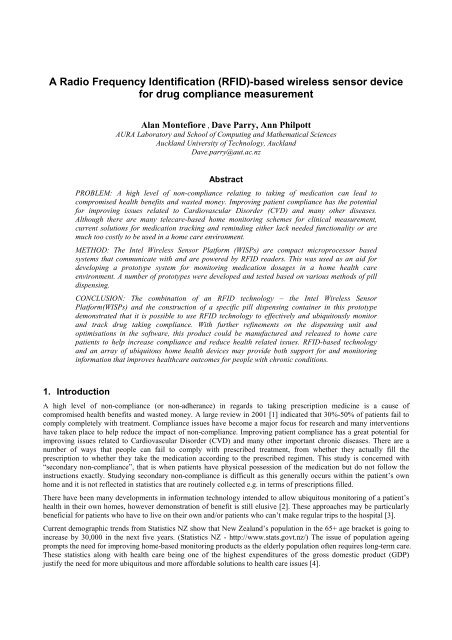
A <strong>Radio</strong> <strong>Frequency</strong> <strong>Identification</strong> (<strong>RFID</strong>)-based wireless sensor devicefor drug compliance measurementAlan Montefiore , Dave Parry, Ann PhilpottAURA Laboratory and School of Computing and Mathematical SciencesAuckland University of Technology, AucklandDave.parry@aut.ac.nzAbstractPROBLEM: A high level of non-compliance relating to taking of medication can lead tocompromised health benefits and wasted money. Improving patient compliance has the potentialfor improving issues related to Cardiovascular Disorder (CVD) and many other diseases.Although there are many telecare-based home monitoring schemes for clinical measurement,current solutions for medication tracking and reminding either lack needed functionality or aremuch too costly to be used in a home care environment.METHOD: The Intel Wireless Sensor Platform (WISPs) are compact microprocessor basedsystems that communicate with and are powered by <strong>RFID</strong> readers. This was used as an aid fordeveloping a prototype system for monitoring medication dosages in a home health careenvironment. A number of prototypes were developed and tested based on various methods of pilldispensing.CONCLUSION: The combination of an <strong>RFID</strong> technology – the Intel Wireless SensorPlatform(WISPs) and the construction of a specific pill dispensing container in this prototypedemonstrated that it is possible to use <strong>RFID</strong> technology to effectively and ubiquitously monitorand track drug taking compliance. With further refinements on the dispensing unit andoptimisations in the software, this product could be manufactured and released to home carepatients to help increase compliance and reduce health related issues. <strong>RFID</strong>-based technologyand an array of ubiquitous home health devices may provide both support for and monitoringinformation that improves healthcare outcomes for people with chronic conditions.1. IntroductionA high level of non-compliance (or non-adherance) in regards to taking prescription medicine is a cause ofcompromised health benefits and wasted money. A large review in 2001 [1] indicated that 30%-50% of patients fail tocomply completely with treatment. Compliance issues have become a major focus for research and many interventionshave taken place to help reduce the impact of non-compliance. Improving patient compliance has a great potential forimproving issues related to Cardiovascular Disorder (CVD) and many other important chronic diseases. There are anumber of ways that people can fail to comply with prescribed treatment, from whether they actually fill theprescription to whether they take the medication according to the prescribed regimen. This study is concerned with“secondary non-compliance”, that is when patients have physical possession of the medication but do not follow theinstructions exactly. Studying secondary non-compliance is difficult as this generally occurs within the patient’s ownhome and it is not reflected in statistics that are routinely collected e.g. in terms of prescriptions filled.There have been many developments in information technology intended to allow ubiquitous monitoring of a patient’shealth in their own homes, however demonstration of benefit is still elusive [2]. These approaches may be particularlybeneficial for patients who have to live on their own and/or patients who can’t make regular trips to the hospital [3].Current demographic trends from Statistics NZ show that <strong>New</strong> Zealand’s population in the 65+ age bracket is going toincrease by 30,000 in the next five years. (Statistics NZ - http://www.stats.govt.nz/) The issue of population ageingprompts the need for improving home-based monitoring products as the elderly population often requires long-term care.These statistics along with health care being one of the highest expenditures of the gross domestic product (GDP)justify the need for more ubiquitous and more affordable solutions to health care issues [4].
2. Enabling TechnologyThis section deals with some of the technology being used in the pilot device.2.1. <strong>RFID</strong> Technology<strong>Radio</strong> <strong>Frequency</strong> <strong>Identification</strong> (<strong>RFID</strong>) has become an integral part of our lives, in many application areas [5], perhapsthe most familiar being the “proximity access card”. <strong>RFID</strong> is a short-range radio technology that is best suited forcommunicating digital information about specific objects. In a typical scenario there are multiple <strong>RFID</strong>Tags/Transponders which are small and inexpensive and only one <strong>RFID</strong> Reader/Interrogator. Information can be sentfrom the tags by generating, modulating and transmitting a radio signal the reader can detect. A number of modulationtechniques can be used to enable read-only or read-write communication.The use of passive <strong>RFID</strong> tags provides many benefits. They are inexpensive, disposable, and durable. These benefitsallow the tags to be placed in many objects for gathering information for structural, medical and monitoring purposes.The major limitation of traditional Ultra High <strong>Frequency</strong> (UHF) tags is that they require a close proximity to a <strong>RFID</strong>reader to send data. This limits their functionality in scenarios such as supply chains or other applications where areader is not always present. A common alternative to passive tags are active tags which use a battery to enableprocessing of sensor data when away from the reader. This however introduces new issues such as battery lifespan,recharging capabilities and the use of hazardous chemicals such lithium, complicating disposal.2.2. Wireless <strong>Identification</strong> and Sensing Platform (WISP)WISP [6] is a new <strong>RFID</strong> tag technology that introduces a power model that is different to standard passive or active tags.WISPs are similar to passive tags in the sense that they only use power harvested from the reader’s RF signals, and likeactive tags they can continue collecting data away from readers. This ability is achieved by storing the harvested energyin a capacitor for later use. This is particularly useful for applications that have limited contact with readers. WISPshave been designed to run on the standardised EPC Gen 2 infrastructure. (www.epcglobalinc.org). This allows the useof commercially available readers that are compatible with EPC Gen 2 tags to collect tag data from the WISP (Figure 1).By allowing data capture and processing to continue while not within range of the reader, these tags are potentially anextremely flexible means of collecting summary data from the environment. The WISP has three in-built sensors -temperature, capacitance and a 3D accelerometer. Data from these sensors and a general purpose voltage sensor can beread when within range of an interrogator/reader via the normal EPC gen2 air interface, after loading a simple commandprogram into the WISP onboard memory.The reader used was an IMPINJ Speedway reader, a standard UHF Reader, connected to a PC via Ethernet. This readerhas a normal operational range of around 1 metre with a 30cm square antenna. As with many other readers, multipleantennae can be attached to a single reader.Figure 1. WISP mode of action
2.3. Prototype developmentThe prototype was designed to allow reliable recording of the number of pills dispensed from a container. The prototypepill counter was built based on the following requirements:• Each pill being dispensed would be detected, and movement of the container that did not result in a pill beingdispensed would not result in a false count• Because of limitations in the development environment for the WISP on-board computer, all data collection willoccurr within range of the <strong>RFID</strong> reader, with minimal on-board processing.• Pill dispensing should be based on a simple operation or set of operations.The rest of this section is divided into subsections dealing with the physical design of the pill container and the softwaredesign.2.3.1. Physical DesignThe development of a physical container is required to demonstrate the ability to dispense pills in such a way that it canbe monitored and tracked using the WISP technology. The 3D accelerometer sensor was used to detect movement in thecontainer whether it be a specific pattern or a difference in values from two or more WISPs. There was also thepossibility of using a combination of the sensors such as using the temperature sensor to detect a hand and the 3Daccelerometer to detect movement. The following sections will discuss the evaluation of a series of prototype containers.2.3.2. First ApproachThe first design approach aimed to produce a container that could detect dosages by recognising a specific movementusing one WISP tag. The aim was to require a ‘maze’ like movement before a pill was released such as ‘tilt down, thenup, then down’. This could be easily detected by the software. The initial approach was to construct an alternative lidthat had an inbuilt ‘maze’ trap as seen in Figure 2. The first noticeable flaw found when constructing this was it wouldbe difficult to ensure only one pill was released as the design was relying the corner to only allow one pill to go through.This design also had the capability of inconsistencies between actual pill count and what the software detected. If twopills managed to get into the second compartment in the ‘maze’ the software would not be able to detect it. Oneadvantage of this design if it could be engineered correctly would be that it be very easy to include a WISP chip anddevelop the software to detect the specific movement. However due to this simplicity it would also be prone to errors indetection when the container was just being shaken around, etc.Figure 2. Pill Container with ‘maze’ type lid
Figure 3. Pill container with catchmentThe second design was similar to the first design in regards to the detection of a specific movement; however the designof the pill dispensing mechanism was much more advanced and reliable. This design incorporated a catchment area thatcould only fit one pill. The sequence of how this idea works can be seen in Figure 3. The idea was that when thecontainer was turned on end all the pills would fall into the top section, then when turned back up-right they would allfall back apart from one which would be trapped in the catchment, then when inverted again the trapped pill would befree to fall out of the cap. The major problem with this design was the inability to construct it as precisely as needed forit to function correctly. Often the pills would not get trapped in the catchment, or more than one pill would escape whenthe container was inverted the second time. This design was again using the WISP tag to detect a specific movement(down, up, down).2.3.3. Second ApproachBoth these designs were unsatisfactory. However, another approach based on a lolly dispenser that had a more complexmechanism yet was still low cost seemed promising. We used the Smint ® dispenser as seen in Figure 4. This designcould not utilise a single WISP for movement. The incorporation of two WISP tags allows the application to detect differencesbetween their values, so when the button is pressed one of the WISPs rotates with respect to the other. The differencein values is detected by the system and if the difference is great enough it can be inferred that a pill was dispensed.The angle “noise” of the accelerometer is +/- 0.6 of a degree when stationary so the amount of rotation has to begreater than 2 degrees to reliably determine that the button was pushed. Any gross movement of the container will bepicked up by both WISPS and hence will be cancelled out in the processing phase.To achieve the ability to rotate the rotating WISP we built an internal mechanism that forces the WISP to rotate aroundthe point specified in Figure 5. The spring ensures the WISP locks back into place when the button is released; the bar isused for holding one side of the WISP up while the other drops. A second WISP tag is placed anywhere on the containerand calibrated to return the same values during gross movement of the whole devices as the rotating tag. Thisdesign can handle being dropped and shaken around as the detection is based on differences rather than individualmovements.Some considerations taken into account were isolating the sensors from elements that might affect reliability of resultsand distinguishing between actual dispensing of pills and general handling of the pill container.Figure 4. Smint ® dispenser.(http://www.foodengineeringmag.com/FE/2003/05/Files/Images/83059.jpg)
Figure 5. How the internal tilting mechanism works. (only one WISP shown for clarity)2.3.4. Software development ProcessThe software development was fairly simple involving modules to calibrate the two WISPs, a module to read the uniquetag IDs and record the angle as derived from the onboard sensors, and a calculation module to calculate the differencebetween the two angles and count pills dispensed. The “pills dispensed” algorithm is based on an angle difference ofmore than 6 degrees occurring, and then returning to less than this figure.3. ResultsFor testing the system as a whole (including container, static and dynamic tags, software and users) a number of taskswere used to ensure the system provided reliable results in all situations. The data collected from each test included atest number, software detected result (binary), actual result (binary), tilt value of static tag, tilt value of dynamic tag andthe tilt difference. When evaluating the results the software detected result and the actual result pair were studied to seehow closely the samples agree.The initial test was completed with a known number of pills using very deliberate movements when pushing the button.This was designed to test the functionality of the container and software when being used in ideal conditions. Each testwas performed separately with values being recorded after each press. Results are shown in Table 1 for:• Detected Result: Whether or not the software detected that a pill had been dispensed.• Actual Result: If a pill was dispensed from the device.• Tilt Static Chip: The tilt value returned from the WISP for the tag that does not move.• Tilt Dynamic Chip: The tilt value returned from the WISP for the tag that rotates when the button is pressed.• Difference Tilt: The difference between the tilt values. Used for determining if the button has been pushed.The second stage of testing the application and pill dispensing container was to get three people to use the devicewithout giving them direct instructions on how it works. They were instructed to dispense five pills (lollies) at a randominterval. The attempts from each user can be seen inTable 2.The results from the tests show that the software and container were performing as expected. With a 100% success indetection under general usage it can be seen that the device performs reliably. An interesting figure that was extractedfrom the test results was the mean of the tilt difference. Knowing the mean of the tilt difference allowed us to doublecheck that the values that were coded into the software were correct. With a mean tilt difference of 38, we wereconfident that the detection range (30-50) was accurate and would provide reliable results.
Table 1. Initial calibrationTest Detected Result Actual Result Tilt Static Chip Tilt Dynamic Chip Difference Tilt1 1 1 421 383 382 1 1 430 383 473 1 1 415 379 364 1 1 426 385 415 1 1 431 394 376 1 1 422 390 327 1 1 426 382 448 1 1 429 385 449 1 1 435 399 3610 1 1 431 387 44Table 2. Test user resultsTest Detected Result Actual Result Tilt Static Chip Tilt Dynamic Chip Difference Tilt11.1 1 1 424 386 3811.2 1 1 425 392 3311.3 1 1 424 378 4611.4 1 1 423 393 3011.5 1 1 427 387 4012.1 1 1 421 387 3412.2 1 1 418 387 3112.3 1 1 422 380 4212.4 1 1 419 381 3812.5 1 1 421 383 3813.1 1 1 381 346 3513.2 1 1 382 350 3213.3 1 1 381 349 3213.4 1 1 379 344 3513.5 1 1 385 342 43Table 3. Limits to dispensing angleTest Detected Result Actual Result Tilt Static Chip Tilt Dynamic Chip Difference Tilt14 1 1 437 407 3015 1 1 372 340 32
detection range of the <strong>RFID</strong> reader, this is a potentially very flexible device. Other sensors such as heat or lightdetection could also be used to gain a better understanding of the storage conditions of the drugs. Because the <strong>RFID</strong>detector is a standard type, this could also be integrated into a drug reminder/identification system [7], or systems thatmight be used for other sorts of homecare such as those designed to support the visually impaired. Cost of the systemdepends on the cost of WISPs which are not currently commercially available, as well as the <strong>RFID</strong> detector andassociated computer system. The <strong>RFID</strong> detector used (Impinj) is accessed via an Ethernet connection, so it is possiblethat wireless connection to this device could be established.These devices may become part of a “home healthcare hub” that would support both assisted living technology, and therecording of appropriate clinical data. Such systems are being advanced for particular user groups such as people withneurological impairment [8] By building devices that use common standards and that have low infrastructurerequirements, the acceptance of these devices is more likely. A comparison can be made with home entertainmenttechnology, where devices can be linked in a complex and expensive, but high performing system, “home theatre’, or asindividual items, or somewhere in-between. It may be that considering home telecare as a branch of consumerelectronics, rather than as the transplantation of hospital equipment, clinical transformation is more easily enabled.5. AcknowledgmentsThe authors would like to acknowledge the generous support of the INTEL WISP Challenge team and IMPINJ6. References[1] Vermeire E, et al., Patient adherence to treatment: three decades of research. A comprehensive review. J ClinPharm Ther, 2001. 26: p. 331 - 342.[2] Martin S, et al., Smart home technologies for health and social care support. Cochrane Database of SystematicReviews:, 2008. 2008(4).[3] Choi JM, et al. A System for Ubiquitous <strong>Health</strong> Monitoring in the Bedroom via a Bluetooth Network andWireless LAN. in Engineering in Medicine and Biology Society, 2004. IEMBS '04. 26th Annual InternationalConference of the IEEE. 2004.[4] Otto C, et al., System architecture of a wireless body area sensor network for ubiquitous health monitoring.Journal of Mobile Multimedia, , 2006. 1(4): p. 307-326.[5] Landt J, The history of <strong>RFID</strong>. Potentials, IEEE, 2005. 24(4): p. 8-11.[6] Sample AP, et al., Design of an <strong>RFID</strong>-Based Battery-Free Programmable Sensing Platform. Instrumentationand Measurement, IEEE Transactions on, 2008. 57(11): p. 2608-2615.[7] Houliston B, Merry A, and Parry DT, Sensors and Insensibility: Monitoring Anaesthetic Activity with <strong>RFID</strong>, in<strong>Health</strong> <strong>Informatics</strong> <strong>New</strong> Zealand Forum. 2008, HINZ: Rotorua.[8] Gentry T, Smart homes for people with neurological disability: State of the art. NeuroRehabilitation, 2009.25(3): p. 209-217.