Chapter one (Condensation and Boiling)
Chapter one (Condensation and Boiling)
Chapter one (Condensation and Boiling)
Create successful ePaper yourself
Turn your PDF publications into a flip-book with our unique Google optimized e-Paper software.
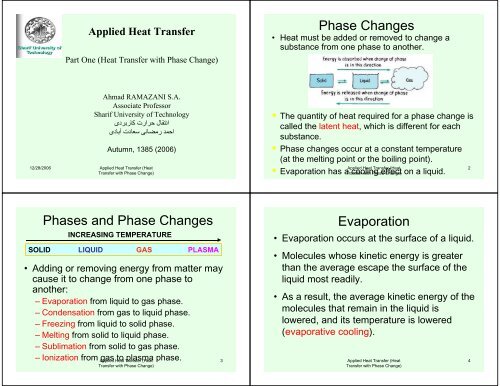
A problem about film condensationA problem about film condensationApplied Heat Transfer (HeatTransfer with Phase Change)29Applied Heat Transfer (HeatTransfer with Phase Change)30A problem about film condensationA problem about film condensationApplied Heat Transfer (HeatTransfer with Phase Change)31Applied Heat Transfer (HeatTransfer with Phase Change)32
A problem about film condensationA problem about film condensationApplied Heat Transfer (HeatTransfer with Phase Change)33Applied Heat Transfer (HeatTransfer with Phase Change)34Film condensation heat transfercoefficient on cylindersTurbulence Film condensation heattransfer coefficient on cylinders• Vertical Plates <strong>and</strong> Cylinders:The relation for average h on verticalplate can be also used for verticalcylinders surfaces with fluids with pr> o.5<strong>and</strong> cT /h fg< 1.0c= specific heat of liquidT g =T sat• Average Heat Transfer Coefficient onHorizontal Tubes (Nusselt relation)• For using this relation for n verticallytubes placed vertically its enough toreplace d with nd• For Isothermal Sphere its enough tochange coefficient from 0.725 to 0.815⎛ p(p − pv) ghfgkh = 0.943⎜⎝ Lµf( Tg−Tw)⎛ p(p − pv) gh kh = 0.725⎜⎝ µfd(Tg−Tw)3f3fg f1/ 4⎞⎟⎠1/ 4⎞⎟⎠Reynolds Number CalculationD pv 4ApvHRe = =fµ pµHA = flow areap = Shear, or "wetted," perimeterv = average velocity in flowconsideringWhere Γ = Mass flow per unit depth of plateFor verticall plate with unit width, pp = Π d ⇒ RefD = hydrauli diameterthatcriticalf≈1800.4m4Γm = pAv ⇒ Re = =fpµµ=.f1, <strong>and</strong> vertical tubesfApplied Heat Transfer (HeatTransfer with Phase Change)35Applied Heat Transfer (HeatTransfer with Phase Change)36
Reynolds Number relation with hReynolds Number Calculation−q = h A(Tsat−T) = m hfg4hL(Tsat−TW)⇒ Ref=h µW4Ah(Tsat−TW)Ref=h pµfgfffg.h A(T⇒ m =hPreviousely we have shown that : Re−For plate with A = LW <strong>and</strong> p = W−.−fsat−T)fg.W4m=pµfModified form of h for considering ripple (Wavymotion) effectsFor Reynolds more than 30 experiments show values that areabout 20 percent more than values that predict by formulathat we have obtained for average of h. So, McAdamschanged coefficient in the formula for h.3− ⎛ p(p − p ) ⎞vghfgkh = 1.13⎜⎟( )⎝ LµTg−Tw⎠1/ 4Applied Heat Transfer (HeatTransfer with Phase Change)37Applied Heat Transfer (HeatTransfer with Phase Change)38Calculation of h for inclined plate• If plate or cylinder has a angle of φ with thehorizontal, to use the previous formula it isenough to replaceg′= g sin Φg with g′− ⎛ p(p − p ) g sin Φhkvfgh = 0.943⎜⎝ Lµ( T −T)g w3⎞⎟⎠1/ 4The <strong>Condensation</strong> Number• Reynolds values can affect values of h, so it seems good torewrite h with Reynolds or an other dimensionless number.• For an inclined plates or cylinder from pervious results <strong>one</strong>can easily write;− 3/ 431/ 4− ⎛ p(p − p ) sin ⎞vg Φhfgkh = c⎜⎟( )⎝ µ L Tg−Tw⎠Balance of energy on film also gives"−mh &fgh A(T −T) = mh &g w fg⇒ Tg−Tw=−h AReplacingT−Tin h :hgw3⎛ p(p − p ) sin / ⎞vg ΦkA L= c⎜⎟⎝ µ m&⎠1/ 4Applied Heat Transfer (HeatTransfer with Phase Change)39Applied Heat Transfer (HeatTransfer with Phase Change)40
The <strong>Condensation</strong> Number (con.)• Solving the previous relation for h gives:1/ 33−⎛ p(p − p ) gkv µ A ⎞4 / 3p 4sin Φ / ph = c⎜µ m⎟2⎝4 &⎠We define the following, dimensionless group Cas "The <strong>Condensation</strong> Number":1/ 32− ⎛ µ ⎞C = h⎜⎟03k p p p g⎝ ( − )v ⎠So, Using two previous equations, C can be rewritten as :C = c0⎛ 4sin Φ A/p ⎞⎜⎟⎝ L ⎠4 / 3D pvhwhere Re =fµf1/ 3Re−1/3f00The <strong>Condensation</strong> Number (con.)• For Vertical plate A/PL=1 <strong>and</strong> so C 0 reduce to:C = 1.47 Refor Re p 1800For a horizontal Cylinder A/PL0for Re p 1800For turbulence condition experical correlation of Kirk - Bride ealtion can be used :00C = 1.51Re−1/ 3−1/34C = 0.0077 Reffffffor Re f 1800f= Π<strong>and</strong>Applied Heat Transfer (HeatTransfer with Phase Change)41Applied Heat Transfer (HeatTransfer with Phase Change)42Film <strong>Condensation</strong> inside horizontal tubes• Although it is important in so many application, as refrigeration<strong>and</strong> air-conditioning due to complexity of system there is notany analytical analysis for this type of heat transfer.• Chato present the following experimental relation forcondensation of refrigerants inside horizontal tubes1/ 43− ⎛ p(p − p ) gk h′⎞vfgdGvh = 0.555⎜⎟ for low vapor velocites, where Re = p 35000vµ d(T- T )⎝g w ⎠µvWhere G is mass flow of Vapor <strong>and</strong> its Reynolds Number must be evaluated at inletcondition to the tube.For high flow ratehkf= 0.026 prf1/3fRewheredGvAbove relation for Re = f 20000vµFor calculation of mass flow rate of0.8mrelation of Akers - Deans, <strong>and</strong> Crosser can be used;vRed pf= Mixture Reynolds Number = [ G + G ( )f vµ p]1/ 2mRevapor G <strong>and</strong> liquid Gvall areaApplied Heat Transfer (HeatTransfer with Phase Change)vdGf= f 5000µffhas about 50 percent accuracy.of tube must be consideredfv43Example 9-2. <strong>Condensation</strong> on Tube bank• One hundred tube of 0.5 in diameterare arranged horizontally in a squarearray <strong>and</strong> exposed to atmosphericsteam. Calculate the mass of steamcondensed per unit length of tubes fora tube wall temperature of 98 o C.Applied Heat Transfer (HeatTransfer with Phase Change)44
Example 9-2. <strong>Condensation</strong> on Tube bank (con.)The necessary formula for calculation h of <strong>one</strong> horizontal tube is presented already, for ntubes we can replace d with nd (where n=10 is the raw of tubes) in that formula.3⎛ p ( p − p ) gh k ⎞f f v fg fh = 0.725⎜⎟nd ( Tg T )⎝ µ −fw ⎠Fluid proprties must be calculated at film temperature100 + 98oT = = 98 Cf2−4µ = 2.82 × 10 kg / m.s2p ( p − p ) ≈ pTffsatfvo= 100 Cfhfg3p = 960 kg / mfok = 0.68W/ m.Cf1/= 2255KJ/ Kg4Example 9-2. <strong>Condensation</strong> on Tube bank (con.)We consider laminar flow <strong>and</strong> use formula obtained for <strong>one</strong> tube, but we replaced with nd where n=10 is number of tube in each vertical line263⎛ (960) (9.8)(2.255×10 )(0.68) ⎞h = 0.725⎜4(2.82 10 )(10)(0.0127)(100 98)⎟−⎝ ×− ⎠2 o2 o= 12540 W / m . C [2209 Btu/h.ft . C]The total surface area is :A2= nΠd= (100) Π(0.0127)= 3.99m/ mLq A(T −T)g WSo the heat transfer per length is = hL L= (12540)(3.99)(100 − 98) = 100.07KW/ mThe total mass flow of condensate is then5m&q / L 1.0007×10= =6L h 2.555×10fg= 0.0444Applied Heat Transfer (HeatTransfer with Phase Change)45Applied Heat Transfer (HeatTransfer with Phase Change)46<strong>Boiling</strong> Heat Transfer<strong>Boiling</strong> Heat TransferApplied Heat Transfer (HeatTransfer with Phase Change)47Applied Heat Transfer (HeatTransfer with Phase Change)48
<strong>Boiling</strong> Heat Transfer<strong>Boiling</strong> Heat TransferApplied Heat Transfer (HeatTransfer with Phase Change)49Applied Heat Transfer (HeatTransfer with Phase Change)50<strong>Boiling</strong> Heat Transfer<strong>Boiling</strong> Heat TransferP b -P =Applied Heat Transfer (HeatTransfer with Phase Change)51Applied Heat Transfer (HeatTransfer with Phase Change)52
<strong>Boiling</strong> Heat TransferBubble Size Change After Separation of<strong>Boiling</strong> Interface•Bubble Size dose not change if p b -p = ∆p= 2 σ/r•Bubble grows if p b increase•Bubble also grows if temperature of fluid is morethan vapor temperature (bubble temperature)•Bubble collapse if temperature of fluid is less thanvapor temperature (bubble temperature)Applied Heat Transfer (HeatTransfer with Phase Change)53Nucleate Pool <strong>Boiling</strong> Heat TransferExperimental Correlation of RohsenowhC ∆Tfglxsprl= Cs f⎛⎜q / A⎝µ lhfgg ⎞cσ⎟g(p − )l pv⎠0.33WhereC l =Specific heat of Saturated LiquidPr l = Pr<strong>and</strong>tl number of saturated liquid∆T x = temperature excess = T w -T satC sf = Constant, must be determined from experimental data, for waterplatinumcombination is 0.01, for other combinations see table 9-2Holman .S= 1.0 for water <strong>and</strong> 1.7 for other liquidsg c = Conversion factorApplied Heat Transfer (HeatTransfer with Phase Change)54<strong>Boiling</strong> Heat Transfer<strong>Boiling</strong> Heat TransferFig. 9-8.Heat Flux data for wateron a platinum wire, atdifferent pressuresFig. 9-9.Verification of Correlationfor pool-boiling atdifferent pressureApplied Heat Transfer (HeatTransfer with Phase Change)55Applied Heat Transfer (HeatTransfer with Phase Change)56
<strong>Boiling</strong> Heat TransferExample 9-3:<strong>Boiling</strong> on Brass Plate.A heated brass (67 percent copper <strong>and</strong> 33 percent zincalloy) is submerged in a container of water atatmosphere pressure. The plate temperature is 242 O F.Calculate the heat transfer per Unit area of Plate.Given information <strong>and</strong> data:<strong>Boiling</strong> heat transfer (water) on a brass plateT w= 242 O FT Sat= 212 o F , 100 o C (Atmospheric Pressure)Required: q/AApplied Heat Transfer (HeatTransfer with Phase Change)57Example 9-3. <strong>Boiling</strong> on Brass Plate (Con.)Solution:To solve this problem we can use directly Correlation of Rohsenow.hC ∆Tfglxsprl= Cs f⎛⎜q / A⎝µ lhfgg ⎞cσ⎟g(p − )l pv⎠This needs to put so many data in this relation <strong>and</strong> finally be solved it for q/A.0.33A more effective way is to write this relation for another system whose q/A can beEasily obtained from figures or tables such as Platinum-water at the same condition, <strong>and</strong>divide it with the system whose q/A must be calculated.( q / A)water − brassCsf water−platinium 3= ()( q / A)water − platinium Csf water−brassAt this way we only need to know q/A for water-platinum system <strong>and</strong> C fsof this system<strong>and</strong> water-Brass system.T w-T sat= 30 o FFigure 9-8 (q/A) water-platinum= 3*10^5 Btu/(h.ft 2 ) = 946.1 kW/m 2Applied Heat Transfer (Heat58Transfer with Phase Change)Table 9-2Example 9-3. <strong>Boiling</strong> on Brass Plate (Con.)( q / A)water − brassCs= (( q / A)water − platinium C(Cfs)water-brass= 0.0060(C fs) water-Platinium = 0.013f waterf water−brass(q/A) water-brass = (3* 10^5) (0.013/0.006)^3= 3.4 810^6 Btu/h.ft^2 = 1.072*10^7 w/m^2s− platinium)3Forced-Convection <strong>Boiling</strong> Heat Transfer•When a liquid moves forcibly on a surface whose temperatureis greater than saturation temperature of liquid, a forcedconvection boiling heat transfer happens.•In this case, total heat transfer can be consider as heattransferred by two mechanisms(q/A) total = (q/A) boiling + (q/A) forced convection•The above relation can be used when bulk liquid is insubcooled temperature (only local forced-convection boiling)Applied Heat Transfer (HeatTransfer with Phase Change)59•To calculate forced convection effects in smooth tubes <strong>one</strong> canuse relation of Dittus-Boelter (Eq. 6.4) with replacingcoefficient 0.023.by 0.019.Nu d = 0.019 (Re d ) 0.8 Pr 0.4Applied Heat Transfer (HeatTransfer with Phase Change)60
Forced-Convection <strong>Boiling</strong> Heat TransferFully developed nucleate boiling in tubes:•In this case effects of force convection reduce <strong>and</strong> heat fluxdose not depend on rate of convection•For low pressure MacAdams proposed the following relationq/A = 2.2539(∆T x ) 0.3.96for 0.2
The Peak <strong>Boiling</strong> Heat Flux on Horizontal Cylinder•Sun <strong>and</strong> Lienhard presented the following relation for thepeak boiling heat transfer on horizontal cylinder which is ingood agreement with experimental dataq′′max= 0.89 + 2.27exp( −3.44R′) for R′> 0.15q′′max Fwhere R′is ag(pl- pv)R′= R[ ]σ<strong>and</strong> q′′= is the peak heat flux on an infinite horizontal plate.q′′max Fmax F= 0.131dimensionless radius definied by :pvh [p -p ]fglv1/4Applied Heat Transfer (HeatTransfer with Phase Change)65Heat transfer coefficient in stable film-boilingon a horizontal tube•Bromley suggested the following relation for calculation of heat transfercoefficient in stable film-boiling region on a horizontal tube:3kgpv(pl− pv)g(hfg+ 0.4cpv∆Tx)1/ 4hb= 0.62[] ; d = tube diameterdµv∆Tx•The above relation only consider convection through film <strong>and</strong> does not consider theeffects of radiation. The total heat transfer coefficient may be calculated from theempirical relationhb1/3h = hb( ) + hrhwhere h is the radiation heat transfer coefficient <strong>and</strong> is calculatedby assumingσε ( −whr=T −Tσ = Stefan_boltzman Constant;Properties of the vapor in above<strong>and</strong> hfgrTw4Tsatan emissivity of4sat)(enthalpy of vaporization) is tounity for the liquid.Thus;ε = Emissivityrelationmust bebe evaluated at the saturation temperatureApplied Heat Transfer (HeatTransfer with Phase Change)surfaceevaluated at film temperature66Simplified Relation for <strong>Boiling</strong> Heat Transfer withWater•Some simplified relation for calculation of heat transfer coefficient on theoutside of submerged surface at atmospheric pressureSimplified Relation for <strong>Boiling</strong> Heat Transferoutside submerged surface at any pressure (Con.)•To consider influence of pressure, the calculated h at atmospheric pressurecan be modified by following relation;ph p= h1( ) p10.4Applied Heat Transfer (HeatTransfer with Phase Change)67•Where h p =Heat transfer coefficient at some pressure ph 1 =heat coefficient at atmospheric pressure as determined fromtable 9-3 (Previous table)p= system pressurep 1 = St<strong>and</strong>ard atmospheric pressureFor forced convection local boiling inside vertical tubes the followingrelation is recommended32 oh = 2.54( ∆T) exp( p /1.551) W/m . C; for 5 atm ≤ p ≤170 atmwher p = pressure∆Txxin MPa= temperature differenceApplied Heat Transfer (HeatTransfer with Phase Change)between surface<strong>and</strong> saturated liquid68
Example 9-4. Flow <strong>Boiling</strong> Inside TubeThe Heat Pipe•Water at 5 atm flows inside a tube of 1 in [2.54 cm] diameter under localboiling conditions where the tube wall temperature 10 o C above saturationtemperature. Estimate the heat transfer in a a 1.0 m length of tube (q/A).Given: <strong>Boiling</strong> flow inside tubewith ∆T x = 10 o CP= 5 atmRequirement: q/A=?Solution.We can used the last previous relation to solve this problem.A fixed-conductance heat pipe:It acts with only <strong>one</strong> condensing fluid <strong>and</strong> its thermalresistance is not a strong function of heat loadh = 2.54( ∆Tx)3exp( p /1.551)p= 5 (1.0132 * 10^5 N/M 2 ) =0.5066 MPah=2.54 (10 ^3)exp(0.5066/1.551)= 3521 W/m 2 . o CA=πdL= p(0.0254)(1.0)=0.0798m 2q= h A(T w -T sat ) = 3521 (0.0798) (10)= 2810 W/mApplied Heat Transfer (HeatTransfer with Phase Change)69Applied Heat Transfer (HeatTransfer with Phase Change)70The Heat PipeA Variable-conductance heat pipe:The gas in reservoir can change contact surface ofvapor with wick depend on vapor pressureApplications of The Heat pipeApplied Heat Transfer (HeatTransfer with Phase Change)71Applied Heat Transfer (HeatTransfer with Phase Change)72
Structure of The Heat PipeApplied Heat Transfer (HeatTransfer with Phase Change)73Example 9-6. Heat Flux Comparison•Using the data of table 9-4 (page 541 of Holman book), compare the axial heatflux in a heat pipe using water as the working fluid (at about 200 o C) with heatflux in a solid copper bar 8 cm long experiencing a temperature differential of100 o C.•Given information.Copper bar L= 8 cm∆T x = 100 o CRequirement: Comparison of q/A for heat pipe <strong>and</strong> a copper barSolution.q/A for copper road;From table A-2 K copper = 374 W/m.oCq/A = -k(∆T/∆x) = -(374) (-100)/0.08=467.5 kW/m 2 =0.04675kW/cm 2And q/A for heat pipe:Pipe heat working with water Table 9-4 (q/A) axial= 0.67 KW/cm 2q/A) heat pipe/( q/A) copper bar = 0.67/0.04675 =14.33Which show that why the heat pipe could have wide applicationsApplied Heat Transfer (HeatTransfer with Phase Change)74


