BrakeRite EHB & BrakeRite II - Titan
BrakeRite EHB & BrakeRite II - Titan
BrakeRite EHB & BrakeRite II - Titan

You also want an ePaper? Increase the reach of your titles
YUMPU automatically turns print PDFs into web optimized ePapers that Google loves.
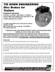
<strong>BrakeRite</strong> <strong>EHB</strong> &<strong>BrakeRite</strong> <strong>II</strong>ELECTRIC / HYDRAULICTOWED VEHICLE BRAKEACTUATION SYSTEMSINSTRUCTION ANDINSTALLATION MANUAL11/06
<strong>BrakeRite</strong> <strong>EHB</strong><strong>BrakeRite</strong> <strong>II</strong>TITAN TIRE CORPORATION2345 East Market StreetDes Moines, Iowa 50317800-832-8781www.titandist.com-i-
Section CONTENTS1.0 INTRODUCTION2.0 SAFETY CONCERNS & WARNINGS3.0 SYSTEM DESCRIPTION3.1 BRAKERITE <strong>EHB</strong>3.2 BRAKERITE VARIATIONS3.3 BRAKERITE <strong>II</strong>—SD3.4 BRAKERITE <strong>II</strong>—RF3.5 IN-CAB CONTROLLERS3.6 PRESSURE CONTROL3.7 BREAKAWAY4.0 ELECTRICAL4.1 REQUIREMENTS4.2 WIRING DIAGRAMS4.3 BREAKAWAY SWITCH4.4 BATTERY PROTECTION5.0 INSTALLATION5.1 MOUNTING LOCATION5.2 HYDRAULIC LINE5.3 ELECTRICAL CONNECTIONS5.3.1 BRAKERITE <strong>EHB</strong>5.3.2 BRAKERITE <strong>II</strong> SD5.3.3 BRAKERITE <strong>II</strong> RF5.4 SYSTEM START-UP5.4.1 ELECTRICAL CHECK5.4.2 FILLING THE RESERVOIR5.4.3 BLEEDING THE BRAKE LINES6.0 OPERATION6.1 COUPLING & UNCOUPLING THE TOWED VEHICLE6.2 UNIT OPERATION7.0 SERVICE & MAINTENANCE7.1 PERIODIC INSPECTIONS7.2 CHECK BEFORE EACH USE7.3 TROUBLESHOOTING7.4 REPLACEMENT PARTS8.0 WARRANTY9.0 DIAGRAMS / ILLUSTRATIONS-ii-
-1-1.0 - INTRODUCTIONCongratulations on your selection of a TITAN <strong>BrakeRite</strong> brake actuationsystem. TITAN has been a pioneer in the development of brake actuationand brakes. The <strong>Titan</strong> <strong>BrakeRite</strong> <strong>EHB</strong> & <strong>BrakeRite</strong> <strong>II</strong> Towed Vehicle BrakeActuation Systems are state of the art ELECTRIC over HYDRAULIC brakesystems.The systems use electric power from the towing vehicle to drive thehydraulic power source. In a breakaway situation the electric power issupplied by a breakaway battery connected to the Towed Vehicle BrakeActuation System. This battery is charged by a charger built into thecontrol circuitry. All <strong>BrakeRite</strong> systems are actuated one of three ways;primarily they turn on when the brake pedal of the towing vehicle isdepressed, if due to road conditions it is desirable to apply only thetowed vehicle brakes this is achieved by applying the manual over-rideon the “in-cab” brake controller, or in a breakaway situation the towedvehicle brake system is applied by the breakaway switch. Both “in-cab”over-ride and the breakaway feature are mandated by Federal Law.The <strong>BrakeRite</strong> <strong>EHB</strong> & <strong>BrakeRite</strong> <strong>II</strong> “SD” Towed Vehicle Brake ActuationSystems both require “in-cab” electric brake control not provide as a partof these two actuation systems. These two systems will operate from“most” electric brake controllers WHEN PROPERLY INSTALLED. The<strong>BrakeRite</strong> <strong>II</strong> “RF” Towed Vehicle Brake Actuation Systems has its own “incab”control.PROPER ELECTRICAL WIRING is CRITICAL for the performance of any ofthese systems. Improper wiring can result in damage to the actuationsystem or system failure after initial use. A “pure ground” and directpower (+12 VDC) with fuse or circuit breaker (30 amp) are necessary toensure good performance. Adequate wire size, 12 Gauge StrandedAutomotive or heavier is required, the longer the run the greater thechance of “line losses”. Line losses and poor grounding will result in poorperformance or total loss of towed vehicle braking! The use of “framegrounding” is not acceptable. Wiring for the <strong>BrakeRite</strong> <strong>EHB</strong> must be donein accordance with the wiring instructions provided. The connection forthe <strong>BrakeRite</strong> <strong>II</strong> “SD” & “RF” are provide by ‘pre-wired’ harnesses andthe plug connectors are “keyed” so that they cannot be connectedwrong, however, if the plug between towing and towed vehicles is notwired properly the unit will not function properly, or not at all. Consultapplicable wiring diagrams in section 9.0. Selection of a qualified andknowledgeable installer is key to years of trouble free service.
2.0 - SAFETY CONCERNSPROPER INSTALLATION & MAINTENANCE is essential for the safe andreliable operation of all vehicle braking systems. This manual provides ageneral outline of information addressing this matter. The variation in;tools, procedures, techniques, and related components related to theproper installation of these <strong>BrakeRite</strong> systems is as numerous as the skillsand knowledge of the individuals doing the installation. We cannot possiblyanticipate the various approaches or the possible effect of these variations.Therefore, anyone undertaking the installation and/or maintenance of any<strong>BrakeRite</strong> system must determine that the specific action taken will neithereffect personal safety nor effect the performance of the system or vehiclereliability by their approach, technique, and/or choice of relatedcomponents.BRAKE INSTALLATION, MAINTENANCE & REPAIR should be preformed onlyby qualified personnel, knowledgeable in braking and brake systems.WHEN COUPLING THE TOWED VEHICLE to the TOWING VEHICLE alwaysassure that the two vehicles are coupled in accordance with the vehiclemanufactures’ instructions and that ALL COUPLING DEVICES andPROCEEDURES CONFORM TO APPLICABLE STATE and FEDERALREGULATIONS.-2-
2.0 - SAFETY CONCERNS (cont.)Before using the trailer always check:1) PROPER BRAKE FLUID LEVEL:Must be between ⅜ & ¾ inch of filler opening.2) PRIOR TO MOVING THE COUPLED UNIT:a. Verify the brake system is working properly.(consult owners manual)b. Verify that Breakaway Protection is working properly,being certain Breakaway battery is properly charged.NEVER TRANSPORT THE TOWED VEHICLE if thebreakaway protection is not functioning properly.3) WHEN OPERATING/TRANSPORTING THE TOWED VEHICLE:a. Do not rely on the Towed Vehicle brakes fordeceleration of the entire combined unit braking. Thetowed vehicle Brakes are designed for braking of thetowed vehicle only and not the entire combined unit.b. Always operate the combined unit within the specifiedparameters outlined in the vehicle owner manuals andOBEY ALL LAWS.-3-
3.0 - SYSTEM DESCRIPTION3.1 The basic <strong>BrakeRite</strong> <strong>EHB</strong> & <strong>BrakeRite</strong> <strong>II</strong> units are the same, thedifference is with the electronics. The <strong>BrakeRite</strong> <strong>EHB</strong> has the ECB(electronic control board) built within the unit and has five wires exitingthe housing. Termination of the these five wires is performed by theinstaller per the wiring diagram. If not properly connected the unit willnot perform properly or at all. The <strong>BrakeRite</strong> <strong>II</strong> has no ECB and has athree-wire cable with a Female Weather Pack plug, therefore it requiresa control module. With the <strong>BrakeRite</strong> <strong>II</strong> either the SD or RF controlmodule is used (both systems described below).3.2 The heart of both the <strong>BrakeRite</strong> <strong>EHB</strong> & <strong>BrakeRite</strong> <strong>II</strong> are the electricmotor driven piston pump and electronically controlled pressure reliefvalve. The outward appearance of the two units are very similar, onlythe wiring exiting the housing is different and each has its own distinctModel Markings.3.3 The “SD” Control Kit for the <strong>BrakeRite</strong> <strong>II</strong> is basically the samecontrol circuitry as the <strong>BrakeRite</strong> <strong>EHB</strong>. However in an effort to improveinstallation efficiencies and reliability the “SD” control kit consists of;one SD Control Module, one I/O Harness with 7 pin RV plug 7 pin RVreceptacle and three wire tap with Weather Pack plug, one breakawayswitch with Weather Pack plug, and one battery cable with WeatherPack plug. All electrical circuitry is “plug-in”, the individual circuits arekeyed so that wires cannot be connected improperly. Great importancemust be placed upon proper wiring in the towing vehicle plug. (Consultthe wiring diagram in section 9.0).3.4 The “RF” Control Kit for the <strong>BrakeRite</strong> <strong>II</strong> is designed to make the<strong>BrakeRite</strong> <strong>II</strong> “RF” a ‘stand-alone’ brake actuation system. The systemrequires only a 4 pin flat connector between the towing and towedvehicles. Normal activation is achieved by the brake/signal light circuitand brake pressure is ‘modulated’ as a result of accelerometer outputin the control module. This system does not require a ‘hard wired incab’controller as it has its own controller.-4-
3.0 - SYSTEM DESCRIPTION (cont.)3.5 The ‘in-cab’ controller has a radio link between the control moduleand controller and a programmable code so that each controller willonly communicate with the specific control module intended. This ‘incab’controller plugs into the towing vehicle power source (cigarettelighter socket) and does not have to be ‘hard wired’ into the towingvehicle. The control module must be mounted facing forward andshould not be totally surrounded in metal. The “RF” Control Kit consistsof; one I/O Cable, Control Module, Breakaway Switch, and BatteryCable. All cables and module leads have Weather Pack plugs to insureproper connection.3.6 For the <strong>BrakeRite</strong> <strong>EHB</strong> & <strong>BrakeRite</strong> <strong>II</strong> SD the brake pressurecontrol is established by most in-cab electronic brake controllers andfor the <strong>BrakeRite</strong> <strong>II</strong> RF it has it’s own in-cab controller. Brakeperformance is selected by the driver, from the driver’s position and sois manual override if the drive wishes to apply only the towed vehiclebrakes.3.7 Federal law requires that ALL towed vehicles with brakes have theability to apply the brakes in the event that the towed vehicle becomesuncoupled from the towing vehicle. This requires a breakaway switchand a power source (battery) on the towed vehicle.The <strong>BrakeRite</strong> <strong>EHB</strong> & <strong>BrakeRite</strong> <strong>II</strong> control has circuitry for breakaway,however breakaway switches are provided only with the “SD” & “RF”control kits and no breakaway battery is supplied with any of the kits.-5-
4.0 - ELECTRICAL4.1 All models of the <strong>BrakeRite</strong> are 12 Volt DC with negative ground.Improper connections and grounding can and will result in damage tothe systems. For both the <strong>BrakeRite</strong> <strong>EHB</strong> & <strong>BrakeRite</strong> <strong>II</strong> SD 12 gauge orlarger wire must be run from the towing vehicle battery to the <strong>BrakeRite</strong>with either a 30 amp fuse or circuit breaker for protection. The controlleads for the <strong>BrakeRite</strong> <strong>EHB</strong> & <strong>BrakeRite</strong> <strong>II</strong> SD and all leads for the<strong>BrakeRite</strong> <strong>II</strong> RF 16 gauge or larger wires must be used. If light wiring isused for the power leads low voltages will result with slower responsetimes and generally poor performance of the brake system.For both the <strong>BrakeRite</strong> <strong>EHB</strong> & <strong>BrakeRite</strong> <strong>II</strong> SD a BREAKAWAY BATTERYOF AT LEAST 12 AMP HOURS must be used and for the <strong>BrakeRite</strong> <strong>II</strong> RFAT LEAST A 20 AMP HOUR BATTERY must be used. The breakawaybattery serves to operate both the <strong>BrakeRite</strong> <strong>EHB</strong> & <strong>BrakeRite</strong> <strong>II</strong> SD asa peaking battery for brake applications and to supply power in a“breakaway condition”. While for the <strong>BrakeRite</strong> <strong>II</strong> RF the battery notonly supplies power for “breakaway conditions” but also supplies thepower for operating the brake system. All three systems have internalchargers to maintain charge on the battery from the towing vehicle. Thecharger circuit for the <strong>BrakeRite</strong> <strong>II</strong> RF requires that the Running/Markerlights be on at ALL times during towing.4.2 Wiring Diagrams covering the <strong>BrakeRite</strong> <strong>EHB</strong>, <strong>BrakeRite</strong> SD &<strong>BrakeRite</strong> RF are provided on the pages indicated below:Pg. 19 <strong>BrakeRite</strong> <strong>EHB</strong> wiring diagram. (figure 4.2.1)Pg. 20 <strong>BrakeRite</strong> <strong>II</strong> SD wiring diagram. (figure 4.2.2)Pg. 21 <strong>BrakeRite</strong> <strong>II</strong> RF wiring diagram. (figure 4.3.3)-6-
4.0 - ELECTRICAL (cont.)4.3 The BREAKAWAY SWITCH (circuit) is required by law. Both of the<strong>BrakeRite</strong> <strong>II</strong> models have the switch included as part of the kit, howeverneither kit includes the battery. For the <strong>BrakeRite</strong> <strong>EHB</strong> neither the switchor battery is included and must be purchased separately. The switch,when installed properly, applies towed vehicle brakes in the event thatthe towed vehicle becomes un-coupled from the towing vehicle.The closing of a circuit is required to activate the breakaway function. Thebreakaway switch is a normally closed switch held OPEN by a plastic key.A cable is attached to the key and to the towing vehicle, if the unitsbecome uncoupled the cable pulls the key from the switch closing thecircuit activating the breakaway function and applying the trailer brakes.4.4 The ECB (electronic control board) has a battery protection circuit toassure that the breakaway (auxiliary) battery maintains a charge at alltime and prevents a surge charge witch could damage the battery. Thereis also protection designed into the board to prevent power draw from theauxiliary battery to the towing vehicle electrical system.-7-
5.0 - INSTALLATION5.1 Mounting location: Mounting the <strong>BrakeRite</strong> <strong>EHB</strong> or the <strong>BrakeRite</strong> <strong>II</strong> isat the discretion of the installer, however things such as accessibility forservice, protection from damage, and the ability to minimize the length ofhydraulic lines while protecting the integrity of the lines are factors to beconsidered. The physical envelope size for the power unit is approximately6 inches front to back, 7¼ inches left to right, and 9⅛ inches high. Twosets of mounting holes are provided in the power unit; one set is located inthe bottom (Figure 5.1A—pg.22) consisting of four ¼-20 UNC x ⅝ deepand one set located in the back (Figure 5.1B—pg.22) consisting of three5/16-18 UNC x ⅝ deep.SEE MOUNTING TEMPLATE INSERT FOR HOLE PATTERN5.2 Hydraulic Line: All <strong>BrakeRite</strong>s have a ⅛-27 NPTF port located on thelower front of the housing and a straight ⅛-27 NPTF Male by #3 FemaleInverted Tube seat (¾-24 NPTF) adapter. When installing this or anyadapter do not use TEFLON PIPE TAPE, properly mated brass fitting jointsdo not require a sealant. Route the brake lines to the axels per the BrakeLine Fitting Kit manufactures instructions, using flexible tubing as requiredand properly securing all tubing and hoses for maximum protection fromdamage due to pinching, vibration, corrosion, or catching on road hazards.When bending and flaring steel tubing always use the proper tools toassure sound connections to prevent “kinking the lines. Kinked and /ordamaged brake lines can cause restriction in flow resulting in poor brakingor no brakes at all.5.3 Electrical Connections: Depending upon the brake system chosenthere are various approaches to be considered. Though TITAN is theproducer of the <strong>BrakeRite</strong> <strong>EHB</strong> system and the two <strong>BrakeRite</strong> <strong>II</strong> systems<strong>Titan</strong> has NO control over how the towing vehicle or the basic wiring on thetowed vehicle have been installed or its color coding. Therefore, wheninstalling any of the <strong>BrakeRite</strong> systems it is important that all wiring isconnected per these instructions. While it is desirable to establish aground between the frame, <strong>BrakeRite</strong> unit, and also the negative side ofthe breakaway battery, NEVER RELY SOLELY ON FRAME GROUNDING.-8-
5.0 - INSTALLATION (cont.)Always use good ground leads between ALL specified points. As theelectrical potion of the installation is carried out make certain the wiresare properly routed, wrapped, anchored, and protected to preventdamage or catching on road hazards. When making connection in thecircuit, other than the plug-in connectors, the desirable joint is a solderjoint. If using crimp-type joints always use the manufacturersrecommended crimping tools in accordance with the manufacturersdirections and always properly wrap and protect all joints to prevent“shorting” and corrosion.5.3.1 The <strong>BrakeRite</strong> <strong>EHB</strong> requires that the installer assure that allwires are connected properly, per the applicable wiring diagram,insuring that the system works as designed. FIGURE 4.2.1 (pg.19) isthe preferred method for electrical wiring, this method requires anindependent battery solely for the brake system. However, the towedvehicle auxiliary battery can be used in place of the breakaway batteryif it is in good condition and fully charged. NOTE: If the towed vehiclehas set for an extended period of time the auxiliary battery may havebeen discharge excessively resulting in poor or no braking.5.3.1.1 Function of and size of each of the five (5) wires exiting the<strong>BrakeRite</strong> <strong>EHB</strong> unit are as follows:5.3.1.1.1 White 12 gauge, 12 VDC negative (-) system ground.5.3.1.1.2 Black 12 gauge, 12 VDC Positive (+) systempower in.5.3.1.1.3 Blue 18 gauge, Brake Control Input (from In CabElectronic Brake Controller)5.3.1.1.4 Brown 14 gauge, Breakaway Input (from one lead ofBreakaway switch)5.3.1.1.5 Violet (mauve) 14 gauge, 12 VDC Input/Outputbetween Unit and Breakaway battery. (2 nd lead ofBreakaway switch is also connected to 12 VDCpositive of breakaway battery)-9-
5.0 - INSTALLATION (cont.)5.3.2 The <strong>BrakeRite</strong> <strong>II</strong> SD kit has a complete wiring harness as a“plug-in” system and all connections within the system have been“pre-selected” at the factory so that upon installation the connectorsare simply plugged in. Though TITAN is the producer of the <strong>BrakeRite</strong><strong>II</strong> SD system, <strong>Titan</strong> has NO control over how the towing vehicle or thebasic wiring on the towed vehicle have been installed or its colorcoding. It is crucial that the SEVEN PIN “RV” receptacle on the towedvehicle is wired per FIGURE 5.3.2A (pg.23—is the most commonfactory installed wiring arrangement). The two basic options left tothe installer are whether to use the auxiliary battery on the towedvehicle, if one is available, or to install a separate breakaway battery(the preferred method). No battery is supplied with the kit. FIGURE4.2.2 (pg.20) illustrates the preferred method (separate breakawaybattery) however, the towed vehicle auxiliary battery can be used inplace of the breakaway battery if it is in good condition and fullycharged.5.3.3 The <strong>BrakeRite</strong> <strong>II</strong> RF kit is supplied complete with the wiringharness as a “plug-in” system so that all connections within thesystem have been “pre-selected” at the factory, upon installation theconnectors are simply plugged in. Though TITAN is the producer ofthe <strong>BrakeRite</strong> <strong>II</strong> RF system, <strong>Titan</strong> has NO control over how the towingvehicle or the basic wiring on the towed vehicle have been installedor its color coding. The Four Pin Flat Connector on the towing vehiclemust be wired as shown in FIGURE 5.3.3A (pg.24—this is theindustry excepted standard). As with The <strong>BrakeRite</strong> <strong>II</strong> SD two basicoptions left to the installer are whether to use the auxiliary battery onthe towed vehicle, if one is available, or to install a separatebreakaway battery (the preferred method). No battery is suppliedwith the kit. FIGURE 4.2.3 (pg.21) illustrates the preferred method(separate breakaway battery) however, the towed vehicle auxiliarybattery can be used in place of the breakaway battery if it is in goodcondition and fully charged.-10-
5.0 - INSTALLATION (cont.)5.4 System Start-Up: After the unit has been mounted, all hydraulic lineshave been installed and connected, and the electrical connections havebeen completed we can now proceed with the start-up of the system.5.4.1 Initial electrical check: Before putting brake fluid into the unitpull the Breakaway switch to insure that the unit starts and runs.Do not allow the unit to run more the ten (10) seconds. Aftertesting the breakaway feature test the manual override feature andalso depress the brake pedal to assure that this will start the unit.At no time during these initial checks should the unit be allowed torun dry for more then five (5) consecutive seconds.5.4.2 Fill reservoir and Bleed the brakes: Upon initial verification ofthe electrical system remove one of the filler caps and fill thereservoir to within 3/8 inches of the filler cap opening (there aretwo filler caps on the reservoir, either may be used for filling andchecking fluid level as they both enter a common reservoir) seeFIGURE 5.4.2A (pg.22). Fill the reservoir with NEW DOT <strong>II</strong> BRAKEFLUID. Never reuse brake fluid that has been salvaged or removedfrom another system. Contaminated or dirty brake fluid may causedamage to the system resulting in system failure.5.4.2.1 Bleeding the brakes: It is essential to remove all air fromthe brakes and brake-lines prior to operation of the vehicle. Tobleed the brakes remove the key from the breakaway switch tostart the unit. Starting with the brake furthest from the actuatoropen the ‘bleeder screw’ and allow it to remain open untilseeing brake fluid free of air bubbles coming out of the bleederscrew. Close the bleeder screw and move to the next brake andso on until all brakes have been bled. While performing thebleeding process monitor the fluid level in the reservoir so thatmore air is not pumped into the brake lines because of low fluidlevel. To prevent spilling brake fluid on the ground one end of alength of plastic tubing should be placed over the end of thebleeder screw and the other end should be placed into acontainer (see FIGURE 5.4.2.1A—pg.24) so that the fluid flowcan be monitored for bubbles. After all brakes have been bledreplace the “key” in the breakaway switch.-11-
6.0 - OPERATION6.1 Coupling the Units: WHEN COUPLING THE TOWED VEHICLE to theTOWING VEHICLE always assure that the two vehicles are coupled inaccordance with the vehicle manufactures’ instructions and that ALLCOUPLING DEVICES and PROCEEDURES CONFORM TO APPLICABLESTATE and FEDERAL REGULATIONS.6.1.1 Install Electrical Plug: After the units are properly coupledconnect the electrical plug and assure that the “safety cable”from the breakaway switch on the towed vehicle is connected tothe towing vehicle.6.1.1.1 Test Prior to Moving the Vehicle: To assure properconnections have been made, most In-Cab controllers havesome type of indicator to show that the electricalconnection is adequate. Consult the “In-Cab Controller”manufacturers operator’s manual for proper checking andsetting procedures. Before moving the vehicle depress thetowing vehicle brake pedal, the <strong>BrakeRite</strong> unit should start(you can hear the unit running). Release the towing vehiclebrake pedal and activate the <strong>BrakeRite</strong> unit by operatingthe “manual override” on the “In-Cab” controller, again youwill hear the unit turn on. With the manual override you areable to tell by the change in tone that the system isbuilding pressure relative to the amount of “activation”initiated on the override switch (again consult the In-CabController Manual for proper operation). Do Not attempt tomove the unit until the brake system performs in the testsdescribed above!-12-
6.0 - OPERATION (cont.)6.1.1.2 Getting the feel of the system and setting the In-Cab controller: After the system responds to the testspreviously described you may proceed with moving thevehicle to establish feel for the brake system and also to setyour brake response based upon the instructions given inthe Electronic Brake Controller manual. It is best to performthis familiarization in a parking lot or low traffic area. Do Notattempt to operate this unit in congested traffic or on majorthough fares until you have totally familiarized yourself withthe “feel” and performance of the system. Every operatorand every vehicle have unique requirements andcharacteristics. Take the time to familiarize yourself withthe feel of the unit, the performance of the brake system,and the proper operation and setting selections of theElectronic Brake Controller.6.2 Operation: Towed vehicle brakes are meant to assist the towingvehicle in the stopping of the combined units, they are not intended tostop the entire combined unit. There are two basic types of “In-Cab”Electronic Brake Controllers; one is the inertia based controllers thatcreate a small ‘bias’ braking force when activated and modulates thebraking forces of the towed vehicle relative to the braking “reaction”created by the towing vehicle, these offer the most desirable brakingeffect. The second type of In-Cab Electronic Brake Control is time basedcontroller. This type of controller turns on when the towing vehiclebrake pedal is applied and braking force increases at a selected rate ofincrease until it reaches maximum set point. This does not generate assmooth of braking as the inertia based controller and is very speedsensitive. No matter what type of controller you have thoroughly knowits performance and “feel” before any extensive travel is considered.Manual override is required by law and should be fully understood forsafe operation. When operating on wet or slippery surfaces it isdesirable to brake only with the towed vehicle brakes to maintainalignment of the vehicles and help prevent a jack-knife condition. Bymaintain adequate braking on the towed vehicle, sway or the tendencyof the towed vehicle to “push” the towing vehicle is greatly reduced.-13-
7.0 - SERVICE & MAINTENANCE7.1 Periodic Inspection should be made of the electrical connecter,wiring, brake lines and hose for the entire brake system to insure thereare no abraded or bare wires, damaged steel lines, or cracked anddamaged hoses. During inspection assure there are no loose or“hanging” lines or wire that might drag or catch on objects/debris whilebeing towed.7.2 Every time the towed vehicle is coupled to a towing vehicle:7.2.1 Check the fluid level in the reservoir. The fluid level must bemaintained within ⅜ to ½ inch below the filler opening. If brakefluid is needed add only NEW, CLEAN, DOT <strong>II</strong>I BRAKE FLUID. Usecaution when opening to the reservoir (removing the filler cap) toprevent the admission of dirt and/or contaminants into the fluidreservoir.7.2.2 Check to be certain the breakaway battery is charged and thatthe breakaway works. This is accomplished by “pulling” the cable onthe breakaway switch. If the vehicle has been parked for long periodsof time the breakaway battery may be discharged. If this is thesituation, charge the breakaway battery per manufacturersrecommendations prior to using the vehicle. If the battery is allowedto discharge in a cold environment there is a possibility of freezing it,causing damage to the battery.7.2.3 Inspect the coupler and safety chains to assure that they arefully functional and there is no wear or damage to them and that theymeet manufacturers specifications and recommendations and allapplicable state and federal laws.-14-
7.0 - SERVICE & MAINTENANCE (cont.)7.3 Trouble ShootingISSUEIndicator on “In Cab Controller”Shows no connection betweentowed and towing-vehicleSOLUTIONInspect plug and wiring foropen circuit. Consult applicablewiring diagram to assure properwiring connectionsPoor response timeCheck and add brake fluid asrequired (figure 5.4.2A-pg.22)Bleed brake lines and devicesCheck input for adequate “charge”(12 VDC)Inadequate or excessive trailerbrakingAdjust “gain” control on In-CabController<strong>BrakeRite</strong> unit runs but does notbuild pressureAssure proper brake fluid level, addfluid and bleed the system asrequired<strong>BrakeRite</strong> unit does not run whenBreakaway is pulledCheck breakaway battery charge.Assure wires are properlyconnected.<strong>BrakeRite</strong> unit does not run when Verify and connect wire connectionsthe vehicle brake pedal is depressed in the entire electrical circuit<strong>BrakeRite</strong> unit does not run whenthe in-cab manual override isactivated.Verify and connect wire connectionsin the entire electrical circuitExperience has shown that virtually all problems with <strong>BrakeRite</strong> units arethe result of INCORRECT OR FAILED WIRING. If problems arise consult theapplicable wiring diagram (Section 9.0) and inspect all wiring andterminations.-15-
7.0 - SERVICE & MAINTENANCE (cont.)7.4 Replacement Parts:7.4.1 <strong>BrakeRite</strong> <strong>EHB</strong> is shipped from the factory with “tamperproof” seals between the cover and casting. The warranty is voidif these seals have been broken. Contact <strong>Titan</strong> Distribution, Inc.at 800-832-8781 for information on where to obtain relatedservice parts such as; breakaway switches, breakaway batteries,electrical plugs, filler caps.For <strong>BrakeRite</strong> <strong>EHB</strong> unit covered by warranty, requiring repairs,follow the instructions on page 18, section 8.5.If the <strong>BrakeRite</strong> <strong>EHB</strong> is out of warranty contact <strong>Titan</strong> Distribution,Inc. at 800-832-8781 for a service center and parts source.7.4.2 <strong>BrakeRite</strong> <strong>II</strong> SD & <strong>BrakeRite</strong> <strong>II</strong> RF have various partsavailable as service parts. Consult the applicable illustration forservice parts and contact <strong>Titan</strong> Distribution, Inc. at800-832-8781 for information on where to obtain these serviceparts.-16-
8.0 - WARRANTY8.1 - Eligibility. You are eligible for the benefits of this limited warrantyif you are the original end-use purchaser of this <strong>BrakeRite</strong> <strong>EHB</strong> and ifthe unit has been used only on the vehicle in which it was firstinstalled.8.2 - What Is Covered. <strong>Titan</strong> Tire warrants this product to be free fromdefects in material and workmanship for 18 months after the date ofmanufacture or one year from the date of retail sale, whichever occursfirst, when properly installed, used and maintained.8.3 - What Is Not Covered. The warranty does not apply to damage orloss caused by any of the following circumstances or conditions:1. Freight damage2. Misapplication, misuse, modification, or failure to follow thedirections or observe cautions and warnings on installation,wiring, operation, application, inspection or maintenancespecified in any <strong>Titan</strong> specification sheet, instruction andinstallation manual ;3. Using parts, accessories or components not specified in<strong>Titan</strong>’s specification sheet, instruction and installationmanual or approved by <strong>Titan</strong> Tire in writing.8.4 - Conditions and Limitations. <strong>Titan</strong> Tire’s liability and purchaser’sremedy are expressly limited, at <strong>Titan</strong>’s sole option, to the repair orreplacement of the defective product.For the warranty to apply, <strong>Titan</strong> Tire must receive notice of the allegeddefect within 30 days of i) the alleged defect or ii) the expiration ofthe warranty period, whichever is earlier. Any claim not made withinthis period shall conclusively be deemed void.<strong>Titan</strong> Tire reserves the right to request that the product be returned to<strong>Titan</strong> Tire, intact and postage prepaid, prior to processing a warrantyclaim.-17-
8.0 - WARRANTY<strong>Titan</strong> Tire shall not be liable for loss of use of the unit, or any otherincidental or consequential costs, expenses or damages incurred bythe purchaser.Some states do not allow the exclusion or limitation of impliedwarranties, incidental or consequential damages, so the abovelimitations or exclusions may not apply to you.This warranty gives you specific legal rights. You may also have otherrights which vary from state to state.8.5 - To Receive Benefits Under This Warranty.Contact <strong>Titan</strong> Tire at the address or phone number below to obtain anauthorization for return.<strong>Titan</strong> Tire CorporationAttention Warranty Dept.2345 E. Market StreetDes Moines, IA 50317800-832-8781The product must be returned, shipping costs prepaid, insured to thefactory for evaluation.The following information should be available when contacting thefactory and must accompany the return, legibly prepared: i) name,address and telephone number of purchaser, ii) proof of purchaseincluding date, iii) model and serial number of the unit, iv) name andaddress of the dealer where the unit was purchased, v) description ofthe alleged defect.These terms and conditions represent the entire <strong>Titan</strong> Tire <strong>BrakeRite</strong><strong>EHB</strong> warranty, and no terms or conditions in any way adding to,modifying or otherwise altering the provisions stated herein shall bind<strong>Titan</strong> Tire unless in writing signed by <strong>Titan</strong> Tire.-18-
-19-9.0 - DIAGRAMS / ILLUSTRATIONS
9.0 - DIAGRAMS / ILLUSTRATIONS-20-
-21-9.0 - DIAGRAMS / ILLUSTRATIONS
9.0 - DIAGRAMS / ILLUSTRATIONSFIGURE 5.1A FIGURE 5.1BBRAKERITE <strong>EHB</strong> & BRAKERITE <strong>II</strong>FILLER CAPFILLER CAPFIGURE 5.4.2ABRAKERITE <strong>EHB</strong> & BRAKERITE <strong>II</strong>-22-
-23-9.0 - DIAGRAMS / ILLUSTRATIONS
9.0 - DIAGRAMS / ILLUSTRATIONSCar/Truck ConnectorTrailer ConnectorFigure 5.3.3AFour Pin Flat Connector - <strong>BrakeRite</strong> <strong>II</strong> RF ConnectionWhite Wire - Vehicle GroundBrown Wire - Vehicle Running LightsYellow Wire - Left Turn and Left Brake LightGreen Wire - Right Turn and Right Brake LightFigure 5.4.2.1ABleeder Screw & Tube-24-
IMPORTANT SAFETY NOTICEAppropriate installation, maintenance, and repair procedures areessential for the safe, reliable operation of vehicle brakes, as wellas the safety of the individual doing the work. This bookletprovides general information in this regard.There are numerous variations in procedures, techniques, tools,and parts for servicing brakes, as well as in the skill of theindividual doing the work. This booklet cannot possibly anticipateall such variations and provide advice and caution as to each.Accordingly, anyone who undertakes to install, maintain, or repaira vehicle brake system or brake system components, must firstestablish that they neither compromise their personal safety northe vehicle integrity by their choice of methods, tools or parts.TITAN TIRE CORPORATION2345 East Market StreetDes Moines, Iowa 50317800-832-8781www.titandist.com