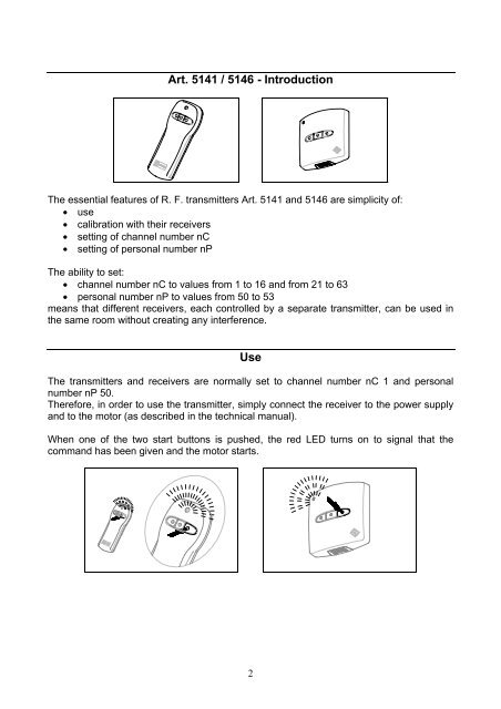
Art. 5141 / 5146 - Introduction Use - Weba
Art. 5141 / 5146 - Introduction Use - Weba
Art. 5141 / 5146 - Introduction Use - Weba

Create successful ePaper yourself
Turn your PDF publications into a flip-book with our unique Google optimized e-Paper software.
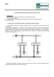
Channel number nC and personal number nP of the transmitter are defined by setting aDip Switch.ON1 2 3 4 5 6 7 8DefaultFactory setting:Channel number nC = 1Personal number nP = 50Each of the first 6 pins on the Dip Switch is assigned a value (in an arithmetic progressionwith common difference of 2). The numerical sum of the values defined by the pins set toON represents channel number nC.ON1 2 3 4 5 6 7 8nC = 1nC = 2nC = 4nC = 8nC = 16nC = 32nPA transmitter set to channel number nC 20 lets you give a “universal” group command.All of the receivers respond to pulses defined by channel number nC 20, in addition tothose for which they were calibrated.4
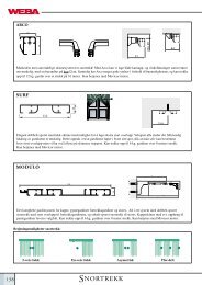
3. Set the receiver in calibration mode by pushing the button shown in the figure (ifnecessary, consult the technical manual).Power 491Old<strong>Art</strong>. 5132 - 5133 - 5136<strong>Art</strong>. 5315New<strong>Art</strong>. 5135Mono 373Rotary 449 - 445<strong>Art</strong>. 53154. The yellow LED will start flashing to indicate entry in calibration mode.6
5. Push the calibration button for about 1-2 seconds: the red LED will turn on.ON1 2 3 4 5 6 7 86. Check that the yellow LED on the receiver is still flashing. Push one of the startbuttons for about 2-3 seconds: the red LED on the transmitter will turn off.7. The yellow LED on the receiver will turn off to confirm calibration.8. Close the transmitter cover.7
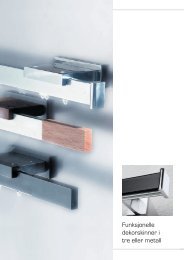
<strong>Art</strong>. 5142 / 5147 - <strong>Introduction</strong>The essential features of R. F. transmitters <strong>Art</strong>. 5142 and 5147 are simplicity of:• use• calibration with their receivers• setting of channel numbers nC• setting of personal number nPWith R. F. transmitters <strong>Art</strong>. 5142 and 5147, you can separately control two receivers set tochannel numbers nC in sequence and to the same personal number nP.The ability to set:• channel number nC to values from 1 to 16 and from 21 to 63• personal number nP to values from 50 to 53means that different receivers, each controlled by a separate transmitter, can be used inthe same room without creating any interference.<strong>Use</strong>Normally, the first set of buttons on the transmitter and receivers are set to channelnumber nC 1 and to personal number nP 50. The second set of buttons on thetransmitter is therefore set to channel number nC 2.By connecting the receivers to the power supply and to the motors (as described in thetechnical manuals), and pushing one of the two start buttons in the first set of buttons,the red LED turns on to signal that the command has been given and all the motors start.8
The motors generally stop when the end of travel position is reached, but can also bestopped with the transmitter by pushing the stop button.Or by pushing the button opposite the one that turned on the system.To use the second set of buttons, you have to calibrate one or more receivers.Calibrating and settingchannel number nC / personal number nPIf the motors don’t start after the transmitter has sent a command, or if you want to use thesecond set of buttons, calibration is necessary. With this simple procedure, channelnumbers nC and personal numbers nP on the receivers are set to the same values asthose of the transmitter.1. Remove the transmitter cover.9
Channel number nC and personal number nP of the transmitter are defined by setting aDip Switch.Each of the first 6 pins on the Dip Switch is assigned a value (in an arithmetic progressionwith common difference of 2). The numerical sum of the values defined by the pins set toON represents channel number nC for the first set of buttons.Channel number nC for the second set of buttons is the number immediately followingthat for the first set of buttons (it cannot be changed individually).See pages 4-5 for details.2. Set the channel number nC and personal number nP that you want.ON1 2 3 4 5 6 7 812345678ON3. Set the receiver to be controlled by the first set of buttons of the transmitter incalibration mode. See page 6 and consult the technical manual if necessary.4. The yellow LED will start flashing to indicate entry in calibration mode.5. Push the calibration button for about 1-2 seconds: the red LED will turn on.ON1 2 3 4 5 6 7 810
6. Check that the yellow LED on the receiver to be controlled by the first set ofbuttons is still flashing. Push one of the start buttons in the first set of buttons forabout 2-3 seconds: the red LED on the transmitter will turn off.7. The yellow LED on the receiver will turn off to confirm calibration.8. Set the receiver to be controlled by the second set of buttons of the transmitter incalibration mode by pushing the button shown in the figure. See page 6 and consultthe technical manual if necessary.9. The yellow LED will start flashing to indicate entry in calibration mode.10. Push the calibration button for about 1-2 seconds: the red LED will turn on.ON1 2 3 4 5 6 7 811. Check that the yellow LED on the receiver to be controlled by the second set ofbuttons is still flashing. Push one of the start buttons in the second set of buttonsfor about 2-3 seconds: the red LED on the transmitter will turn off.11
Calibrating and settingchannel number nC / personal number nPIf the motors don’t start after the transmitter has sent a command, or if you want to use theother sets of buttons, calibration is necessary. With this simple procedure, channelnumbers nC and personal numbers nP on the receivers are set to the same values asthose of the transmitter.1. Remove the transmitter cover.Channel number nC and personal number nP of the transmitter are defined by setting aDip Switch.Each of the first 6 pins on the Dip Switch is assigned a value (in an arithmetic progressionwith common difference of 2). The numerical sum of the values defined by the pins set toON represents channel number nC for the first set of buttons.Channel number nC for the second set of buttons is the number immediately followingthat for the first set of buttons (it cannot be changed individually).Channel number nC for the third set of buttons is the number immediately following thatfor the second set of buttons (it cannot be changed individually).Channel number nC for the fourth set of buttons is the number immediately followingthat for the third set of buttons (it cannot be changed individually).See pages 4-5 for details.2. Set the channel number nC and personal number nP that you want.ON1 2 3 4 5 6 7 812345678ON3. Set the receiver to be controlled by the first set of buttons of the transmitter incalibration mode. See page 6 and consult the technical manual if necessary.14