Anritsu MS2661C: Microwave Spectrum Analyzer - elsinco
Anritsu MS2661C: Microwave Spectrum Analyzer - elsinco
Anritsu MS2661C: Microwave Spectrum Analyzer - elsinco

You also want an ePaper? Increase the reach of your titles
YUMPU automatically turns print PDFs into web optimized ePapers that Google loves.
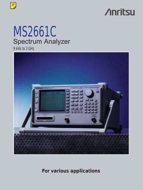
<strong>MS2661C</strong><strong>Spectrum</strong> <strong>Analyzer</strong>9 kHz to 3 GHzFor various applications
Portable at Only 11 kgIn the latest radio communications systems, the developmentof improved frequency efficiency and sophisticateddigital functions are emphasized. The <strong>MS2661C</strong> portablespectrum analyzer is ideal for analyzing the signals ofabove systems, device and related equipment.The <strong>MS2661C</strong> is a fully synthesized spectrum analyzer coveringa wide frequency range from 9 kHz to 3 GHz. And the<strong>MS2661C</strong> has superior basic performance such as highC/N ratio, low distortion, and high frequency/level accuraciesand is easy to operate. In addition, a Gaussian filter isused as a resolution bandwidth filter. The large selection ofoptions is available to handle a wide range of applicationscan be handled at reasonable cost.■ Compact and lightweight(11 kg in standard configuration)●Easy portability for installation and maintenance■ High C/N and superior distortion characteristics● Measurement speed improved by using 100 dB logdynamic range■ Easy-to-use, simple operation●Built-in “Measure” function for evaluation of radio equipment(Frequency counter, C/N, channel power, adjacentchannel power, occupied frequency bandwidth, burst averagepower and template pass/fail function)●User-defined function●Zone marker/zone sweep●Two-screen display●FM demodulation waveform display● Memory card interface (for saving/recalling trace data andparameter and for saving screen image in bitmap format)■ Options support wide range of applications●High stability crystal oscillator●Narrow resolution bandwidth●High-speed time domain sweep●Trigger/gate circuit●AM/FM demodulator●Pre-amplifier●Centronics interface (cannot be installed with GPIB simultaneously)●QP detector●Television monitor●Tracking generator●DC coupled input●75 Ω input●75 Ω tracking generator■ Easy to set up automatic measurements●Controller function built-in (PTA)●Built-in RS-232C and GPIB (standard)●Various application software2
Compact, Lightweight, and Powerful●Small and weighing only 11 kgThe <strong>MS2661C</strong> is compact and lightweight, measuring 320(W) × 177 (H) × 351 (D) mm and weighing only 11 kg. Inaddition to benchtop use, this can be carried easily for fielduse, making it the ideal choice for manufacturing and maintenanceof radio equipment.●High C/N ratioExcellent noise sideband characteristics are required foranalysis of weak signals adjacent to strong signals. The<strong>MS2661C</strong> has low noise sidebands of below –100 dBc/Hz(10 kHz offset), making it suitable for measurement of adjacentchannel power of both analog and digital radio communicationequipment.●Synthesized local oscillatorThe synthesized local oscillator design permits stable measurementswithout disturbance due to frequency drift of thespectrum analyzer itself. The level stabilizes in 30 minutesafter power-on, making this unit especially suitable for onsitemaintenance and adjustment where work must be completedquickly.●Counter with 1 Hz resolutionA full complement of frequency counter functions are provided.Resolution is as high as ±1 Hz even at full span, andhigh-speed frequency measurements can be performed.The high sensitivity compared with ordinary counters makesit easy to select one signal from many and to determine itsfrequency.Noise sidebands measurement (10 kHz offset)●Superior distortion characteristicsThe <strong>MS2661C</strong> boasts extremely low harmonic distortionlevels, including a second harmonic distortion of –75 dBc* 1and a two-signal third order intermodulation distortion of–80 dBc* 2 making it suitable for measuring harmonic componentsand for evaluating the non-linearity of high-poweramplifiers.* 1 200 MHz to 1.5 GHz, mixer input: –30 dBm* 2 100 MHz to 3 GHz, frequency difference between signals: ≥50 kHz,mixer input: –30 dBmFrequency measurement (1 Hz resolution)Two-signal third order intermodulation measurement●100 dB display dynamic rangeIn measurements requiring a wide dynamic range such asadjacent channel power measurements, the <strong>MS2661C</strong> candisplay more than 80 dB on a single screen.4
●Highly-accurate measurementAuto-calibration ensures an overall level accuracy of within±1.3 dB. A span accuracy of 2.5% and 501 sampling pointsensure accurate occupied frequency bandwidth and adjacentchannel power measurements.Occupied bandwidth measurement●Excellent cost performanceThe superior basic performance, including noise sideband,average noise level, and maximum distortion free dynamicrange, provides excellent cost performance.Noise sideband* 1Average noise level* 2Maximum distortionfree dynamic range≤–100 dBc/Hz≤–115 dBm2nd harmonic: >80 dB (200 to 500 MHz)3rd intermodulation distortion:>83.3 dB (100 to 1000 MHz)* 1 1 GHz, 10 kHz offset* 2 1 MHz to 1 GHz, RBW: 1 kHz, VBW: 1 Hz, RF ATT: 0 dBDistortion relative value (dB) Average noise level (dBm)– 20– 30– 40– 50– 60– 70– 80– 90– 60100 MHz to 3 GHz2nd harmonic distortionTwo signals 3rd orderintermodulation distortion800 MHz to 1 GHz200 MHz to 1.5 GHzAverage noise level– 40 – 20 0 +20Mixer input level (= input level – RF ATT)Distortion characteristics5
Convenient Easy-to-Use Functions●Simple operationUsers require ease of operation in a wide variety of contexts.For greater ease, in addition to simplifying the panelkeys and key layout, also menu page configuration is wellorganized and “page-learning” as well as “user-defined”functions have been added to minimize the steps requiredfor a given procedure.●Bright color screenA 5.5" bright color TFT LCD is used to display scales, measuredwaveform data, settings and other information in differenteasy-to-read colors. Each color can be changed ifrequired. When the soft key display is turned off, the scalearea enlarges to 180 (W) × 80 (H) mm, comparable to an8" CRT.Channel power measurement●Radio equipment evaluation functions(“Measure” functions)A full range of functions including measurement of powerlevels, frequencies, adjacent channel power, and mask andtime template measurements are provided for performanceevaluation of radio equipment. Key operation is simple andhigh-speed calculations make the measurement fast andefficient.Adjacent channel power measurementBurst average power measurementTime template measurementMask measurement6
●FM-demodulated waveform display functionThis function displays FM-demodulated waveforms with anaccuracy of 5% over the range ±10 kHz to ±1 MHz. Whenused with high-speed time domain sweep (Option 04) andtrigger/gate circuit (Option 06), frequency deviation of themodulated signal, and frequency switching times of radioequipment and VCOs, can be measured.●Zone sweep and multi-zone sweep functionsSweeps can be limited to zones defined by zone markersreducing sweep time. This zone sweep function can be combinedwith “measure” functions such as “noise measure”which can direct readout the total noise power within thezone, and reduces measurement time greatly. The multizonesweep function enables up to ten zones to be swept.<strong>Spectrum</strong> and FM-demodulation waveformMulti-zone sweep●Zone markers and multimarkersZone markers can be set automatically at the peak signalwithin a given marker range, enabling quick measurement.By using the multimarker function, automatic measurementscan be performed at up to ten marker points, and theresults displayed in a table. Multimarkers have functions forharmonic measurements, highest 10 points and manual setting.●Multi-screen displayThe Trace-A and Trace-B waveforms are superimposed onthe same screen, and two spectra with different frequenciesare displayed simultaneously. In addition, it is possible tosimultaneously display spectrum and time domain screensfor the same signal. The multi-screen display permits efficientsignal level adjustment and harmonic distortion measurement,too. Furthermore, in addition to being able to displayamplitude in the time domain, it is also possible to displaythe FM demodulation waveform.Multimarker (highest 10 points)Two traces with different frequenciesMultimarker (harmonics measurement)<strong>Spectrum</strong> and time domain measurement 7
●User-defined functionsMeasurement programs downloaded to the spectrum analyzersfrom a personal computer or memory card can beexecuted by defining menu keys. The measurement programis executed simply by pressing the predefined key,with no further operation. Other panel and function keyscan also be predefined in the same way.●Screen image bitmap saved to memory cardInstead of printing a hard copy of the screen, it is also possibleto save the screen image data to a memory card inbitmap format. Editing the saved bitmap data using a PC,makes report writing easy.Measurement programsdefinition (downloadedfrom personalcomputer)Panel and functionkeys definitionWhen the mode to save thescreen image in bitmap format tothe memory card is selected as acopy method at the hard copyfunction, just one press of thecopy key saves the screenimage as a bitmap format to thememory card. And the file numberof each saved file is incrementedautomatically.User-defined menuThe screen image data can alsobe saved to the memory cardusing the save function. In thiscase, the file number of thesaved file can be specified.8
Full Range of OptionsFull lineup of options to select required performance andfunctions with minimum capital investment●To boost basic performanceReference crystal oscillator (Option 01)Adding the optional reference oscillator with a stability of 2× 10 -8 /day, and 2 × 10 -7 /year increases the accuracy of frequencymeasurements even further.Narrow resolution bandwidth (Option 02)Adding the option for a resolution bandwidth of 30 Hz, 100Hz and 300 Hz greatly improves frequency resolution.Pre-amplifier (Option 08)The pre-amplifier improves the sensitivity (noise figure) ofthe spectrum analyzer, and is best used when studyinginterference signals and other low-power signals. It covers afrequency range from 100 kHz to 3 GHz.Trigger/gate circuit (Option 06)The trigger function provides stable measurements of burstsignals in the time domain. External, video, wide IF video,or line trigger can be selected.PASS/FAIL measurements are easily made on TDMA radioburst signals using limit lines created in the template function.Pre-trigger and post-trigger delays can be used. Burstsignals can also be measured in the frequency domainusing the gate sweep function. A wide IF video trigger functionis used, eliminating the need for an external triggersource that was previously required.Wide IF video trigger functionLow-power signal measurement using RF pre-amplifier●For testing digital mobile communicationequipmentHigh-speed time domain sweep (Option 04)Testing of TDMA-type radio equipment includes timedomain (zero-span) measurements of antenna power, transientresponse characteristics of burst transmissions, transmissiontiming, and other quantities. The high-speed timedomain sweep option boosts a sweep time to 12.5 µs andresolution to 0.025 µs. This option must be used with thetrigger/gate circuit (Option 06).Wide IF video trigger and gate functionsHigh-speed time-domain measurement (TS=12.5 µs)9
●For CATV maintenance75 Ω input (Option 22)Input impedance to 75 Ω (100 kHz to 2.5 GHz)75 Ω tracking generator (Option 23)For 75 Ω output50 Ω/75 Ω impedance converterConverts RF input impedance to 75 ΩAM/FM demodulator (Option 07)Demodulates AM/FM signals, enabling audio monitoringusing internal speaker or earphones. This is useful for distinguishingbetween signals and interfering spurious.Television monitor (Option 21/24)This option displays TV (NTSC or PAL) signals (Option 08required). When used with the AM/FM demodulator (Option07), audio signals can be monitored simultaneously. Withaddition of high-speed time domain sweep (Option 04) andthe trigger/gate circuit (Option 06), and measurement ofCATV parameters such as carrier level/frequency, C/N,modulation, distortion, hum and low-frequency interferenceetc. becomes possible.●For measurement of filter frequencyresponse and antenna impedance responseTracking generator (Option 20) covers a frequency rangeof 9 kHz to 3 GHz at levels of 0 to –60 dBm while trackinggenerator (Option 23) covers 100 kHz to 2.5 GHz at levelsof +44 to +104 dB µV.●Superior frequency/level stabilityThe synthesized local oscillator permits stable measurementof narrow-band crystal filters without disturbance by drift.Moreover, the bandwidth of bandpass filters can be measuredaccurately by using the occupied bandwidth measurementfunction after sweeping.Bandpass filter measurementNTSC TV waveform●MultimarkersMarkers can be displayed at up to 10 points by using themultimarker function even while the tracking generator isin use. Furthermore, by setting the zone marker width otherthan spot, fine adjustment of the marker position is unnecessarybecause the peak or dip within the zone is locatedautomatically.Example of dip marker10
●Overwrite displayThe overwrite display function is convenient for operationssuch as tuning multistage filters and amplifier gain characteristics.Fine adjustment is simplified by simultaneousobservation of the trimming changes in the characteristics.●Return loss measurementWhen the Tracking Generator is combined with the separately-availablereflection bridge (60N50-1 etc.), return losscan be measured with very high accuracy. In addition, theinstant normalize function provides one-touch calibrationpermitting almost instantaneous measurement start.Bandpass filter adjustmentReturn loss measurement●Instant normalize function<strong>MS2661C</strong>One-touch calibration is performed using this key.TG outputRF inputReflection bridge(60N50-1, etc.)DUT●EMI measurementEMI of electronic devices can be measured using the QPdetector (Option 12).11
Easy-to-Use Key LayoutSave/recallSaves and recalls measurement settings and measured waveformsData can be saved either to internal memory or to a memory card.(In internal memory, up to 12 data sets can be saved.)Function keys F1 to F6Select on-screen menu itemsMenu on/off keys turn menus on and off,and [more] key turns menu pages.Memory card slotsSupport memory cards up to 2 MbytesTwo type-1 memory cards conforming toPCMCIA ver. 2.0 standards can be usedsimultaneously.Tracking generator output (Option 20/23)DisplayCan be switched between frequency and timedomains, and has two-screen display modes.Coupled-function keysSet parameters other than those set using main function keysNormally set “Auto” for optimum values.12
Main functionsSet frequency, span, amplitude and other parametersMarkersNormal markers, multimarkers (maximum 10 numbers),zone markers and zone sweeping are provided.Entry keysInput numeric values, units, and alphabetic charactersUser keysRegister any panel and menu key functions, as well asapplication software functions to user keys.User define keyDefine functions of user-defined keysUp to 3-pages can be predefined.Tracking generator (Option 20/23)CalibrationThe built-in high-precision calibration signal source providesaccurate measurements.RF connectorFor input of signals at levels up to +30 dBm (maximum DCinput: ±50 V, without Option 19 installed)Measure keyExecutes various operations based on waveform dataHigh-speed measurements and computations are performedwithout the need for an external computer.Trigger/gate, TV monitorThe trigger can be set in the time domain mode,and analog TV video signals can be monitored.13
Configuring Automated Measurement System●RS-232C interface (standard)The RS-232C interface can be used to output hard copydata to a printer or plotter and for remote control of the analyzer.A notebook computer can be used for automated controland data collection in the field. In addition, a modemcan be used for easy remote operation.●GPIB interface (standard)In addition to remote control, the GPIB interface can also beused to output data to a printer/plotter. (GPIB and Option 10can not be installed simultaneously.)●Centronics interface (Option 10)The Centronics interface is used to output data to a printer.(GPIB and Option 10 can not be installed simultaneously.)●Memory card interface (standard)Memory cards are used to save and recall measurementsettings and waveform data, as well as to upload and downloadPTA programs. Cards up to 2 Mbytes are supported(PCMCIA ver. 2.0, type-I, 2-slots).RS-232C, GPIBor Centronics<strong>MS2661C</strong>Printer/plotterRS-232CCentronics or GPIBPersonal computer<strong>MS2661C</strong>Printer/plotterRS-232C Line RS-232CModemModemPersonal computer<strong>MS2661C</strong>GPIBRS-232CPersonal computer<strong>MS2661C</strong>Printer/plotter14
●Automated measurement withoutexternal controllerThe built-in microcomputer (PTA) functions which utilize thespectrum analyzer as a controller, make an external controllerunnecessary. An automated measurement system includingcontrol of other instruments is easily configured. The twomethods for loading programs are shown below.Programs written on a computer are saved to amemory card. The memory card is inserted intoa memory card slot in the spectrum analyzerand the programs are loaded.Personal computerMemory cardRS-232C or GPIB<strong>MS2661C</strong>Programs written on a computer are transferredto the spectrum analyzer via the RS-232C orGPIB interface.Personal computer●Application softwareThe following items can be measured automatically usinga combination of application software, peripheral equipmentand options.MX260002A CDMA Cellular System MeasurementSoftwareChannel power, occupied frequency bandwidth, adjacentchannel power, time response for open-loop power control,spuriousMX260003A PDC Measurement Software (for base station)Channel power, frequency, occupied frequency bandwidth,adjacent channel power, spuriousMX260004A GSM Measurement SoftwarePower, time response, adjacent channel power, spurious,intermodulation characteristicsMX261001A Low-Power Data Communication SystemMeasurement Software conforming to issue of DirectSpread <strong>Spectrum</strong> SystemMX261002A Low-Power Data Communication SystemMeasurement Software conforming to issue ofFrequency Hopping SystemFrequency, power, occupied frequency bandwidth, adjacentchannel power, spuriousMX262001A CATV Measurement SoftwareVideo power, C/N, frequency, cross modulation, CTB, modulationfactor, humMX264001A EMI Measurement SoftwareRadiated emission, conducted emission15
SpecificationsExcept where noted otherwise, specified values are obtained after warming up the equipment for 30 minutes at a constant ambient temperatureand then performing calibration. The typical values are given for reference, and are not guaranteed.16FrequencyAmplitudeFrequency rangeDisplay frequencyaccuracyMarker frequencydisplay accuracy9 kHz to 3 GHz± (display frequency × reference frequency accuracy + span × span accuracy + 100 Hz)*Span: ≥10 kHz, after calibrationNormal: Same as display frequency accuracy, Delta: Same as frequency span accuracyResolution: 1 Hz, 10 Hz, 100 Hz, 1 kHzFrequency counterAccuracy: Display frequency × reference frequency accuracy ±1 LSD (at S/N: ≥20 dB)Setting range: 0 Hz, 1 kHz to 3.1 GHzFrequency spanAccuracy: ±2.5% (span: ≥10 kHz), ±5% (span: 1 GHz),Level measurement≤–114 dBm (1 MHz to 1 GHz, at Option 08 pre-amplifier installed),≤–114 dBm + 1.5f [GHz] dB (>1 GHz, at Option 08 pre-amplifier installed)*RBW: 1 kHz, VBW: 1 Hz, RF ATT: 0 dBResidual response: ≤–100 dBm (RF ATT: 0 dB, input: 50 Ω termination, 1 MHz to 3 GHz)±1.3 dB (100 kHz to 3 GHz) *Level measurement accuracy after calibration using internal calibration signalTotal level accuracy Total level accuracy: Reference level accuracy (0 to –49.9 dBm) + frequency response + log linearity(0 to –20 dB) + calibration signal source accuracySetting rangeLog scale: –100 to +30 dBm, Linear scale: 224 µV to 7.07 VUnitLog scale: dBm, dBµV, dBmV, V, dBµVemf, W, dBµV/mLinear scale: VReference level accuracy:Reference level±0.4 dB (–49.9 to 0 dBm), ±0.75 dB (–69.9 to –50 dBm, 0.1 to +30 dBm), ±1.5 dB (–80 to –70 dBm)*After calibration, at 100 MHz, span: 1 MHz (when RF ATT, RBW, VBW, and sweep time set to AUTO)RBW switching uncertainty: ±0.3 dB (1 kHz to 1 MHz), ±0.4 dB (3 MHz)*After calibration, referenced to RBW: 3 kHzInput attenuator (RF ATT)Setting range: 0 to 70 dB (10 dB steps) *Manually settable, or automatically settable according to reference levelSwitching uncertainty: ±0.3 dB (0 to 50 dB), ±1.0 dB (0 to 70 dB) *After calibration, frequency: 100 MHz,referenced to RF ATT: 10 dB±0.5 dB (100 kHz to 3 GHz, referenced to 100 MHz, RF ATT: 10 dB, 18° to 28°C)Frequency response ±1.5 dB (9 to 100 kHz, referenced to 100 MHz, RF ATT: 10 dB, 18° to 28°C)±1.0 dB (100 kHz to 3 GHz, referenced to 100 MHz, RF ATT: 10 to 50 dB)Scale (10 div)Log scale: 10, 5, 2, 1 dB/divLinear scale: 10, 5, 2, 1%/divLinearity (after calibration)Waveform display Log scale: ±0.4 dB (0 to –20 dB, RBW: ≤1 MHz), ±1.0 dB (0 to –70 dB, RBW: ≤100 kHz),±1.5 dB (0 to –85 dB, RBW: ≤3 kHz), ±2.5 dB (0 to –90 dB, RBW: ≤3 kHz)Linear scale:±4% (compared to reference level)Marker level resolutionLog scale: 0.01 dB, Linear scale: 0.02% of reference level2nd harmonic distortion:≤–60 dBc (10 to 200 MHz), ≤–75 dBc (0.2 to 1.5 GHz), ≤–80 dBc (0.8 to 1 GHz) *Mixer input: –30 dBmSpurious response Two signals 3rd order intermodulation distortion:≤–70 dBc (10 to 100 MHz), ≤–80 dBc (0.1 to 3 GHz)*Frequency difference of two signals: ≥50 kHz, mixer input: –30 dBm
AmplitudeSweepFunctions1 dB gain compression ≥–5 dBm (≥100 MHz, at mixer input)1 dB gain compression level to average noise level:>110 dB (0.1 to 1 GHz), >110 dB – f [GHz] dB (>1 GHz),>109 dB (0.1 to 1 GHz, at Option 08 pre-amplifier installed),Maximum dynamic >109 dB – 1.5f [GHz] (>1 GHz, at Option 08 pre-amplifier installed)rangeDistortion characteristics (RBW: 1 kHz)2nd harmonic: >72.5 dB (10 to 200 MHz), >80 dB (200 to 500 MHz), >80 – f [GHz] dB (0.5 to 1.5 GHz),>82.5 – f [GHz] dB (0.8 to 1 GHz)3rd order intermodulation: >80 dB (10 to 100 MHz), >83.3 dB (0.1 to 1 GHz), >83.3 – (2/3)f [GHz] dB (1 to 3 GHz)Setting range: 20 ms to 1000 s (Manually settable, or automatically settable according to span, RBW, and VBW)Sweep timeAccuracy: ±15% (20 ms to 100 s), ±45% (110 to 1000 s), ±1% (time domain sweep: digital zero span mode)Sweep modeTime domain sweep modeZone sweepTracking sweepContinuous, singleAnalog zero span, digital zero spanSweeps only in frequency range indicated by zone markerSweeps while tracing peak points within zone marker (zone sweep also possible)Number of data points 501NORMAL: Simultaneously displays max. and min. points between sample pointsPOS PEAK: Displays max. point between sample pointsDetection mode NEG PEAK: Displays min. point between sample pointsSAMPLE: Displays momentary value at sample pointsDetection mode switching uncertainty: ±0.5 dB (at reference level)DisplayColor TFT-LCD, Size: 5.5“, Number of colors: 17 (RGB, each 64-scale settable), intensity adjustment: 5 steps settableTrace A: Displays frequency spectrumTrace B: Displays frequency spectrumTrace Time: Displays time domain waveform at center frequencyTrace A/B: Displays Trace A and Trace B simultaneously. Simultaneous sweep of same frequency, alternate sweepDisplay functionsof independent frequenciesTrace A/BG: Displays frequency region to be observed (background) and object band (foreground) selected frombackground with zone marker simultaneously at alternate sweepTrace A/Time: Displays frequency spectrum, and time domain waveform at center frequency simultaneously at alternatesweepTrace move/calculation: A→B, B→A, A↔B, A+B→A, A–B→A, A–B+DL→AStorage functionsFM demodulationwaveform displayfunctionInput connectorAuxiliary signalinput and outputSignal searchZone markerMarker →Peak searchMultimarkerMeasureSave/recallHard copyPTANORMAL, VIEW, MAX HOLD, MIN HOLD, AVERAGE, CUMULATIVE, OVER WRITEDemodulation range: 2, 5, 10, 20, 50, 100, 200 kHz/divMarker display accuracy: ±5% of full scale (referenced to center frequency, DC-coupled, RBW: 3 MHz, VBW: 1 Hz, CW)Demodulation frequency response:DC (50 Hz at AC-coupled) to 100 kHz *Range: ≤20 kHz/div, VBW: OFF, at 3 dB bandwidthDC (50 Hz at AC-coupled) to 500 kHz *Range: ≥50 kHz/div, VBW: OFF, at 3 dB bandwidth*RBW: ≥1 kHz usableN-J, 50 ΩIF OUTPUT: 10.69 MHz, BNC connectorVIDEO OUTPUT (Y): 0 to 0.5 V ±0.1 V (100 MHz, from lower edge to upper edge at 10 dB/div or 10%/div, 75 Ωterminated, BNC connector)COMPOSITE OUTPUT: For NTSC, 1 Vp-p (75 Ω terminated), BNC connectorEXT REF INPUT: 10 MHz ±10 Hz, ≥0 dBm (50 Ω terminated), BNC connectorAUTO TUNE, PEAK→CF, PEAK→REF, SCROLLNORMAL, DELTAMARKER→CF, MARKER→REF, MARKER→CF STEP SIZE, ∆MARKER→SPAN, ZONE→SPANPEAK, NEXT PEAK, NEXT RIGHT PEAK, NEXT LEFT PEAK, MIN DIP, NEXT DIPNumber of markers: 10 max. (HIGHEST 10, HARMONICS, MANUAL SET)Noise power (dBm/Hz, dBm/ch), C/N (dBc/Hz, dBc/ch), occupied bandwidth (power N% method, X-dB down method), adjacentchannel power (REF: total power/reference level/in-band level method, channel designate display: 2 channels × 2graphic display), average power of burst signal (average power in designated time range of time domain waveform),channel power (dBm, dBm/Hz), template comparison (upper/lower limits × each 2, time domain), MASK(upper/lower × each 2, frequency domain)Saves and recalls setting conditions and waveform data to internal memory (max. 12) or memory cardPrinter (HP dotmatrix, EPSON dotmatrix or compatible models):Display data can be hard-copied via RS-232C, GPIB and Centronics (Option 10) interfacePlotter (HP-GL, GP-GL compatible models): Display can be output via RS-232C and GPIB interfaceLanguage: PTL (interpreter based on BASIC)Programming: Using editor of external computerProgram memory: Memory card, upload/download to/from external computerProgramming capacity: 192 KBData processing: Directly accesses measurement data according to system variables, system subroutines, andsystem functions17
FunctionsOthersRS-232COutputs data to printer and plotter. Control from external computer (excluding power switch)GPIBMeets IEEE488.2. Controlled by external computer (excluding power switch). Or controls external equipment with PTAInterface function: SH1, AH1, T6, L4, SR1, RL1, PP0, DC1, DT1, C1, C2, C3, C4, C28Automatic correction of insertion loss of MA1621A Impedance TransformerCorrection accuracy (RF ATT: ≥10 dB):±2.5 dB (9 to 100 kHz), ±1.5 dB (100 kHz to 2 GHz), ±2.0 dB (2 to 3 GHz) *Typical valueAntenna correction coefficients:CorrectionCorrect display and measurement of field strengths (dBµV/m) for specified antennas, Internal antennacorrection coefficients (MP534A/651A Dipole Antenna, MP635A/666A Log-Periodic Antenna, MP414BLoop Antenna, and four antennas user-defined; writes via GPIB or RS-232C interface, saves/loads to/frommemory card)Functions: Saving/recalling measurement parameters/waveform data, uploading/downloading PTAMemory cardprograms; Applicable cards: SRAM, EPROM, Flash EPROMinterface*Only SRAM writable; Card capacity: 2 MB max.Connector: Meets the PCMCIA Rel. 2.0, 2 slotsEN61326:1997/A1, 1998 (Class A)EMC EN61000-3-2:1995/A2, 1998 (Class A)EN61326:1997/A1, 1998 (Annex A)LVD EN61010-1:1993/A2, 1995 (Installation Category II, Pollution Degree 2)VibrationPower (operating range)Dimensions and massAmbient temperatureMeets the MIL-STD-810D85 to 132/170 to 250 Vac (automatic voltage switching), 47.5 to 63 Hz, 380 to 420 Hz (85 to 132 Vac only), ≤330 VA320 (W) × 177 (H) × 351 (D) mm, ≤10.8 kg (without option)0° to +50°C (operate), –40° to +75°C (storage)●Option 01: Reference crystal oscillatorFrequency10 MHzAging rate ≤1 × 10 -7 /year, ≤2 × 10 -8 /day (after power-on, with reference to frequency after 24 h)Temperature characteristicsBuffer output●Option 02: Narrow resolution bandwidthResolution bandwidth (3 dB)Resolution bandwidthswitching uncertaintyResolution bandwidthaccuracySelectivity (60 dB:3 dB)Sweep time±5 × 10 -8 (0° to 50°C, with reference to 25°C)BNC connector, 10 MHz, >2 Vp-p (200 Ω terminated)30 Hz, 100 Hz, 300 Hz±0.4 dB (RBW 3 kHz referenced)±20% (100, 300 Hz)●Option 04: High-speed time domain sweep≤15:1 (RBW: 100, 300 Hz), ≤20:1 (RBW: 30 Hz)12.5 µs, 25 µs, 50 µs, 100 to 900 µs (one most significant digit settable)1.0 to 19 ms (two upper significant digits settable)Accuracy ±1%Marker level resolution 0.1 dB (log scale), 0.2% (linear scale, relative to reference level)●Option 06: Trigger/gate circuitTrigger switchTrigger sourceEXTVIDEOWIDE IF VIDEOLINETVFREERUN, TRIGGEREDTrigger level: ±10 V (resolution: 0.1 V), TTL levelTrigger slope: Rise/FallConnector: BNCTrigger level (at log scale): –100 to 0 dB (resolution: 1 dB)Trigger slope: Rise/FallTrigger level: High, middle, or low selectableBandwidth: ≥20 MHzTrigger slope: Rise/FallFrequency: 47.5 to 63 Hz (line lock)Method: M-NTSC, B/G/H PALSync: V-SYNC, H-SYNCSync line (NTSC)H-SYNC (ODD): 7 to 262 line, H-SYNC (EVEN): 1 to 263 lineSync line (PAL)H-SYNC (ODD): 1 to 312 line, H-SYNC (EVEN): 317 to 625 line*Option 16 required18
Trigger delayGate sweepPre-trigger (displays waveform from previous max. 1 screen at trigger occurrence point)Range: –time span to 0 sResolution: time span/500Post trigger (displays waveform from after max. 65.5 ms at trigger occurrence point)Range: 0 to 65.5 msResolution: 1 µsIn frequency domain, displays spectrum of input signal in specified gate intervalGate delay: 0 to 65.5 ms (from trigger point, resolution: 1 µs)Gate width: 2 µs to 65.5 ms (from gate delay, resolution: 1 µs)●Option 07: AM/FM demodulatorVoice outputWith internal loudspeaker and earphone connector (φ 3.5 jack), adjustable volume●Option 08: Pre-amplifier* 1Frequency range 100 kHz to 3 GHz, 100 kHz to 2.5 GHz (with Option 22)Noise figureAmplitudeMeasurement rangeMax. input levelAverage noiselevelReference levelFrequency response≤7 dB (typical,
●Option 12: QP detectorFunctions QP detection *Requires Option 02.6 dB bandwidth200 Hz, 9 kHz, 120 kHzAccuracy: ±30% (18° to 28°C)DisplayLOG scale, 5 dB/div (10 divisions)Linearity: ≤±2.0 dB (0 to –40 dB, CW signal, reference level: 60 dBµV, RF ATT: 0 dB, 18° to 28°C)Response to CISPR pulse (DET mode: QP, 18° to 28°C)RepetitionBandwidthfrequency 120 kHz 9 kHz 200 HzPulse responsecharacteristicsQP on/off switchinguncertainty (PEAK, QP)Detection modeField strengthmeasurement1 kHz ≤–8.0 ±1.0 dB ≤–4.5 ±1.0 dB –100 Hz Referenced Referenced ≤–4.0 ±1.0 dB60 Hz – – ≤–3.0 ±1.0 dB25 Hz – – Referenced20 Hz ≤+9.0 ±1.0 dB ≤+6.5 ±1.0 dB –10 Hz ≤+14.0 ±1.5 dB ≤+10.0 ±1.5 dB ≤+4.0 ±1.0 dB5 Hz – – ≤+7.5 ±1.5 dB2 Hz ≤+26.0 ±2.0 dB ≤+20.5 ±2.0 dB ≤+13.0 ±2.0 dB1 Hz ≤+28.5 ±2.0 dB ≤+22.5 ±2.0 dB ≤+17.0 ±2.0 dB≤±1.0 dB (CW signal, reference level – 40 dB, after auto-calibration, 18° to 28°C)QP, AVERAGEWaveform data compensation data display for specified antenna factor, field strength (dBµV/m)Built-in antenna factors:MP534A/651A Dipole Antenna, MP635A/666A Log-Periodic Antenna, MP414B Loop Antenna, user-defined (fourtypes writable via GPIB or RS-232C, can be saved/loaded to/from memory card)●Option 14: PTA parallel I/OFunctionsSystem variablesPTL statementsWrite strobe signalPower supplySignal logic levelsConnection cableconnectorsControls external devices from PTA, cannot be installed when Option 10 installedAs follows using PTA system variablesIOA: Controls 8-bit parallel output port AIOB: Controls 8-bit parallel output port BIOC: Controls 4-bit parallel input/output port CIOD: Controls 4-bit parallel input/output port DEIO: Controls I/O switching of ports C/DEXO: Controls I/O triggerExternal interrupt control of input to I/O ports using PTA-PTL statementsIOEN statement: Enables interrupt inputIODI statement: Disables interrupt inputIOMA statement: Masks interrupt inputON TO GOTO statement: Changes program flow at interrupt generationON TO GOSUB statement: Changes program flow at interrupt generationWrite strobe signal (negative pulse) output externally at control of output ports C/DExternal +5 ±0.5 Vdc (max. 100 mA) supplyNegative logic, TTL levelSpecified current:Output ports A/B (max. output current Hi: 2.6 mA, Lo: 24 mA)Output ports C/D (max. output current Hi: 15 mA, Lo: 24 mA)Other control output lines (max. output current Hi: 0.4 mA, Lo: 8 mA)Amphenol 36 pins20
Connector pin layoutNo. Item No. Item1 GND 19 Output port B (6)2 Trigger input 20 Output port B (7) MSB3 Trigger output 1 21 I/O port C (0) LSB4 Trigger output 2 22 I/O port C (1)5 Output port A (0) LSB 23 I/O port C (2)6 Output port A (1) 24 I/O port C (3) MSB7 Output port A (2) 25 I/O port D (0) LSB8 Output port A (3) 26 I/O port D (1)9 Output port A (4) 27 I/O port D (2)10 Output port A (5) 28 I/O port D (3) MSB11 Output port A (6) 29 Port C status 0/1: I/O12 Output port A (7) MSB 30 Port D status 0/1: I/O13 Output port B (0) LSB 31 Write strobe signal14 Output port B (1) 32 Interruption signal15 Output port B (2) 33 Not used16 Output port B (3) 34 +5 V power supply17 Output port B (4) 35 Not used18 Output port B (5) 36 Not used●Option 15: Sweep signal outputSweep output (X)Sweep status output (Z)0 to 10 V ±1 V (≥100 kΩ termination, from left side to right side of display scale), BNC connectorTTL level (low level with sweeping), BNC connector●Option 19: DC coupled inputFunctionsElectricalcharacteristics●Option 20: Tracking generatorDC-couples input circuit of main unit and expands lower limit of receiver frequency range to 500 Hz*Can only be installed with narrow RBW (Option 02)The standard specifications of the main unit are supplemented and changed as follows:Frequency range: 500 Hz to 3 GHzMax. input level: +30 dBm (CW, RF ATT: ≥10 dB), ±0 VdcAverage noise level: ≤–80 dBm (500 Hz to 10 kHz), ≤–90 dBm (10 kHz to 200 kHz),≤–110 dBm (200 kHz to 1 MHz) *RBW: 30 Hz, VBW: 1 Hz, RF ATT: 0 dBFrequency response: ±1.2 dB (500 Hz to 100 kHz), ±0.5 dB (100 kHz to 3 GHz)*Referenced to 100 MHz frequency, RF ATT: 10 dB, ambient temperature: 18° to 28°CFrequency rangeOutput level rangeSetting resolutionOutput level accuracyOutput level flatnessOutput level linearitySpuriousTracking generatorfeed throughOutput connector9 kHz to 3 GHz0 to –60 dBm0.1 dB≤±1.0 dB (at 100 MHz, 0 dBm)≤±1.5 dB (100 kHz to 3 GHz, output level: 0 dBm, referenced to 100 MHz frequency)≤±1.0 dB (0 to –30 dBm), ≤±2.0 (–30 to –60 dBm) *100 kHz to 3 GHz, 0 dBm output level referenceHarmonic: ≤–20 dBc (100 kHz to 3 GHz)Non-harmonic: ≤–35 dBc (100 kHz to 3 GHz)≤–95 dBm (spectrum analyzer input and tracking generator output connectors terminated at 50 Ω)N-J, 50 Ω●Option 21: Television monitor (Multi)VideoM-NTSC, B/G/H/I/D PAL, colorAudio Simultaneous monitoring of video and audio *Needs Option 07Channel: Automatic setting to broadcast wave of CCIR, Japan, USA, Italy, UK and China; automatic setting to CATVof CCIR, Japan and USAFunctionTrigger:Triggerd sweep by V-SYNC, H-SYNC *Needs trigger/gate circuit (Option 06)Aux. output: Composite video signal, Connector: BNC21
●Option 22: 75 Ω input (Option 12, 19 and 20 can not be installed simultaneously.)Frequency rangeLevel measurementTotal level accuracyReference levelFrequency responseFunctionsAmplitudeWaveform displaySpurious responseMax. dynamic rangeInput connectorAuxiliary I/O100 kHz to 2.5 GHzMeasurement range: Average noise level to +25 dBm (+133.8 dBµV)Max. input level: +25 dBm (+133.8 dBµV, CW average power, RF ATT: ≥10 dB), ±100 VdcResidual response: ≤–95 dBm (+13.8 dBµV, RF ATT: 0 dB, input: 75 Ω terminated, 1 MHz to 2.5 GHz)±1.8 dB (100 kHz to 2.5 GHz, level measurement accuracy after calibration using internal calibration signal)Total level accuracy:Reference level accuracy (0 to –49.9 dBm) + frequency response + log linearity (0 to –20 dBm) + calibrationsignal source accuracySetting rangeLog scale: +8.8 to +133.8 dBµV, Linear scale: 274 µV to 4.87 V±1.0 dB (100 kHz to 2.5 GHz, referenced to 100 MHz, RF ATT: 10 dB, 18° to 28°C)Linearity (after calibration)Log scale: ±0.4 dB (0 to –20 dB, RBW: ≤1 MHz), ±1.0 dB (0 to –70 dB, RBW: ≤100 kHz),±1.5 dB (0 to –85 dB, RBW: ≤3 kHz)Linear scale: ±4% (according to reference level)Marker level resolutionLog scale: 0.01 dBLinear scale: 0.02% (according to reference level)2nd harmonic distortion:≤–60 dBc (10 to 200 MHz, mixer input: –30 dBm), ≤–75 dBc (0.2 to 1.25 GHz, band 0, mixer input: –30 dBm),≤–80 dBc (0.8 to 1 GHz, mixer input: –30 dBm)Two signals 3rd order intermodulation distortion:≤–70 dBc (10 to 100 MHz), ≤–80 dBc (0.1 to 2.5 GHz)*Frequency difference of two signals: ≥50 kHz, mixer input: –30 dBm1 dB gain compression level to average noise level:>110 dB (0.1 to 1 GHz), >110 dB – f [GHz] dB (>1 GHz), >109 dB (0.1 to 1 GHz, with Option 08),>109 dB – 1.5f [GHz] dB (>1 GHz, with Option 08)Distortion characteristics (RBW: 1 kHz)2nd harmonic: >72.5 dB (10 to 200 MHz), >80 dB (200 to 500 MHz), >80 – f [GHz] dB (0.5 to 1.25 GHz),>82.5 – f [GHz] dB (0.8 to 1 GHz)3rd order intermodulation: >80 dB (10 to 100 MHz), >83.3 dB (0.1 to 1 GHz),>83.3 dB – (2/3)f [GHz] dB (1 to 2.5 GHz)NC-J, 75 ΩVIDEO OUTPUT (Y):0 to 0.5 V ±0.1 V (typical, from lower edge to upper edge at 10 dB/div, 100 MHz, 75 Ω terminated)0 to 0.4 V ±0.1 V (typical, from lower edge to upper edge at 10%/div, 100 MHz, 75 Ω terminated), BNC connector●Option 23: 75 Ω tracking generator (Option 12, 19 and 20 can not be installed simultaneously.)Frequency rangeOutput level rangeOutput level accuracyOutput level flatnessOutput level linearitySpuriousTracking generatorfeed throughOutput connector100 kHz to 2.5 GHz+44 to +104 dBµV (setting resolution: 0.1 dB)≤±1.5 dB (100 MHz, output level: +104 dBµV)≤±1.75 dB (100 kHz to 2.5 GHz, output level: +104 dBµV, referenced to 100 MHz)≤±1.0 dB (+74 to +104 dBµV), ≤±2.0 dB (+44 to +74 dBµV) *100 kHz to 2.5 GHz, referenced to +104 dBµVHarmonics: ≤–20 dBc (100 kHz to 2.5 GHz)Non-harmonics: ≤–30 dBc (100 kHz to 2.5 GHz)≤13.8 dBµV (spectrum analyzer input and tracking generator output connectors terminated at 75 Ω)NC-J, 75 Ω●Option 24: Television monitor (Brazil)VideoM-NTSC, M PAL, colorAudio Simultaneous monitoring of video and audio *Needs Option 07Channel: Automatic setting to broadcast wave of CCIR, Japan and USAAutomatic setting to CATV of CCIR, Japan and USAFunctionTrigger: Triggered sweep by V-SYNC, H-SYNC *Needs trigger/gate circuit (Option 06)Aux. output: Composite video signal, Connector: BNC22
Ordering InformationPlease specify model/order number, name and quantity when ordering.Model/order No. Name Remarks– Main frame –<strong>MS2661C</strong><strong>Spectrum</strong> <strong>Analyzer</strong>– Standard accessories –Power cord, 2.6 m:1 pcF0013 Fuse, 5 A: 2 pcsW1251AE MS2650B, MS2660B/C series operation manual: 1 copyB0329G Front cover 3/4MW4U– Options –<strong>MS2661C</strong>-01 Reference crystal oscillator Stability: ≤2 × 10 -8 /day<strong>MS2661C</strong>-02 Narrow resolution bandwidth 30, 100, 300 Hz<strong>MS2661C</strong>-04 High-speed time domain sweep 1.25 µs/div<strong>MS2661C</strong>-06 Trigger/gate circuit Pre-trigger and post trigger available<strong>MS2661C</strong>-07 AM/FM demodulator Outputs to loudspeaker or earphone connector<strong>MS2661C</strong>-08 Pre-amplifier 100 kHz to 3 GHz, 20 dB<strong>MS2661C</strong>-10 Centronics interface GPIB cannot be installed simultaneously.<strong>MS2661C</strong>-12 QP detector Requires Option 02 (QP-BW: 0.2, 9, 120 kHz)<strong>MS2661C</strong>-14 PTA parallel I/O Option 10 cannot be installed simultaneously.<strong>MS2661C</strong>-15 Sweep signal output X, Z<strong>MS2661C</strong>-19 DC coupled input Requires Option 02<strong>MS2661C</strong>-20 Tracking generator Built-in type<strong>MS2661C</strong>-21 Television monitor (Multi) M-NTSC, B/G/H/I/D PAL<strong>MS2661C</strong>-22 75 Ω input Option 12, 19 and 20 can not be installed simultaneously.<strong>MS2661C</strong>-23 75 Ω tracking generator Option 12, 19 and 20 can not be installed simultaneously.<strong>MS2661C</strong>-24 Television monitor (Brazil) M-NTSC, M PAL– Application parts –MX260002ACDMA Cellular System Measurement SoftwareMX260003APDC Measurement Software (for base station)MX260004AGSM Measurement SoftwareMX261001ALow-Power Data Communication System MeasurementSoftware conforming to issue of Direct Spread<strong>Spectrum</strong> SystemMX261002ALow-Power Data Communication System MeasurementSoftware conforming to issue of Frequency HoppingSystemMX262001ACATV Measurement SoftwareMX264001AEMI Measurement SoftwareJ0561Coaxial cord (N-P-5W·5D-2W·N-P-5W), 1 mJ0104ACoaxial cord (BNC-P·RG-55/U·N-P), 1 mCSCJ-256K-SM 256 KB memory card Meets PCMCIA Rel. 2.0CSCJ-512K-SM 512 KB memory card Meets PCMCIA Rel. 2.0CSCJ-001M-SM 1024 KB memory card Meets PCMCIA Rel. 2.0CSCJ-002M-SM 2048 KB memory card Meets PCMCIA Rel. 2.0B0395ARack mount kit (IEC)B0395BRack mount kit (JIS)J0055Coaxial adaptor (NC-P·BNC-J)J0076Coaxial adaptor (NC-P·F-J)B0391A Carrying case (hard type) With castersB0391B Carrying case (hard type) Without castersMP612A RF Fuse Holder DC to 1000 MHz, 50 Ω (N)MP613A Fuse Element For MP612AJ0805 DC block (Model 7003) 10 kHz to 18 GHz, ±50 V, N-type, Weinschel productMA2507A DC Block Adaptor 50 Ω, 9 kHz to 3 GHz, ±50 V, N-typeMA8601A DC Block Adaptor 50 Ω, 30 kHz to 2 GHz, ±50 V, N-typeMA8601J DC Block Adaptor 75 Ω, 10 kHz to 2.2 GHz, ±50 V, NC-typeMA1621A 50 Ω→ 75 Ω Impedance Transformer 75 Ω, 9 kHz to 3 GHz, ±100 V, NC-typeMP614B 50 Ω↔ 75 Ω Impedance Transformer 50 to 1200 MHz (transformer type), NC-typeJ0121Coaxial cord (NC-P-3W·3C-2WS·NC-P-3W), 1 mJ0308Coaxial cord (BNC-P·3C-2WS·NC-P-3W), 1 mJ0063 Fixed attenuator for high power 30 dB, 10 W, DC to 12.4 GHz, N-typeJ0395 Fixed attenuator for high power 30 dB, 30 W, DC to 8 GHz, N-typeMP640A Branch 40 dB, DC to 1700 MHzMP654A Branch 30 dB, 0.8 to 3 GHzMP520A CM Directional Coupler 25 to 500 MHz, 75 Ω (NC)MP520B CM Directional Coupler 25 to 1000 MHz, 75 Ω (NC)MP520C CM Directional Coupler 25 to 500 MHz, 50 Ω (N)MP520D CM Directional Coupler 100 to 1700 MHz, 50 Ω (N)MP526A High Pass Filter 60 MHz bandMP526B High Pass Filter 150 MHz bandMP526C High Pass Filter 250 MHz band23
Model/order No. Name RemarksMP526D High Pass Filter 400 MHz band, N-typeMP526G High Pass Filter 27 MHz bandMA1601A High Pass filter 800/900 MHz band, N-typeJ0007 GPIB cable, 1 m 408JE-101J0008 GPIB cable, 2 m 408JE-102J0742A RS-232C cable, 1 m For PC-98 Personal Computer and VP-600, D-sub 25 pins (straight)J0743A RS-232C cable, 1 m For AT compatible, D-sub 9-pins (cross)60N50-1 Reflection bridge 50 Ω, N-P (measured-end)·N-J (I/O)60NF50-1 Reflection bridge 50 Ω, N-J (measured-end)·N-J (I/O)87A50 Reflection bridge 50 Ω, GPC-7 (measured-end)·N-J (I/O)62N75 Reflection bridge 75 Ω, NC-P (measured-end)·NC-J (I/O)62NF75 Reflection bridge 75 Ω, NC-J (measured-end)·NC-J (I/O)MH648A Pre-Amplifer 100 kHz to 1200 MHzMP534A Dipole Antenna 25 to 520 MHzMP651A Dipole Antenna 470 to 1700 MHzBBA9106/VHA9103 Biconical Antenna 30 to 300 MHzMP635A Log-Periodic Antenna 80 to 1000 MHzMP666A Log-Periodic Antenna 200 to 2000 MHzMB9A Tripod For MP534A/B, MP651AMB19A Tripod For MP635A/666AMA2601BEMI ProbeMA2601CEMI ProbeKT-10EMI clampKT-20EMI clampSpecifications are subject to change without notice.ANRITSU CORPORATION1800 Onna, Atsugi-shi, Kanagawa, 243-8555 JapanPhone: +81-046-223-1111Fax: +81-46-296-1264• U.S.A.ANRITSU COMPANYNorth American Region Headquarters1155 East Collins Blvd., Richardson, TX 75081, U.S.A.Toll Free: 1-800-ANRITSU (267-4878)Phone: +1-972-644-1777Fax: +1-972-671-1877• CanadaANRITSU ELECTRONICS LTD.700 Silver Seven Road, Suite 120, Kanata,ON K2V 1C3, CanadaPhone: +1-613-591-2003Fax: +1-613-591-1006• BrasilANRITSU ELETRÔNICA LTDA.Praca Amadeu Amaral, 27 - 1 andar01327-010 - Paraiso, Sao Paulo, BrazilPhone: +55-11-2283-2511Fax: +55-21-2886940• U.K.ANRITSU LTD.200 Capability Green, Luton, Bedfordshire LU1 3LU, U.K.Phone: +44-1582-433280Fax: +44-1582-731303• GermanyANRITSU GmbHGrafenberger Allee 54-56, 40237 Düsseldorf, GermanyPhone: +49-211-96855-0Fax: +49-211-96855-55• FranceANRITSU S.A.9, Avenue du Québec Z.A. de Courtabœuf 91951 LesUlis Cedex, FrancePhone: +33-1-60-92-15-50Fax: +33-1-64-46-10-65• ItalyANRITSU S.p.A.Via Elio Vittorini, 129, 00144 Roma EUR, ItalyPhone: +39-06-509-9711Fax: +39-06-502-24-25• SwedenANRITSU ABBotvid Center, Fittja Backe 1-3 145 84 Stockholm,SwedenPhone: +46-853470700Fax: +46-853470730• SingaporeANRITSU PTE LTD.10, Hoe Chiang Road #07-01/02, Keppel Towers,Singapore 089315Phone: +65-6282-2400Fax: +65-6282-2533Catalog No. <strong>MS2661C</strong>-E-A-1-(6.00)• Hong KongANRITSU COMPANY LTD.Suite 923, 9/F., Chinachem Golden Plaza, 77 ModyRoad, Tsimshatsui East, Kowloon, Hong Kong, ChinaPhone: +852-2301-4980Fax: +852-2301-3545• P. R. ChinaANRITSU COMPANY LTD.Beijing Representative OfficeRoom 1515, Beijing Fortune Building, No. 5 NorthRoad, the East 3rd Ring Road, Chao-Yang DistrictBeijing 100004, P.R. ChinaPhone: +86-10-6590-9230• KoreaANRITSU CORPORATION8F Hyun Juk Bldg. 832-41, Yeoksam-dong,Kangnam-ku, Seoul, 135-080, KoreaPhone: +82-2-553-6603Fax: +82-2-553-6604˜ 5• AustraliaANRITSU PTY LTD.Unit 3/170 Forster Road Mt. Waverley, Victoria, 3149,AustraliaPhone: +61-3-9558-8177Fax: +61-3-9558-8255• TaiwanANRITSU COMPANY INC.7F, No. 316, Sec. 1, NeiHu Rd., Taipei, TaiwanPhone: +886-2-8751-1816Fax: +886-2-8751-1817 030508Printed in Japan 2003-5 20NMP