PDF (2.0 MB) - BHS-Sonthofen GmbH
PDF (2.0 MB) - BHS-Sonthofen GmbH
PDF (2.0 MB) - BHS-Sonthofen GmbH

You also want an ePaper? Increase the reach of your titles
YUMPU automatically turns print PDFs into web optimized ePapers that Google loves.
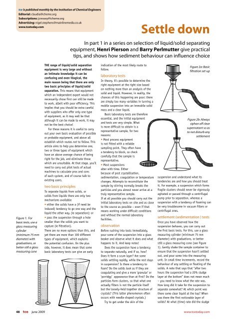
solids handling 2tce is published monthly by the Institution of Chemical EngineersEditorial: claudia@icheme.orgSubscriptions: jcressey@icheme.orgAdvertising: nigel.stephens@mainlinemedia.co.ukwww.tcetoday.comSettle downIn part 1 in a series on selection of liquid/solid separatingequipment, Henri Pierson and Barry Perlmutter give practicaltips, and shows how sediment behaviour can influence choiceFigure 1: Forbasic tests, use aglass measuringcylinder(minimum 75 mmdiameter) withgraduations, orbetter still a glassmeasuring coneTHE range of liquid/solid separationequipment is very large and withoutan intimate knowledge it can beconfusing and even illogical, themain reason being that there are onlytwo basic principles of liquid/solidseparation. This means that equipmentwhich an independent expert would notnecessarily chose first can still be madeto work, albeit with poor efficiency. Thisimplies that you should be extra carefulwith suppliers who offer only one typeof equipment, as it may well be thatalthough it can be made to work, it maynot be the best choice!For these reasons it is useful to carryout your own basic evaluation of possibleor probable equipment, and above allestablish which routes not to follow. Thisarticle aims to help you determine one,two or three types of equipment whichhave an above average chance of beingright for the job, and eliminate thosewhich are unsuitable. At that stage, you’llneed to carry out pilot tests of actualmachines to calculate pros and consof each system, and of course talk toexisting users.two basic principlesTo separate liquids from solids, orsolids from liquids there are only twomechanisms available:• either the solids have a (if need beinduced) tendency to go one way and theliquid the other way, (ie separation); or• pass the suspension through a holesmaller than the solids you want tocapture (ie filtration).There are no more options than this, andyet there are more than 100 differenttypes of equipment, which explainsthe potential confusion. On the plusside, however, it does mean that somebasic laboratory tests can give an earlyindication of the most likely route tofollow.laboratory testsIn theory, it’s possible to determine theright equipment at the right size basedon nothing more than an analysis of thesolid and liquid. However, in reality, thechances of this happening are poor; thereare simply too many variables in turning amobile suspension into an immobile solidmass and a clear liquid.Basic laboratory tests are thereforeessential, and the initial equipmentand tests are very simple. Whatis more difficult to obtain is arepresentative sample, for tworeasons:• Most process equipmentis not fitted with a reliablesampling point. They often havea tendency to block, so checkcarefully that the sample isrepresentative.• Most suspensionsalter with time. Eitherbecause of post crystallisation,sedimentation, coagulation or temperaturechanges. Attempts to reconstitute thesample by stirring normally breaks theparticles and you almost never arrive at atruly representative sample.If at all possible you should carry out theinitial laboratory tests on site and as closeto the source as possible – even if thatmeans working under difficult conditionsand without the normal laboratoryfacilities.observationBefore rushing into tests immediately,pour some of the suspension into a glassbeaker and observe what it does and whathappens to it. And keep notes!Does the suspension have a tendencyto separate naturally, and if so, how?Does it form a scum layer? Are somesolids settling rapidly, while the rest staysin suspension? Is there a tendency tofoam? Do the solids look as if they arecoagulating and give a more ‘granular’ or‘porridgy’ appearance than at first? Do theparticles form clusters, so that what oneactually filters is not the particle itselfbut the loosely-held together structure ofcrystals? (This latter phenomenon oftenoccurs with needle-shaped crystals.)Try to get under the skin of theFigure 2a: Basicfiltration set-upFigure 2b: Alwayssiphon off clearsupernatant so asto not disturb anysettlementsuspension and understand what itstendencies are and how you should treatit. For example, a suspension which formsfragile clusters should never be vigorouslyagitated or passed through a centrifugalpump prior to separation, whereas asuspension with a tendency of foaming canbe very troublesome in vacuum filters orcentrifugal ones.settlement (sedimentation ) testsOnce you have observed how thesuspension behaves, you can carry outthe first basic tests. For this, use a glassmeasuring cylinder (minimum 75 mmdiameter) with graduations, or betterstill a glass measuring cone (see Figure1). Gently shake the sample container toensure that the suspension hasn’t settledout, and pour some into the measuringunit. In small time increments, record thebehaviour of any settling or floating of thesolids. A note that says that “after twohours the suspension had a 20% sludgelayer at the bottom” does not mean much– you need to know what the rate was.How long did it take for the suspension toseparate somewhat? At which point wasthere some clear liquid at the top? Whenwas there the first noticeable layer ofsolids? At what (time) rate did the sludge48 tce june 2009 www.tcetoday.com
solids handling 2(Left to right)figures 3b and 3c:Up to 15% and40% sediment volrespectivelyHenri Pierson isdirector at <strong>BHS</strong>Filtration; BarryPerlmutter (barry.perlmutter@bhsfiltration.com)ispresident and mdof <strong>BHS</strong> Filtrationfroth flotationFroth floatation is used for particles whicheither have a tendency to float or tostay suspended. Introduction of minuteair bubbles gives the solids buoyancy,causing them to rise to the top. This canbe due to the general gentle upwards flowof the bubbles, but preferably the bubblesimpinge on the solids and take themupwards. Bubbles may be generated bydiffusers or by electrolysis.tilted plate separators (TPS)Tilted plate separators are normallyconstructed as a cube into which a largenumber of thin plates (usually plastic)are fitted at a certain angle. Feed isintroduced at the bottom, with overflowat the top. Since the spacing between theplates is quite small, particles only haveto fall a small height before reaching theplate underneath where they slide downthe slope to the sludge outlet.settlersSettlers are similar to clarifiers, but areused for suspensions with relativelyhigh solids loading. They are typicallynot as large as clarifiers and often builtabove ground as all-metal constructions,with or without scrapers depending onthe diameter, the type and percentageof solids. In sizes of up to about 5 mdiameter you could fairly safely calculatethe size, the shape and constructionwithout needing a proprietary supplier. Inthis size range a scraper is rarely requiredas long as the sidewalls of the bottomcone are not much more than 30 o from thevertical. The upflow velocity of the liquidphase should be equal to or less than thefall rate of the solids.hydrocyclonesHydrocyclones are substantially conicalin construction. Suspension enterstangentially in the straight-sided tubularsection above the cone. The entry velocitycauses the body of fluid to accelerate tocentrifugal conditions. The narrow bottomoutlet is designed so that whereas thesolids leave the machine as a wet ‘rope’,the clarified liquor reverses its directionand rises up into the ‘vortex finder’ whichis the pipe reaching inside the machineto a (variable) height. Depending onthe inlet velocity, outlet design, vortexfinder and length of the machine, varyingdegrees of clarification are possible. Theextreme simplicity of the machine beliesits efficiency. Generally considered amachine for the separation of coarse and/or dense materials, it can also be usedfor light small particles. For maximumefficiency several smaller hydrocyclonesare usually better than one big one.deep conesDeep cones are literally just that – deepcones without much of (if any) verticalwalls. Since it is used for fast-settling(and thus heavy or large) particles, acentrally-mounted auger can sometimesbe used to get the solids out of the cone.centrifugal decantersA centrifugal decanter is a roughlyconical horizontal tube which rotates atfairly high speeds causing the enteringsuspension to take on more or less thesame rotating speed and thus causing thesolid particles to be thrown out againstthe outer wall. In practically all cases,a centrally-mounted screw, rotating at adifferent speed screws the solids towardsthe outlet which is normally almosthorizontal creating a ‘beach’. You canobtain quite dry solids, but at the cost of acloudy centrate.delta decantingsettlement systemsThis is a (typically) triangular settlementsystem with a screw taking the solids overthe side. The solids have to be fairly coarseand granular for this to work reliably.inclined beltsTypically, a grooved belt of quite widedimensions and slightly curved at the sidesruns at a reasonably high speed upwardstaking fast-settling solids out of thesuspension. Inclined belts are only suitablefor large quantities with small percentagesof heavy and/or coarse solids.screensScreens, of course, aren’t sedimentationequipment, but belong to filters. However,if a suspension separates rapidly and thesolid loading is not too excessive, there isa good chance that a screen might work.Screens are always stationary but may bemechanically activated, by vibrating orshaking them to induce the solids to gointo one direction and out of the machineand/or to dislodge solids that otherwisewould gradually clog the screen. Screensmay carry extremely fine filter cloth, metalgauze, perforated sheets or bars. They aresimple, inexpensive machines and wellworth trying if they look at all hopeful. Ingeneral they scale up well from small testunits, except the sieve bends, which aresensitive to hydraulic loadings and whereadvice from the makers must be sought.construction tips for gravitysedimentation systemsSince all settlement systems may haveblockages in their (sludge) outletsit’s recommended that as a minimum,the whole sludge chamber has severalstrategically-placed (tangential) branches,fitted with suitable valves which canbe connected to either high pressurecompressed air or water to dislodge orre-pulp the sludge.In settlement systems one must expectsome ‘floaters’, ie lightweight materialthat has found its way into the system(matches, paper, plastics) as well as oil,but invariably is, eg incorporation of ascum baffle which allows for the periodicdraining of this debris.Having obtained preliminary results forsedimentation, the next stage is testing forfiltration, which we will cover in a futureissue of tce. tce50 tce june 2009 www.tcetoday.com
solids handlingfilter cakeA major part of the filtration takes placewith the filter cake acting as the filtermedium. This applies equally to batchfilters as continuous filters (see Figure2a):Phase 1 – suspension flows through theclean filter medium, some solids staybehind.Phase 2 – suspension continues to flowbut now through the partially-coatedmedium and thus at either reduced rateor higher pressure differential, moresolids stick.Phase 3 – suspension now meetsa medium with very much reducedapertures and has to flow through thecake solids. Most solids will now becaught, filtrate is cleaner, flow reducesfurther and cake starts to consolidate.Phase 4 – solids have built up on themedium until there is so much resistancethat filtration has virtually stopped.In the case of batch filters this meansstopping the filter, discharging the cake,cleaning the medium (if possible) andrestarting, whereas in continuous filtersthe cake is continuously discharged andthe medium cleaned.From this it follows that suspensionswith low percentage solids will stay fora long time in phase 1 and those withmore solids will soon reach phase 2.However, they all will have to go through2, 3 and 4. In those phases it is almostirrelevant what the original pore sizeof the filter medium was, because it isnow covered in cake solids which willalways pack to a tighter aperture thanthe original medium. In addition, thefilter cake presents a tortuous pathwhich in itself assists separation due toimpingement and even sedimentation.As such, it’s often desirable to stay aslong as possible in phases 2 and 3 as thiscan make it possible to filter to extremefiltrate clarity although the filter mediumis not particularly tight.That condition can only exist ifin phase 1 the filter medium did notbecome totally blocked (blinded) by thesolids. This can easily happen with lowsolids suspensions and especially if thefirst phase is carried out at too muchpressure, causing the solids to be ‘shot’into the filter medium at high velocity.Almost always, this also causes cakedischarge problems.In those cases you should reduce, if atall possible, the pressure and flow duringphase 1 and only increase them whenphase 2 has been reached.Equally important is the way in whichthe cake is formed, which is mainly afunction of the way in which the feedis introduced to the filter. Three basicsystems exist (see Figure 2b).• Mixed flow filtration – The feed as ahomogeneous mixture enters the filterand meets the filter element. Thereis no tendency for cake stratificationor for preferential liquid flow. Thiscondition applies to most pressure andcentrifugal filters.• Top feed filtration – The feed flowsonto a horizontal filter area (usually,by gravity) where it can be given sometime to settle out and thereby form astratified cake.• Bottom feed filtration – The liquidphase of the feed gets sucked throughthe filter medium, leaving the solids toimpinge on the medium.The mixed flow is the most commonsystem and has the theoreticaladvantage that all particles aredeposited in their natural ratio andthus the smaller ones will be able tofind apertures between the larger ones.In theory that should produce optimumfilter cakes with a minimum of residualmoisture. In practice it often leads topremature densification of the cakeand thus to reduced efficiency. Thiseffect can be offset to a large extentby keeping the initial feed pressure aslow as possible and only increasing thepressure gradually.With top feed it is possible to allowfor settlement during the first phasecausing the largest particles to settleout and thus building an open matrixfor the remainder to pass through.In practice this translates into betteroverall filtration rates, better cakedischarge and often somewhat driercakes.With bottom feed, exactly theopposite takes place. No matter howmuch you try to keep the suspensionagitated there is a tendency for thefines to be sucked onto the filtermedium in preference to the coarser(heavier) material, potentiallyproducing wetter cakes with somedischarge problems. In extreme casesit can lead to the filter acting like athickener sucking the liquid phase outof proportion, with the solids stayingin the feed trough.preliminary selection of filtersProviding the lab tests produce filtercakes of the required thickness, youcan calculate the basic theoreticalfilter area requirements simply bydividing the production capacityrequirements by the obtainedcapacity in the lab tests. Figure3 shows a preliminary selectionprocess.If the vacuum test obtains theright quality of filtrate and cake,then for both batch and continuousvacuum filters you have the choicebetween bottom-fed and top-fedmachines.If the vacuum tests are encouragingbut the rate of filtration is rather slowor the filtrate too cloudy, you canconsider pre-coat filtration (which isonly possible with bottom-fed vacuumfilters), or alternatively use flocculantsor body feed which can be used ineither type.If vacuum is not satisfactory youwill have to resort to higher filtrationforces, ie centrifugal filtration withthe option of body feed, or pressurefiltration with the options of bodyfeed, flocculants or pre-coating.If basically everything isacceptable but the cake is too wet,consider machines with inherent cakecompression or gas-blowing facility,or alternatively feed the cake into aseparate squeezing unit which is ofteneasier and cheaper. tce*For part 1, see "Settle down",p48–50, tce 816, June 2009Figure 3a: Batch filtersFigure 3b: Continuous filtersHenri Pierson isdirector at <strong>BHS</strong>Filtration; BarryPerlmutter (barry.perlmutter@bhsfiltration.com)ispresident and mdof <strong>BHS</strong> Filtrationwww.tcetoday.com july/august 2009 tce 55
solids handlingTools for the jobIn part 3* of their series on selection of liquid/solid separating equipment,Henri Pierson and Barry Perlmutter look at preliminary selection of filtersTHE selection of filters shown infigures 1a and 1b should not betaken as being exhaustive. They onlyrepresent the most popular types andit should be borne in mind that foreach type there are at least severalvariations, which can be quite distinctfrom each other. A summary of thedifferent types of filtration equipmentfollows.batch filters• auto press A horizontal pressure filterin horizontal, tubular construction; it hasa membrane in the form of a tube whichlies against the inner wall of the outertube. The outer tube with membrane canslide over a plate pack consisting of aseries of circular filter plates connectedto a filtrate drainage outlet. The platesare kept apart by compressible spacers.Prior to filtration the inflatable tubeis pressurised so that the circular filterplates have a side wall – ie the flexibletube – and thus have a cavity for cakesolids. The thickness of the final cakes isdetermined by the degree to which thespacers are being compressed, to suitthe suspension characteristics. Feed ispumped into the cavities, filtrate flowsaway, cake washing may follow. Air dryingof the cake may follow and at the endof the cycle the pressure on the spacersand the inflatable tube is relaxed, themetal outer tube is withdrawn and thecakes are discharged automatically. AutoFigure 1a: Batch filterspresses result in good cake washing anddry cakes.• bag filter A bag with a connection fora high pressure inlet held captive in ametal cage. Filtrate runs through the bagand the solids stay inside.• basket strainer Similar to the bagfilter, except that the strainer may be thefilter medium in which case the solidshave to be dug out.• basket centrifuge A metal basketrotating at centrifugal speeds. A clothbag is fitted inside the basket. Thedrive mechanism runs the basket up tohigh speeds and feed is poured into thebasket. Filtrate runs through the basketand is collected in an outer mantle. Whensufficient solids have collected insidethe bag, the machine is stopped and thesolids removed or it is slowed down toallow a mechanical scraper to remove thebulk of the solids (a ‘heel’ stays behind).In a horizontal version, the PeelerCentrifuge, the bulk of the cake can beremoved without slowing the machine.• candle filter A vertical pressure vesselwith a horizontal plate fitted to the topof the cylindrical portion. The plate hasa number of holes from which candleshang. The candles may be of a filteringmaterial (eg sintered metal) or, morecommonly, of a support structure whichenables the fitting of a ‘hose’ or ‘sock’made of filter medium.The top section of the filter (above thehorizontal plate) forms a small chamberand is fitted with an outlet branch.During operation the suspension ispumped into the main vessel with filtrateexiting into the top half from where itflows out of the outlet branch. Whensufficient solids have deposited ontothe candles, the feed is stopped; usuallycompressed air is blown through thevessel to drive off residual suspension.The removable bottom part of the filter isopened and the cake solids are blown offthe candles. In case a sludge discharge isacceptable, the bottom half stays closedbut through a reverse flow wash the cakesolids are washed off the candles and thesludge exits through a bottom outlet. Toensure fine filtration and/or to ensurereasonable cake discharge, the filtersoften work with pre-coats of some inertmaterial as well as having body-feedadded to the suspension.• cartridge filters Pressure vesselsinside which are fitted a number of filtercartridges. Almost without exceptionthe flow is from the outside inwards.Cartridges are available in cleanable or(much more common) disposable form. Avery wide variety of materials, textures,pore size and physical sizes are available.• deep bed/mixed media Mainly usedin sewage works or water treatmentinstallations, these are large circular orrectangular tanks with a drainage floorin the bottom. On top of the drainagefloor lays a bed of inert filter material ora mixed bed of inert, or inert and organicfilter medium. Flow through the bed isby gravity, the filtration being effectedmore by the tortuous path than by theapertures of the bed. For cleaning of thebed a backwashing system is used.• filter press The original filter presseswere of the ‘plate and frame’ construction.This consisted of a relatively large numberof filter plates being interspaced by filterframes. The frames and plates had lugs oneither side which allowed for the wholepack to be suspended on side bars. Theframes had the same outer dimensionas the plates but were hollow in themiddle, thus forming a cavity. The framethickness determined the cake thickness.A feed entrance port was in the wall ofthe frames. The plates had a grooved48 tce october 2009 www.tcetoday.com
solids handlingdraining surface, connected to outletports. Filter cloth was fitted to the platesand the whole pack was closed eithermechanically or hydraulically. Suspensionwould enter through the inlet ports, thefiltrate would exit through the outletports of the plates, and solids would staybehind in the cavity till flow and pressureincrease indicated that the press was fulland had to be opened, the cake removed,the cloths cleaned and the press closedagain for the next run. Modern pressesuse almost exclusively ’recessed plates’.These plates combine the drainage areaas well as the ’upstand‘ at the edge toprovide the cavity. Feed is through one ormore large ports in the plates. They aremore reliable and less prone to blockingthan the plate and frame types. They areavailable in a very wide variety of sizes,configurations, and plate supports, anddegrees of mechanisation exist.• leaf filter Leaf filters consist of apressure vessel inside which a numberof filter leaves are mounted (similar tocandle filters). The leaves are normally ofmetal and clothed with a fabric bag. Theleaves may be vertically or horizontallymounted. For removal of the solids,different arrangements exist, rangingfrom opening the bottom of the vesselto mechanically spinning or vibrating thecake into a chute.• membrane presses Not to be confusedwith membrane filters, the membranepress is basically a filter press but insteadof having drainage grooves in the plates,the plates are fitted with an elastomersheet (with has drainage grooves) whichcan be inflated. By inflating the sheetat the end of the filter cycle any residualmoisture will be expelled and the cakeitself will be squeezed, usually resultingin better cake moisture figures. Althoughmost membrane presses have theirplates vertically mounted, there existsa variation with horizontally-mountedplates. In this case the filter medium isin the form of an endless filter cloth/belt which is threaded through the platesand which, on opening of the plates, actsas a conveyor to carry the cakes out ofthe machine allowing them to drop intoa chute.• nutsche filter Circular or rectangularfilters with a drainage bottom ontowhich a filter medium is fastened. Ifthe drainage section is connected toa vacuum source the filters are oftenopen top. If they are closed at the top,they can be pressurised and thus benefitfrom a higher driving force. The filtersare fed from the top. Feed is introduceduntil an adequately thick cake is formed,thereafter the cake is drained as well aspossible (and/or washed) and the cakeis removed either manually or in case ofmechanised nutsches by means of somescraper or scroll.• sheet filters Basically identical tofilter presses except that they have avery small cavity and no filter cloth buta sheet of, usually thick, filter medium.Solids impinge on the sheet and to alarge extent lodge inside the sheet. Theyare, therefore, a combination of surfaceand depth filtration, and are obviouslyonly suitable for extremely low solidcontents.• tube press These may be vertical orhorizontal, and consist of a metal tubewhich has an inflatable membrane fitted.Inside this membrane is mounted acentral filter core consisting of a drainagetube, suitably clothed with filter medium.The feed is introduced into the tubeunder pressure, filtrate exits from thecentral filter core. After filtration and/or washing the membrane is inflated tosqueeze the cake solids to extremely lowresidual moisture values. To dischargethe cake, the membrane is relaxed, thebottom section of the tube opened andthe tube slightly or totally withdrawn,allowing the cake solids to drop off or tobe scraped off.continuous filters• brushed screen Often circular screenswith the flow entering at the inside.Rotating brushes remove all or mostof the debris, which falls to a bottomreceptacle from which it can be removedperiodically.• compression belts Two endless sievebeltswhich are configured so that thetwo belts form a ‘throat’ at one end intowhich the suspension enters. After thethroat the belts run gradually closer toone another until almost touching. Thisproduces the squeezing action requiredto dewater the suspension. In order toobtain more squeezing effect, oftenextra pulleys are introduced so thatthe two belts form a zigzag pattern.Horizontal configurations are mostcommon, although vertical ones exist.For them to work the suspension hasto be quite thick and often requirescoagulants.• curved screen A substantially verticalscreen, normally made of wedge wire.The screen has a curvature, and afeed box with overflow weir is fittedto the top. The suspension overflowsonto the screen’s curved surfaceand it is the hydraulic action of theoncoming suspension that pushesthe collected solids down the screeninto a solid-collecting receptacle. Ifproperly calculated and installed, quiteremarkable efficiencies can be obtained,although they are sensitive to hydraulicload changes.• disc filter In essence a flat discmounted on a hollow shaft. The discis made of metal and has on eitherside an open cloth support structurewhich connects with the hollow shaftwhich carries the filtrate. A filter clothis fastened to the disc and the hollowshaft connects to a vacuum source. Thedisc, usually 30% submerged, rotatesslowly in a feed trough where it picks upthe solids, which can later be scrapedoff just prior to re-entry into the feedtrough. To facilitate manufacturingand maintenance, most disc filters donot have complete discs, but the ’disc‘consists of roughly triangular elementswhich screw onto the hollow shaft. Ingeneral, disc filters are most suitable forfibrous suspensions.Figure 1b: Continuous filterswww.tcetoday.com october 2009 tce 49
solids handling• edge filter The continuous edge filterconsists of a filter cage which is mountedinside a pressure chamber. The cage isnormally made of vertically-mountedwedge wire. The cage itself is mountedon a structure which resembles a femalegear-ring except that the ’teeth‘ arenot connected but are separate fromeach other. A small pinion-like wheelengages with the teeth in the outer ring.Depending on the design, the pinionis static and the filter cage rotates orvice versa. Filtration is from the outsideinwards. When the pinion engages witha tooth, it acts like a gear pump andpresses some of the collected filtrateoutwards, dislodging the solids on theedge of the screen.• fest filter Also known as a ’rotarypressure filter‘, it has a rotating coreonto which are mounted ’pockets’ fittedwith drainage plates and filter medium.The pockets are connected to a rotatingoutlet valve which connects with afiltrate collection system. The core withpockets is mounted inside a pressurechamber. The inside of the pressurechamber has division strips which runlongitudinally and are almost touchingthe pocket walls. In this way each orseveral rows of pockets can be separatedfrom one another. Assuming clockwiseoperation, the feed is introduced at about5 o’clock position. This may be followedwith cake washing at, for example,8 o’clock, cake drying with compressed(hot or cold) gas at 12 o’clock and finallyat the 3 o’clock position the pocketsmeet a discharge scoop which scoops thecake from the pocket and into a dischargechute. Medium washing may follow.Depending on the size and design, quitehigh filtration pressures can be used.• pusher centrifuge A horizontallymountedfiltering centrifuge with a filtercage made of metal bars, the smallestopening of which is about 100 µm.Inside the cage is a ’pusher’ arrangement,basically a sturdy ring which lies veryclose to the filter medium. The ringis connected to a central shaft whichrotates at the same speed as the filtercage but reciprocates (approximately1–3 cm) causing the collected solids tobe pushed out of the machine. Multistagemachines exist. In these, the solidsare pushed onto the second or thirdstage, which each time is of a largerdiameter. The higher linear velocityas well as the tumbling action can bebeneficial for dewatering and/or cakewashing, although it may cause thecrystals to fracture.• rotary drum filter The original rotarydrum filter consisted of a cylindricaldrum, fitted with a drainage grid on theoutside over which a filter cloth wasstretched. The drum had perforations andwas connected to a vacuum source. Thedrum itself was mounted on a horizontalshaft and submerged for about 30% ina feed trough. The vacuum caused theliquor phase to be sucked through thecloth, leaving the solids behind as afilter cake. The cake was scraped off justbefore re-entering the feed trough.This design, or variations on it, isparticularly useful for pre-coat filtration,where the drum filter can be used tofilter ultra-fine suspensions. In thiscase there is no cake as such but a finelayer of slimy solids. These are removedwith a very small amount of pre-coatmaterial by a knife which advances apre-determined distance.Although the principle remains thesame, the modern rotary drum filter hasdiscrete filter segments mounted on thedrum surface, with individual tubingleading to a rotating head valve, sothat sections can be drained to separateoutlets (filtrate and wash) and above allso that in the cake discharge positionvacuum can be disconnected causing thecake to be much easier to remove.A further development of this is therotary vacuum belt filter, which borrowsits name from the filter cloth beingin the form of an endless belt whichcan leave the drum to facilitate cakedischarge and allow for cloth washingbefore joining the drum on re-entry intothe feed trough.• screw press An almost always conicalfilter cage with an auger inside whichtransports and squeezes the solidsthrough the cage. They are only suitablefor fibrous suspensions where squeezingwith a very high line pressure isbeneficial.• tipping pan filter In its basic form,a filter tray consisting of a filtratecollection box connected to a vacuumsource. A drainage grid is mountedinside the box, suitably clothed with afilter cloth. The whole arrangement canbe tipped over 180º, causing the cake todrop out. This obviously is a batch filterbut the same principle is used in therotary tipping pan filter, where a verylarge horizontal wheel of several metresdiameter is formed through triangularfilter trays connected to a central driveand tipping mechanism. The wheelrotates the filter segments through thefeed, dewatering, cake wash and finaldrying stages after which each individualtray is turned 180º, sometimes followedby cloth washing. The filtrationmechanism and efficiency is very similarto that of a vacuum belt filter. Althoughvery large filter areas can be offered,the circular shape is responsible for verylarge floor space occupation.• vacuum belt filter Structurally,these filters resemble a conveyor belt,except that the essential belt is a filtermedium which is subjected to a vacuumsource. Feed is introduced at one end,where it is normally allowed to settleunder gravity for a few seconds, causingthe coarser fraction to form its ownpre-coat. Thereafter the suspension issubjected to full vacuum application.Since the cake thickness can becontrolled almost at will by increasingor reducing the speed of travel, onecan filter at optimum cake thickness toobtain the required residual moistureand/or the required cake washingefficiency. The horizontal configurationmakes this filter one of the mostefficient cake washing filters, especiallyfor counter current washings.Two mechanically different typesexist. One supports the filter cloth ona rubber carrier (and drainage) belt,which in turn runs on a sealing beltwhich forms the seal between therubber carrier belt and the vacuum box.The other types are inherently simpleras they do not rely on any carrier beltsbut support the filter cloths on thevacuum boxes. Open and gas-tightconstructions are available.pilot testsSince it is more than likely that atsome stage pilot tests will have tobe carried out, we would emphasisethe importance to over-budget bothin terms of money, time, space andmanpower. Due to the provisionalnature of the installation thingsrarely (if ever) go according to plan.Temporary pipelines, flexible hoses,inadequate auxiliary services, poorworking conditions, not to mention thedifficulties of getting representativefeed to the equipment, all spantogether to make life unpredictable.Pilot tests are valuable, ofteneven essential, but allow plenty ofeverything for them. If not, the resultswill be meaningless and expensivemisinformation. tcefurther readingSvarovsky, Solid-Liquid Separation, ISBN0-408-03765-2, Butterworths*For part 1, see "Settle down",p48–50, tce 816, June 2009. Forpart 2, see "The solution is clear"p53–55, tce 817/8, August 2009Henri Pierson isdirector at <strong>BHS</strong>Filtration; BarryPerlmutter (barry.perlmutter@bhsfiltration.com)ispresident and mdof <strong>BHS</strong> Filtration50 tce october 2009 www.tcetoday.com