2001-2003 Transmission Removal and Installation Manual
2001-2003 Transmission Removal and Installation Manual
2001-2003 Transmission Removal and Installation Manual

Create successful ePaper yourself
Turn your PDF publications into a flip-book with our unique Google optimized e-Paper software.
<strong>2003</strong> Volkswagen EuroVan MVREMOVAL & INSTALLATION - A/T (01P)4 января 2005 г. 1:03:46 Page 3 © 2004 Mitchell Repair Information Company, LLC.
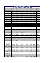
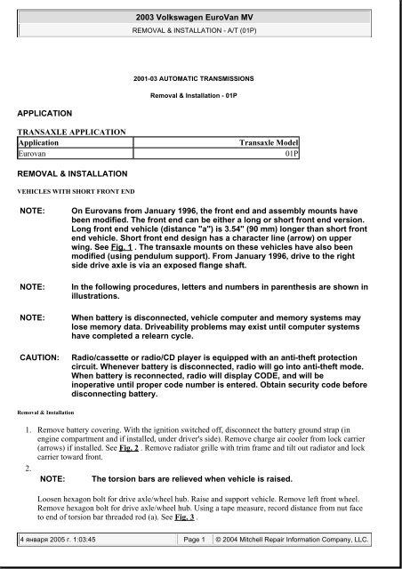
<strong>2003</strong> Volkswagen EuroVan MVREMOVAL & INSTALLATION - A/T (01P)Fig. 3: Measuring Distance From Nut To End Of Torsion Bar RodCourtesy of VOLKSWAGEN UNITED STATES, INC.4 января 2005 г. 1:03:46 Page 5 © 2004 Mitchell Repair Information Company, LLC.
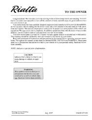
<strong>2003</strong> Volkswagen EuroVan MVREMOVAL & INSTALLATION - A/T (01P)Fig. 4: Relieving Torsion Bar TensionCourtesy of VOLKSWAGEN UNITED STATES, INC.4 января 2005 г. 1:03:46 Page 6 © 2004 Mitchell Repair Information Company, LLC.
<strong>2003</strong> Volkswagen EuroVan MVREMOVAL & INSTALLATION - A/T (01P)Fig. 5: Pulling Out Radiator Toward Front Of VehicleCourtesy of VOLKSWAGEN UNITED STATES, INC.4.NOTE:Mark position of engine/transaxle connecting bolts before removal <strong>and</strong>only use bolts of same length when replacing.Remove noise insulation tray. Pull electrical connections off transaxle at valve body (1), vehicle speedsensor (2) <strong>and</strong> multifunction TR switch (3). See Fig. 6 . Remove multifunction TR switch cable <strong>and</strong>holder from transaxle <strong>and</strong> position to one side. Remove starter. Unbolt drive axles from transaxleflange shafts. Raise right drive axle <strong>and</strong> secure out of the way.5. Unbolt flanged shaft bearing (A) from transaxle mount (B) at arrow. Pull right h<strong>and</strong> flange shaft (C)out from intermediate shaft (D). See Fig. 7 . Detach front exhaust pipe at exhaust manifold. Removebolts (arrows) for cover plate. See Fig. 8 .6. Remove nut (arrow) from torque converter. Rotate torque converter to remove additional nuts (2). SeeFig. 9 . Separate left h<strong>and</strong> wheel bearing housing/lower swivel joint bolted connection. See Fig. 10 .Always replace bolts. Remove bolt for left h<strong>and</strong> shock absorber/stabilizer bar coupling rod. Push left4 января 2005 г. 1:03:46 Page 7 © 2004 Mitchell Repair Information Company, LLC.
<strong>2003</strong> Volkswagen EuroVan MVREMOVAL & INSTALLATION - A/T (01P)h<strong>and</strong> shock absorber together. Remove auxiliary heater end pipe, if installed.Fig. 6: Disconnecting Wiring Connections On TransaxleCourtesy of VOLKSWAGEN UNITED STATES, INC.4 января 2005 г. 1:03:46 Page 8 © 2004 Mitchell Repair Information Company, LLC.
<strong>2003</strong> Volkswagen EuroVan MVREMOVAL & INSTALLATION - A/T (01P)Fig. 7: Removing Flanged Shaft Bearing From TransaxleCourtesy of VOLKSWAGEN UNITED STATES, INC.4 января 2005 г. 1:03:46 Page 9 © 2004 Mitchell Repair Information Company, LLC.
<strong>2003</strong> Volkswagen EuroVan MVREMOVAL & INSTALLATION - A/T (01P)Fig. 8: Removing Cover Plate BoltsCourtesy of VOLKSWAGEN UNITED STATES, INC.4 января 2005 г. 1:03:46 Page 10 © 2004 Mitchell Repair Information Company, LLC.
<strong>2003</strong> Volkswagen EuroVan MVREMOVAL & INSTALLATION - A/T (01P)Fig. 9: Removing Torque Converter NutCourtesy of VOLKSWAGEN UNITED STATES, INC.4 января 2005 г. 1:03:46 Page 11 © 2004 Mitchell Repair Information Company, LLC.
<strong>2003</strong> Volkswagen EuroVan MVREMOVAL & INSTALLATION - A/T (01P)Fig. 10: Removing Wheel Bearing Housing/Lower Swivel Joint BoltCourtesy of VOLKSWAGEN UNITED STATES, INC.7.NOTE:Engine Support (3227) may also be used to support engine on somevehicles.Install Support Device (3184) to support engine/transaxle assembly. Install Engine Support (3227) toengine block, as necessary. See Fig. 11 . Hook Auxiliary Support (3184/1) for Support Device (3184)in cross panel (arrow). See Fig. 12 . If necessary, remove wiring harnesses <strong>and</strong> pipes from cross panel.8. Install Support Device (3184) into Auxiliary Support (3184/1) <strong>and</strong> into subframe (A). Screw spindle(C) into hole on engine mount. Align support device so that the slide (B) is resting against the righth<strong>and</strong> tube (arrow). Secure support device to subframe (A) <strong>and</strong> to Auxiliary Support (3184/1) bytightening the angle plates. Relieve subframe load by raising engine/transaxle using spindle (C). SeeFig. 13 .9. Remove pendulum support by removing bolts (A <strong>and</strong> B). See Fig. 14 . Unbolt transaxle mount from4 января 2005 г. 1:03:47 Page 12 © 2004 Mitchell Repair Information Company, LLC.
<strong>2003</strong> Volkswagen EuroVan MVREMOVAL & INSTALLATION - A/T (01P)body (arrow 1). Carefully lower engine using support device spindle. Unbolt bearing block fromtransaxle (arrow 2). See Fig. 15 .Fig. 11: Installing Engine SupportCourtesy of VOLKSWAGEN UNITED STATES, INC.4 января 2005 г. 1:03:47 Page 13 © 2004 Mitchell Repair Information Company, LLC.
<strong>2003</strong> Volkswagen EuroVan MVREMOVAL & INSTALLATION - A/T (01P)Fig. 12: Attaching Auxiliary SupportCourtesy of VOLKSWAGEN UNITED STATES, INC.4 января 2005 г. 1:03:47 Page 14 © 2004 Mitchell Repair Information Company, LLC.
<strong>2003</strong> Volkswagen EuroVan MVREMOVAL & INSTALLATION - A/T (01P)Fig. 13: Raising Engine/Transaxle Assembly Using Support Device & Auxiliary SupportCourtesy of VOLKSWAGEN UNITED STATES, INC.4 января 2005 г. 1:03:47 Page 15 © 2004 Mitchell Repair Information Company, LLC.
<strong>2003</strong> Volkswagen EuroVan MVREMOVAL & INSTALLATION - A/T (01P)Fig. 14: Removing Pendulum SupportCourtesy of VOLKSWAGEN UNITED STATES, INC.4 января 2005 г. 1:03:47 Page 16 © 2004 Mitchell Repair Information Company, LLC.
<strong>2003</strong> Volkswagen EuroVan MVREMOVAL & INSTALLATION - A/T (01P)Fig. 15: Unbolting Transaxle Mount & Bearing BlockCourtesy of VOLKSWAGEN UNITED STATES, INC.10. Carefully swivel engine/transaxle forward <strong>and</strong> lower, thereby ensuring that the selector lever cable,multifunction TR switch <strong>and</strong> drive axles are not damaged. To swivel forward, turn spindle (D) to theleft. To swivel back, turn spindle (D) to the right. See Fig. 13 . Ensure that the selector lever cabledoes not become tightened. Unclip selector lever cable securing clips <strong>and</strong> detach selector lever cable.Clamp off ATF cooler hoses <strong>and</strong> detach at ATF cooler.11. Tilt engine/transaxle further forward <strong>and</strong> lower. Ensure sufficient clearance exists between engine <strong>and</strong>vehicle longitudinal member. Loosen alternator <strong>and</strong> remove tensioning arm from engine, if necessary.Remove left h<strong>and</strong> drive axle, ensuring multifunction TR switch is not damaged.12.NOTE: The support element (C) can be used with the corresponding hole(arrow) in the adjustment plate to remove the transaxle in cases where4 января 2005 г. 1:03:47 Page 17 © 2004 Mitchell Repair Information Company, LLC.
<strong>2003</strong> Volkswagen EuroVan MVREMOVAL & INSTALLATION - A/T (01P)the engine has a metal oil sump. Once the torque converter cover hasbeen removed, the support element (C) should be bolted tight to thetorque converter housing. See Fig. 16 .Set up Transaxle Support (3282). The Transaxle Support (3282) is set up with the Adjustment Plate(3282/22A) for removal of transaxle. Bolt on Support Elements (A), as shown in illustration ofadjustment plate. See Fig. 16 <strong>and</strong> Fig. 17 . Move Transaxle Jack (VAG 1383A) with Transaxle Mount(3282) under the transaxle <strong>and</strong> support transaxle. The arrow (B) on the adjustment plate points indirection of normal travel. Secure Transaxle Support (3282) with drilled plate to the pendulumsupport bushing (arrow). See Fig. 18 .13. Remove lower engine/transaxle connecting bolts. Press transaxle off engine, while pressing torqueconverter out of drive plate. Press torque converter against ATF pump. Lower transaxle slightly.Swivel transaxle <strong>and</strong> carefully lower. Secure torque converter to prevent it from falling out.14. To install transaxle, reverse removal procedure. When installing the torque converter, ensure that bothdrive pins engage in the ATF pump inner wheel recesses. Always replace self locking nuts <strong>and</strong> bolts.Before installing, ensure that the dowel sleeves are correctly located.15. Before installing starter mounting bushing, check for wear <strong>and</strong> replace, if necessary. Before installingpendulum support bushing, check for wear <strong>and</strong> replace, if necessary. While swinging transaxleinward, install both drive axles in the flanged shaft <strong>and</strong> drive flange.Fig. 16: Identifying Adjustment Plate Direction4 января 2005 г. 1:03:47 Page 18 © 2004 Mitchell Repair Information Company, LLC.
<strong>2003</strong> Volkswagen EuroVan MVREMOVAL & INSTALLATION - A/T (01P)Courtesy of VOLKSWAGEN UNITED STATES, INC.Fig. 17: Installing Adjustment Plate To Transaxle SupportCourtesy of VOLKSWAGEN UNITED STATES, INC.4 января 2005 г. 1:03:47 Page 19 © 2004 Mitchell Repair Information Company, LLC.
<strong>2003</strong> Volkswagen EuroVan MVREMOVAL & INSTALLATION - A/T (01P)Fig. 18: Securing Transaxle Support To Pendulum SupportCourtesy of VOLKSWAGEN UNITED STATES, INC.16.WARNING:Do not remove Support Device (3184) until the bolts securing the lefth<strong>and</strong> bearing bracket have been securely tightened.Before lifting engine/transaxle, tighten bolts (arrows 2) to specification. After lifting engine/transaxle,tighten nuts (arrow 1) to specification. See Fig. 15 . Tighten all nuts <strong>and</strong> bolts to specification. SeeTORQUE SPECIFICATIONS .17. Adjust torsion bar threaded rod distance. See Fig. 3 . Check selector lever cable adjustment, <strong>and</strong>adjust as necessary. Check <strong>and</strong> top off ATF level. See SERVICING - EUROVAN article.VEHICLES WITH LONG FRONT END<strong>Removal</strong> & <strong>Installation</strong>NOTE:In the following procedures, letters <strong>and</strong> numbers in parenthesis are shown inillustrations.4 января 2005 г. 1:03:47 Page 20 © 2004 Mitchell Repair Information Company, LLC.
<strong>2003</strong> Volkswagen EuroVan MVREMOVAL & INSTALLATION - A/T (01P)NOTE:When battery is disconnected, vehicle computer <strong>and</strong> memory systems maylose memory data. Driveability problems may exist until computer systemshave completed a relearn cycle.CAUTION:Radio/cassette or radio/CD player is equipped with an anti-theft protectioncircuit. Whenever battery is disconnected, radio will go into anti-theft mode.When battery is reconnected, radio will display CODE, <strong>and</strong> will beinoperative until proper code number is entered. Obtain security code beforedisconnecting battery.1. Remove battery covering. With the ignition switched off, disconnect the battery ground strap (inengine compartment <strong>and</strong> if installed, under driver's side). Loosen hex bolt for drive axle/wheel hub.Raise <strong>and</strong> support vehicle. Remove left front wheel. Remove hex bolt for drive axle/wheel hub.2.NOTE: Mark position of engine/transaxle connecting bolts before removal <strong>and</strong>only use bolts of same length when replacing.NOTE:The torsion bars are relieved when vehicle is raised.Remove upper engine/transaxle connecting bolts. Pull upper connector off transaxle (transaxle vehiclespeed sensor). Using a tape measure, record distance from nut face to end of torsion bar threaded rod(a). See Fig. 3 . Relieve tension on torsion bar with Special Socket (3257). See Fig. 4 . Remove noiseinsulation tray.3. Remove electrical connections (arrows) at transaxle. See Fig. 19 . Pull connector off speedometersender. Remove starter. Unbolt drive axles from transaxle flange shafts. Raise right drive axle <strong>and</strong>secure out of the way. Remove transaxle carrier (A) bolts (arrows) for right h<strong>and</strong> flanged shaftbearing. Pull out flanged shaft (B). See Fig. 20 .4. Detach front exhaust pipe at exhaust manifold. Remove bolts (arrows) for cover plate. See Fig. 8 .Remove nut (arrow) from torque converter. Rotate torque converter to remove additional nuts (2). SeeFig. 9 .5. Remove pendulum support by removing bolts (A <strong>and</strong> B). See Fig. 14 . Using appropriate socket (1),separate left h<strong>and</strong> wheel bearing housing/lower swivel joint bolted connection. See Fig. 21 . Alwaysreplace bolts.6. Remove bolt for left h<strong>and</strong> shock absorber/stabilizer bar coupling rod. Press drive axle out of wheelbearing housing. Push left h<strong>and</strong> shock absorber together. Remove left h<strong>and</strong> drive axle, ensuringmultifunction TR switch is not damaged. Remove auxiliary heater end pipe, if installed.4 января 2005 г. 1:03:47 Page 21 © 2004 Mitchell Repair Information Company, LLC.
<strong>2003</strong> Volkswagen EuroVan MVREMOVAL & INSTALLATION - A/T (01P)Fig. 19: Disconnecting Wiring Connections At TransaxleCourtesy of VOLKSWAGEN UNITED STATES, INC.4 января 2005 г. 1:03:47 Page 22 © 2004 Mitchell Repair Information Company, LLC.
<strong>2003</strong> Volkswagen EuroVan MVREMOVAL & INSTALLATION - A/T (01P)Fig. 20: Removing Transaxle Carrier For Right H<strong>and</strong> Flanged Shaft BearingCourtesy of VOLKSWAGEN UNITED STATES, INC.4 января 2005 г. 1:03:47 Page 23 © 2004 Mitchell Repair Information Company, LLC.
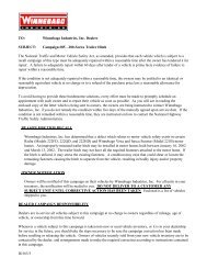
<strong>2003</strong> Volkswagen EuroVan MVREMOVAL & INSTALLATION - A/T (01P)Fig. 21: Separating Left H<strong>and</strong> Wheel Bearing Housing From Lower Swivel JointCourtesy of VOLKSWAGEN UNITED STATES, INC.7. Remove engine/transaxle securing bolt (arrow). See Fig. 22 . Install Retainer (3407) to engine. SeeFig. 23 . Install Support Device (10-222A) in conjunction with Supports (10-222 A/6). Attach Hook(10-222 A/2) <strong>and</strong> Auxiliary Hook (10-222 A/7) in left h<strong>and</strong> support spindle. See Fig. 24 . AttachAuxiliary Hook (10-222 A/7) in Retainer (3407). See Fig. 23 . Attach Hook (10-222 A/2) in righth<strong>and</strong> support spindle <strong>and</strong> on engine. Tighten engine/transaxle assembly on the spindles.8. Unclip selector lever cable securing clips <strong>and</strong> detach selector lever cable. Clamp off ATF cooler hoses<strong>and</strong> detach at ATF cooler.9.NOTE: The support element (C) can be used with the corresponding hole(arrow) in the adjustment plate to remove the transaxle in cases wherethe engine has a metal oil sump. Once the torque converter cover has4 января 2005 г. 1:03:48 Page 24 © 2004 Mitchell Repair Information Company, LLC.
<strong>2003</strong> Volkswagen EuroVan MVREMOVAL & INSTALLATION - A/T (01P)been removed, the support element (C) should be bolted tight to thetorque converter housing. See Fig. 16 .Set up Transaxle Support (3282). The Transaxle Support (3282) is set up with the Adjustment Plate(3282/22A) for removal of transaxle. Bolt on Support Elements (A), as shown in illustration ofadjustment plate. See Fig. 16 <strong>and</strong> Fig. 17 .10. Move Transaxle Jack (VAG 1383A) with Transaxle Mount (3282) under the transaxle <strong>and</strong> supporttransaxle. The arrow (B) on the adjustment plate points in direction of normal travel. Secure TransaxleSupport (3282) with drilled plate to the pendulum support bushing (arrow). See Fig. 18 .11.NOTE: To remove securing nuts, use step ladder as necessary.Unbolt transaxle mount from body (arrow 1). See Fig. 15 . Carefully lower engine/transaxle assemblyvia spindles of support device <strong>and</strong>, at the same time, via the Transaxle Jack (VAG 1383A). Unboltbearing block with transaxle mount from transaxle (arrow 2). See Fig. 15 .12. Remove lower engine/transaxle connecting bolts. Press transaxle off engine, while pressing torqueconverter out of drive plate. Press torque converter against ATF pump. Swivel transaxle <strong>and</strong> carefullylower. Secure torque converter to prevent it from falling out.13. To install transaxle, reverse removal procedure. When installing the torque converter, ensure that bothdrive pins engage in the ATF pump inner wheel recesses. Always replace self locking nuts <strong>and</strong> bolts.Before installing, ensure that the dowel sleeves are correctly located.14. Before installing starter mount bushing, check for wear <strong>and</strong> replace, if necessary. Before installingpendulum support bushing, check for wear <strong>and</strong> replace, if necessary. Install left h<strong>and</strong> drive axle.15.WARNING: Do not remove Support Device (10-222A) until the bolts securing theleft <strong>and</strong> right assembly mounts have been securely tightened.Before lifting engine/transaxle, tighten bolts (arrows 2) to specification. After lifting engine/transaxle,tighten nuts (arrow 1) to specification. See Fig. 15 . First tighten transaxle carrier (A) bolts on engineto specification, then tighten flanged shaft (B) bearing bolts to specification. See Fig. 20 . Tighten allnuts <strong>and</strong> bolts to specification. See TORQUE SPECIFICATIONS .16. Adjust torsion bar threaded rod distance. See Fig. 3 . Check selector lever cable adjustment, <strong>and</strong>adjust as necessary. Check <strong>and</strong> top off ATF level. See SERVICING - EUROVAN article.4 января 2005 г. 1:03:48 Page 25 © 2004 Mitchell Repair Information Company, LLC.
<strong>2003</strong> Volkswagen EuroVan MVREMOVAL & INSTALLATION - A/T (01P)Fig. 24: Installing Support Device With Adapters & HooksCourtesy of VOLKSWAGEN UNITED STATES, INC.TORQUE SPECIFICATIONSTORQUE SPECIFICATIONSApplicationFt. Lbs. (N.m)Cover Plate-To-Transaxle Bolt 11 (15)Drive Axle-To-Wheel Hub Bolt (1) 111 (150)Left H<strong>and</strong> Transaxle MountBolt (2) 37 (50)Nut 41 (55)Lower Control Arm-To-Wheel Bearing Housing Bolt (3) 66 (90)Torque Converter-To-Drive Plate Nut 44 (60)Transaxle Carrier Flanged Shaft Bearing-To-Engine Bolt (4) 30 (40)Transaxle Carrier Flanged Shaft Bearing-To-Flange Bolt (4) 18 (25)4 января 2005 г. 1:03:48 Page 28 © 2004 Mitchell Repair Information Company, LLC.
<strong>2003</strong> Volkswagen EuroVan MVREMOVAL & INSTALLATION - A/T (01P)Transaxle Mounting-To-Bearing Housing Bolt 18 (25)Transaxle Mounting-To-Engine Bolt 30 (40)Transaxle-To-Engine BoltM 8 Bolt 17 (23)M 10 Bolt 44 (60)M 12 Bolt 59 (80)(1) Tighten bolt to specification plus an additional 90 degrees.(2) Tighten bolt to specification plus an additional 90 degrees. See Fig. 15 .(3) Tighten bolt to specification plus an additional 90 degrees. See Fig. 10 .(4) For bolt locations, see Fig. 20 .4 января 2005 г. 1:03:48 Page 29 © 2004 Mitchell Repair Information Company, LLC.