2001-2003 Transmission Removal and Installation Manual
2001-2003 Transmission Removal and Installation Manual
2001-2003 Transmission Removal and Installation Manual
Create successful ePaper yourself
Turn your PDF publications into a flip-book with our unique Google optimized e-Paper software.
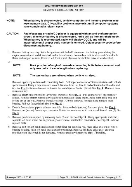
<strong>2003</strong> Volkswagen EuroVan MVREMOVAL & INSTALLATION - A/T (01P)NOTE:When battery is disconnected, vehicle computer <strong>and</strong> memory systems maylose memory data. Driveability problems may exist until computer systemshave completed a relearn cycle.CAUTION:Radio/cassette or radio/CD player is equipped with an anti-theft protectioncircuit. Whenever battery is disconnected, radio will go into anti-theft mode.When battery is reconnected, radio will display CODE, <strong>and</strong> will beinoperative until proper code number is entered. Obtain security code beforedisconnecting battery.1. Remove battery covering. With the ignition switched off, disconnect the battery ground strap (inengine compartment <strong>and</strong> if installed, under driver's side). Loosen hex bolt for drive axle/wheel hub.Raise <strong>and</strong> support vehicle. Remove left front wheel. Remove hex bolt for drive axle/wheel hub.2.NOTE: Mark position of engine/transaxle connecting bolts before removal <strong>and</strong>only use bolts of same length when replacing.NOTE:The torsion bars are relieved when vehicle is raised.Remove upper engine/transaxle connecting bolts. Pull upper connector off transaxle (transaxle vehiclespeed sensor). Using a tape measure, record distance from nut face to end of torsion bar threaded rod(a). See Fig. 3 . Relieve tension on torsion bar with Special Socket (3257). See Fig. 4 . Remove noiseinsulation tray.3. Remove electrical connections (arrows) at transaxle. See Fig. 19 . Pull connector off speedometersender. Remove starter. Unbolt drive axles from transaxle flange shafts. Raise right drive axle <strong>and</strong>secure out of the way. Remove transaxle carrier (A) bolts (arrows) for right h<strong>and</strong> flanged shaftbearing. Pull out flanged shaft (B). See Fig. 20 .4. Detach front exhaust pipe at exhaust manifold. Remove bolts (arrows) for cover plate. See Fig. 8 .Remove nut (arrow) from torque converter. Rotate torque converter to remove additional nuts (2). SeeFig. 9 .5. Remove pendulum support by removing bolts (A <strong>and</strong> B). See Fig. 14 . Using appropriate socket (1),separate left h<strong>and</strong> wheel bearing housing/lower swivel joint bolted connection. See Fig. 21 . Alwaysreplace bolts.6. Remove bolt for left h<strong>and</strong> shock absorber/stabilizer bar coupling rod. Press drive axle out of wheelbearing housing. Push left h<strong>and</strong> shock absorber together. Remove left h<strong>and</strong> drive axle, ensuringmultifunction TR switch is not damaged. Remove auxiliary heater end pipe, if installed.4 января 2005 г. 1:03:47 Page 21 © 2004 Mitchell Repair Information Company, LLC.


