IP Telephony Cookbook
IP Telephony Cookbook
IP Telephony Cookbook

You also want an ePaper? Increase the reach of your titles
YUMPU automatically turns print PDFs into web optimized ePapers that Google loves.
<strong>IP</strong> <strong>Telephony</strong> <strong>Cookbook</strong>Dr. Margit Brandl,Dimitris Daskopoulos,Erik Dobbelsteijn,Dr. Rosario Giuseppe Garroppo,Jan Janak,Jiri Kuthan,Saverio Niccolini,Dr. Jörg Ott,Stefan Prelle,Dr. Sven Ubik,Egon VerharenMarch 9, 2004
Contents1 Introduction 111.1 Goal . . . . . . . . . . . . . . . . . . . . . . . . . . . . . . . . . . . . . . . . . . . . . . . . . . 111.2 Reasons for writing this document . . . . . . . . . . . . . . . . . . . . . . . . . . . . . . . . 111.3 Contents . . . . . . . . . . . . . . . . . . . . . . . . . . . . . . . . . . . . . . . . . . . . . . . 111.4 How to read this document . . . . . . . . . . . . . . . . . . . . . . . . . . . . . . . . . . . . 121.5 Techno-economic aspect of moving from classic telephony to Vo<strong>IP</strong> . . . . . . . . . . . . . . 122 Technology Background 152.1 Components . . . . . . . . . . . . . . . . . . . . . . . . . . . . . . . . . . . . . . . . . . . . . 152.1.1 Terminal . . . . . . . . . . . . . . . . . . . . . . . . . . . . . . . . . . . . . . . . . . . 152.1.2 Server . . . . . . . . . . . . . . . . . . . . . . . . . . . . . . . . . . . . . . . . . . . . 152.1.3 Gateway . . . . . . . . . . . . . . . . . . . . . . . . . . . . . . . . . . . . . . . . . . . 152.1.4 Conference Bridge . . . . . . . . . . . . . . . . . . . . . . . . . . . . . . . . . . . . . 162.1.5 Addressing . . . . . . . . . . . . . . . . . . . . . . . . . . . . . . . . . . . . . . . . . 162.2 Protocols . . . . . . . . . . . . . . . . . . . . . . . . . . . . . . . . . . . . . . . . . . . . . . . 162.2.1 H.323 . . . . . . . . . . . . . . . . . . . . . . . . . . . . . . . . . . . . . . . . . . . . . 162.2.1.1 Scope . . . . . . . . . . . . . . . . . . . . . . . . . . . . . . . . . . . . . . . 172.2.1.2 Signaling protocols . . . . . . . . . . . . . . . . . . . . . . . . . . . . . . . 182.2.1.3 Gatekeeper Discovery and Registration . . . . . . . . . . . . . . . . . . . . 202.2.1.4 Signaling models . . . . . . . . . . . . . . . . . . . . . . . . . . . . . . . . 212.2.1.5 Communication Phases . . . . . . . . . . . . . . . . . . . . . . . . . . . . . 242.2.1.6 Locating zone external targets . . . . . . . . . . . . . . . . . . . . . . . . . 282.2.1.7 Sample Call Scenario . . . . . . . . . . . . . . . . . . . . . . . . . . . . . . 292.2.1.8 Additional (Call) Services . . . . . . . . . . . . . . . . . . . . . . . . . . . . 292.2.1.9 H.235 Security . . . . . . . . . . . . . . . . . . . . . . . . . . . . . . . . . . 302.2.1.10 Protocol Profiles . . . . . . . . . . . . . . . . . . . . . . . . . . . . . . . . . 312.2.2 S<strong>IP</strong> . . . . . . . . . . . . . . . . . . . . . . . . . . . . . . . . . . . . . . . . . . . . . . 312.2.2.1 Purpose of S<strong>IP</strong> . . . . . . . . . . . . . . . . . . . . . . . . . . . . . . . . . . 312.2.2.2 S<strong>IP</strong> Network Elements . . . . . . . . . . . . . . . . . . . . . . . . . . . . . 322.2.2.3 S<strong>IP</strong> Messages . . . . . . . . . . . . . . . . . . . . . . . . . . . . . . . . . . . 342.2.2.4 S<strong>IP</strong> Transactions . . . . . . . . . . . . . . . . . . . . . . . . . . . . . . . . . 382.2.2.5 S<strong>IP</strong> Dialogs . . . . . . . . . . . . . . . . . . . . . . . . . . . . . . . . . . . . 382.2.2.6 Typical S<strong>IP</strong> Scenarios . . . . . . . . . . . . . . . . . . . . . . . . . . . . . . 402.2.3 Media Gateway Control Protocols . . . . . . . . . . . . . . . . . . . . . . . . . . . . 432.2.4 Proprietary Signaling Protocols . . . . . . . . . . . . . . . . . . . . . . . . . . . . . . 452.2.5 Real Time Protocol (RTP) and Real Time Control Protocol (RTCP) . . . . . . . . . . 452.2.5.1 RTP Header . . . . . . . . . . . . . . . . . . . . . . . . . . . . . . . . . . . . 462.2.5.2 RTCP packet types and format . . . . . . . . . . . . . . . . . . . . . . . . . 473 <strong>IP</strong> <strong>Telephony</strong> Scenarios 493.1 Introduction . . . . . . . . . . . . . . . . . . . . . . . . . . . . . . . . . . . . . . . . . . . . . 493.2 Scenario 1: Long-distance least cost routing . . . . . . . . . . . . . . . . . . . . . . . . . . . 493.2.1 Least Cost Routing - An implementation example . . . . . . . . . . . . . . . . . . . 503.3 Scenario 2: Alternatives to legacy PBX systems . . . . . . . . . . . . . . . . . . . . . . . . . 503.3.1 Scenario 2a: <strong>IP</strong>-Phones without a PBX system . . . . . . . . . . . . . . . . . . . . . 513.3.2 Scenario 2b: Integration of Vo<strong>IP</strong> with legacy PBX systems . . . . . . . . . . . . . . 523.3.3 Scenario 2c: Full replacement of legacy PBX systems . . . . . . . . . . . . . . . . . 533.3.3.1 Intelligent vs. simple terminals . . . . . . . . . . . . . . . . . . . . . . . . 533.3.3.2 Signalling . . . . . . . . . . . . . . . . . . . . . . . . . . . . . . . . . . . . . 543.3.3.3 Inter-department trunking . . . . . . . . . . . . . . . . . . . . . . . . . . . 543.3.3.4 Legacy functionality . . . . . . . . . . . . . . . . . . . . . . . . . . . . . . . 543.3.3.5 Wireless Vo<strong>IP</strong> . . . . . . . . . . . . . . . . . . . . . . . . . . . . . . . . . . . 553.3.3.6 Issues . . . . . . . . . . . . . . . . . . . . . . . . . . . . . . . . . . . . . . . 553.4 Scenario 3: Integration of Vo<strong>IP</strong> and Videoconferencing . . . . . . . . . . . . . . . . . . . . 553
CONTENTS3.4.1 Integrating Voice and Videoconferencing over <strong>IP</strong> - an example . . . . . . . . . . . . 564 Setting up basic services 594.1 General concepts . . . . . . . . . . . . . . . . . . . . . . . . . . . . . . . . . . . . . . . . . . 594.1.1 Architecture . . . . . . . . . . . . . . . . . . . . . . . . . . . . . . . . . . . . . . . . . 594.1.1.1 PSTN gateways / PBX migration . . . . . . . . . . . . . . . . . . . . . . . 604.1.1.2 Trunking . . . . . . . . . . . . . . . . . . . . . . . . . . . . . . . . . . . . . 624.1.2 Robustness . . . . . . . . . . . . . . . . . . . . . . . . . . . . . . . . . . . . . . . . . 634.1.3 Management issues . . . . . . . . . . . . . . . . . . . . . . . . . . . . . . . . . . . . . 654.1.3.1 Multiple account databases . . . . . . . . . . . . . . . . . . . . . . . . . . . 654.1.3.2 Decentralization . . . . . . . . . . . . . . . . . . . . . . . . . . . . . . . . . 664.2 Dialplans . . . . . . . . . . . . . . . . . . . . . . . . . . . . . . . . . . . . . . . . . . . . . . . 664.3 Authentication . . . . . . . . . . . . . . . . . . . . . . . . . . . . . . . . . . . . . . . . . . . . 674.3.1 Authentication in H.323 . . . . . . . . . . . . . . . . . . . . . . . . . . . . . . . . . . 674.3.1.1 Areas of application . . . . . . . . . . . . . . . . . . . . . . . . . . . . . . . 674.3.1.2 User Authentication . . . . . . . . . . . . . . . . . . . . . . . . . . . . . . . 674.3.1.3 Integrity . . . . . . . . . . . . . . . . . . . . . . . . . . . . . . . . . . . . . . 684.3.1.4 Confidentiality . . . . . . . . . . . . . . . . . . . . . . . . . . . . . . . . . . 684.3.1.5 Security profiles . . . . . . . . . . . . . . . . . . . . . . . . . . . . . . . . . 684.3.1.6 H.235 and the real world . . . . . . . . . . . . . . . . . . . . . . . . . . . . 694.3.2 Authentication in S<strong>IP</strong> . . . . . . . . . . . . . . . . . . . . . . . . . . . . . . . . . . . . 694.3.2.1 Overview of Digest Authentication . . . . . . . . . . . . . . . . . . . . . . 694.3.2.2 Digest Authentication and S<strong>IP</strong> . . . . . . . . . . . . . . . . . . . . . . . . . 704.3.2.3 Basic Scenarios . . . . . . . . . . . . . . . . . . . . . . . . . . . . . . . . . . 714.4 Examples . . . . . . . . . . . . . . . . . . . . . . . . . . . . . . . . . . . . . . . . . . . . . . . 734.4.1 Example 1: Simple, use <strong>IP</strong> telephony like legacy telephony . . . . . . . . . . . . . . 734.4.2 Example 2: Complex, full featured . . . . . . . . . . . . . . . . . . . . . . . . . . . . 734.5 Setting up H.323 services . . . . . . . . . . . . . . . . . . . . . . . . . . . . . . . . . . . . . . 754.5.1 Using a Cisco Multimedia Conference Manager (MCM gatekeeper) . . . . . . . . . 754.5.1.1 Installation . . . . . . . . . . . . . . . . . . . . . . . . . . . . . . . . . . . . 754.5.1.2 Configuration . . . . . . . . . . . . . . . . . . . . . . . . . . . . . . . . . . 764.5.1.3 Operation . . . . . . . . . . . . . . . . . . . . . . . . . . . . . . . . . . . . . 774.5.1.4 Endpoint authentication . . . . . . . . . . . . . . . . . . . . . . . . . . . . 784.5.1.5 Advanced features . . . . . . . . . . . . . . . . . . . . . . . . . . . . . . . . 784.5.2 Using a Radvision Enhanced Communication Server (ECS gatekeeper) . . . . . . . 784.5.2.1 Installation . . . . . . . . . . . . . . . . . . . . . . . . . . . . . . . . . . . . 794.5.2.2 Configuration . . . . . . . . . . . . . . . . . . . . . . . . . . . . . . . . . . 794.5.2.3 Operation . . . . . . . . . . . . . . . . . . . . . . . . . . . . . . . . . . . . . 814.5.2.4 Endpoint authentication . . . . . . . . . . . . . . . . . . . . . . . . . . . . 814.5.2.5 Advanced features . . . . . . . . . . . . . . . . . . . . . . . . . . . . . . . . 814.5.3 Using an OpenH323 Gatekeeper - GNU Gatekeeper . . . . . . . . . . . . . . . . . . 824.5.3.1 Installation . . . . . . . . . . . . . . . . . . . . . . . . . . . . . . . . . . . . 824.5.3.2 Configuration . . . . . . . . . . . . . . . . . . . . . . . . . . . . . . . . . . 844.5.3.3 Operation . . . . . . . . . . . . . . . . . . . . . . . . . . . . . . . . . . . . . 854.5.3.4 Endpoint authentication . . . . . . . . . . . . . . . . . . . . . . . . . . . . 854.5.3.5 Advanced features . . . . . . . . . . . . . . . . . . . . . . . . . . . . . . . . 864.6 Setting up S<strong>IP</strong> services . . . . . . . . . . . . . . . . . . . . . . . . . . . . . . . . . . . . . . . 864.6.1 Operation of S<strong>IP</strong> Servers . . . . . . . . . . . . . . . . . . . . . . . . . . . . . . . . . . 864.6.1.1 Recommended Operational Practices . . . . . . . . . . . . . . . . . . . . . 864.6.2 S<strong>IP</strong> Express Router . . . . . . . . . . . . . . . . . . . . . . . . . . . . . . . . . . . . . 884.6.2.1 Getting S<strong>IP</strong> Express Router . . . . . . . . . . . . . . . . . . . . . . . . . . . 884.6.2.2 Installation (From binary packages) . . . . . . . . . . . . . . . . . . . . . . 884.6.2.3 MySQL setup . . . . . . . . . . . . . . . . . . . . . . . . . . . . . . . . . . . 894.6.2.4 Configuration . . . . . . . . . . . . . . . . . . . . . . . . . . . . . . . . . . 904.6.2.5 Operation . . . . . . . . . . . . . . . . . . . . . . . . . . . . . . . . . . . . . 994.6.3 Asterisk . . . . . . . . . . . . . . . . . . . . . . . . . . . . . . . . . . . . . . . . . . . 1034.6.3.1 Getting Asterisk . . . . . . . . . . . . . . . . . . . . . . . . . . . . . . . . . 1034.6.3.2 Installation . . . . . . . . . . . . . . . . . . . . . . . . . . . . . . . . . . . . 1034.6.3.3 Configuration . . . . . . . . . . . . . . . . . . . . . . . . . . . . . . . . . . 1034
CONTENTS4.6.4 VOCAL . . . . . . . . . . . . . . . . . . . . . . . . . . . . . . . . . . . . . . . . . . . 1044.6.4.1 Overview . . . . . . . . . . . . . . . . . . . . . . . . . . . . . . . . . . . . . 1044.6.4.2 Installation . . . . . . . . . . . . . . . . . . . . . . . . . . . . . . . . . . . . 1054.6.4.3 Configuration . . . . . . . . . . . . . . . . . . . . . . . . . . . . . . . . . . 1054.6.4.4 Operation . . . . . . . . . . . . . . . . . . . . . . . . . . . . . . . . . . . . . 1064.6.4.5 Endpoint authentication . . . . . . . . . . . . . . . . . . . . . . . . . . . . 1064.6.4.6 Advanced Features . . . . . . . . . . . . . . . . . . . . . . . . . . . . . . . 1064.7 Firewalls and NAT . . . . . . . . . . . . . . . . . . . . . . . . . . . . . . . . . . . . . . . . . 1064.7.1 Firewalls and <strong>IP</strong> telephony . . . . . . . . . . . . . . . . . . . . . . . . . . . . . . . . 1064.7.2 NAT and <strong>IP</strong> telephony . . . . . . . . . . . . . . . . . . . . . . . . . . . . . . . . . . . 1074.7.3 S<strong>IP</strong> and NAT . . . . . . . . . . . . . . . . . . . . . . . . . . . . . . . . . . . . . . . . 1074.7.3.1 Overview . . . . . . . . . . . . . . . . . . . . . . . . . . . . . . . . . . . . . 1074.7.3.2 Support in S<strong>IP</strong> User Agents . . . . . . . . . . . . . . . . . . . . . . . . . . 1094.7.3.3 Support in S<strong>IP</strong> Server . . . . . . . . . . . . . . . . . . . . . . . . . . . . . . 1094.7.3.4 RTP Proxy . . . . . . . . . . . . . . . . . . . . . . . . . . . . . . . . . . . . 1104.7.3.5 Real World Setup . . . . . . . . . . . . . . . . . . . . . . . . . . . . . . . . 1105 Setting up Advanced Services 1135.1 Gatewaying . . . . . . . . . . . . . . . . . . . . . . . . . . . . . . . . . . . . . . . . . . . . . 1135.1.1 Gateway interfaces . . . . . . . . . . . . . . . . . . . . . . . . . . . . . . . . . . . . . 1135.1.1.1 Subscriber Loop . . . . . . . . . . . . . . . . . . . . . . . . . . . . . . . . . 1135.1.1.2 E&M interfaces . . . . . . . . . . . . . . . . . . . . . . . . . . . . . . . . . . 1145.1.1.3 E1/CAS trunk . . . . . . . . . . . . . . . . . . . . . . . . . . . . . . . . . . 1155.1.1.4 ISDN Access Interfaces . . . . . . . . . . . . . . . . . . . . . . . . . . . . . 1155.1.2 Gatewaying from H.323 to PSTN/ISDN . . . . . . . . . . . . . . . . . . . . . . . . . 1185.1.2.1 Using a RADVISION OnLAN 323 L2W-323 Gateway . . . . . . . . . . . . 1195.1.2.2 Gatewaying H.323 using CISCO . . . . . . . . . . . . . . . . . . . . . . . . 1235.1.2.3 Gatewaying H.323 using GNU Gatekeeper . . . . . . . . . . . . . . . . . . 1255.1.3 Gatewaying from S<strong>IP</strong> to PSTN/ISDN . . . . . . . . . . . . . . . . . . . . . . . . . . 1255.1.3.1 Gatewaying S<strong>IP</strong> using CISCO . . . . . . . . . . . . . . . . . . . . . . . . . 1255.1.3.2 sip-ua Configuration . . . . . . . . . . . . . . . . . . . . . . . . . . . . . . 1255.1.4 Gatewaying from S<strong>IP</strong> to H.323 and vice versa . . . . . . . . . . . . . . . . . . . . . 1265.1.4.1 User Registration . . . . . . . . . . . . . . . . . . . . . . . . . . . . . . . . 1275.1.4.2 Call from S<strong>IP</strong> to H.323 . . . . . . . . . . . . . . . . . . . . . . . . . . . . . . 1275.1.4.3 Call from H.323 to S<strong>IP</strong> . . . . . . . . . . . . . . . . . . . . . . . . . . . . . . 1285.1.4.4 Media Switching and Capability Negotiation . . . . . . . . . . . . . . . . 1295.1.4.5 Call termination . . . . . . . . . . . . . . . . . . . . . . . . . . . . . . . . . 1295.1.4.6 Configuration guidelines . . . . . . . . . . . . . . . . . . . . . . . . . . . . 1295.1.5 Accounting Gateways . . . . . . . . . . . . . . . . . . . . . . . . . . . . . . . . . . . 1295.2 Supplementary services . . . . . . . . . . . . . . . . . . . . . . . . . . . . . . . . . . . . . . 1295.2.1 Supplementary Services using H.323 . . . . . . . . . . . . . . . . . . . . . . . . . . . 1295.2.1.1 Call Transfer Supplementary Service . . . . . . . . . . . . . . . . . . . . . 1315.2.1.2 Call Diversion Supplementary Service . . . . . . . . . . . . . . . . . . . . 1335.2.1.3 Call Waiting Supplementary Service . . . . . . . . . . . . . . . . . . . . . 1345.2.1.4 Supplementary services (H.450) support in popular gatekeepers . . . . . 1355.2.2 Supplementary Services using S<strong>IP</strong> . . . . . . . . . . . . . . . . . . . . . . . . . . . . 1365.2.2.1 On Hold . . . . . . . . . . . . . . . . . . . . . . . . . . . . . . . . . . . . . . 1365.2.2.2 Call Transfer . . . . . . . . . . . . . . . . . . . . . . . . . . . . . . . . . . . 1385.2.2.3 Unconditional Call Forwarding . . . . . . . . . . . . . . . . . . . . . . . . 1405.2.2.4 Conditional Forwarding . . . . . . . . . . . . . . . . . . . . . . . . . . . . 1405.3 Multipoint Conferencing . . . . . . . . . . . . . . . . . . . . . . . . . . . . . . . . . . . . . . 1416 Setting up Value-Added Services 1436.1 Web Integration of H.323 services . . . . . . . . . . . . . . . . . . . . . . . . . . . . . . . . . 1436.1.1 RADIUS-based methods . . . . . . . . . . . . . . . . . . . . . . . . . . . . . . . . . . 1436.1.2 SNMP-based methods . . . . . . . . . . . . . . . . . . . . . . . . . . . . . . . . . . . 1446.1.3 Cisco MCM GK API . . . . . . . . . . . . . . . . . . . . . . . . . . . . . . . . . . . . 1446.1.4 GNU GK Status Interface . . . . . . . . . . . . . . . . . . . . . . . . . . . . . . . . . 1446.2 Web Integration of S<strong>IP</strong> Services . . . . . . . . . . . . . . . . . . . . . . . . . . . . . . . . . . 1445
CONTENTSB <strong>IP</strong> <strong>Telephony</strong> Hardware/Software 177B.1 Softphones . . . . . . . . . . . . . . . . . . . . . . . . . . . . . . . . . . . . . . . . . . . . . . 177B.2 Hardphones . . . . . . . . . . . . . . . . . . . . . . . . . . . . . . . . . . . . . . . . . . . . . 178B.3 Servers . . . . . . . . . . . . . . . . . . . . . . . . . . . . . . . . . . . . . . . . . . . . . . . . 182B.4 Gateways . . . . . . . . . . . . . . . . . . . . . . . . . . . . . . . . . . . . . . . . . . . . . . . 184B.5 Testing . . . . . . . . . . . . . . . . . . . . . . . . . . . . . . . . . . . . . . . . . . . . . . . . 185B.6 Miscellaneous . . . . . . . . . . . . . . . . . . . . . . . . . . . . . . . . . . . . . . . . . . . . 186Glossary 1887
List of Figures2 Technology Background2.1 Scope and Components defined in H.323 . . . . . . . . . . . . . . . . . . . . . . . . . . . . 172.2 H.323 protocol architecture . . . . . . . . . . . . . . . . . . . . . . . . . . . . . . . . . . . . 182.3 Discovery and registration process . . . . . . . . . . . . . . . . . . . . . . . . . . . . . . . . 202.4 Direct signaling model . . . . . . . . . . . . . . . . . . . . . . . . . . . . . . . . . . . . . . . 222.5 Gatekeeper Routed call signaling model . . . . . . . . . . . . . . . . . . . . . . . . . . . . . 232.6 Gatekeeper Routed H.245 control model . . . . . . . . . . . . . . . . . . . . . . . . . . . . . 242.7 OPENLOGICALCHANNELACK message content . . . . . . . . . . . . . . . . . . . . . . . 272.8 Supplementary services of the H.450-Series . . . . . . . . . . . . . . . . . . . . . . . . . . . 272.9 External address resolution using LRQs . . . . . . . . . . . . . . . . . . . . . . . . . . . . . 292.10 Sample H.323 Call Setup Scenario . . . . . . . . . . . . . . . . . . . . . . . . . . . . . . . . . 302.11 UAC and UAS . . . . . . . . . . . . . . . . . . . . . . . . . . . . . . . . . . . . . . . . . . . . 322.12 Session Invitation . . . . . . . . . . . . . . . . . . . . . . . . . . . . . . . . . . . . . . . . . . 342.13 Registrar Overview . . . . . . . . . . . . . . . . . . . . . . . . . . . . . . . . . . . . . . . . . 352.14 S<strong>IP</strong> Redirection . . . . . . . . . . . . . . . . . . . . . . . . . . . . . . . . . . . . . . . . . . . 362.15 S<strong>IP</strong> Transactions . . . . . . . . . . . . . . . . . . . . . . . . . . . . . . . . . . . . . . . . . . . 392.16 S<strong>IP</strong> Dialog . . . . . . . . . . . . . . . . . . . . . . . . . . . . . . . . . . . . . . . . . . . . . . 402.17 S<strong>IP</strong> Trapezoid . . . . . . . . . . . . . . . . . . . . . . . . . . . . . . . . . . . . . . . . . . . . 412.18 REGISTER Message Flow . . . . . . . . . . . . . . . . . . . . . . . . . . . . . . . . . . . . . 412.19 INVITE Message Flow . . . . . . . . . . . . . . . . . . . . . . . . . . . . . . . . . . . . . . . 422.20 BYE Message Flow (With and without Record Routing) . . . . . . . . . . . . . . . . . . . . 432.21 Event Subscription And Notification . . . . . . . . . . . . . . . . . . . . . . . . . . . . . . . 442.22 Instant Messages . . . . . . . . . . . . . . . . . . . . . . . . . . . . . . . . . . . . . . . . . . 452.23 Application Scenario for Media Gateway Control Protocols . . . . . . . . . . . . . . . . . . 462.24 RTP Header . . . . . . . . . . . . . . . . . . . . . . . . . . . . . . . . . . . . . . . . . . . . . 473 <strong>IP</strong> <strong>Telephony</strong> Scenarios3.1 Traditional separation of data and telephony between locations . . . . . . . . . . . . . . . 503.2 Integration of data and telephony between locations . . . . . . . . . . . . . . . . . . . . . . 503.3 Least cost routing architecture . . . . . . . . . . . . . . . . . . . . . . . . . . . . . . . . . . . 513.4 Legacy PBX which trunks to the PSTN . . . . . . . . . . . . . . . . . . . . . . . . . . . . . . 523.5 <strong>IP</strong>-Phone to <strong>IP</strong>-Phone without PBX . . . . . . . . . . . . . . . . . . . . . . . . . . . . . . . . 523.6 Integration of <strong>IP</strong>-<strong>Telephony</strong> with legacy PBX system . . . . . . . . . . . . . . . . . . . . . . 533.7 <strong>IP</strong>-<strong>Telephony</strong> fully replacing PBX . . . . . . . . . . . . . . . . . . . . . . . . . . . . . . . . . 543.8 Integrated Voice and Video over <strong>IP</strong> architecture at SURFnet offices . . . . . . . . . . . . . 574 Setting up basic services4.1 S<strong>IP</strong>/H.323 zone using a multiprotocol server . . . . . . . . . . . . . . . . . . . . . . . . . . 604.2 S<strong>IP</strong>/H.323 zone using a signaling gateway . . . . . . . . . . . . . . . . . . . . . . . . . . . 604.3 Routing based on number prefix . . . . . . . . . . . . . . . . . . . . . . . . . . . . . . . . . 614.4 Per number routing . . . . . . . . . . . . . . . . . . . . . . . . . . . . . . . . . . . . . . . . . 614.5 Per number routing with a) two or b) one gateways . . . . . . . . . . . . . . . . . . . . . . 624.6 Prefix based trunking . . . . . . . . . . . . . . . . . . . . . . . . . . . . . . . . . . . . . . . . 634.7 Static individual trunking . . . . . . . . . . . . . . . . . . . . . . . . . . . . . . . . . . . . . 644.8 Dynamic individual trunking . . . . . . . . . . . . . . . . . . . . . . . . . . . . . . . . . . . 654.9 REGISTER Message Flow . . . . . . . . . . . . . . . . . . . . . . . . . . . . . . . . . . . . . 724.10 INVITE with authentication . . . . . . . . . . . . . . . . . . . . . . . . . . . . . . . . . . . . 724.11 Simple <strong>IP</strong> telephony example. . . . . . . . . . . . . . . . . . . . . . . . . . . . . . . . . . . . 734.12 Example of a multi-server <strong>IP</strong> telephony zone . . . . . . . . . . . . . . . . . . . . . . . . . . 744.13 Gatekeeper features examples . . . . . . . . . . . . . . . . . . . . . . . . . . . . . . . . . . . 754.14 ECS local administration entry . . . . . . . . . . . . . . . . . . . . . . . . . . . . . . . . . . 799
LIST OF FIGURESLIST OF FIGURES4.15 ECS administration menus . . . . . . . . . . . . . . . . . . . . . . . . . . . . . . . . . . . . . 805 Setting up Advanced Services5.1 Voice gateway interfaces - PBX role . . . . . . . . . . . . . . . . . . . . . . . . . . . . . . . . 1145.2 E&M signalling, type V . . . . . . . . . . . . . . . . . . . . . . . . . . . . . . . . . . . . . . . 1155.3 ISDN configuration . . . . . . . . . . . . . . . . . . . . . . . . . . . . . . . . . . . . . . . . . 1165.4 Q.931 call control messages in call-setup with the en-bloc signal . . . . . . . . . . . . . . . 1175.5 Q.931 call control messages in call-setup with overlap . . . . . . . . . . . . . . . . . . . . . 1185.6 OnLan configuration entry . . . . . . . . . . . . . . . . . . . . . . . . . . . . . . . . . . . . . 1195.7 OnLan Unit Identification . . . . . . . . . . . . . . . . . . . . . . . . . . . . . . . . . . . . . 1205.8 OnLan Miscellaneous Parameters and gateway registration on gatekeeper . . . . . . . . . 1215.9 OnLan defined gateway services . . . . . . . . . . . . . . . . . . . . . . . . . . . . . . . . . 1225.10 OnLan editing of a service definition . . . . . . . . . . . . . . . . . . . . . . . . . . . . . . . 1225.11 CISCO voice gateway interconnection . . . . . . . . . . . . . . . . . . . . . . . . . . . . . . 1235.12 S<strong>IP</strong> / H.323 gateway containing S<strong>IP</strong> proxy and registrar . . . . . . . . . . . . . . . . . . . . 1275.13 S<strong>IP</strong> / H.323 gateway containing a H.323 gatekeeper . . . . . . . . . . . . . . . . . . . . . . 1285.14 S<strong>IP</strong> / H.323 gateway independent . . . . . . . . . . . . . . . . . . . . . . . . . . . . . . . . 1285.15 Messages exchanged to implement the CT-SS without Gatekeeper . . . . . . . . . . . . . . 1325.16 Example of Call Transfer Supplementary Service without Gatekeeper - Ohphone modifiedinterface . . . . . . . . . . . . . . . . . . . . . . . . . . . . . . . . . . . . . . . . . . . . . . . 1325.17 Messages exchange for Gatekeeper managed CT-SS . . . . . . . . . . . . . . . . . . . . . . 1335.18 On-hold Call Flow . . . . . . . . . . . . . . . . . . . . . . . . . . . . . . . . . . . . . . . . . 1375.19 Call Transfer Call Flow . . . . . . . . . . . . . . . . . . . . . . . . . . . . . . . . . . . . . . . 1395.20 CPL Editor . . . . . . . . . . . . . . . . . . . . . . . . . . . . . . . . . . . . . . . . . . . . . . 1415.21 MCU function in Gatekeeper . . . . . . . . . . . . . . . . . . . . . . . . . . . . . . . . . . . 1426 Setting up Value-Added Services6.1 REFER Based Click-to-Dial . . . . . . . . . . . . . . . . . . . . . . . . . . . . . . . . . . . . . 1456.2 Serweb - My Account . . . . . . . . . . . . . . . . . . . . . . . . . . . . . . . . . . . . . . . . 1476.3 Serweb - Phonebook . . . . . . . . . . . . . . . . . . . . . . . . . . . . . . . . . . . . . . . . 1506.4 Serweb - Missed Calls . . . . . . . . . . . . . . . . . . . . . . . . . . . . . . . . . . . . . . . 1516.5 Serweb - Message Store . . . . . . . . . . . . . . . . . . . . . . . . . . . . . . . . . . . . . . . 1526.6 Voicemail . . . . . . . . . . . . . . . . . . . . . . . . . . . . . . . . . . . . . . . . . . . . . . . 1527 Global telephony integration7.1 Location Request mechanism . . . . . . . . . . . . . . . . . . . . . . . . . . . . . . . . . . . 1547.2 Usage of H.225.0 Annex G . . . . . . . . . . . . . . . . . . . . . . . . . . . . . . . . . . . . . 1557.3 TR<strong>IP</strong> location servers and their initial data. . . . . . . . . . . . . . . . . . . . . . . . . . . . 1567.4 TR<strong>IP</strong>: LS tell peers their initial data . . . . . . . . . . . . . . . . . . . . . . . . . . . . . . . . 1567.5 TR<strong>IP</strong>: Advertising gathered knowledge . . . . . . . . . . . . . . . . . . . . . . . . . . . . . 1577.6 TR<strong>IP</strong>: Route aggregation . . . . . . . . . . . . . . . . . . . . . . . . . . . . . . . . . . . . . . 1587.7 Using peers to route external calls. . . . . . . . . . . . . . . . . . . . . . . . . . . . . . . . . 1617.8 Gatekeeper hierarchy . . . . . . . . . . . . . . . . . . . . . . . . . . . . . . . . . . . . . . . . 1617.9 Usage of a Call Routing Assistant . . . . . . . . . . . . . . . . . . . . . . . . . . . . . . . . . 164A European <strong>IP</strong> <strong>Telephony</strong> ProjectsA.1 CESNET <strong>IP</strong> <strong>Telephony</strong> Network . . . . . . . . . . . . . . . . . . . . . . . . . . . . . . . . . . 17610
Chapter 1Introduction1.1 GoalThe <strong>IP</strong> telephony <strong>Cookbook</strong> is a reference document addressing technical issues for the set-up of <strong>IP</strong> telephonysolutions. Its goal is to provide the user community with guidelines and information about the<strong>IP</strong> telephony world and everything related to it. Since the <strong>Cookbook</strong> is intended to be a technical document,the main target audience are the network engineers and system administrations at universitiesand (NRENs); however, university students and researchers may find it useful both for enriching theirtechnology background as well as for finding information about advanced research topics and projectsin the European community.1.2 Reasons for writing this documentMembers of the NREN community requested TERENA to start an investigation into <strong>IP</strong> telephony inSeptember 2001. The response was very positive and suggestions were made to coordinate the creationof a cookbook with recommendations for setting up <strong>IP</strong> telephony solutions at university and nationallevel and information about protocols and interoperability of equipment, as well as integration with theexisting international hierarchies for <strong>IP</strong> videoconferencing. For this reason, a number of people in theTERENA community with significant expertise in the area of <strong>IP</strong> telephony decided to undertake thistask and to compose this document hereinafter referred to as the <strong>IP</strong> telephony <strong>Cookbook</strong>.1.3 ContentsThe <strong>IP</strong> telephony <strong>Cookbook</strong> is divided into chapters, which guide the reader through increasing levelsof knowledge of the <strong>IP</strong> telephony world. This first chapter contains introductory information and detailsthe contents of the <strong>Cookbook</strong>, as well as useful tips on how to read this document and techno-economicconsiderations. Chapter 2 explains the technology background needed in order to understand the topicsaddressed in the rest of the <strong>Cookbook</strong>; in this chapter the basic <strong>IP</strong> telephony components are describedand an overview of the <strong>IP</strong> telephony protocols is given. Chapter 2 ends with additional considerationson call routing and perspectives about the future. Chapter 3 gives a high level overview of scenarios auser may face when building an <strong>IP</strong> telephony environment, while details are given in order to explainwhat a particular scenario is about, what is needed in order to deploy it and what needs it is serving.The next three chapters (Chapter 4, Chapter 5 and Chapter 6) detail how to set up <strong>IP</strong> telephony services;those chapters give the reader the chance to learn how to set up basic services, advanced services(still telephony centric) and value added services (with respect to the classic telephony service). Chapter7 is about Global telephony integration, describing the technology solutions available for global <strong>IP</strong>telephony integration and successful replacement of classic telephony. Moreover, Chapter 7 reports ontoday’s situation, as well as migration and future trends. The last chapter contains regulatory/legal considerationsusers have to be aware of when moving from classic telephony to <strong>IP</strong> telephony. The topicshere relate to the regulation of <strong>IP</strong> telephony in Europe and in other countries out of the EU. A large numberof classic telephony legal issues will be detailed (from Licensing to Unbundling) and their mappingto the <strong>IP</strong> world. Finally, the <strong>IP</strong> telephony <strong>Cookbook</strong> contains two annexes: Annex A and Annex B. WhileAnnex A is focused on list and describing briefly the current and future <strong>IP</strong> telephony Projects in Europe11
1.4. HOW TO READ THIS DOCUMENT CHAPTER 1. INTRODUCTIONto learn from, Annex B gives the reader useful information about <strong>IP</strong> telephony hardware and software,reporting ”hands on” experience (i.e., how the devices performed, how good tech-support was, whatwere the workarounds for some of the problems faced, etc).1.4 How to read this documentSince the <strong>IP</strong> telephony <strong>Cookbook</strong> is a technical reference document, it must include guidelines for userswho do not want to read the whole document in order to find the information they need. In this sectionwe give the reader tips on how to read the document in order to retrieve the information needed as fastas possible; for a detailed overview of the contents of the <strong>Cookbook</strong>, please refer to the previous section.To speed up the information retrieval process each reader should identify himself as belonging to oneof the following three groups:• readers who have no knowledge of <strong>IP</strong> telephony• readers who do have basic knowledge of <strong>IP</strong> telephony• readers who have an advanced knowledge of <strong>IP</strong> telephonyReaders belonging to the first group should, first of all, refer to Chapter 2 to acquire the necessarybackground to understand the rest of the <strong>Cookbook</strong>. Additionally, readers who are interested in settingup an <strong>IP</strong> telephony service should read Chapter 3 to have a clear picture of the possible scenarios offeredby the <strong>IP</strong> telephony and target on the one best suited to their environment needs. The second group ofreaders may skip the previously mentioned chapters, but Chapter 3 may be of some interest to them;the main focus of this group of users is more likely to be in Chapter 4 and Chapter 5 which give tips andhelp in setting up an operative service. The third group of users is likely to be more interested in the”value added” services available nowadays with <strong>IP</strong> telephony (Chapter 6) or in the integration problemof an <strong>IP</strong> telephony architecture widely distributed across multiple sites and organizations (Chapter 7).All three groups of users may find useful information in Chapter 8 and european project information inAnnex A. Last but not least, the list of products and testing experience reported in Annex A is a mustfor all users who do not want to risk making the wrong choices in a buying decision.1.5 Techno-economic aspect of moving from classic telephony to Vo<strong>IP</strong>Many institutions are facing investment decisions with respect to replacing or expanding their existingtelephony infrastructure, which currently mainly consists of large PBXes with proprietary phones andinterfaces. As is there such a clear trend of replacing old-style (TDM) PBXes by <strong>IP</strong> telephony ones, it isimportant that there is a guide on how to attach such an <strong>IP</strong> telephony solution to the existing network.The existing <strong>IP</strong> connectivity can be used as the basis for establishing good communication betweenscientists that might not use traditional, still relatively expensive long distance calls as extensively asthey could use <strong>IP</strong> telephony. In addition, the potential for enhancing <strong>IP</strong> telephony by additional servicesthat support scientific cooperation makes <strong>IP</strong> telephony an attractive solution, even where financialconstraints are not the driving force.<strong>IP</strong> telephony can provide a number of benefits beyond replacing existing PBX/PSTN telephony:• Enhanced speech quality: - The PSTN (and most PBXes) are limited to 3.1 kHz, 8-bit/sample audio. Itis likely that future <strong>IP</strong> phones can provide CD quality, possibly even stereo audio. Even where theadditional bandwidth required for this extreme level of quality cannot be provided, modest codecssuch as G.722 (7 kHz speech bandwidth) can be used to provide better quality than conventionaltelephony.• Improved availability: - There are many aspects of availability: Lowering the cost can make telephonymore available to low-budget activities. Redundancy can provide as good as (or even better)reliability than traditional telephony. Integrating telephony with location-based computingand group awareness systems can make the communication partners much more ”available” - orprovide means to transfer communication to a point in time where it is more appropriate than theusual interrupt-driven telephone call.12
CHAPTER1.5. INTRODUCTIONTECHNO-ECONOMIC ASPECT OF MOVING FROM CLASSIC TELEPHONY TO VO<strong>IP</strong>• Improved coverage: - In a similar argument, <strong>IP</strong> telephony can be made available in places wheretraditional phones are often not available in a university, e.g., lab settings (in particular, studentlabs). Also, many universities still consider the cost of phone installations high enough to forcetheir employees to share phones in a common office - again, not necessary when workstationbased<strong>IP</strong> telephony is used.• Improved mobility: - It is very easy to move an <strong>IP</strong> phone to another room. There is no need to dealwith ports on the PBX and changing dial numbers. Simply plugging it into an ethernet socket in anew room makes it available.• Improved media integration - <strong>IP</strong> phones can be enabled to add media to an ongoing call as required,e.g., viewing a picture or drawing on a whiteboard. Using workstations themselves as <strong>IP</strong> phonescan facilitate providing this function, while the standards are not yet there for coupling phonesand workstations.• New services - As <strong>IP</strong> telephony evolves, it can be used to provide new services (like user definedcall processing) or integrate existing concepts, e.g. Presence, Location Awareness or Instant Messaging.Because of the open standards available for these services they need not to be limited tovendor-specific solutions. In few words, it can be much easier to deal with issues such as CTI(Computer <strong>Telephony</strong> Integration) paving the way to a completely new way of understandingtelephony.• Research - As mentioned before, the protocols and standards used for <strong>IP</strong> telephony are open andpublicly available. This allows research institutions to work on their own services and solutions.Anyway, it is important to point out that before introducing <strong>IP</strong> telephony into the organisation network,several issues unknown to the old telephone system has to be taken into account. A rough nonexhaustivelist may include addressing (special subnet/VLAN for phones), Quality of Service (QoS),security, gateways positioning, firewalls interfacing and, last but not least, maintenance of the system(backups, spares, etc., something not very common in legacy PBX world).With regard to the economic aspects, the packetization of voice using Voice over <strong>IP</strong> has given riseto new international telecommunications carriers. These carriers have distributed network architecturesusing the Internet as a platform. Vo<strong>IP</strong> networks have an architecture offering the most efficientway to implement multilateral telecommunications agreements, thus eliminating the need for carriersto engage in hundreds of bilateral traffic agreements as is required between traditional circuit-switchedPSTN carriers. Moreover, since packet networks are software driven, they can be configured more dynamicallythan traditional PSTN networks can. For example, with a global voice over packet network,new destinations are available to all users on the network, without the need for additional investmentevery day.<strong>IP</strong> telephony telecommunications companies may expand the availability of services to a wider audience.<strong>IP</strong> telephony technologies can be used to build out voice networks more rapidly and at a lowercost than legacy PSTN systems. Easier deployment of Voice over <strong>IP</strong> networks can bring the benefitsof telecommunications to more people in a much shorter time frame than would be possible with conventionalPSTN networks. At the same time, not having to build extensive infrastructure gives manycompanies a motivation in migrating to <strong>IP</strong> telephony architectures.13
Chapter 2Technology BackgroundThis chapter shall provide technical background information about protocols and components used in<strong>IP</strong> telephony. It introduces the relevant component types, gives detailed information about H.323 andS<strong>IP</strong> and RTP as well as some information about Media Gateway Control and vendor specific protocols.2.1 ComponentsAn <strong>IP</strong> telephony infrastructure usually consists of different types of components. This section shall givean overview of typical components without describing them in a protocol specific context.2.1.1 TerminalA terminal is a communication endpoint that terminates calls and their media streams. Most commonlythis is either a hardware or software telephone, videophone, possibly enhanced with data capabilities.There are terminals that are intended for user interaction and others that are automated - e.g. answeringmachines.An <strong>IP</strong> telephony terminal is located on at least one <strong>IP</strong> address. There may well be multiple terminalson the same <strong>IP</strong> address but they are treated independently.Most of the time a terminal has been assigned one or more addresses (see Section 2.1.5 on the followingpage), which others will use to dial to it. In case that <strong>IP</strong> telephony servers are used a terminalregisters this addresses with its server.2.1.2 ServerTo place an <strong>IP</strong> telephony call it requires at least two terminals - and the knowledge of the <strong>IP</strong> addressand port number of the terminal to call. Obviously, forcing the user to remember and use <strong>IP</strong> addressesfor placing calls is not ideal, and dynamic <strong>IP</strong> addressing schemes (DHCP) make this requirement evenmore intolerable.As mentioned before terminals usually register their addresses with a server. The server stores thesetelephone addresses along with the <strong>IP</strong> addresses of the respective terminals, thus becoming able to mapa telephone address to a host.When a telephone user dials an address the server tries to resolve the given address into a networkaddress. To do so the server may interact with other telephony servers or services. It may also providefurther call routing mechanisms like CPL (Call Processing Language) scripts or skill-based routing (e.g.route calls to ”WWW-Support” to a list of persons who a tagged to be responsible for this subject).Finally a telephony server is responsible for authenticating registrations, authorizing callers andperforming the accounting2.1.3 GatewayGateways are telephony endpoints that facilitate calls between endpoints that usually would not interoperate. Usually this means that a gateway translates one signaling protocol into another (e.g. S<strong>IP</strong>/ISDNSignaling gateways), but translating between different network addresses (<strong>IP</strong>v4/<strong>IP</strong>v6) or codecs (Media15
2.2. PROTOCOLS CHAPTER 2. TECHNOLOGY BACKGROUNDGateways) can be considered gatewaying as well. It is of course possible that multiple functionalitiesexist in a single gateway.Finding gateways between Vo<strong>IP</strong> and a traditional PBX is usually quite simple. Gateways that translatedifferent Vo<strong>IP</strong> protocols are harder to find. Most of them are limited to basic call functionality.2.1.4 Conference BridgeConference Bridges provide means of having 3-point or multi-point conferences that can be either adhocor scheduled. Because of the high resource requirements, conference bridges are usually dedicatedservers with special media hardware.2.1.5 AddressingA user willing to use a communication service needs an identifier to describe himself and the calledparty. Ideally, such an identifier should be independent of the user’s physical location. The networkshould be then responsible for finding the current location of the called party. A specific user maydefine to be reached by multiple contact address identifiers.Regular telephony systems use E.164 numbers - the internationalpublic telecommunication numbering plan. An identifier is composed of up to 15 digits witha leading plus sign, for example +1234565789123. When dialing, the leading plus is normally replacedby the international access code, usually double zero (00). This is followed by a country code and asubscriber number.First <strong>IP</strong> telephony systems used <strong>IP</strong> addresses of end-point devices as user identifiers. Sometimesthey are still used now. However, <strong>IP</strong> addresses are not location independent (even if <strong>IP</strong>v6 is used) andare hard to remember (especially if <strong>IP</strong>v6 is used) and are therefore not suitable for user identifiers.Current <strong>IP</strong> telephony systems use two kinds of identifiers:• URIs (RFC2396 )• Numbers (E.164)Some systems tried to use names (alpha-numeric strings), but it led to a flat naming space and thuslimited zones of applicability.A Universal Resource Identifier (URI) uses a registered naming space to describe a resource in a locationindependent way. Resources are available under a variety of naming schemes and access methodsincluding e-mail addresses (mailto), S<strong>IP</strong> identifiers (sip), H.323 identifiers (h323,RFC3508 ) or telephone numbers (draft-ietf-iptel-rfc2806bis-02 ). E-mail likeidentifiers have several advantages. They are easy to remember, nearly every Internet user already hasan e-mail address and a new service can be added using the same identifier. The user location can be findwith a Domain Name System (DNS). The disadvantage of URIs is that they are difficult or impossible todial on some user devices (phones).If we want to integrate a regular telephony system with <strong>IP</strong> telephony, we must deal with phonenumber identifiers even on the <strong>IP</strong> telephony side. The numbers are not well suitable for the Internetworld relying on domain names. Therefore, the ENUM system was invented, using adapted phonenumbers as domain names. We will describe ENUM in Chapter 7.2.2 Protocols2.2.1 H.323The H.323 Series of Recommendations evolved out of the ITU-T’s work on video telephony and multimediaconferencing: after completing standardization on video telephony and video conferencing forISDN at up to 2 Mbit/s in the H.320 series, the ITU-T took on work on similar multimedia communicationover ATM networks (H.310, H.321), over the analog Public Switched Telephone Network (PSTN) usingmodem technology (H.324), and over the still-born Isochronous Ethernet (H.322). The most widelyadopted and hence most promising network infrastructure - and the one bearing the largest difficultiesto achieve well-defined Quality of Service - was addressed in the beginning of 1995 in H.323: Local Area16
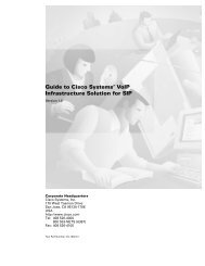
CHAPTER 2. TECHNOLOGY BACKGROUND2.2. PROTOCOLSNetworks, with the focus on <strong>IP</strong> as network layer protocol. The primary goal was to interface multimediacommunication equipment on LANs to the reasonably well-established base on circuit-switchednetworks.The initial version of H.323 was approved by the ITU-T about one year later in June 1996, therebyproviding a basis on which the industry could converge. The initial focus was clearly on local networkenvironments, as QoS mechanisms for <strong>IP</strong>-based wide area networks such as the Internet were not wellestablished at this point. In early 1996 Internet-wide deployment of H.323 was already explicitly includedin the scope as was the aim to support voice-only applications and, thus, the foundations touse H.323 for <strong>IP</strong> <strong>Telephony</strong> were laid. H.323 has continuously evolved towards becoming a technicallysound and functionally rich protocol platform for <strong>IP</strong> telephony applications, the first major additions tothis end being included in H.323 version 2 approved by the ITU-T in January 1998. In September 1999,H.323 version 3 was approved by the ITU-T, incorporating numerous further functional and conceptualextensions to enable H.323 to serve as a basis for <strong>IP</strong> telephony on a global scale and to make it meetrequirements in enterprise environments as well. Moreover, many new enhancements have been introducedinto the H.323 protocol. Version 4 was approved November 17, 2000 and contains enhancementsin a number of important areas, including reliability, scalability, and flexibility. New features help facilitatemore scalable Gateway and MCU solutions to meet the growing market requirements. H.323 hasbeen the undisputed leader in voice, video, and data conferencing on packet networks, and Version 4makes strides to keep H.323 ahead of the competition.2.2.1.1 ScopeAs stated before, the scope of H.323 encompasses multimedia communication in <strong>IP</strong>-based networks,with significant consideration given to gatewaying to circuit-switched networks (particular to ISDNbasedvideo telephony and to PSTN/ISDN/GSM for voice communication).Figure 2.1: Scope and Components defined in H.323H.323 defines a number of functional / logical components as shown in figure Figure 2.1:• Terminal – Terminals are H.323-capable endpoints, which may be implemented in software onworkstations or as stand-alone devices (such as telephones). They are assigned to one or morealiases (e.g. a user’s name / URI) and/or telephone number(s).• Gateway – Gateways interconnect H.323 entities (such as endpoints, MCUs, or other gateways) toother network/protocol environments (such as the telephone network). They are also assignedone or more aliases and/or telephone number(s). The H.323 series of Recommendations providesdetailed specifications for interfacing H.323 to H.320, ISDN/PSTN, and ATM based networks.17
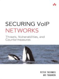
2.2. PROTOCOLS CHAPTER 2. TECHNOLOGY BACKGROUNDRecent work also addresses control and media gateway specifications for telephony trunking networkssuch as SS7/ISUP.• Gatekeeper – The gatekeeper is the core management entity in an H.323 environment. It is, amongother things, responsible for access control, address resolution, and H.323 network (load) managementand provides the central hook to implement any kind of utilization / access policies. AnH.323 environment is subdivided into zones (which may, but need not, be congruent with theunderlying network topology); each zone is controlled by one primary gatekeeper (with optionalbackup gatekeepers). Gatekeepers may also provide value-add, e.g. act as conferencing bridge oroffer supplementary call services. H.323 Gatekeeper can be also equipped with the proxy feature.Such a feature enables the routing through the gatekeeper of the RTP traffic (audio and video) andthe T.120 traffic (data) so no traffic is directly exchanged between endpoints. (it could be considereda kind of <strong>IP</strong> to <strong>IP</strong> gateway that can be used for security and QoS purposes).• Multipoint Controller (MC) – A multipoint controller is a logical entity that interconnects call signalingand conference control channels of two or more H.323 entities in a star topology. MCscoordinate the (control aspects of) media exchange between all entities involved in a conference;they also provide the endpoints with participant lists, exercise floor control, etc. MCs may beembedded in any H.323 entity (terminals, gateways gatekeepers) or implemented as stand-aloneentities. They can be cascaded to allow conferences spanning multiple MCs.• Multipoint Processor (MP) – For multipoint conferences with H.323, an optional Multipoint Processormay be used that receives media streams from the individual endpoints, combines themthrough some mixing/switching technique, and transmits the resulting media streams back to theendpoints.• Multipoint Control Unit (MCU) – In the H.323 world, an MCU simply is a combination of an MCand an MP in a single device. The term originates in the ISDN videoconferencing world whereMCUs were needed to create multipoint conferences out of a set of point-to-point connections.2.2.1.2 Signaling protocolsH.323 resides - similar to the IETF protocols discussed in the next subsection - on top of the basic InternetProtocols (<strong>IP</strong>, <strong>IP</strong> Multicast, TCP, UDP) and can make use of integrated and differentiated services alongwith resource reservation protocols.Figure 2.2: H.323 protocol architecture18
CHAPTER 2. TECHNOLOGY BACKGROUND2.2. PROTOCOLSFor basic call signaling and conference control interactions with H.323, the aforementioned componentscommunicate using three control protocols:• H.225.0 Registration, Admission, and Status (RAS) – The RAS channel is used for communicationbetween H.323 endpoints and their gatekeeper and for some inter-gatekeeper communication.Endpoints use RAS to register with their gatekeeper, to request permission to utilize system resources,to have addresses of remote endpoints resolved, etc. Gatekeepers use RAS to keep trackof the status of their associated endpoints and to collect information about actual resource utilizationafter call termination. RAS provides mechanisms for user / endpoint authentication and callauthorization.• H.225.0 Call Signaling – The call signaling channel is used to signal call setup intention, success,failures, etc. as well as to carry operations for supplementary services (see below). Call signalingmessages are derived from Q.931 (ISDN call signaling); however, simplified procedures and onlya subset of the messages are used in H.323. The call signaling channel is used end-to-end betweencaller and callee and may optionally run through one or more gatekeepers (the call signaling modelsare later described in the Signaling models section).Optimizations: Since version 3 H.225.0 supports the following enhancements:– Multiple Calls - To prevent using a dedicated TCP connection for each call gateways can bebuilt to handle multiple calls on each connection.– Maintain Connection - Similar to Multiple Calls this enhancement shall reduce the need to opennew TCP connections. After the last call has ended the endpoint may decide to maintain theTCP connection to provide a better call setup time for the next call.Primary use of both enhancements is at the communication between servers (Gatekeeper, MCU)or gateways. While in theory both mechanisms were possible before, beginning with H.323v3 themessages contained fields to indicate support for the mechanisms.• H.245 Conference Control – The conference control channel is used to establish and control twoparty calls (as well as multiparty conferences). Its functionality includes determining possiblemodes for media exchange (e.g. select media encoding formats both parties understand) and configuringactual media streams (including exchanging transport addresses to send media streamsto and receive them from). H.245 can be used to carry user input (such as DTMF), it also enablesconfidential media exchange, defines syntax and semantics for multipoint conference operation(see below). Finally, it provides a number of maintenance messages. Also this logical channel mayoptionally run through one or more gatekeeper or directly between caller and called party (pleaserefer to the Signaling models section for details).It should be noted that H.245 is a legacy protocol inherited from the collective work on multimediaconferencing over ATM, PSTN, and other networks. Hence it carries a lot of fields and proceduresthat do not apply to H.323 but make the protocol specification quite heavyweight.Optimizations: The conference control channel is also subject to optimizations. Per default it istransported over an exclusive TCP connection but it may also be tunneled within the signalingconnection (H.245 tunneling). Other optimizations deal with the call setup time. The last chanceto start a H.245 channel is on receipt of the CONNECT message which implies that the first secondsafter the user accepted the call no media is transmitted. H.245 may also start parallel to the setup ofthe H.225 call signaling, which is not really a new feature but another way of dealing with H.245.Vendors often call this Early connect or Early media. Since H.323 V2 it is possible to start a call usinga less powerful but sufficient capability exchange by simply offering possible media channels thatjust have to be accepted. This procedure is called FastConnect or FastStart, requires less round-tripsand is transported over the H.225 channel. After the FastConnect procedure is finished or when itfails the normal H.245 procedures start.A number of extensions to H.323 include mechanisms for more efficient call setup (H.323 Annex E) andreduction of protocol overhead e.g. for simple telephones (SETs, simple endpoint types, H.323 AnnexF).19
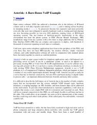
2.2. PROTOCOLS CHAPTER 2. TECHNOLOGY BACKGROUND2.2.1.3 Gatekeeper Discovery and RegistrationA H.323 endpoint usually registers with a gatekeeper that provides basic services like address resolutionfor calling the other endpoints. There are two possibilities for an endpoint to find its gatekeeper:• Multicast discovery - The endpoint sends a gatekeeper request (GRQ) to a well known multicastaddress (224.0.1.41) and port (1718). Receiving gatekeepers may confirm their responsibility forthe endpoint (GCF) or ignore the request.• Configuration - The endpoint knows the <strong>IP</strong> address of the gatekeeper by manual configuration.While there is no need that a gatekeeper request (GRQ) be sent to the preconfigured gatekeepersome products need this protocol step. If a gatekeeper receives a GRQ via unicast it must eitherconfirm (GCF) the request or reject it (GRJ).When trying to discover the gatekeeper via multicast an endpoint may request any gatekeeper or specifythe request by adding a Gatekeeper identifier to the request. Only the gatekeeper that has the requestedidentifier may reply positively. (see figure Figure 2.3)Figure 2.3: Discovery and registration processAfter the endpoint discovers the location of the gatekeeper it tries to register itself (RRQ). Such aregistration includes (among other information):• The addresses of the endpoint - For a terminal this may be the user ids or telephone numbers. Anendpoint may have more than one address. In theory it is possible that addresses belong to differentusers to enable multiple users to share a single phone - in practice this depends on the phonesand gatekeeper implementation.• Prefixes - If the registering endpoint is a gateway it may register number prefixes instead of addresses.• Time to live - An endpoint may request how long the registration shall last. This value can beoverwritten by gatekeeper policies.The gatekeeper checks the requested registration information and confirms the (possibly modified) values(RCF). It may also reject a registration request because of e.g. invalid addresses. In case of a confirmationthe gatekeeper assigns a unique identifier to the endpoint, which shall be used in subsequentrequests to indicate that the endpoint is still registered.Addresses and registrations H.323 defines and utilizes several address types. The one most commonlyused and derived from the PSTN world is the Dialed digit address that is defined as a numberdialed by the endpoint. It does not include further information (e.g. about the dial plan) and needs to beinterpreted by the server. The server might convert the dialed number into a Party Number that includesinformation about the type of number and the dialplan.To provide alphanumeric or name dialing H.323 supports H.323-IDs that represent either usernamesor e-mail like addresses, or the more general approach of URL-ID which represent any kind of URL.20
CHAPTER 2. TECHNOLOGY BACKGROUND2.2. PROTOCOLSUnlike S<strong>IP</strong> addresses, H.323 address can be only registered by one endpoint (per zone) so a call tothat address only resolves to a single endpoint. To call multiple destinations ”simultaneously” in H.323requires a gatekeeper that actively maps a single address to multiple different addresses and tries tocontact them in sequence is required..Updating registrations A registration expires after a defined time and must therefore be refreshedi.e. kept alive by subsequent registrations which include the previsouly assigned endpoint identifier.To reduce the registration overhead of regular registrations H.323 supports KeepAlive registrations thatcontain just the previously assigned endpoint identifier. Of course these registrations may only be sentif the registration information are unchanged.Endpoints requesting the registration of large numbers of addresses would exceed the size of a UDPpacket, so H.323 version4 supports Additive Registration, a mechanism that allows an endpoint to sendmultiple registration requests (RRQ) in which the addresses don’t replace existing registrations but aresubmitted in addition to them.2.2.1.4 Signaling modelsThe call signaling messages and the H.245 control messages may be exchanged either end-to-end betweencaller and called party or through a gatekeeper. Depending on the role the gatekeeper plays inthe call signaling and in the H.245 signaling the H.323 specification foresees three different types ofsignaling models:• Direct signaling, with this signaling model only H.225.0 RAS messages are routed through theGatekeeper while the other logical channel messages are directly exchanged between the two endpoints;• Gatekeeper routed call signaling, with this signaling model H.225.0 RAS and H.225.0 Call signalingmessages are routed through the Gatekeeper while the H.245 Conference control messages aredirectly exchanged between the two endpoints;• Gatekeeper routed H.245 control, H.225.0 RAS and H.225.0 Call signaling an H.245 Conferencecontrol messages are routed through the Gatekeeper and only the media streams are directly exchangedbetween the two endpoints.In the following sub-sections we are going to detail each signaling model. The figures reported in thissection apply both to the use of a single Gatekeeper and to the use of a ”Gatekeeper network”. Since thesignaling model is decided by the endpoint’s Gatekeeper configuration and apply to all the messagessuch Gatekeeper handles, the extensions to the multiple Gatekeeper case is straightforward (simplyapply the definition of the signaling model described in the itemized list above to each Gatekeeper involved)except for the location of zone external targets (described later in Locating zone external targetssection); we decided not to report those message exchange in any of this section figures as it is intendedto remain bounded in the ellipse where the H.323 Gatekeeper is depicted and it is described in the Locatingzone external targets section. Please note that there is no indication about the call termination ineach signaling model sub-section, please refer to Communication phases section for details.Section The Direct signaling model is depicted in Figure 2.4 on the next page. In this model theH.225.0 Call signaling and H.245 Conference control messages are exchanged directly between the callterminals. As shown in the figure, the communication starts with an ARQ (Admission ReQuest) messagesent by the caller (which may be either a Terminal or a Gateway) to the Gatekeeper. The ARQmessage is used by the endpoint to be allowed to access the packet-based network by the Gatekeeper,which either grants the request with an ACF (Admission ConFirm) or denies it with an ARJ (AdmissionReJect), if an ARJ is issued the call is terminated. After this first step the Call signaling part of the callbegins with the transmission of the SET UP message from the caller to the called party. The transportaddress of the SET UP message (and of all the H.225.0 Call signaling messages) is retrieved by the callerfrom the ”destCallSignalAddress” field carried inside the ACF received, in the case of Direct signalingmodel it is the address of the destination endpoint. Upon receiving the SET UP message the called partystarts its H.225.0 RAS procedure with the Gatekeeper, if successful a CONNECT message is sent back tothe caller to indicate acceptance of the call. Before sending the CONNECT message, two other messagesmay be sent from the called party to the caller (those two messages are not depicted in the figure sincewe have reported only mandatory messages):21
2.2. PROTOCOLS CHAPTER 2. TECHNOLOGY BACKGROUND• ALERTING message, this message may be sent by the called user to indicate that called useralerting has been initiated (in everyday terms, the ”phone is ringing”);• CALL PROCEEDING message, this message may be sent by the called user to indicate that requestedcall establishment has been initiated and no more call establishment information will beaccepted.Figure 2.4: Direct signaling modelThe CONNECT message closes the H.225.0 Call signaling part of the call and make the Terminalsstarting the H.245 Conference control one. In such call model the H.245 Conference control messagesare exchanged directly between the two endpoints (the correct ”h245Address” was retrieved from theCONNECT message itself). The procedures started with the H.245 Conference control channel are usedto:• allow the exchange of audiovisual and data capabilities, with the TERMINAL CAPABILITY messages;• request the transmission of a particular audiovisual and data mode, with the LOGICAL CHAN-NEL SIGNALING messages;• to manage the logical channels used to transport the audiovisual and data information;• to establish which terminal is the master terminal and which is the slave terminal for the purposesof managing logical channels, with the MASTER SLAVE DETERMINATION messages;• to carry various control and indication signals;• to control the bit rate of individual logical channels and the whole multiplex, with the MULT<strong>IP</strong>LEXTABLE SIGNALING messages;• to measure the round trip delay, from one terminal to the other and back, with the ROUND TR<strong>IP</strong>DELAY messages.Once the H.245 Conference control messages are exchanged the two endpoints have all the necessaryinformation to open the media streams.22
CHAPTER 2. TECHNOLOGY BACKGROUND2.2. PROTOCOLSGatekeeper routed call signaling model The Gatekeeper routed call signaling model is depicted inFigure 2.5. In this model the H.245 Conference control messages are exchanged directly between thecall termination. As each call, the communication starts with an ARQ (Admission ReQuest) messagesent by the caller to its Gatekeeper. The ARQ message is used by the endpoint to be allowed to accessthe packet-based network by the Gatekeeper, which either grants the request with an ACF (AdmissionConFirm) or denies it with an ARJ (Admission ReJect). After this first step the Call signaling part ofthe call begins with the transmission of the SET UP message from the caller to its Gatekeeper. Thetransport address of the SET UP message (and of all the H.225.0 Call signaling messages) is retrievedby the caller from the ”destCallSignalAddress” field carried inside the ACF received, in the case ofGatekeeper routed call signaling model it is the address of the Gatekeeper itself. The SET UP messageis then forwarded by the Gatekeeper (or by the ”Gatekeeper network”) to the called endpoint. Uponreceiving the SET UP message the called party starts its H.225.0 RAS procedure with its Gatekeeper, ifsuccessful a CONNECT message is sent to indicate acceptance of the call; because of the call model, alsothis message is sent to the called endpoint’s Gatekeeper which is in charge of forwarding it to the callerendpoint (either directly or using the ”Gatekeeper network”). Before sending the CONNECT message,two other messages may be sent from the called party to its Gatekeeper (those two messages are notdepicted in the figure since we have reported only mandatory messages):• ALERTING message, this message may be sent by the called user to indicate that called useralerting has been initiated (in everyday terms, the ”phone is ringing”);• CALL PROCEEDING message, this message may be sent by the called user to indicate that requestedcall establishment has been initiated and no more call establishment information will beaccepted.Figure 2.5: Gatekeeper Routed call signaling modelThe two optional messages listed above are then forwarded by the Gatekeeper (or by the ”Gatekeepernetwork”) to the caller. After receiving the CONNECT message, the caller starts the proceduresH.245 Conference control channel procedures directly with the called party (the correct ”h245Address”was retrieved from the CONNECT message itself). The H.245 Conference control channel procedurescopes are the same detailed above, please refer to Direct signaling model section for details.Gatekeeper routed H.245 control model The Gatekeeper routed H.245 control model is depicted inFigure 2.6 on the next page. In this model only the media streams are exchanged directly between the23
2.2. PROTOCOLS CHAPTER 2. TECHNOLOGY BACKGROUNDcall termination. As each call, the communication starts with an ARQ (Admission ReQuest) messagesent by the caller to its Gatekeeper. The ARQ message is used by the endpoint to be allowed to accessthe packet-based network by the Gatekeeper, which either grants the request with an ACF (AdmissionConFirm) or denies it with an ARJ (Admission ReJect). After this first step the Call signaling part ofthe call begins with the transmission of the SET UP message from the caller to its Gatekeeper. Thetransport address of the SET UP message (and of all the H.225.0 Call signaling messages) is retrievedby the caller from the ”destCallSignalAddress” field carried inside the ACF received, in the case ofGatekeeper routed H.245 control model it is the address of the Gatekeeper itself. The SET UP messageis then forwarded by the Gatekeeper (or by the ”Gatekeeper network”) to the called endpoint. Uponreceiving the SET UP message the called party starts its H.225.0 RAS procedure with its Gatekeeper, ifsuccessful a CONNECT message is sent to indicate acceptance of the call; because of the call model, alsothis message is sent to the called endpoint’s Gatekeeper which is in charge of forwarding it to the callerendpoint (either directly or using the ”Gatekeeper network”). Before sending the CONNECT message,two other messages may be sent from the called party to its Gatekeeper (those two messages are notdepicted in the figure since we have reported only mandatory messages):• ALERTING message, this message may be sent by the called user to indicate that called useralerting has been initiated (in everyday terms, the ”phone is ringing”);• CALL PROCEEDING message, this message may be sent by the called user to indicate that requestedcall establishment has been initiated and no more call establishment information will beaccepted.Figure 2.6: Gatekeeper Routed H.245 control modelThe two optional messages listed above are then forwarded by the Gatekeeper (or by the ”Gatekeepernetwork”) to the caller. After receiving the CONNECT message, the caller starts the H.245 Conferencecontrol channel procedures with its Gatekeeper (the correct ”h245Address” was retrieved fromthe CONNECT message itself). All the H.245 channel messages are then exchanged by the endpointswith their Gatekeeper (or Gatekeepers), it is the Gatekeeper (or ”Gatekeeper network”) which takescare of forwarding them up to the remote endpoint as foreseen by the Gatekeeper routed H.245 controlmodel. The H.245 Conference control channel procedure scopes are the same detailed above, pleaserefer to Direct signaling model section for details.2.2.1.5 Communication PhasesIn a H.323 communication may be identified 5 different phases:24
CHAPTER 2. TECHNOLOGY BACKGROUND2.2. PROTOCOLS• Call set up;• Initial communication and capability exchange;• Establishment of audiovisual communication;• Call services;• Call termination.Call set up Recommendation H.225.0 defines the Call set up messages and procedures here detailed.The recommendation foresees that requests for bandwidth reservation should take place at theearliest possible phase. Differently from other protocols, there is no explicit synchronization betweentwo endpoints during the call setup procedure (two endpoints can send a Setup message each other atexactly the same time). Actions to be taken when problems of synchronization during SET UP messageexchange arise are resolved by the application itself; applications not supporting multiple simultaneouscalls should issue busy signal when they have an outstanding SET UP message, while applications supportingmultiple simultaneous call should issue a busy signal only to the same endpoint to which theysent an outstanding SET UP message. Moreover, an endpoint shall be capable of sending the ALERTINGmessages. Alerting has the meaning that the called party has been alerted of an incoming call (”phoneringing” in the language of the old telephony). Only the ultimate called endpoint shall originate theALERTING message and only when the application has already alerted the user. If a Gateway is involved,the Gateway shall send ALERTING when it receives a ring indication from the Switched CircuitNetwork (SCN). The sending of an ALERTING message is not required if an endpoint can respond to aSET UP message with a CONNECT, CALL PROCEEDING, or RELEASE COMPLETE within 4 seconds.After successfully sending a SET UP message an endpoint can expect to receive either an ALERTING,CONNECT, CALL PROCEEDING, or RELEASE COMPLETE message within 4 seconds after successfultransmission. Finally, to maintain the consistency of the meaning of the CONNECT message betweenpacket based networks and circuit switched networks, the CONNECT message should be sent only if itis certain that the capability exchange will successfully take place and a minimum level of communicationscan be performed.The Call set up phase may have different realizations, basically we can identify different call set up:• Basic call setup when neither endpoint are registered, in this call set up the two endpoints communicatedirectly;• Both endpoints registered to the same gatekeeper, in this call set up the communication is decidedby the signaling model configured on the Gatekeeper;• Only calling endpoint has gatekeeper, in this call set up only the caller sends messages to the Gatekeeperdepending on the signaling models configured while the called party sends the messagesdirectly to the caller endpoint;• Only called endpoint has gatekeeper, in this call set up only the called party sends messages to theGatekeeper depending on the signaling models configured while the caller sends the messagesdirectly to the called endpoint;• Both endpoints registered to different gatekeepers, each of the two endpoints communicate withtheir Gatekeeper depending on the signaling model configured, additional H.225.0 RAS messagesmay be exchanged between gatekeeper in order to retrieve location information (see Locating zoneexternal targets section for more details);• Call set up with Fast connect procedure, in this call set up the media channels are established usingeither the ”Fast Connect” procedure. The Fast Connect procedure speeds up the establishment ofa basic point-to-point call (only one round-trip message exchange is needed), enabling immediatemedia stream delivery upon call connection. The Fast connect procedure is started if the callingendpoint initiates it by sending a SETUP message containing the fastStart element (to advice itis going to use the Fast Connect procedure). Such element contains, among the other things, asequence of all of the parameters necessary to immediately open and begin transferring media onthe channels. Fast Connect procedure may be refused by the called endpoint (motivations maybe either because it wants to use features requiring use of H.245 or because it does not implementit). Fast Connect procedure may be refused with any H.225.0 Call signaling message up to and includingthe CONNECT one. Refusing the Fast Connect procedure (or not initiating it) requires that25
2.2. PROTOCOLS CHAPTER 2. TECHNOLOGY BACKGROUNDH.245 procedures be used for capabilities exchange and opening of media channels. Moreover, theFast Connect procedure allows to have more information for the scope of H.323/S<strong>IP</strong> gatewaying(further details to be found in Chapter 4);• Call setup via gateways, when a gateway is involved the call setup between it and the networkendpoint is the same as the endpoint-to-endpoint call set up;• Call setup with an MCU, when an MCU is involved all endpoints exchange call signaling with theMCU (and with the interested Gatekeepers if any). No changes are foreseen between an endpointand the MCU call set up since it proceeds the same as the endpoint-to-endpoint;• Broadcast call setup, this kind of call set up follows the procedures defined in RecommendationH.332.Initial communication and capability exchange After exchanging call setup messages, the endpointsshall, if they plan to use H.245, establish the H.245 Control Channel. The H.245 Control Channelis used for the capability exchange and to open the media channels. The H.245 Control channel proceduresshall either not be started or closed if CONNECT does not arrive (an H.245 Control channel can beopened on reception of ALERTING or CALL PROCEEDING messages, too) or an endpoint sends RE-LEASE COMPLETE. H.323 endpoints shall support the capabilities exchange procedure of H.245. TheH.245 TERMINALCAPABILITYSET message is used for endpoint system capabilities exchange. Thismessage shall be the first H.245 message sent. Master-slave determination procedure of H.245 has tobe supported by H.323 compliant endpoints as a must. In cases of multipoint conferencing (MC) capabilityis present in more than one endpoint, the master-slave determination is used for determiningwhich MC will play an active role. The H.245 Control channel procedure also provides master-slavedetermination for opening bi-directional channels for data. After Terminal Capability Exchange hasbeen initiated, master-slave determination procedure (consisting of either MASTERSLAVEDETERMI-NATION or MASTERSLAVEDETERMINATIONACK) has to be started as the first H.245 Conferencecontrol procedure. Upon failure of initial capability exchange or master-slave determination proceduresa maximum of two retries shall be performed before the endpoint passes to the Call Termination phase.Normally, after successful completion of the requirements of this phase, the endpoints shall proceeddirectly to Establishment of audiovisual communication phase.Encapsulation of H.245 messages within H.225.0 Call signaling messages Encapsulation of H.245messages inside H.225.0 Call signaling messages instead of establishing a separate H.245 channel ispossible in order to save resources, synchronize call signaling and control, and reduce call setup time.This process is named as ”encapsulation” or ”tunneling” of H.245 messages. This procedure allows theterminal to copy the encoded H.245 message using one structure inside the data of the Call SignalingChannel. If tunneling is used, any H.225.0 Call signaling message may contain one or more H.245messages. If there is no need of sending an H.225.0 Call signaling message when an H.245 message hasto be transmitted, a FACILITY message shall be sent detailing (with appropriate fields inside) the reasonof such a message.Establishment of audiovisual communication The Establishment of audiovisual communicationshall follow the procedures of Recommendation H.245. Open logical channels for the various informationstreams are opened using the H.245 procedures. The audio and video streams are transported usingan unreliable protocol while data communications are transported using a reliable protocol. The transportaddress that the receiving endpoint has assigned to a specific logical channel (audio, video or data)is transported by the OPENLOGICALCHANNELACK message (an example is given in Figure 2.7 onthe facing page). That transport address is used to transmit the information stream associated with thatlogical channel.Call services When the call is active, the terminal may request additional call services, among thosewe report here on the Bandwidth changes services and on the Supplementary services. As regards asBandwidth changes services, during a conference, the endpoints or Gatekeeper (if involved) may, at anytime, request an increase or decrease in the call bandwidth. If the aggregate bit rate of all transmitted andreceived channels does not exceed the current call bandwidth then an endpoint may change the bit rateof a logical channel without requesting a bandwidth change. After requesting for bandwidth change, the26
CHAPTER 2. TECHNOLOGY BACKGROUND2.2. PROTOCOLSFigure 2.7: OPENLOGICALCHANNELACK message contentendpoint shall wait for confirmation prior to actually changing the bit rate (confirmation usually comesfrom the Gatekeeper). Asking call bandwidth changes is performed using a BANDWIDTH CHANGEREQUEST (BRQ) message, if the request is not accepted, a BANDWIDTH CHANGE REJECT (BRJ)message is returned to endpoint. If the request is accepted, a BANDWIDTH CHANGE CONFIRM(BCF) is sent back to the endpoint. As regards as Supplementary services, support for them is optional.The H.450-Series of Recommendations describe a method of providing Supplementary Services in theH.323 environment. Figure 2.8 reports some of the supplementary services defined so far and theirRecommendation number.Figure 2.8: Supplementary services of the H.450-SeriesCall termination A call may be terminated either by both endpoint or by the Gatekeeper. Calltermination is defined using the following procedure:• video should be terminated after a complete picture and then all logical channels for video closed;27
2.2. PROTOCOLS CHAPTER 2. TECHNOLOGY BACKGROUND• data transmission should be terminated and then all logical channels for data closed;• audio transmission should be terminated and then all logical channels for audio closed;• the H.245 ENDSESSIONCOMMAND message (H.245 Control Channel) should be sent by the endpoint/Gatekeeper,this message indicates that the call has to be disconnected, then the H.245 messagetransmission should be terminated;• the ENDSESSIONCOMMAND message should be sent back to the sending endpoint and then theH.245 Control Channel should be closed;• a RELEASE COMPLETE message should be sent closing the Call Signaling channel if this is stillopen;An endpoint receiving ENDSESSIONCOMMAND message does not need to receive it back again afterreplying to it in order to clear a call. Terminating a call within a conference does not mean the allconference needs to be terminated. In order to terminate a conference an H.245 message (DROPCON-FERENCE) is used, then the MC should terminate the calls with the endpoint as described above.A call may be terminated differently depending on the Gatekeeper presence and on the party issuingthe call termination:• Call clearing without a Gatekeeper - No further action is required.• Call clearing with a Gatekeeper - The Gatekeeper needs to be informed about the Call termination.After RELEASE COMPLETE is sent, an H.225.0 DISENGAGE REQUEST (DRQ) message shouldbe sent by each endpoint to its Gatekeeper. A Disengage Confirm (DCF) message is sent back tothe endpoints to acknowledge the reception.• Call clearing issued by the Gatekeeper - A call may be terminated by the Gatekeeper by sending aDRQ to an endpoint. The procedure described above for Call termination should be immediatelyfollowed by the endpoint up to the RELEASE COMPLETE message included,then a reply to theGatekeeper should be sent using a DCF message. The other endpoint should follow the sameCall termination procedures upon receiving the ENDSESSIONCOMMAND message. Moreover,if a multipoint conference is taking place, in order to close the entire conference, the Gatekeepershould send a DRQ to each endpoint in the conference.2.2.1.6 Locating zone external targetsWhen calling an address that is registered at the same gatekeeper as the caller, the case - the gatekeeperjust needs to look up its internal tables to resolve the target address. Complexity enters the picture ifthe destination address is registered with another gatekeeper. While Chapter 7 on page 153, “Globaltelephony integration” will cover this topic in more detail, the most basic mechanism H.323 providesshall be explained here.A gatekeeper may explicitly request the resolution of an address from other gatekeepers. On receiptof an request to call an address that the gatekeeper has no registration, it can send out a location request(LRQ) to other gatekeepers (see figure Figure 2.9 on the next page). The receiving gatekeeper - assumingit knows the address - will reply with the Transport Service Access Point (a combination of <strong>IP</strong> address andportnumber) of either the requested address or its own call signaling TSAP.A location request can be sent via Unicast or Multicast. If sent via Multicast, only the gatekeeperthat can resolve the address shall reply. If a gatekeeper receives a unicast LRQ, it shall either confirm orreject the request.This mechanism can be used to have a list of peer gatekeeper to ask in parallel or sequentially. It isalso possible to assign a domain suffix or number prefix to each peer so that an address with a matchingnumber prefix of a neighbouring institution will result in a request to the gatekeeper of that institution.By defining default peers one could also build a hierarchy of gatekeepers (Again, see Chapter 7 onpage 153, “Global telephony integration” for further details.)28
CHAPTER 2. TECHNOLOGY BACKGROUND2.2. PROTOCOLSFigure 2.9: External address resolution using LRQs2.2.1.7 Sample Call ScenarioFigure 2.10 on the next page depicts an example of an inter-zone call setup using H.323 with one gatekeeper(A) using direct signaling while the other uses routed signaling. The caller in zone A contacts itsgatekeeper to ask for permission to call the called party in zone B (1). Gatekeeper of zone A confirmsthis request and provides the caller with the address of zone B’s gatekeeper (2).1 The caller establishes acall signaling channel (and subsequently / in parallel the conference control channel) to the gatekeeperof zone B (3), who determines the location of the called party and forwards the request to the calledparty (4).The called party explicitly confirms with its gatekeeper that it is allowed to accept the call (5, 6) and,if so, alerts the recipient of the call, returns an alerting indication and (once the receiving user picks upthe call) eventually an indication of successful connection setup back to the caller (7, 8). In (parallel to)this exchange, capability negotiation and media stream configuration take place. When the setup hascompleted, both parties start sending media streams directly to each other.2.2.1.8 Additional (Call) ServicesIt is well known from our daily interaction with PBXes, that telephony service comprises far more thanjust call setup and teardown: n-way conferencing and various supplementary services (such as calltransfer, call waiting, etc.) are available. Similar features - at least the more commonly known and usedones - need to be provided by <strong>IP</strong> telephony systems as well to be accepted by customers. Additional callservices in H.323 can be grouped into three categories:• Conferencing – H.323 inherently supports multipoint tightly-coupled conferencing - i.e. conferenceswith access control, optional support for conference chairs, and close synchronization of conferencestate among all participants - from the outset: through the concept of a Multipoint Controllerand an optional Multipoint Processor. While control is centralized in the MC, in theory data exchangemay be either via <strong>IP</strong> multicast, multi-unicast (i.e. peer-wise fan-out between endpointswithout MP), or through an MP. (Practically there seems to be no H.323 equipment supportingmedia multicast.) The distribution mode may be selected per-media and per endpoint peer and iscontrolled by the MC.• ”Broadcast conferencing” – H.323 also provides an interface to support large loosely-coupled conferencesas are frequently used in the Mbone to multicast seminars, events, etc. In this case, the MCdefines session description (using the Session Description Protocol, SDP, see below) for the H.323media sessions (which have to operate using multicast) and announces this description by somemeans (e.g. the Session Announcement Protocol, SAP). Details are defined in ITU-T H.332.29
2.2. PROTOCOLS CHAPTER 2. TECHNOLOGY BACKGROUNDFigure 2.10: Sample H.323 Call Setup Scenario• Supplementary Services – H.323 provides a variety of supplementary services with additional onescontinuously being defined. While some services can be accomplished using the basic H.323 specifications,the H.450.x Recommendations define a framework (derived from QSIG, the ECMA/ISO/ETSIstandard for supplementary service signaling in PBXes) and a number of services (call transfer, calldiversion, call hold, call park & pickup, call waiting, message waiting indication, call completion).Further extensions for supplementary services and other functional enhancements are on the way. Inparticular, an HTTP-based extension framework is being defined at the time of writing to enable rapidintroduction of new services without the need for standardization.2.2.1.9 H.235 SecurityThe H.235 recommendation defines elements of security for H.323. This includes:• AuthenticationAuthentication can be achieved by using a shared secret (password) or digital signatures. TheRAS messages include a token that was generated using either the shared secret or the signature.A receiving entity authenticate the sender by comparing the received token with a self generatedtoken.• Message IntegrityIntegrity is achieved by generating a password based checksum over the message.• PrivacyMechanisms are provided to setup encryption on the media streams. They must be used in conjunctionwith the H.245 protocol and employ DES, Triple DES or RC2 - the use of SRTP is notsupported yet (in H.235v2).Those mechanisms are grouped into the so called Security Profiles, where the Baseline Security Profileprovides authentication and message integrity making it suitable for subscription based environmentsand the Voice Encryption Profile that provides confidential end-to-end media channels.30
CHAPTER 2. TECHNOLOGY BACKGROUND2.2. PROTOCOLS2.2.1.10 Protocol ProfilesH.323 has its origin - as mentioned before - in the area of multimedia conferencing. This implies thata vast number of options are available which are not necessary for simply providing telephony services.The T<strong>IP</strong>HON project of the European Telecommunication Standards Institute (ETSI) has defineda <strong>Telephony</strong> Profile for H.323 that specifies which combination of options should be implemented.Similarly, H.323 contains a security framework (H.235) that describes a collection of algorithms andprotocol mechanisms but lacks - because of international political constraints - a precise specification ofa mandatory baseline. This is accounted for by the ETSI T<strong>IP</strong>HON security profile: this specification fillsin the gaps and provides the foundation for inter operable implementations.In summary, it can be said that the H.323 family of standards provides a mature basis for commercialproducts in the field of <strong>IP</strong> telephony. While the details of the protocol are often dominated by theirlegacy from various earlier ITU protocols, there is an active effort to profile and simplify the protocol toreduce the complexity.2.2.2 S<strong>IP</strong>2.2.2.1 Purpose of S<strong>IP</strong>S<strong>IP</strong> stands for Session Initiation Protocol. It is an application-layer control protocol which has beendeveloped and designed within the IETF . The protocol has been designedwith easy implementation, good scalability, and flexibility in mind.The specification is available in form of several RFCs, the most important one is RFC3261 which contains the core protocol specification. The protocolis used for creating, modifying, and terminating sessions with one or more participants. By sessionswe understand a set of senders and receivers that communicate and the state kept in those sendersand receivers during the communication. Examples of a session can include Internet telephone calls,distribution of multimedia, multimedia conferences, distributed computer games, etc.S<strong>IP</strong> is not the only protocol that the communicating devices will need. It is not meant to be a generalpurpose protocol. Purpose of S<strong>IP</strong> is just to make the communication possible, the communication itselfmust be achieved by another means (and possibly another protocol). Two protocols that are most oftenused along with S<strong>IP</strong> are RTP and SDP. RTP protocol is used to carry the real-time multimedia data(including audio, video, and text), the protocol makes it possible to encode and split the data into packetsand transport such packets over the Internet. Another important protocol is SDP–Session DescriptionProtocol, which is used to describe and encode capabilities of session participants. Such a descriptionis then used to negotiate the characteristics of the session so that all the devices can participate (thatincludes, for example, negotiation of codecs used to encode media so all the participants will be able todecode it, negotiation of transport protocol used and so on).S<strong>IP</strong> has been designed in conformance with the Internet model. It is an end-to-end oriented signalingprotocol which means, that all the logic is stored in end devices (except routing of S<strong>IP</strong> messages). State isalso stored in end-devices only, there is no single point of failure and networks designed this way scalewell. The price that we have to pay for the distributiveness and scalability is higher message overhead,caused by the messages being sent end-to-end.It is worth mentioning that the end-to-end concept of S<strong>IP</strong> is a significant divergence from regularPSTN (Public Switched Telephone Network) where all the state and logic is stored in the network andend devices (telephones) are very primitive. Aim of S<strong>IP</strong> is to provide the same functionality that thetraditional PSTNs have, but the end-to-end design makes S<strong>IP</strong> networks much more powerful and opento the implementation of new services that can be hardly implemented in the traditional PSTNs.S<strong>IP</strong> is based on HTTP protocol. The HTTP protocol inherited format of message headers fromRFC822 . HTTP is probably the most successful andwidely used protocol in the Internet. S<strong>IP</strong> tries to combine the best of the both. In fact, HTTP can beclassified as a signaling protocol too, because user agents use the protocol to tell a HTTP server in whichdocuments they are interested in. S<strong>IP</strong> is used to carry the description of session parameters, the descriptionis encoded into a document using SDP. Both protocols (HTTP and S<strong>IP</strong>) have inherited encodingof message headers from RFC822 . The encoding hasproven to be robust and flexible over the years.S<strong>IP</strong> URI S<strong>IP</strong> entities are identified using S<strong>IP</strong> URI (Uniform Resource Identifier). A S<strong>IP</strong> URI hasform of sip:username@domain, for instance, sip:joe@company.com. As we can see, S<strong>IP</strong> URI consists31
2.2. PROTOCOLS CHAPTER 2. TECHNOLOGY BACKGROUNDof username part and domain name part delimited by @ (at) character. S<strong>IP</strong> URIs are similar to e-mailaddresses, it is, for instance, possible to use the same URI for e-mail and S<strong>IP</strong> communication, such URIsare easy to remember.2.2.2.2 S<strong>IP</strong> Network ElementsAlthough in the simplest configuration it is possible to use just two user agents that send S<strong>IP</strong> messagesdirectly to each other, a typical S<strong>IP</strong> network will contain more than one type of S<strong>IP</strong> elements. Basic S<strong>IP</strong>elements are user agents, proxies, registrars, and redirect servers. We will briefly describe them in thissection.Note that the elements, as presented in this section, are often only logical entities. It is often profitableto co-locate them together, for instance, to increase the speed of processing, but that depends on aparticular implementation and configuration.User Agents Internet end points that use S<strong>IP</strong> to find each other and to negotiate a session characteristicsare called user agents. User agents usually, but not necessarily, reside on a user’s computerin form of an application–this is currently the most widely used approach, but user agents can be alsocellular phones, PSTN gateways, PDAs, automated IVR systems and so on.User agents are often referred to as User Agent Server (UAS) and User Agent Client (UAC). UAS andUAC are logical entities only, each user agent contains a UAC and UAS. UAC is the part of the user agentthat sends requests and receives responses. UAS is the part of the user agent that receives requests andsends responses.Because a user agent contains both UAC and UAS, we often say that a user agent behaves like aUAC or UAS. For instance, caller’s user agent behaves like UAC when it sends an INVITE requests andreceives responses to the request. Called party’s user agent behaves like a UAS when it receives theINVITE and sends responses.But this situation changes when the called party decides to send a BYE and terminate the session.In this case the called party’s user agent (sending BYE) behaves like UAC and the caller’s user agentbehaves like UAS.Figure 2.11: UAC and UASFigure 2.11 shows three user agents and one stateful forking proxy. Each user agent contains UACand UAS. The part of the proxy that receives the INVITE from the caller in fact acts as a UAS. When forwardingthe request statefully the proxy creates two UACs, each of them is responsible for one branch.32
CHAPTER 2. TECHNOLOGY BACKGROUND2.2. PROTOCOLSIn our example called party B picked up and later when he wants to tear down the call it sends aBYE. At this time the user agent that was previously UAS becomes a UAC and vice versa.Proxy Servers In addition to that S<strong>IP</strong> allows creation of an infrastructure of network hosts calledproxy servers. User agents can send messages to a proxy server. Proxy servers are very important entitiesin the S<strong>IP</strong> infrastructure. They perform routing of a session invitations according to invitee’s currentlocation, authentication, accounting and many other important functions.The most important task of a proxy server is to route session invitations “closer” to called party. Thesession invitation will usually traverse a set of proxies until it finds one which knows the actual locationof the called party. Such a proxy will forward the session invitation directly to the called party and thecalled party will then accept or decline the session invitation.There are two basic types of S<strong>IP</strong> proxy servers–stateless and stateful.Stateless Servers Stateless servers are simple message forwarders. They forward messages independentlyof each other. Although messages are usually arranged into transactions (see Section 2.2.2.4 onpage 38), stateless proxies do not take care of transactions.Stateless proxies are simple, but faster than stateful proxy servers. They can be used as simple loadbalancers, message translators and routers. One of drawbacks of stateless proxies is that they are unableto absorb re-transmissions of messages and perform more advanced routing, for instance, forking orrecursive traversal.Stateful Servers Stateful proxies are more complex. Upon reception of a request, stateful proxiescreate a state and keep the state until the transaction finishes. Some transactions, especially those createdby INVITE, can last quite long (until called party picks up or declines the call). Because stateful proxiesmust maintain the state for the duration of the transactions, their performance is limited.The ability to associate S<strong>IP</strong> messages into transactions gives stateful proxies some interesting features.Stateful proxies can perform forking, that means upon reception of a message two or more messageswill be sent out.Stateful proxies can absorb re-transmissions because they know, from the transaction state, if theyhave already received the same message (stateless proxies cannot do the check because they keep nostate).Stateful proxies can perform more complicated methods of finding a user. It is, for instance, possibleto try to reach user’s office phone and when he does not pick up then the call is redirected to his cellphone. Stateless proxies can’t do this because they have no way of knowing how the transaction targetedto the office phone finished.Most S<strong>IP</strong> proxies today are stateful because their configuration is usually very complex. They oftenperform accounting, forking, some sort of NAT traversal aid and all those features require a statefulproxy.Proxy Server Usage A typical configuration is that each centrally administered entity (a company,for instance) has it’s own S<strong>IP</strong> proxy server which is used by all user agents in the entity. Let’s supposethat there are two companies A and B and each of them has it’s own proxy server. Figure 2.12 on thefollowing page shows how a session invitation from employee Joe in company A will reach employeeBob in company B.User Joe uses address sip:bob@b.com to call Bob. Joe’s user agent does not know how to routethe invitation itself but it is configured to send all outbound traffic to the company S<strong>IP</strong> proxy serverproxy.a.com. The proxy server figures out that user sip:bob@b.com is in a different company so it willlook up B’s S<strong>IP</strong> proxy server and send the invitation there. B’s proxy server can be either pre-configuredat proxy.a.com or the proxy will use DNS SRV records to find B’s proxy server. The invitation reachesproxy.bo.com. The proxy knows that Bob is currently sitting in his office and is reachable through phoneon his desk, which has <strong>IP</strong> address 1.2.3.4, so the proxy will send the invitation there.Registrar We mentioned that the S<strong>IP</strong> proxy at proxy.b.com knows current Bob’s location but haven’tmentioned yet how a proxy can learn current location of a user. Bob’s user agent (S<strong>IP</strong> phone) must registerwith a registrar. The registrar is a special S<strong>IP</strong> entity that receives registrations from users, extractsinformation about their current location (<strong>IP</strong> address, port and username in this case) and stores the informationinto location database. Purpose of the location database is to map sip:bob@b.com to something33
2.2. PROTOCOLS CHAPTER 2. TECHNOLOGY BACKGROUNDFigure 2.12: Session Invitationlike sip:bob@1.2.3.4:5060. The location database is then used by B’s proxy server. When the proxy receivesan invitation for sip:bob@b.com it will search the location database. It finds sip:bob@1.2.3.4:5060and will send the invitation there. A registrar is very often a logical entity only. Because of their tightcoupling with proxies, registrars are usually co-located with proxy servers.Figure 2.13 on the next page shows a typical S<strong>IP</strong> registration. A REGISTER message containingAddress of Record sip:jan@iptel.org and contact address sip:jan@1.2.3.4:5060 where 1.2.3.4 is <strong>IP</strong> addressof the phone, is sent to the registrar. The registrar extracts this information and stores it into the locationdatabase. If everything went well then the registrar sends a 200 OK response to the phone and theprocess of registration is finished.Each registration has a limited life span. Expires header field or expires parameter of Contact headerfield determines for how long is the registration valid. The user agent must refresh the registrationwithin the life span otherwise it will expire and the user will become unavailable.Redirect Server The entity that receives a request and sends back a reply containing a list of thecurrent location of a particular user is called redirect server. A redirect server receives requests and looksup the intended recipient of the request in the location database created by a registrar. It then createsa list of current locations of the user and sends it to the request originator in a response within S<strong>IP</strong> 3xxredirection responses class.The originator of the request then extracts the list of destinations and sends another request directlyto them. Figure 2.14 on page 36 shows a typical redirection.2.2.2.3 S<strong>IP</strong> MessagesCommunication using S<strong>IP</strong> (often called signaling) comprises of series of messages. Messages can betransported independently by the network. Usually they are transported in a separate UDP datagrameach. Each message consist of “first line”, message header, and message body. The first line identifiestype of the message. There are two types of messages–requests and responses. Requests are usually usedto initiate some action or inform recipient of the request of something. Replies are used to confirm thata request was received and processed and contain the status of the processing.A typical S<strong>IP</strong> request looks like this:INVITE sip:7170@iptel.org S<strong>IP</strong>/2.034
CHAPTER 2. TECHNOLOGY BACKGROUND2.2. PROTOCOLSFigure 2.13: Registrar OverviewVia: S<strong>IP</strong>/2.0/UDP 195.37.77.100:5040;rportMax-Forwards: 10From: "jiri" ;tag=76ff7a07-c091-4192-84a0-d56e91fe104fTo: Call-ID: d10815e0-bf17-4afa-8412-d9130a793d96@213.20.128.35CSeq: 2 INVITEContact: User-Agent: Windows RTC/1.0Proxy-Authorization: Digest username="jiri", realm="iptel.org",algorithm="MD5", uri="sip:jiri@bat.iptel.org",nonce="3cef753900000001771328f5ae1b8b7f0d742da1feb5753c",response="53fe98db10e1074b03b3e06438bda70f"Content-Type: application/sdpContent-Length: 451v=0o=jku2 0 0 IN <strong>IP</strong>4 213.20.128.35s=sessionc=IN <strong>IP</strong>4 213.20.128.35b=CT:1000t=0 0m=audio 54742 RTP/AVP 97 111 112 6 0 8 4 5 3 101a=rtpmap:97 red/8000a=rtpmap:111 SIREN/16000a=fmtp:111 bitrate=16000a=rtpmap:112 G7221/16000a=fmtp:112 bitrate=24000a=rtpmap:6 DVI4/16000a=rtpmap:0 PCMU/8000a=rtpmap:4 G723/8000a=rtpmap: 3 GSM/8000a=rtpmap:101 telephone-event/8000a=fmtp:101 0-1635
2.2. PROTOCOLS CHAPTER 2. TECHNOLOGY BACKGROUNDFigure 2.14: S<strong>IP</strong> RedirectionThe first line tells us that this is INVITE message which is used to establish a session. The URI onthe first line–sip:7170@iptel.org is called Request URI and contains URI of the next hop of the message.In this case it will be host iptel.org.A S<strong>IP</strong> request can contain one or more Via header fields which are used to record path of the request.They are later used to route S<strong>IP</strong> responses exactly the same way. The INVITE message contains just oneVia header field which was created by the user agent that sent the request. From the Via field we can tellthat the user agent is running on host 195.37.77.100 and port 5060.From and To header fields identify initiator (caller) and recipient (called party) of the invitation (justlike in SMTP where they identify sender and recipient of a message). From header field contains a tagparameter which serves as a dialog identifier and will be described in Section 2.2.2.5 on page 38.Call-ID header field is a dialog identifier and its purpose is to identify messages belonging to thesame call. Such messages have the same Call-ID identifier. CSeq is used to maintain order of requests.Because requests can be sent over an unreliable transport that can re-order messages, a sequence numbermust be present in the messages so that recipient can identify re-transmissions and out of order requests.Contact header field contains <strong>IP</strong> address and port on which the sender is awaiting further requestssent by called party. Other header fields are not important and will be not described here.Message header is delimited from message body by an empty line. Message body of the INVITErequest contains a description of the media type accepted by the sender and encoded in SDP.S<strong>IP</strong> Requests We have described what an INVITE request looks like and said that the request isused to invite a called party to a session. Other important requests are:• ACK–This message acknowledges receipt of a final response to INVITE. Establishing of a sessionutilizes 3-way hand-shaking due to asymmetric nature of the invitation. It may take a while beforethe called party accepts or declines the call so the called party’s user agent periodically re-transmitsa positive final response until it receives an ACK (which indicates that the caller is still there andready to communicate).• BYE–Bye messages are used to tear down multimedia sessions. A party wishing to tear down asession sends a BYE to the other party.• CANCEL–Cancel is used to cancel not yet fully established session. It is used when the calledparty has not replied with a final response yet but the caller wants to abort the call (typically whena called party does not respond for some time).• REGISTER–Purpose of REGISTER request is to let registrar know of current user’s location. Informationabout current <strong>IP</strong> address and port on which a user can be reached is carried in REGISTER36
CHAPTER 2. TECHNOLOGY BACKGROUND2.2. PROTOCOLSmessages. Registrar extracts this information and puts it into a location database. The databasecan be later used by S<strong>IP</strong> proxy servers to route calls to the user. Registrations are time-limited andneed to be periodically refreshed.The listed requests usually have no message body because it is not needed in most situations (but canhave one). In addition to that many other request types have been defined but their description is outof the scope of this document.S<strong>IP</strong> Responses When a user agent or proxy server receives a request it sends a reply. Each requestmust be replied to except ACK requests which trigger no replies.A typical reply looks like this:S<strong>IP</strong>/2.0 200 OKVia: S<strong>IP</strong>/2.0/UDP 192.168.1.30:5060;received=66.87.48.68From: sip:sip2@iptel.orgTo: sip:sip2@iptel.org;tag=794fe65c16edfdf45da4fc39a5d2867c.b713Call-ID: 2443936363@192.168.1.30CSeq: 63629 REGISTERContact: ;q=0.00;expires=120Server: Sip EXpress router (0.8.11pre21xrc (i386/linux))Content-Length: 0Warning: 392 195.37.77.101:5060 "Noisy feedback tells:pid=5110 req_src_ip=66.87.48.68 req_src_port=5060 in_uri=sip:iptel.orgout_uri=sip:iptel.org via_cnt==1"As we can see, responses are very similar to the requests, except for the first line. The first line ofresponse contains protocol version (S<strong>IP</strong>/2.0), reply code, and reason phrase.The reply code is an integer number from 100 to 699 and indicates type of the response. There are 6classes of responses:• 1xx are provisional responses. A provisional response is response that tells to its recipient thatthe associated request was received but result of the processing is not known yet. Provisionalresponses are sent only when the processing does not finish immediately. The sender must stopre-transmitting the request upon reception of a provisional response.Typically proxy servers send responses with code 100 when they start processing an INVITE anduser agents send responses with code 180 (Ringing) which means that the called party’s phone isringing.• 2xx responses are positive final responses. A final response is the ultimate response that the originatorof the request will ever receive. Therefore final responses express result of the processingof the associated request. Final responses also terminate transactions. Responses with code from200 to 299 are positive responses that means that the request was processed successfully and accepted.For instance a 200 OK response is sent when a user accepts invitation to a session (INVITErequest).A UAC may receive several 200 messages to a single INVITE request. This is because a forkingproxy (described later) can fork the request so it will reach several UAS and each of them willaccept the invitation. In this case each response is distinguished by the tag parameter in To headerfield. Each response represents a distinct dialog with unambiguous dialog identifier.• 3xx responses are used to redirect a caller. A redirection response gives information about theuser’s new location or an alternative service that the caller might use to satisfy the call. Redirectionresponses are usually sent by proxy servers. When a proxy receives a request and does not wantor can’t process it for any reason, it will send a redirection response to the caller and put anotherlocation into the response which the caller might want to try. It can be the location of anotherproxy or the current location of the called party (from the location database created by a registrar).The caller is then supposed to re-send the request to the new location. 3xx responses are final.• 4xx are negative final responses. a 4xx response means that the problem is on the sender’s side. Therequest could not be processed because it contains bad syntax or cannot be fulfilled at that server.37
2.2. PROTOCOLS CHAPTER 2. TECHNOLOGY BACKGROUND• 5xx means that the problem is on server’s side. The request is apparently valid but the server failedto fulfill it. Clients should usually retry the request later.• 6xx reply code means that the request cannot be fulfilled at any server. This response is usuallysent by a server that has definitive information about a particular user. User agents usually send a603 Decline response when the user does not want to participate in the session.In addition to the response class the first line also contains reason phrase. The code number is intended tobe processed by machines. It is not very human-friendly but it is very easy to parse and understand bymachines. The reason phrase usually contains a human-readable message describing the result of theprocessing. A user agent should render the reason phrase to the user.The request to which a particular response belongs is identified using the CSeq header field. Inaddition to the sequence number this header field also contains method of corresponding request. Inour example it was REGISTER request.2.2.2.4 S<strong>IP</strong> TransactionsAlthough we said that S<strong>IP</strong> messages are sent independently over the network, they are usually arrangedinto transactions by user agents and certain types of proxy servers. Therefore S<strong>IP</strong> is said to be a transactionalprotocol.A transaction is a sequence of S<strong>IP</strong> messages exchanged between S<strong>IP</strong> network elements. A transactionconsists of one request and all responses to that request. That includes zero or more provisionalresponses and one or more final responses (remember that an INVITE might be answered by more thanone final response when a proxy server forks the request).If a transaction was initiated by an INVITE request then the same transaction also includes ACK, butonly if the final response was not a 2xx response. If the final response was a 2xx response then the ACKis not considered part of the transaction.As we can see this is quite asymmetric behavior–ACK is part of transactions with a negative finalresponse but is not part of transactions with positive final responses. The reason for this separation isthe importance of delivery of all 200 OK messages. Not only that they establish a session, but also 200OK can be generated by multiple entities when a proxy server forks the request and all of them must bedelivered to the calling user agent. Therefore user agents take responsibility in this case and retransmit200 OK responses until they receive an ACK. Also note that only responses to INVITE are retransmitted!S<strong>IP</strong> entities that have notion of transactions are called stateful. Such entities usually create a stateassociated with a transaction that is kept in the memory for the duration of the transaction. Whena request or response comes, a stateful entity tries to associate the request (or response) to existingtransactions. To be able to do it it must extract a unique transaction identifier from the message andcompare it to identifiers of all existing transactions. If such a transaction exists then its state gets updatedfrom the message.In the previous S<strong>IP</strong> RFC2543 the transaction identifierwas calculated as hash of all important message header fields (that included To, From, Request-URI and CSeq). This proved to be very slow and complex, during interoperability tests such transactionidentifiers used to be a common source of problems.In the new RFC3261 the way of calculating transactionidentifiers was completely changed. Instead of complicated hashing of important header fields aS<strong>IP</strong> message now includes the identifier directly. Branch parameter of Via header fields contains directlythe transaction identifier. This is significant simplification, but there still exist old implementations thatdon’t support the new way of calculating of transaction identifier so even new implementations have tosupport the old way. They must be backwards compatible.Figure 2.15 on the facing page shows what messages belong to what transactions during a conversationof two user agents.2.2.2.5 S<strong>IP</strong> DialogsWe have shown what transactions are, that one transaction includes INVITE and it’s responses andanother transaction includes BYE and its responses when a session is being torn down. But we feel thatthose two transactions should be somehow related–both of them belong to the same dialog. A dialogrepresents a peer-to-peer S<strong>IP</strong> relationship between two user agents. A dialog persists for some time38
CHAPTER 2. TECHNOLOGY BACKGROUND2.2. PROTOCOLSFigure 2.15: S<strong>IP</strong> Transactionsand it is very important concept for user agents. Dialogs facilitate proper sequencing and routing ofmessages between S<strong>IP</strong> endpoints.Dialogs are identified using Call-ID, From tag, and To tag. Messages that belong to the same dialogmust have these fields equal. We have shown that CSeq header field is used to order messages, in factit is used to order messages within a dialog. The number must be monotonically increased for eachmessage sent within a dialog otherwise the peer will handle it as out of order request or retransmission.In fact, the CSeq number identifies a transaction within a dialog because we have said that requests andassociated responses are called transaction. This means that only one transaction in each direction canbe active within a dialog. One could also say that a dialog is a sequence of transactions. Figure 2.16 on thenext page extends Figure 2.15 to show which messages belong to the same dialog.Some messages establish a dialog and some do not. This is used to explicitly express the relationshipof messages and also to send messages that are not related to other messages outside a dialog. That iseasier to implement because user agent don’t have to keep the dialog state.For instance, INVITE message establishes a dialog, because it will be later followed by BYE requestwhich will tear down the session established by the INVITE. This BYE is sent within the dialog establishedby the INVITE.But if a user agent sends a MESSAGE request, such a request does not establish any dialog. Anysubsequent messages (even MESSAGE) will be sent independently of the previous one.Dialogs Facilitate Routing We have said that dialogs are also used to route the messages betweenuser agents, let’s describe this a little bit.Let’s suppose that user sip:bob@a.com wants to talk to user sip:pete@b.com. He knows S<strong>IP</strong> addressof the called party (sip:pete@b.com) but this address does not say anything about current location of theuser–i.e. the caller does not know to which host to send the request. Therefore the INVITE request willbe sent to a proxy server.The request will be sent from proxy to proxy until it reaches one that knows current location ofthe called party. This process is called routing. Once the request reaches the called party, the calledparty’s user agent will create a response that will be sent back to the caller. called party’s user agentwill also put Contact header field into the response which will contain the current location of the user.The original request also contained Contact header field which means that both user agents know thecurrent location of the peer.39
2.2. PROTOCOLS CHAPTER 2. TECHNOLOGY BACKGROUNDFigure 2.16: S<strong>IP</strong> DialogBecause the user agents know location of each other, it is not necessary to send further requests toany proxy–they can be sent directly from user agent to user agent. That’s exactly how dialogs facilitaterouting.Further messages within a dialog are sent directly from user agent to user agent. This is a significantperformance improvement because proxies do not see all the messages within a dialog, they are used toroute just the first request that establishes the dialog. The direct messages are also delivered with muchsmaller latency because a typical proxy usually implements complex routing logic. Figure 2.17 on thenext page contains an example of a message within a dialog (BYE) that bypasses the proxies.Dialog Identifiers We have already shown that dialog identifiers consist of three parts, Call-Id,From tag, and To tag, but it is not that clear why are dialog identifiers created exactly this way and whocontributes which part.Call-ID is so called call identifier. It must be a unique string that identifies a call. A call consists of oneor more dialogs. Multiple user agents may respond to a request when a proxy along the path forks therequest. Each user agent that sends a 2xx response establishes a separate dialog with the caller. All suchdialogs are part of the same call and have the same Call-ID.From tag is generated by the caller and it uniquely identifies the dialog in the caller’s user agent.To tag is generated by a called party and it uniquely identifies, just like From tag, the dialog in thecalled party’s user agent.This hierarchical dialog identifier is necessary because a single call invitation can create several dialogsand caller must be able to distinguish them.2.2.2.6 Typical S<strong>IP</strong> ScenariosThis section gives a brief overview of typical S<strong>IP</strong> scenarios that usually make up the S<strong>IP</strong> traffic.Registration Users must register themselves with a registrar to be reachable by other users. Aregistration comprises a REGISTER message followed by a 200 OK sent by registrar if the registrationwas successful. Registrations are usually authorized so a 407 reply can appear if the user did not providevalid credentials. Figure 2.18 on the facing page shows an example of registration.40
CHAPTER 2. TECHNOLOGY BACKGROUND2.2. PROTOCOLSFigure 2.17: S<strong>IP</strong> TrapezoidFigure 2.18: REGISTER Message FlowSession Invitation A session invitation consists of one INVITE request which is usually sent toa proxy. The proxy sends immediately a 100 Trying reply to stop re-transmissions and forwards therequest further.All provisional responses generated by called party are sent back to the caller. See 180 Ringingresponse in the call flow. The response is generated when called party’s phone starts ringing.A 200 OK is generated once the called party picks up the phone and it is retransmitted by the calledparty’s user agent until it receives an ACK from the caller. The session is established at this point.Session Termination Session termination is accomplished by sending a BYE request within dialogestablished bye INVITE. BYE messages are sent directly from one user agent to the other unless a proxyon the path of the INVITE request indicated that it wishes to stay on the path by using record routing(see Section 2.2.2.6 on the next page.Party wishing to tear down a session sends a BYE request to the other party involved in the session.The other party sends a 200 OK response to confirm the BYE and the session is terminated. SeeFigure 2.20 on page 43, left message flow.41
2.2. PROTOCOLS CHAPTER 2. TECHNOLOGY BACKGROUNDFigure 2.19: INVITE Message FlowRecord Routing All requests sent within a dialog are by default sent directly from one user agentto the other. Only requests outside a dialog traverse S<strong>IP</strong> proxies. This approach makes S<strong>IP</strong> networkmore scalable because only a small number of S<strong>IP</strong> messages hit the proxies.There are certain situations in which a S<strong>IP</strong> proxy need to stay on the path of all further messages.For instance, proxies controlling a NAT box or proxies doing accounting need to stay on the path of BYErequests.Mechanism by which a proxy can inform user agents that it wishes to stay on the path of all furthermessages is called record routing. Such a proxy would insert Record-Route header field into S<strong>IP</strong> messageswhich contain address of the proxy. Messages sent within a dialog will then traverse all S<strong>IP</strong> proxies thatput a Record-Route header field into the message.The recipient of the request receives a set of Record-Route header fields in the message. It mustmirror all the Record-Route header fields into responses because the originator of the request also needsto know the set of proxies.Left message flow of Figure 2.20 on the next page show how a BYE (request within dialog establishedby INVITE) is sent directly to the other user agent when there is no Record-Route header field in themessage. Right message flow show how the situation changes when the proxy puts a Record-Routeheader field into the message.Event Subscription And Notification The S<strong>IP</strong> specification has been extended to support a generalmechanism allowing subscription to asynchronous events. Such evens can include S<strong>IP</strong> proxy statisticschanges, presence information, session changes and so on.The mechanism is used mainly to convey information on presence (willingness to communicate) of42
CHAPTER 2. TECHNOLOGY BACKGROUND2.2. PROTOCOLSFigure 2.20: BYE Message Flow (With and without Record Routing)users. Figure 2.21 on the following page show the basic message flow.A user agent interested in event notification sends a SUBSCRIBE message to a S<strong>IP</strong> server. The SUB-SCRIBE message establishes a dialog and is immediately replied by the server using 200 OK response.At this point the dialog is established. The server sends a NOTIFY request to the user every time theevent to which the user subscribed changes. NOTIFY messages are sent within the dialog establishedby the SUBSCRIBE.Note that the first NOTIFY message in Figure 2.21 on the next page is sent regardless of any eventthat triggers notifications.Subscriptions–as well as registrations–have limited life span and therefore must be periodically refreshed.Instant Messages Instant messages are sent using MESSAGE request. MESSAGE requests do notestablish a dialog and therefore they will always traverse the same set of proxies. This is the simplestform of sending instant messages. The text of the instant message is transported in the body of the S<strong>IP</strong>request.2.2.3 Media Gateway Control ProtocolsIn a traditional telephone network, the infrastructure consists of large telephone switches which interconnectwith each other to create the backbone network and which also connect to customer premiseequipment (PBXs, telephones). While the internal network today is based upon digital communication,links to customers may be either analog (PSTN) or digital (ISDN). The links to customers are shared betweencall signaling (for dialing, invocation of supplementary services, etc.) and carriage of voice/data.In the backbone, dedicated (virtual) links interconnecting switches are reserved for call signaling (defactocreating a dedicated network of its own) whereas voice/data traffic is carried on separate links. TheSignaling System No. 7 (SS7) or variants of it are used as the call signaling protocol between switches;this protocol is used to route voice/data channels across the backbone network by instructing eachswitch on the way which incoming ”line” is to be forwarded to which outgoing ”line” and which otherprocessing (such as simple voice compression, in-band signaling detection to customer premise equipment,etc.) is to be applied. Voice/data channels themselves are plain bit pipes identified by roughly atrunk and line identifier at each switch.43
2.2. PROTOCOLS CHAPTER 2. TECHNOLOGY BACKGROUNDFigure 2.21: Event Subscription And NotificationA similar construction is now considered by a number of telcos for <strong>IP</strong>-based backbone networks thatmay successively replace parts of their overall switched network infrastructure, as depicted in figure 3.7.Instead of voice switches, <strong>IP</strong> routers are used to build up a backbone network - which employs <strong>IP</strong> routing,possibly MPLS, and, most likely, some explicit form of QoS support to carry voice and data packetsfrom any point in the network to any other. In contrast to voice switches, this does not require explicitconfiguration of the individual routers per voice connection; rather, only the entry and exit points needto be configured with each others’ addresses so that they know where to send their voice/data packetsto. Two types of gateways are used at the edges of the <strong>IP</strong> network to connect to the conventionaltelephone network: signaling gateways to convert SS7 signaling into <strong>IP</strong>-based call control (which maymake use of H.323 or S<strong>IP</strong> or simply provide a transport to carry SS7 signaling in <strong>IP</strong> packets [SIGTRAN])and media gateways that perform voice transcoding.1 Some central entity (actually, probably a numberof co-operating entities) forms the intelligent core of the backbone: the Media Gateway Controller(s).They interpret call signaling and decide how to route calls, provide supplementary services, etc. Havingdecided on how a call is to be established, they inform the (largely passive and ”dumb”) mediagateways at the edges (ingress and egress gateways) how and where to transmit the voice packets. TheMedia Gateway Controllers also re-configure the Gateways in case of any changes in the call, invocationof supplementary services, etc. The media gateways may be capable of detecting invocation of controlfeatures in the media channel (e.g. through DTMF tones) and notify the Media Gateway Controller(s)which then initiate the appropriate actions.A number of protocols have been defined for communication between Media Gateway Controllersand media gateways: initial versions were developed by multiple camps, some of which merged tocreate the Media Gateway Control Protocol (MGCP), the only one of the proprietary protocols that isdocumented as an Informational RFC (RFC 2705). An effort was launched to make the two remainingcamps cooperate and develop a single protocol to be standardized which resulted in work groups in theITU-T (rooted in Study Group 16, Q.14) and in the IETF (Media Gateway Control, MEGACO WG). Theprotocol being jointly developed is referred to as H.248 in the ITU-T and as MEGACO in the IETF.One particular protocol extension currently discussed in the IETF is the definition of a protocol forcommunication with an <strong>IP</strong> telephone at the customer premises that fits seamlessly with the Media GatewayControl architecture. Such a telephone would be a rather simple entity essentially capable of transmittingand receiving events and reacting to them while the call services are provided directly by thenetwork infrastructure.44
CHAPTER 2. TECHNOLOGY BACKGROUND2.2. PROTOCOLSFigure 2.22: Instant Messages2.2.4 Proprietary Signaling ProtocolsToday nearly every vendor that offers Vo<strong>IP</strong> products uses his own Vo<strong>IP</strong> protocol - e.g. Cisco’s Skinnyor Siemens’s CorNet. They were invented by the vendors to be able to provide more or specific supplementaryservices in the Voice over <strong>IP</strong> world, in order to offer customers all the features they alreadyknow from their classic PBX. The enterprise solutions usually feature such a proprietary protocol at thecure and provide minimalistic support for a standardized protocol (until now usually H.323) with onlybasic call functionality.Giving detailed information about those protocols is out of the scope of this document - and usuallydifficult to provide for most protocols are not publicly available.2.2.5 Real Time Protocol (RTP) and Real Time Control Protocol (RTCP)RTP and RTCP are the transport protocols used for <strong>IP</strong> telephony media streams. Both of them were definedin RFC1889 ; the former as a protocol to carrydata that has real-time properties, the latter to monitor the quality of service and to convey informationabout the participants in on-going session. The services provided by the RTP protocol are:• identification of the carried information (audio and video codecs);• checking packet in-order delivery and, if necessary, re-ordering the out-of-sequence blocks;• transport of the coder/decoder synchronization information;• monitoring of the information delivery.The RTP protocol uses the underlying User Datagram Protocol (UDP) to manage multiple connectionsbetween two entities and to check for data integrity (checksum). An important point to stress is thatRTP neither provides any mean to have a guaranteed QoS nor assumes the underlying network deliversordered packets.The RTCP protocol uses the same protocols as RTP to periodically send control packets to all sessionparticipants. Every RTP channel using port number N has its own RTCP protocol channel with portnumber equal to N+1. The services provided by the RTCP are:45
2.2. PROTOCOLS CHAPTER 2. TECHNOLOGY BACKGROUNDFigure 2.23: Application Scenario for Media Gateway Control Protocols• giving a feedback on the data quality distribution, feedback used to keep control of the activecodecs;• transporting a constant identifier for the RTP source (CNAME), used by the receiver to link a SSRCidentifier and its source to synchronize audio and video data;• advertising the number of session participants, number used to adjust the RTP data transmissionrate;• carrying session control information, used to identify the session participants.In the next two subsection we are going to describe the RTP and RTCP header and the different types ofpacket those two protocol use.2.2.5.1 RTP HeaderFigure 2.24 on the facing page shows the RTP header. The first 12 bytes are present in all the RTP packets,the last bytes containing the CSRC (Contributing SouRCe) identifiers list is present only when a mixeris crossed (with mixer we refer to a system which receives two or more RTP flows, combines them andforwards the resulting flow).The header fields are here detailed:• version (V - 2 bits), contains the RTP protocol version;• padding (P - 1 bit), if set to 1 then the packet contains one or more additional bytes after the datafield;• extension (X - 1 bit), if set to 1 then the header is followed by an extension;• CSRC count (CC - 4 bits), contains the CSRC identifiers number which follow the header;• marker (M - 1 bit), application available field;• payload type (PT - 7 bits), identifies the data field format of the RTP packet and determines itsinterpretation by the application;46
CHAPTER 2. TECHNOLOGY BACKGROUND2.2. PROTOCOLSFigure 2.24: RTP Header• sequence number (16 bits), value incremented by one for each RTP packet sent, used by the receiverto detect losses and to determine the right sequence;• RTP timestamp (32 bits), is the sampling time of the first RTP byte, used for synchronization andjitter calculation;• SSRC ID (32 bits), identifies the synchronization source, chosen randomly within a RTP session;• CSRC ID list (from 0 to 15*32 bits), optional field identifying the sources which contribute to thedata in the packet, the number of the CSRC IDs is written in the CSRC count field.2.2.5.2 RTCP packet types and formatIn order to transport the session control information, the RTCP foresees a number of packet types:• SR, Sender Report, to carry the information sent by the transmitters, to give notice to the otherparticipants on the control information they should receive (number of bytes, number of packets,etc.);• RR, Receiver Report, to carry the statistics of the session participants which are not active transmitters;• SDES, Source DESscription, to carry the session description (including the CNAME identifier);• BYE, to notify the intention of leaving the session;• AAP, to carry application specific functions, used by experimental use of new applications.Every RTCP packet begins with a fixed part similar to the one of the RTP ones, such part is then followedby structural element of variable length. More than one RTCP packet may be linked together to builda COMPOUND PACKET. Moreover, in order to maximize the statistics resolution, the SR and the RRpacket types are to be sent more often than the other packet types.47
Chapter 3<strong>IP</strong> <strong>Telephony</strong> Scenarios3.1 IntroductionUsing the technology background terminology defined in the previous chapter, we will now describe themost interesting scenarios in building an <strong>IP</strong> telephony infrastructure. The following scenarios addresstopics with increasing complexity (from a long-distance least cost routing scenario to a fully-integrated<strong>IP</strong> telephony - videoconferencing one). The aim of this chapter is to provide the reader with both ahigh level overview of each scenario and motivations on why they are to be deployed. Each scenario isanalyzed from the user needs point of view and is described architecturally giving an implementationexample.3.2 Scenario 1: Long-distance least cost routingThis scenario is likely to be adopted by enterprises with high-cost call volumes. Traditionally, separatelinks have been used for transferring voice and data between two sites (see Figure 3.1 on the next page),thus making it simple to achieve a reduction in costs by establishing accounts with a lower-cost longdistancecarrier. Voice over <strong>IP</strong> offers an alternative solution for this kind of problem: existing enterprisedata networks (using <strong>IP</strong> protocol) may be used to carry long-distance voice traffic to certain destinations,thus lowering the total costs (see Figure 3.2 on the following page). A combination of lower-cost,long-distance carrier and Voice over <strong>IP</strong> voice-data integration is seen as the most cost-effective solutionin this area. This requires the routing of calls to the lowest-cost network, depending on time of day anddestination and it is referred to as Least-Cost Routing (LCR). In order to achieve greater savings, it routescalls to destinations by re-dialing them through the lowest cost alternative carrier / terminator available.A basic scenario’s architecture (depicted in Figure 3.3 on page 51) shall be able to handle all calls originatingfrom the enterprise network. Elements needed to deploy this scenario are: terminals (both <strong>IP</strong>and PSTN) and the necessary Gateways to route the call from the <strong>IP</strong> network to the ISDN/PSTN/GSMand vice versa; other elements like MCUs or servers may be optionally present, but are not required.The hybrid solution, including both traditional processing of calls over PSTN/ISDN and an additional<strong>IP</strong> <strong>Telephony</strong> part, results in this detailed architecture:The features such an architecture may provide can be basically summarized in:• Call routing by time of day and day of the week, allowing selection of the best rates for specifictime periods.• Call routing by destination, allowing selection of the best rates depending on the destination ofthe call.• Number modification, allowing dial-string manipulation of the original number dialed, to facilitateprefix-based routing.• Class of Service management, allowing management of individual extensions with differentiatedclass of service, to give that higher level of service to users who need it.49
3.3. SCENARIO 2: ALTERNATIVES TO LEGACY PBX SYSTEMS CHAPTER 3. <strong>IP</strong> TELEPHONY SCENARIOSFigure 3.1: Traditional separation of data and telephony between locationsFigure 3.2: Integration of data and telephony between locations3.2.1 Least Cost Routing - An implementation exampleA company with head-quarter offices and multiple branch-office sites in Europe makes daily long distancecalls to contact customers located all over the world. Since many telephone carriers provide cheaptelephone rates depending on geographic areas, the competitive telephone market may be used to reducecommunication costs. A first solution would require the maintenance of an up-to-date table, basedon the savings depending on the time of day and destination. The problems arising from this solution inthe maintenance and distribution of this table to the employees are evident. Moreover, it is certain thatnot every employee will remember to dial the extra digits for each appropriate prefix, both because it istime-consuming and as a result of negligence. Therefore, an engineering process is needed to mantainthe costs low. Least-Cost Routing is the solution to this kind of problems, as it allows the telephone systemto automatically route the long distance call to the most economical telephony carrier / network,saving money on the long distance bill and reduceing the employee’s effort in making calls.In order to put such solution in place, the company needs to deploy a set of Gateways in the locationswhere branch offices are located, to take advantage of the integration of data and telephony linksbetween locations as depicted in Figure 3.2. This can result in savings from both calls located in thearea of the branch offices, as well as office-to-office calls, taking advantage of the data network connectingthe company’s sites. Note that in this case, a distributed routing table has to be implemented, inorder to facilitate control by the system administrator, who may wish to update it anytime changes inlong-distance rates occur.3.3 Scenario 2: Alternatives to legacy PBX systemsTraditionally, institutions and companies are equipped with a PBX on each one of its sites. Telephonesare wired to the PBX, which supplies them with power. The PBX handles all intelligence and routes callsto the PSTN over trunks (E1, T1, J1, ISDN30 etc).One of the most economically feasible deployments of <strong>IP</strong> <strong>Telephony</strong> currently is in the area of installingvoice over <strong>IP</strong> as a replacement of inter-building PSTN connections within one company, or even50
CHAPTER 3. <strong>IP</strong> TELEPHONY SCENARIOS 3.3. SCENARIO 2: ALTERNATIVES TO LEGACY PBX SYSTEMSFigure 3.3: Least cost routing architecturethe complete replacement of the PBX phone system itself, along with its terminals.This chapter first describes the scenarios in which <strong>IP</strong> phones can be deployed in a peer-to-peer fashionwithout additional control entities in the network. This case is only covered briefly because itspractical use is limited.Then a more common scenario will be described, where <strong>IP</strong> <strong>Telephony</strong> is introduced in the existingtelephony infrastructure. The legacy PBX is still functional in this scenario, and voice calls can not onlycarried over regular PSTN trunks, but also over <strong>IP</strong> backbones.The last scenario describes the total replacement of a PBX infrastructure by <strong>IP</strong> <strong>Telephony</strong> equipment.3.3.1 Scenario 2a: <strong>IP</strong>-Phones without a PBX systemThe simplest case of <strong>IP</strong> <strong>Telephony</strong> is making a point-to-point call between <strong>IP</strong> Phones. To place a call, thecalling party needs to know the <strong>IP</strong> address of the called party, or its DNS entry.For mission-critical cases, such as a commercial company or an institutional phone system, this isan awkward method. Moreover, it is not possible to make a call to a regular telephone within theinstitution or to the PSTN, because no Vo<strong>IP</strong>-to-PSTN gateway is available. Also, common features likecentral address books, call forwarding services, etc. are harder to integrate with the phone terminal. Ifthe destination is unreachable, nothing useful can be done with the call, like redirecting it to a voicemailservice, etc. This setup is therefore only recommended for testing purposes.Call setup is very simple, when using either H.323, or S<strong>IP</strong> or any variations of these protocols. Sincethe calling party directly enters the <strong>IP</strong> address of the destination, call initiation signaling is sent directlyto that <strong>IP</strong> address. If the terminal is functional, it will process the signaling and the called party willbe prompted to pick up the phone. When that happens, the call is setup, a codec is negotiated and thevoice stream will start, until signaling that terminates the call is exchanged.51
3.3. SCENARIO 2: ALTERNATIVES TO LEGACY PBX SYSTEMS CHAPTER 3. <strong>IP</strong> TELEPHONY SCENARIOSFigure 3.4: Legacy PBX which trunks to the PSTNFigure 3.5: <strong>IP</strong>-Phone to <strong>IP</strong>-Phone without PBX3.3.2 Scenario 2b: Integration of Vo<strong>IP</strong> with legacy PBX systemsThis scenario allows the coexistence and intercommunication of the institutional conventional telephonynetwork (conventional phones connected to PBX) and the local <strong>IP</strong> telephony network. The scenario issuitable when the local <strong>IP</strong> telephony network is constructed gradually in an institution that already hasa conventional telephony network. In a later stage, the conventional telephony network and the PBXcan be totally replaced by the <strong>IP</strong> telephony network, thus converging to Scenario 2c.For example, in order to provide for smooth transition, it might be worthwhile to buy a gateway withtwo ISDN PRI interfaces (or just with one interface and borrow the second interface for the transitionperiod). One interface is connected to the PSTN and the second one to PBX. During the transition periodGateway performs also call routing between PSTN and the old PBX and vice versa providing a smoothtransition in the meanwhile.In this chapter we give an overview of options for interconnecting a PBX to a Voice Gateway (VoGW).These options also apply to Scenario 1. More technical details for individual interfaces are given inChapter 4.The choice of a particular interface between a PBX and a VoGW depends on required functionality,availability of interconnection ports on both sides and also on cost constraints. Interfaces can be dividedinto analog and digital. The former include a 2-wire U-interface with subscriber loop and various typesof E&M interfaces. The latter include an E1/CAS trunk with MFC-R2 signaling and ISDN with DSS1or QSIG signaling. Giving technical details about the trunks and interfaces mentioned above is outsidethe scope of this Chapter, refer to Chapter 4 for further details. On the other hand, technical peoplewho want to understand this kind of scenario may benefit from a discussion of the advantages andshortcomings of individual interfaces, which are summarized in the following list:• Subscriber loop - Suitable when conventional phones should be connected directly to VoGW (VoiceGateWay) via an FXS interface - an FXS interface connects directly to a standard telephone andsupplies ring, voltage, and dial tone, but can also be used for PBX interconnection. A disadvantageis that when calling inward towards the PBX, an extension number can be dialed only as DTMF(Dual-Tone Multifrequency) suffix, after a call is established and is already accounted for. Thistype of interface is usually a low-cost solution.• E&M interfaces - E&M is commonly explained as Ear and Mouth or recEive and transMit. Allowsextension dialing before the conversation begins. Requires a special interface card for the PBX, butif the PBX is already equipped with this card, this can also be a low-cost solution.52
CHAPTER 3. <strong>IP</strong> TELEPHONY SCENARIOS 3.3. SCENARIO 2: ALTERNATIVES TO LEGACY PBX SYSTEMSFigure 3.6: Integration of <strong>IP</strong>-<strong>Telephony</strong> with legacy PBX system• E1/CAS trunk with MFC-R2 signaling - CAS (Channel Associated Signaling) exists in many variantsthat operate over analog and digital interfaces. The advantage of a digital interface is its abilityto transfer the identification of the calling party, which is important for detailed accounting. Thisis the first digital solution that was used, which was later mostly replaced by ISDN interfaces.Requires special interface cards on both sides of the interconnection, and it is a rather expensivesolution.• ISDN with DSS1 signaling - In addition to calling party identification, supplementary services areavailable such as Call Waiting, Do not disturb, etc. Can be used with a BRI interface (Basic RateInterface, up to 2 simultaneous calls) or PRI interface (Primary Rate Interface, up to 30 simultaneouscalls). The interface card is usually already in place on modern PBXs. The PRI interface iseconomically preferable when more than 8 channels (4xBRI) are required.• ISDN with QSIG signaling - QSIG signaling supports more supplementary services, such as Callcompletion, Path replacements, etc. However, QSIG uses proprietary features of the PBX fromparticular manufacturers and is therefore suitable only for corporate networks, where <strong>IP</strong> telephonyis used to interconnect PBXs in company branches.3.3.3 Scenario 2c: Full replacement of legacy PBX systemsIt is only in greenfield situations, when building a telephony service from scratch, or when an existingPBX is fully depreciated, that <strong>IP</strong> <strong>Telephony</strong> can be considered as a complete replacement alternative toa traditional PBX.The design of an <strong>IP</strong>BX system involves a couple of choices.3.3.3.1 Intelligent vs. simple terminals<strong>IP</strong>BXes can support terminals in two ways: either through analogue ports that support analogue terminals,or through <strong>IP</strong> only. The latter implies that the terminals are intelligent devices, including animplementation of signaling functions. Since intelligence in <strong>IP</strong> phones is built-in anyway, these terminalsare often equipped with interactive screens and other sophisticated functions. As a result, theequipment is expensive and requires to be provided with power, either externally or by Power-over-Ethernet. A feature that most of these advanced terminals support is pass-through of Ethernet packets,so that a single wall outlet can be used for both <strong>IP</strong> <strong>Telephony</strong> and computer data.53
3.3. SCENARIO 2: ALTERNATIVES TO LEGACY PBX SYSTEMS CHAPTER 3. <strong>IP</strong> TELEPHONY SCENARIOSFigure 3.7: <strong>IP</strong>-<strong>Telephony</strong> fully replacing PBX3.3.3.2 SignallingThough the choice among H.323, S<strong>IP</strong> and proprietary protocols seems a purely technical one, it hasimplications on the interoperability with future expansions, inter-department trunking and the deploymentof new advanced features, like messaging, etc. It is wise to require that a supplier complies to atleast one of the open standards.3.3.3.3 Inter-department trunkingThe choice of a full <strong>IP</strong>-based institutional voice architecture does not automatically lead to a specificsolution for connecting geographically separated locations. The cookbook examines the options for thiscase in the Least-Cost Routing section.The inter-departmental architecture also involves a choice of whether to break out local calls at localPSTN trunks, or to centralize all PSTN trunking on one of the locations of the institution. This choicedepends on the tariff structure that the public operator(s) offer for centralized break out, as well as thevolume of calls that have a local public destination as compared to long-distance public and privatedestined calls.3.3.3.4 Legacy functionalityTraditional PBXes have the advantage that long-recognized needs have been incorporated throughdecades of development in their functionality. These important features need to be implemented bythe <strong>IP</strong> <strong>Telephony</strong> architecture as well, if it is to become a competitive solution. The most elementary ofthese are:• Emergency call handling to public emergency numbers (911, 112 etc)• Public dialplan routing (regular numbers, blocking/routing of premiumnumbers etc)• Integration with public wireless telephony• Voice/data integration and call distribution for call center/help desk department• Support for beeper systems• Support for private wireless telephony• Support for elevator phones54
CHAPTER 3. <strong>IP</strong> TELEPHONY 3.4. SCENARIOS 3: INTEGRATION OF VO<strong>IP</strong> AND VIDEOCONFERENCING3.3.3.5 Wireless Vo<strong>IP</strong>With at least three manufacturers currently presenting wireless <strong>IP</strong> terminals that can use IEEE 802.11b(Wi-Fi) wireless data communication, a new aspect for Vo<strong>IP</strong> is emerging. Where DECT has a strong positionin the wireless PBX market, it can be expected that institutions with Wi-Fi networks in place, willwant to reuse this infrastructure for their wireless telephony network, obtaining similar consolidationadvantages, as in the fixed <strong>IP</strong> telephony case. Wireless <strong>IP</strong> phones are equally intelligent as their fixed<strong>IP</strong> equivalents, but are different on the Ethernet level. The usual issues in wireless data communicationsare battery autonomy, portability, coverage, etc. Current developments show that manufacturersof public network mobile phones like GSM are planning to include Wireless Vo<strong>IP</strong> into their terminals.This would enable seamless roaming from public mobile telephony networks to the campus wirelessenvironment, potentially reducing costs when calling locally on campus.3.3.3.6 IssuesSince the field of <strong>IP</strong>BXes is rapidly emerging, many features that are known in the traditional PBXes arequickly adopted. Additionaly, new issues arise as data networks develop. An example is the introductionof network access control by IEEE 802.1X. This standard forces equipment to first authenticate at aRADIUS server before accessing the network. All equipment on 802.1X enabled network ports shouldbe 802.1X enabled as well. With the adoption of 802.1X, the vendors are announcing terminals thatsupport this standard as well.A similar situation holds for VLANs. In case a network administrator chooses to put <strong>IP</strong> telephonesin a different VLAN from PC (groups) and the <strong>IP</strong> telephones are in pass-through configuration, theyshould support VLAN trunking. This feature is also appearing in the market.3.4 Scenario 3: Integration of Vo<strong>IP</strong> and VideoconferencingWhen referring to Vo<strong>IP</strong> and <strong>IP</strong> telephony the main focus is on voice services, which may be misleadingregarding the support of video. <strong>IP</strong> telephony standards (see Chapter 2) do have the capabilities ofsignaling and are able to initiate multimedia communications. This scenario details how voice over <strong>IP</strong>technologies / standards and videoconferencing solutions may be seamlessly integrated. The goal isto provide the users with a global architecture derived from <strong>IP</strong> telephony standards, giving videoconferencingsystems the chance of becoming widely used and adopted. Videoconferencing systems havethe purpose of facilitating meetins of remote participants, and to support the illusion that they are allsharing the same space and communicating as if they were in the same room. Perfect videoconferencingsessions are achieved when the technology is no longer noticeable. Even though the perceived qualityof video and audio plays the most important role, there are a number of other factors influencing theperception of successful videoconferencing:• accessibility of the system, the system should be accessible on a broad area giving users the easiestway of communicating without worrying on how to join a conference or how to find reachabilityinformation on the party to call;• value-added services, such as data/application sharing and voice mail, are only two examples ofvalue-added services which are not feasible with classic telephony systems, yet may improve thequality experienced by the user;• interoperability among different technologies: the system should be transparent to different technologiesin order to give the users the chance of having seamless connectivity.In order to describe the possible integration scenario of Vo<strong>IP</strong> and Videoconferencing we need to examinewhich are the possible applications related to the Videoconferencing scenario. Basic use of videoconferencingsystems relates to meetings (special cases of meetings are classroom and collaboration meetings);more specific applications may be developed on top of the basic functionality, with enanched options.Here we cite a set of the most significant applications:• Telecommuting - Telecommuting is a broad term referring to corporate employees who interactelectronically with corporate resources and people. Extensions of the term refer to the individualinteraction and collaboration that takes place between home-based consultants and inter-companybusiness partners.55
3.4. SCENARIO 3: INTEGRATION OF VO<strong>IP</strong> AND VIDEOCONFERENCINGCHAPTER 3. <strong>IP</strong> TELEPHONY SCENARIOS• Telemedicine - Videoconferencing solutions delivering high-quality video images to remote medicalspecialists. Specialized videoconferencing devices may be required to enable high-quality videocontents not available with the standard videoconferencing systems.• Distance Learning - Video lectures, remote guest speakers invitation to a classroom and privatelessons to groups of students located in different locations are some of the educational processesrequiring the use of videoconferencing tools.• Customer Services - Videoconferencing-based customer services enable call center operators to bemore effective while interacting with customers.• Justice services - Many legal systems introduce the use of videoconferencing to enable police officersto attend legal proceedings. This optimizes the time police need to spend in courthouses.• Virtual/Remote Laboratories - Remote laboratories allow researchers to share advanced appliancesusing existing network infrastructure. In the Telemedicine, specialized devices may be required toenable high-quality video contents (not available with the standard videoconferencing systems) tobe transmitted; moreover, special considerations apply when such interaction modes are considered.A successful integration scenario would require, on the application side, application specific devices (forbasic meetings, simple desktop conferencing equipment may be enough) to deliver the content to theend-user and, on the technical side, servers (to build a global architecture accessible by all group users),gateways (to provide interoperability with different access technologies and different <strong>IP</strong> telephony protocols),conference bridges and multipoint conferencing units (to provide capabilities for multipointconferencing).3.4.1 Integrating Voice and Videoconferencing over <strong>IP</strong> - an exampleIn order to give the reader an understanding of a complex scenario, such as the integration of voice andvideoconferencing over <strong>IP</strong>, we describe here an example actually implemented at the SURFnet offices inThe Netherlands. An integrated voice and video environment is a setup based on H.323 components(endpoints, MCU and gateway), a Cisco CallManager (using the Skinny protocol), and a PBX. Thereforethis is also an example of scenario 2b (Integration with legacy PBX systems). Figure 3.8 on the next pagegives an overview of the components and how they are connected.The goal of the integration of voice and videoconferencing over <strong>IP</strong> was to make possible to referdirectly to the user without knowing his location and what terminal is actually using. When someonecontacts the user by any means (PSTN or H.323 of H.320), the call should be completed by reachingany device the user may have operational. The components necessary to establish such an integratedinfrastructure are:• a PBX, connected to the PSTN, in this case a Philips Sopho, to handle all incoming regular voicecalls;• a H.323 gateway, in this case a Radvision L2W (LAN to WAN H.323) gateway, on the one sideconnected to the PBX (by 2 ISDN lines) and on the other side to the local <strong>IP</strong> network;• a H.323 gatekeeper, in this case the build-in gatekeeper of the Radvision gateway, to route all callson the <strong>IP</strong> network, including making decisions when to route the call off-net (to the PSTN throughthe PBX);• a Callmanager, in this case a Cisco Callmanager, being the gatekeeper to performing PBX-likefunctions for the <strong>IP</strong>-phones;• endstations, being the user’s terminal(s).The terminals used here are:• <strong>IP</strong> phones, in this case Selsius and Cisco <strong>IP</strong> phones, registered on the Callmanager;• H.323 videoconferencing stations, in this case VCON EscortPro boards in PCs with Meetingpoint4.6 and Polyspan Viewstations (128 and FX), registered at the H.323 gatekeeper;56
CHAPTER 3. <strong>IP</strong> TELEPHONY 3.4. SCENARIOS 3: INTEGRATION OF VO<strong>IP</strong> AND VIDEOCONFERENCINGFigure 3.8: Integrated Voice and Video over <strong>IP</strong> architecture at SURFnet offices• regular DECT phones, in this case Philips, registered at the PBX;For allowing multipoint calls a MCU (Radvision MCU323) has to be added and the conference featureon the PBX to be enabled. These are not necessary functionalities, but can enhance the communicationexperience.The means by which integration was established was the Dial Plan that guaranteed unique numberaddressing for all devices. The Global Dialing System (GDS, see section on dialplans and ) was adopted, and the full E.164 addressing, numberof videoconferencing and <strong>IP</strong> telephony endpoint numbering allow all terminals to be used like regularphones. Thereby it is guaranteed that for terminals called/dialed from the PSTN, the call would berouted to the PBX. Also the other way around, from the voice and video over <strong>IP</strong> terminals any regularPSTN number could be dialed, without the need for rewriting the dial string. GDS is supported bythe ViDeNet H.323 gatekeeper hierarchy, which resembles the phone system in that it is a hierarchy ofdistributed gatekeepers that route <strong>IP</strong> calls based on prefix resolution.In the examples below, ”A”’s phone number is 030-2305367, and his international is 0031302305367.His <strong>IP</strong> phone number is 030-2305167. For demonstration purposes he has also registered his H.323 stationas 030-2305367. 00 is the international access code in the Netherlands, 030 is the area code of Utrecht,23053.. and 23051.. are the prefixes/numberblocks SURFnet has control of and 67 is the local office numberassigned to ”A” (Note: to ”A” and not his devices, because there is more than 1 numberblock thatholds 67 (367 and 167).”A” registers his H.323 station with the number 67 at SURFnet’s office gatekeeper, which itself isregistered with prefixes 3023051 and 3023053 at the Dutch national gatekeeper, which itself is registeredwith prefix 31 at the ViDeNet root gatekeepers. The gateway is registered as a service at the officegatekeeper (with the prefix 5) and connected to the PBX. In the PBX, it is configured that all calls to 367and 167 have to be forwarded to the gateway. In today’s PBXs this is easily configurable and can oftenbe made available even as a web-based service, so users can maintain their own preferences. At the PBX,the group number (for making all telephones in a group ring) 501 for the group ”A” belongs to is alsodefined. At the gatekeeper the number 500 is configured as a backup number, that will be called if theH.323 call is not answered. The <strong>IP</strong> phones are registered with their 1xx number (in this case 167) at theCallManager which itself is registered as a gateway serving all these numbers (167, 109, 1xx etc) at thegatekeeper.57
3.4. SCENARIO 3: INTEGRATION OF VO<strong>IP</strong> AND VIDEOCONFERENCINGCHAPTER 3. <strong>IP</strong> TELEPHONY SCENARIOSWe can examine the following situations (not a complete list of possibilities, but a couple of descriptiveones):a) a user on the PSTN calls ”A” at SURFnet, which has decided to take all calls on his H.323 station.When the call for 030-2305367 comes in at the PBX of SURFnet, the PBX looks for the terminal (telephone)67. It recognizes that the call has to be forwarded to the gateway. When the call is routed there the H.323gatekeeper picks it up and looks for a terminal with number 67, finds it as ”A”’s H.323 station andforwards the call. The ISDN signalling is done between the PBX and the gateway and the call is set up.”A” answers the incoming call on his videoconferencing station, only receiving audio, since there is novideo attached to the signal from the PSTN user. If ”A” does not answer on his H.323 station, then thegatekeeper sees this and dials the backup number 501. The gatekeeper recognizes this as a call for thevoice service at the gateway (prefix 5) and routes the call there. The gatekeeper passes it off to the PBXwhich makes all phones in the group ring. ”A” or one of his colleagues can then answer the call bypicking up any of the phones in the group.b) a user using an <strong>IP</strong> phone dials A’s phone number. For this example ”A” has his regular phoneregistered with 67 at the PBX and his H.323 station as 97 at the gatekeeper. The H.323 <strong>IP</strong> phones (or theCisco <strong>IP</strong> phones through the Callmanager) when connected to the GDS/ViDeNet system can find eachother through that hierarchy. If someone using an <strong>IP</strong> phone dials 0031302305367 then the Call managerrecognizes this as an international call and forwards it to the local gatekeeper. The gatekeeper sees thatit is an international call and forwards it to the ViDeNet root gatekeeper. Here the prefix 31 is recognizedand the call is forwarded to the Dutch National gatekeeper. There the prefix 3023053 is recognized andthe call is forwarded to the SURFnet office gatekeeper. Here the number 67 is recognized. Not having astation with 67 registered there it falls back to forwarding the call to the gateway which routes it to thePBX. Here the phone with 67 is found and the call is setup.c) a videoconferencing station dials A’s <strong>IP</strong> phone. Someone using a H.323 videoconferencing stationfinds ”A”’s number on a card as 00312305167. He dials the number. Like in the example above, throughthe ViDeNet hierarchy the call gets to the SURFnet office gatekeeper who sees that the call is for 167. Inits tables it finds that that number belongs to the CallManager and routes the call there. The CallManageracts as a H.323-Skinny gateway and forwards the call to the <strong>IP</strong>phone.Note. If ”A” had also used the number 030-2305367 for his <strong>IP</strong> phone he would have had to make thechoice at the gatekeeper to route all calls to the H.323 VC terminal, or to the <strong>IP</strong> phone, since there cannotbe two devices registered with the same alias (E.164 no.) at the same gatekeeper.Local dialing between the systems is supported too: ”A” can call 97 from his phone to reach hisH.323 station, or 167 to reach his <strong>IP</strong> phone. The other way around (from <strong>IP</strong> phone or H.323 station) heneeds to use a defined prefix (5 for voice calls, see above), so 5367 will ring his normal PSTN phone.In case the MCU was involved, people using either a PSTN device, or a H.323 <strong>IP</strong> phone, or a videoconferencingstation, would dial the routable E.164 number of the multipoint conference that is registeredat the office gatekeeper, as if it was a H.323 terminal.The next step towards full integration is the introduction of a S<strong>IP</strong> proxy and S<strong>IP</strong>-H.323 gatewaymaking it possible to extend the range of used devices even further.Note, the example above relies on a numeric dialing plan. Alphanumeric dialing and routing isimplemented differently, see section 2.xx on Addressing.58
Chapter 4Setting up basic servicesIn Chapter 2 on page 15, “Technology Background” we saw how the H.323 and S<strong>IP</strong> protocols work. Thischapter explains how to set up an infrastructure including H.323 and/or S<strong>IP</strong> components while givenreal world configuration examples for popular equipment. The focus will be on setting up basic services,meaning the equipment that are necessary to provide basic call services authentication and billing.4.1 General conceptsBefore giving examples on how to set up S<strong>IP</strong> or H.323 zones using equipment from specific vendors thissection introduces the general concepts. With these concepts in mind it will be easier to understand thevendor specific parts that follow.4.1.1 ArchitectureChapter 2 on page 15, “Technology Background” introduced us to the architectures of pure H.323 andS<strong>IP</strong> environments. Basically, there is one central server and multiple telephony endpoints registeringwith that server. The server’s task - next to others - is to resolve a dialed address to an <strong>IP</strong> target. However,when we talk about real world set-ups this server infrastructure tends to be more complicated.Reasons for this are:• Usage of redundant servers to increase availability or provide load balancing (see Section 4.1.2 onpage 63)• Usage of multiple servers - e.g. for branch offices• More than one signaling protocolThere are two possibilities to support multiple signaling protocols within one zone: have serverswith built-in support for every protocol or have dedicated servers for each protocol and signaling gatewaysbetween them.A server that supports more than one signaling protocol (see Figure 4.1 on the next page) is the bestsolution. It is easier to manage since there is just one configuration to take care of and there will not beany problems with server-to-server interaction.Unfortunately there seems to be no equipment that provides fully featured S<strong>IP</strong> and H.323 supporton the same machine. 1If a zone includes both a S<strong>IP</strong>-proxy as well as a H.323 gatekeeper then call routing inside the domainbecomes an issue. A signaling gateway is required to enable a H.323 endpoint to call a S<strong>IP</strong> endpoint andvice versa (see Figure 4.2 on the following page).The gateway is used to translate signaling between the two worlds. The media stream may still beexchanged directly between the endpoints, but eventually (see Section 5.1.4.4 on page 129) the gatewayneeds to transcode different codecs, even if both endpoints support the same codec. This problem mightoccur, if either the gateway or the entity calling the gateway (endpoint or gatekeeper) does not supportFastConnect (Section 2.2.1.5 on page 25).1 Actually there is a product that claims support for both S<strong>IP</strong> and H.323 protocols: the Asterisk PBX . How well it supports S<strong>IP</strong> and H.323 is not yet known.59
4.1. GENERAL CONCEPTS CHAPTER 4. SETTING UP BASIC SERVICESFigure 4.1: S<strong>IP</strong>/H.323 zone using a multiprotocol serverFigure 4.2: S<strong>IP</strong>/H.323 zone using a signaling gatewayA architectural problem similar to the last one is the usage of servers that feature a proprietary <strong>IP</strong>telephony protocol and provide a S<strong>IP</strong> or H.323 interface that is limited to basic call functionality withoutany supplementary services or security features. An example for this is the popular Cisco CallManager.4.1.1.1 PSTN gateways / PBX migrationThe most common scenario for introducing <strong>IP</strong> telephony systems is to integrate them with an existingPBX. On the technical side this usually involves a gateway that translates between H.323 or S<strong>IP</strong> andQSIG or other protocols over an S2M interface. The services that can be provided between the legacyPBX and the <strong>IP</strong> world will depend on the QSIG implementation of the PBX and the Gateway vendor.There is no general advice here but to test before buying.Beside technical aspects, organizational aspects of PBX-Vo<strong>IP</strong> integration call for careful planning andanalysis. The question here is how to integrate legacy and <strong>IP</strong> telephony equipment into the dialplan ofan organization. Is it necessary the phone number to reflect whether the participant is a Vo<strong>IP</strong> user or aPBX user?Generally, there are three possibilities to explore as explained below. You may find more details onsetting up an <strong>IP</strong> telephony gateway in section Section 5.1 on page 113.Routing based on a number prefix This option requires that in the dialplan there is a numberblockavailable for <strong>IP</strong> telephony use. It is easy to implement on legacy PBXes and <strong>IP</strong> telephony servers butresults in new phone numbers for every user that switches from legacy to <strong>IP</strong> telephony.In this example the PBX is configured to forward every call starting with the prefix 8 or 9 to thegateway. The gateway passes the call to one of the <strong>IP</strong> telephony servers depending on the prefix 8 or9. Unknown target prefixes are routed to the legacy PBX. An <strong>IP</strong> telephony server just needs to route allinternal calls with unknown prefixes to the gateway.60
CHAPTER 4. SETTING UP BASIC SERVICES4.1. GENERAL CONCEPTSFigure 4.3: Routing based on number prefixPer number routing, one server Per number routing on the PBX. When migrating from an legacyPBX towards <strong>IP</strong> telephony it is often required to provide seamless migration for users switching overfrom the PBX to the <strong>IP</strong> world, e.g. when a user decides to switch to <strong>IP</strong> telephony but wants to keep histelephone number.Figure 4.4: Per number routingThis is quite easy to achieve by setting up a database that stores the information for telephone numbersthat belong to the PBX or the <strong>IP</strong> world. (See Figure 4.4). The <strong>IP</strong> telephony server and the PBX accessthe same data to decide where to route a call. Calls to external targets are routed to the PBX and out intothe PSTN.There are variations to this scenario. Indeed, it is quite unusual that an <strong>IP</strong> telephony server uses thesame database as the PBX, unless they are from the same manufacturer. Then there are two possibilities:setting up a second database suitable for the <strong>IP</strong> telephony server (and risk inconsistencies) or let the<strong>IP</strong> telephony server route calls to unregistered targets to the PBX. The latter is easier to implement butprevents the discarding of the PBX and the use of <strong>IP</strong> telephony providers in the future.Per number routing, more than one server A similar but more complex scheme is the variantwhere there is more than one <strong>IP</strong> telephony server in the <strong>IP</strong> world - e.g. a server for each signalingprotocol used. In this case there needs to be a database that not only contains the information aboutwhich number shall be reached on the PBX and which in the <strong>IP</strong> world, but also the information which<strong>IP</strong> server (and signaling protocol) to use.The first scenario uses two gateways and thus allows the PBX to decide where to route a call to. The<strong>IP</strong> telephony servers route calls they cannot resolve locally through a dedicated gateway to the PBX andlet it make the routing decision. If both <strong>IP</strong> telephony servers support the same signaling protocol theymay contact each other directly (see Section 4.1.1.2 on the next page).The second scenario uses only one gateway so the PBX does not need to know which <strong>IP</strong> telephonyserver to contact anymore but merely the fact that the call has an <strong>IP</strong> target.The components in the <strong>IP</strong>world share a common configuration database that locates a specific number on server A (e.g. a S<strong>IP</strong>proxy) or B (e.g. a H.323 gatekeeper). This allows any server or gateway component to make routingdecisions.The described scenario may vary in many ways. The assumption that all <strong>IP</strong> components use thesame routing database is often difficult to achieve, especially if products from different manufacturers61
4.1. GENERAL CONCEPTS CHAPTER 4. SETTING UP BASIC SERVICES(a)(b)Figure 4.5: Per number routing with a) two or b) one gatewaysare used because there is no common format for such entries. In this case it might well be that a separatedatabase is maintained for each component - leading to administrative overhead for their synchronizationwith a high risk of inconsistency.4.1.1.2 TrunkingThe bigger an institution is the more complex its organizational infrastructure is. This may be due tothe need to support multiple locations (sites) or because certain organizational units need to administratetheir own communication solutions (and eventually do not adhere the institution’s standard procedures).Either way, the <strong>IP</strong> telephony system probably consists of more than one server, all with theneed to share the same dialing space.Prefix based One possibility of connecting two or more networks is to give each network a differentprefix and make routing decisions based upon those prefixes. This works best if the current PSTNdialplan already provides these prefixes, e.g. in the form of area codes plus subscriber prefix.This is the classic Branch office scenario that is based upon the assumption that both networks havedifferent locations and dialing prefixes already exist in the PSTN. This is the same problem as the onealready addressed in Section 4.1.1.1 on page 60.Static individual routing Prefix based routing fails to work if you have more than one <strong>IP</strong> telephonyserver and a PBX - all of them within the same dialing address space - and want to allow users to change62
CHAPTER 4. SETTING UP BASIC SERVICES4.1. GENERAL CONCEPTSFigure 4.6: Prefix based trunkingtheir legacy PBX phone for an <strong>IP</strong> phone without switching to a new phone number.An example of such a scenario is a university that has no structure in its PBX dialplan and that nowintroduces <strong>IP</strong> telephony, but has a computer science faculty that runs its own <strong>IP</strong> telephony server. Howdoes the system know where to route a dialed number?Obviously a central database storing routing information for each phone number would be a goodidea (see Figure 4.7 on the next page). This usually works only if all routing entities support the samekind of database - meaning that the legacy PBX and the new <strong>IP</strong> telephony server must share the samedatabase. Such a solution is most probably only possible if the PBX and the <strong>IP</strong> telephony server comefrom the same vendor.More likely is a solution where a PBX ”knows” which numbers are located in the <strong>IP</strong> world and the<strong>IP</strong> telephony servers use a shared database that defines which number belongs to which server. If thereare different types of <strong>IP</strong> telephony servers it may be that they are unable to share a common routingdatabase in which case each server has its own database - resulting in administration overhead and riskof inconsistency.Dynamic individual routing The previously introduced possibilities required some kind of staticconfiguration to bind a number to a specific server. These scenarios usually end up in using at least onerouting database - but often more. The requirement for such a burden has its roots presumably in theclassic PBX mentality of static configuration. In the <strong>IP</strong> world the network offers the possibility to carryinformation from one server to another so that <strong>IP</strong> telephony protocols provide the means to dynamicallyexchange routing information. The mechanisms can generally be divided into Push and Pull techniques.When using a Push mechanism a server informs its peers of every endpoint that registers or unregistersfrom the server, thus allowing its peer servers to immediately make routing decisions immediately ifnecessary. On the other hand, care must be taken of the fact that servers that are integrated later will besync-ed.Pull mechanisms are used when a server asks its peer servers for an target address when it needsto resolve an external target address. The peer giving a positive reply receives the routed call (seeFigure 4.8 on page 65)In H.323 trunking is achieved by LRQ messages (see Section 7.1.1 on page 153. S<strong>IP</strong> has no extramechanism for address resolution but is able to fan out a call to multiple servers at once. Both signalingprotocols may use TR<strong>IP</strong> (see Section 7.1.3 on page 155) to distribute numeric addresses - but not names.4.1.2 RobustnessA highly available telephony infrastructure must deal with the fact that an <strong>IP</strong> telephony server mightcrash or be down for administrative reasons. <strong>Telephony</strong> services can be affected adversely in various63
4.1. GENERAL CONCEPTS CHAPTER 4. SETTING UP BASIC SERVICESFigure 4.7: Static individual trunkingways, when a server goes down and another server takes over. The following are some approaches forimplementing robustness in the server infrastructure.1. The first approach is to set up more than one server for a zone and treat them as separate routers(see Section 4.1.1.2 on the page before) that share the same configuration. In this case, there is noreplication of registration or call data across multiple servers.If the primary server fails, a calling phone eventually will not even notice at first because the UDPmedia stream usually is transmitted directly between the two endpoints. But the TCP signalingconnections do not survive such a crash and so the first TCP message sent afterwards leads to anerror and very likely to a call clearing.A phone that is not currently in a call has no way of detecting a server crash in time. After itsregistration period expires it will try to refresh its registration with the primary server and fail. Itthen needs to find a new <strong>IP</strong> telephony server. H.323 provides a mechanism called “Alternate Gatekeeper”which basically defines that a gatekeeper registering an endpoint informs it of possiblesecondary gatekeepers that can be used alternatively. The telephone stores this information andin case of a server failure tries to contact the other listed gatekeepers.Another possibility that works for S<strong>IP</strong> and H.323 is to configure a prioritized list of H.323 gatekeepersor S<strong>IP</strong> proxies in a DNS SRV record for the zone. This requires that the telephone is awareof its DNS domain and is able to query DNS servers - a concept that is common in the S<strong>IP</strong> world,but seldom found in H.323 devices.In general, without synchronization between the replicated servers the failure of one server normallyresults in the loss of all calls. The server loss is discovered at least after the defined registrationtimeout, which usually is measured in minutes - but theoretically can also be set to days. Afterthat time the phones should be able to find an alternate <strong>IP</strong> telephony server to register with.2. Another approach is to use servers that maintain replicated registration data while only one of themis the active server, and the other is the standby server. If the active server fails the standby serverdetects this instantly and can use the replicated information about which devices are registeredto inform all endpoints (phones) that it is now the new active server. As a result, the outage willbe noticeable only for a few seconds - of course, active calls will still cleared, and definitely notresumed.64
CHAPTER 4. SETTING UP BASIC SERVICES4.1. GENERAL CONCEPTSFigure 4.8: Dynamic individual trunking3. If the previous approach is pushed a bit further both servers could replicate every kind of statethey keep internally, down to the connection layer. In case the active server crashes, the othersystem takes over and can announce (via ARP) the same MAC address as the crashed server. Thiskind of ”Hot Standby Server” would take over instantly and seamlessly, allowing even ongoingcalls to continue without noticeable interruption.In terms of server infrastructure, this is the most advanced and complicated solution a manufacturercould implement. It does not require the phones to be intelligent or support any kind ofrobustness mechanisms. The downside of this approach is that the ARP rewriting mechanismmight not work in switched networks - which would force both servers to be in the same sharednetwork segment.A general advice on which kind of robustness mechanism to use is hard to give. The third solutionallows the use of ”dumb” endpoints because operation of the backup server is completely transparentto them, reducing the cost of endpoint equipment. The other two solutions offer the possibility to putthe redundant server into different buildings - allowing the telephone system to operate even if onebuilding burns down. A general observation is that telephones having the capability to switch serversimmediately are not very common, and servers supporting Hot Standby as described above are equallyhard to get.Every manufacturer that offers <strong>IP</strong> telephony solutions implements some robustness mechanism oranother. One should just be aware of the endpoint requirements that must be met to take advantage ofthe mechanism offered.4.1.3 Management issuesWhen setting up an <strong>IP</strong> telephony infrastructure certain issues concerning administration tasks shouldbe considered ahead of time.4.1.3.1 Multiple account databasesHaving to migrate legacy and <strong>IP</strong> telephony gives rise to the problem of maintaining multiple accountdatabases. The legacy PBX already has a configuration that defines valid numbers. The same usually65
4.2. DIALPLANS CHAPTER 4. SETTING UP BASIC SERVICESapplies to an <strong>IP</strong> telephony server (see Figure 4.4 on page 61). A shared configuration database for boththe PBX and the <strong>IP</strong> telephony server is very uncommon, unless they are of the same manufacturer andhave similar configuration interfaces. Of course, keeping two separate databases consistent is difficulton the long run.To make this problem even worse it is possible that the gateway between the <strong>IP</strong> and the PSTN worldneeds access to the valid numbers as well. Potentially, this implies a third database with valid numbers- making the administration of telephony accounts (e.g. creating a new account or moving one accountfrom legacy telephony to <strong>IP</strong> telephony) a tough job.4.1.3.2 DecentralizationAnother issue occurs regarding the question who is allowed to administrate what in the telephone system.In classic environments there is a small group of PBX administrators that sits in a special locationwhile the network world - at least on campuses - often consists of locally administrated networks.When introducing <strong>IP</strong> telephony there is the chance - or pitfall, depending on your point of view- to apply the structures from the network world to the telephony world. For instance consider an<strong>IP</strong> telephony infrastructure of a university that gives every student a telephony account. At the startof the semester several hundred new accounts must be created. To reduce the workload this couldbe delegated to administrators of the different departments. Or consider a research staff member thatmoves from one office to another which might require a configuration change when using port basedauthentication. It would be fine if this changes might be done decentralized.Decentralized administration does not necessarily mean that all administrators have the same permissions.An <strong>IP</strong> telephony server might for example separate the permission to change account datafrom the permissions to view the call detail records.Many available products allow remote administration through a web interface which generally allowsdecentralized administration. If different administration permissions can be granted highly dependson the products used.4.2 DialplansThe previous sections already addressed issues regarding the dialplan that is used. There is no idealsolution to address all different needs but just a number of techniques to solve specific. This sectionaddresses the most common problems faced when dealing with dialplans.1. <strong>IP</strong> telephony numberblocksThe general situation is that there is an already existing PBX dialplan and <strong>IP</strong> telephony shall beintegrated into this dialplan. If the existing dialplan has a free number block then the first approachwould be to give <strong>IP</strong> telephony the whole block. This makes the configuration very simple becauseit allows prefix based routing (see Section 4.1.1.1 on page 60). The problem is that either only newtelephone users get an <strong>IP</strong> telephone or that every user who wants to use <strong>IP</strong> telephony gets a newphone number. So this approach is not suitable for a seamless migration towards <strong>IP</strong> telephony2. <strong>IP</strong> telephony service prefixAnother solution is to define a prefix that has to be dialed to reach an <strong>IP</strong> telephone. As mentionedbefore prefix routing is the easiest option to configure. An <strong>IP</strong> telephony prefix would also allowa user changing from a legacy phone to an <strong>IP</strong> telephony phone to keep his number modified in away that is easy to remember (e.g. if the internal number was 2972 and the prefix for Vo<strong>IP</strong> is 99than the new number is 992972 - which applies for all numbers).On the other hand there must be a way to decide of a call that originates on the <strong>IP</strong> side has an <strong>IP</strong>telephony target or a phone on the PBX. This can again be realized with a service prefix for legacyphones or by making the PBX the default route for targets that are not registered at the same server.This must be carefully considered to avoid that a call from an <strong>IP</strong> phone to another <strong>IP</strong> phone targetthat is not currently registered is routed back and forth between <strong>IP</strong> telephony server and PBX.The problem with this solution is that you have to know if the person you want to call has an <strong>IP</strong>phone or not and this constitutes a number change which still requires all business cards to bereprinted.66
CHAPTER 4. SETTING UP BASIC SERVICES4.3. AUTHENTICATIONTo avoid this number change to be ”visible” the PBX might set up a mapping table that mapsoutdated old addresses to the new addresses. So the PBX maps the dialed 2972 to 992972 androutes the call to the <strong>IP</strong> world.3. Per number routingThe cleanest way to handle call routing is to perform routing decisions on the individual number(see Section 4.1.1.1 on page 61). The fact that a number belongs to an <strong>IP</strong> phone or PBX phone isfully transparent to the user and no error-prone default routes are required. It is also the solutionthat has the highest configuration and administration effort because there are most probably atleast two databases that must be kept consistent.4. The call routing problem gets worse as soon as multiple call signaling protocols are deployed inthe <strong>IP</strong> world and no single server supporting all of them at once (see Figure 4.5 on page 62). Every<strong>IP</strong> telephony server must be aware that a number that belongs to another server must be routedto the gateway, or otherwise the gateway must be the default route for unknown targets. In anycase, calls for unknown targets land on a gateway. Now the gateway needs to decide where toroute a call. Because it is desirable that gateways are dumb (to prevent having yet another place toconfigure routing details) the gateway will hand the call to the PBX which makes the final routingdecision - which eventually means to hand the call to another gateway (or back to the originatingif there is only one multi-protocol gateway).All problems and solutions mentioned above are highly dependent on specific products and the featuresthey support, so unfortunately there can be no general advice on how to implement dialplan migration.4.3 AuthenticationTo charge individuals for used services it is necessary to have means of authentication for registrationand call signaling. This section gives an overview on the mechanisms used for this purpose in H.323and S<strong>IP</strong>.4.3.1 Authentication in H.323The H.323 protocol framework uses H.235 ”“Security and encryption for H-series (H.323 and otherH.245-based) multimedia terminals”” for optional security features. This recommendation describeshow to incorporate authentication, integrity and confidentiality for H.323 communication and what kindof security infrastructure and techniques are supported.4.3.1.1 Areas of applicationH.235 can be applied to all aspects of H.323 communication which can be broken into two basic categories:Security for signaling messages and Security for media streams.Security for signaling messages includes the RAS channel (see Section 2.2.1.3 on page 20) that is usedfor registration of endpoints, admission and status of calls, as well as the call signaling channel (H.225)that is used for call establishment and the media control channel (H.245).Security for media streams is used to provide confidentiality for transmitted audio and video data.4.3.1.2 User AuthenticationUser authentication is the process by which a user performing an action proofs his identity to the serverentity. Basically three different approaches can be classified: passwords with symmetric encryption,passwords with hashing and public-key mechanisms.1. Passwords with symmetric encryption: This approach is based on the idea that both communicatingentities share a secret - e.g. a password. - and that each endpoint has a unique generalID that hasbeen configured before by means outside the protocol and that is known to both endpoints.The endpoint that wishes to be authenticated generates a CryptoToken which consists of the sender’sgeneralID, the receivers generalID, a timestamp and a random number (that is monotonically increasing,making messages with the same timestamp unique) encoded with the secret key (derivedfrom the shared password).67
4.3. AUTHENTICATION CHAPTER 4. SETTING UP BASIC SERVICESEncryption can be done by a selection of mechanisms such as DES, 3-DES or any other algorithmthat is registered in ISO/IEC 9979 2 . It is also possible that a manufacturer can use other algorithmsalthough this will not be interoperable.2. Passwords with hashing: this is a similar approach, where CryptoHashedToken is computed using thegeneralID and a timestamp to be passed through a hashing function like HMAC-MD5 or algorithmsdefined in ISO/IEC 9797.3. Public-key mechanisms: this approach also generates a CryptoToken but uses asymmetric encryption.This enables the use of signature cards and certificates.4.3.1.3 IntegrityIntegrity refers to message integrity and ensures that a received message is identical to that which wastransmitted by the sender and has not been modified.H.235 supports two mechanisms to achieve integrity: the use of CryptoTokens and the IntegrityCheck-Value.1. CryptoTokens are already described in Section 4.3.1.2 on the page before. To allow an integritycheck the whole message is used to compute a MAC/digital signature - instead of just a smallsubset required for authentication.This mechanism can be used for any signaling channel (RAS/H.225.0/H.245).2. IntegrityCheckValue refers to an element that occurs in RAS messages. Again the hash-value of themessage (without the hash-value) is transmitted.This second mechanism was introduced before the adoption of H.235, because it was deemedcritical that there was not a data integrity mechanism for the unreliable RAS channel. Since theadoption of H.235, the CryptoToken method is the preferred way to check integrity.4.3.1.4 ConfidentialityConfidentiality ranges from secured H.225.0 signaling channels to secured media streams. The H.323/H.235suite of protocols does not specify a way to secure the signaling channels, because they are used firstin every call but have to be secured from the very beginning. Instead Transport Layer Security (TLS) or<strong>IP</strong>SEC shall be used to secure the H.225.0 channel. An endpoint supporting such a mechanism mustlisten on a well known port (e.g. 1300 for TLS) to receive secured connections.Within H.225.0 the security capabilities for the H.245 media control channel can be exchanged. TheH.245 channel itself can be used to negotiate media encryption.4.3.1.5 Security profilesH.235 defines three security profiles - the ”“Baseline security profile””, the ”“Signature Security Profile””and the ”“Voice encryption security profile””. Each profiles defines a collection of H.235 mechanismsthat must be supported by an endpoint.The Baseline security profile is the simplest profile and is suitable for providing authentication andintegrity in password based environments. Most endpoints that claim H.235 support implement (only)this profile.The Signature security profile is the same as the Baseline Security Profile but uses digital signaturesinstead of passwords.The Voice encryption security profile defines mechanisms to achieve confidentiality for the media streams.It can be used along with one of the other security profiles that achieve authentication.2 An unofficial list can be found at .68
CHAPTER 4. SETTING UP BASIC SERVICES4.3. AUTHENTICATION4.3.1.6 H.235 and the real worldWhile H.235 exists for some years now there are not many H.323 products that support it. Some productsonly use H.235 (baseline security) for the communication between gatekeeper and gateway and not forcommunication with the endpoint. And even in cases where endpoint communication uses H.235, it isoften not interoperable between different vendor products because H.235 does not mandate a minimumset of algorithms that can be used, or which elements generated tokens must consist of. So, wheninterested in H.235 in your <strong>IP</strong> telephony network, ask your <strong>IP</strong> telephony vendor for a list of compatibleequipment.4.3.2 Authentication in S<strong>IP</strong>In this section we describe authentication mechanisms used in S<strong>IP</strong> based networks. First we describebasics of digest authentication, while in following sections we give a brief overview of how digest authenticationapplies to S<strong>IP</strong> messages, when it should be used and when it should not.4.3.2.1 Overview of Digest AuthenticationDigest authentication is a simple authentication mechanism developed originally for HTTP (it is oftencalled HTTP digest) and it is described in RFC2671. The authentication mechanism is very simple. It isbased on cryptographic hashes to prevent transferring of the user’s password in clear-text.Digest authentication verifies that both parties that communicate know a shared secret (a password).When a server wants to authenticate a user, it generates digest challenge and sends it to user. Atypical digest challenge looks like this:Digest realm="iptel.org", qop="auth,auth-int",nonce="dcd98b7102dd2f0e8b11d0f600bfb0c093", opaque="", algorithm=MD5It consists of a set of parameters that are sent to the user. The user then uses the parameters togenerate proper digest reply and send it back to the server. The meaning of the parameters in the digestchallenge is as follows:• realm: The realm parameter is mandatory and must be present in all challenges. Its purpose is toidentify credentials within a S<strong>IP</strong> message. In case of S<strong>IP</strong>, it is usually set to the domain the proxyserver is responsible for.S<strong>IP</strong> user agents are supposed to display the contents of the parameter to the user when theyprompt him for username and password so that he uses the appropriate username and password(for this server).• nonce: this is a server specified data string which is uniquely generated each time a server generatesa digest challenge. Nonce is usually constructed as the MD5 hash of some data. The data usuallyincludes time-stamp and a secret phrase of the generating server. That ensures that each nonce haslimited lifetime (i.e. expires after some time and can not be used later) and also is unique (i.e. noother server will be able to generate the same nonce).Clients use the nonce to generate a digest response and thus the server will receive the contents ofthe nonce back in a digest response. It usually checks the validity of the nonce before it checks therest of the digest response.So, basically, nonce is a sort of an identifier that ensures that received digest credentials have reallybeen generated for a particular digest challenge, and also limits the lifetime of the digest response,preventing replay attacks in the future.• opaque: this is an opaque data string passed to the user in a challenge. The user will pass the datastring back to the server in a digest response. That allows servers to be stateless. If there is anystate they need to maintain between challenge and response, they can pass it to the client usingthis parameter and read it again later when a digest response comes.• algorithm: the algorithm used to calculate hashes. Currently only MD5 is supported.• qop: The quality of protection. The parameter specifies what protection schemes does the serversupport. A client will pick one from the list. The value “auth” indicates just authentication, thevalue “auth-int” indicates authentication with some integrity protection. For more detailed description,see RFC2617 .69
4.3. AUTHENTICATION CHAPTER 4. SETTING UP BASIC SERVICESAfter receiving the digest challenge, a user agent will prompt the user for username and password (ifnot preconfigured), generate a digest response and send the response to the server. A digest responsemight look like this:Digest username="jan", realm="iptel.org",nonce="dcd98b7102dd2f0e8b11d0f600bfb0c093", uri="sip:iptel.org",qop=auth, nc=00000001, cnonce="0a4f113b",response="6629fae49393a05397450978507c4ef1", opaque=""As we can see, the digest response is similar to the digest challenge. Those parameters that are thesame have the same meaning as in the digest challenge. We will briefly describe only new parameters:• uri - The parameter contains URI the clients wants to access.• qop - The level of protection chosen by the client.• nc - Nonce count, the value is the hexadecimal count of the number of requests (including thecurrent request) that the client has sent with the nonce value in this request. For example, in thefirst request sent in response to a given nonce value, the client sends “nc=00000001”. The purposeof this directive is to allow the server to detect request replays by maintaining its own copy of thiscount - if the same value is seen twice, then the request is a replay.• cnonce - The value is an opaque quoted string value provided by the client and used by both clientand server to avoid chosen plain-text attacks, to provide mutual authentication, and to providesome message integrity protection.• response - A string computed by the user agent which proves that the user knows a password.Upon reception of a digest response the server recalculates the value of the response parameter forcomparison purposes, using attributes provided by the client and the password stored on the server. Ifthe result is identical to the response received from the client then the client has proven knowledge ofthe password and he is authenticated.4.3.2.2 Digest Authentication and S<strong>IP</strong>We have described what digest challenge and response looks like, but we have not described yet howthey are applied to S<strong>IP</strong> messages. Since the authentication mechanism was originally developed for theHTTP protocol and S<strong>IP</strong> is very similar to that protocol, mapping of digest challenge and response toS<strong>IP</strong> messages is easy and straightforward. It is described in RFC3261 When a S<strong>IP</strong> server receives a S<strong>IP</strong> request and wants to verify the authenticity of the user beforeprocessing the requests, it looks if the request contains digest credentials. If there are no credentials inthe S<strong>IP</strong> request, it will generate a negative final response and include digest challenge into the response.When a client receives the response (containing digest challenge), it is supposed to calculate properdigest response and send the request again, this time including the calculated digest credentials.The server then verifies the digest response and processes the request is the verification was successful.Proxy servers use “407 Proxy Authentication Required” response and include the digest challengeinto the “Proxy-Authenticate” header field. An example of such a challenge might look like:S<strong>IP</strong>/2.0 407 Proxy Authentication Required.Via: S<strong>IP</strong>/2.0/UDP 195.37.78.121:5060.From: sip:jan@iptel.org;tag=3944790419.To: ;tag=794fe65c16edfdf45da4fc39a5d2867Call-ID: 3541699089@195.37.78.121.CSeq: 1 INVITE.Proxy-Authenticate: Digest realm="iptel.org", \nonce="3f9fc19cf91f65958f664122c1310d4c28cc61a2".Content-Length: 0.S<strong>IP</strong> user agents (including registrars and back-to-back user agents) use the “401 Unauthorized” responsefor the digest challenge. An example of such a challenge might be:70
CHAPTER 4. SETTING UP BASIC SERVICES4.3. AUTHENTICATIONS<strong>IP</strong>/2.0 401 Unauthorized.Via: S<strong>IP</strong>/2.0/UDP 218.79.100.193:65030;branch=z9hG4bK1ce21dab.To: "<strong>IP</strong>Tel844978" ;tag=794fe65c16edfdf45da4fc39From: "<strong>IP</strong>Tel844978" ;tag=1fd6218e.Call-ID: 2d471abf-c0fbee95-bee93355-fea1736b@218.79.100.193.CSeq: 88608141 REGISTER.WWW-Authenticate: Digest realm="iptel.org", \nonce="3f9fc19cf91f65958f664122c1310d4c28cc61a2".Content-Length: 0.407 responses are used by S<strong>IP</strong> elements (mostly S<strong>IP</strong> proxy servers) that are not the final destinationfor the request and after authentication will forward the requests further. 401 responses are used by S<strong>IP</strong>elements that are the final destination for the request and after authentication will generate a final reply.When including the digest response clients add “Authorization” or “Proxy-Authorization” headerfield that contains the digest response. The following example shows a REGISTER message containingdigest credentials.REGISTER sip:iptel.org S<strong>IP</strong>/2.0.Via: S<strong>IP</strong>/2.0/UDP 195.37.78.121:5060.From: sip:jan@iptel.org.To: sip:jan@iptel.org.Call-ID: 003094c3-bcfea44f-40bdf830-2a557714@195.37.78.121.CSeq: 102 REGISTER.User-Agent: CSCO/4.Contact: .Authorization: Digest username="jan",realm="iptel.org",uri="sip:iptel.org",response="dab81127b9a7169ed57aa4a6ca146184",nonce="3f9fc0f9619dd1a712b27723398303ea436e839a",algorithm=md5.Content-Length: 0.Expires: 10.4.3.2.3 Basic ScenariosWe have described what digest authentication looks like and how digest challenges and responses arecarried in S<strong>IP</strong> messages. In this chapter we will look at which S<strong>IP</strong> messages can be challenged and whichcan not. We will also describe two most common situations in which digest authentication is used.When a S<strong>IP</strong> user agent receives a digest challenge, it is supposed to re-send the same request again,but this time with proper digest credentials. That also means that the user agent must increase the CSeqnumber in the request in order to avoid treatment the new request as a retransmission by the server.Because challenging a request means that the request will be sent again with higher CSeq, it is notpossible to challenge ACK and CANCEL requests. Both the requests must have the same CSeq as theoriginal request and thus can not be challenged.All other requests can be challenged, although from time to time there appear implementations thatseem to have problems with the challenging of the not so common S<strong>IP</strong> requests.There are two cases which are deployed most often and deserve further description: authenticationof REGISTER messages and authentication of INVITE messages. We will describe them in separatechapters.Registration Authentication Authentication of REGISTER messages is very important and shouldbe done by every S<strong>IP</strong> proxy server. By REGISTER messages S<strong>IP</strong> user agents are informing the server oftheir current location so the server knows where to send further requests.If a server does not authenticate REGISTER requests then anyone can register any contact for anyuser, thus hijacking calls to that person. This is obviously extremely important to protect against andtherefore authentication of REGISTER messages should always be enabled.Figure 4.9 on the following page shows call flow of a typical S<strong>IP</strong> registration including digest authentication.71
4.3. AUTHENTICATION CHAPTER 4. SETTING UP BASIC SERVICESFigure 4.9: REGISTER Message FlowInvite Authentication Authentication of INVITE requests is not really required, but it is a goodpractice to do so. A S<strong>IP</strong> proxy server can only challenge requests that are coming from users belongingto an administrative domain the proxy server is responsible for. This means that a proxy responsible fore.g. the iptel.org domain can challenge only requests that have iptel.org in the “From” header field.Requests coming from foreign users can not be challenged because foreign users usually do not havea username and password registered at this server. Requiring authentication would make incomingcalls from foreign users impossible.Figure 4.10 is a call flow of challenged INVITE.Figure 4.10: INVITE with authentication72
CHAPTER 4. SETTING UP BASIC SERVICES4.4. EXAMPLES4.4 ExamplesThis section lists some examples on how a zone setup could look like depending on the requirements.4.4.1 Example 1: Simple, use <strong>IP</strong> telephony like legacy telephonyAssumption: An institution currently using a PBX with internal numbers of four digits length. There telephonenumbers from 6000 to 6999 are available for <strong>IP</strong> telephony. There are no requirements regardingauthentication. Because only calls into the PSTN shall be billed the PBX is the only place where billingshall take place. There are no special requirements regarding availability and there is no demand for <strong>IP</strong>telephony research. Components: Any kind of <strong>IP</strong> telephony server (H.323 gatekeeper or S<strong>IP</strong> proxy)- evenproductions using proprietary protocols are usable. The gateway must be able to translate signalingbetween the protocol that the server uses and the PBX. The protocol to the PBX usually uses one of theprotocols described in Section 5.1.1 on page 113. Structure: See Figure 4.11. Call Routing: The PBX isconfigured to route every call to a number starting with 6 to the gateway. The <strong>IP</strong> telephony server eitherhas the gateway as a default route for unknown/unregistered targets or is configured to route every callto a number that does not start with 6 to the gateway too. The gateway can either be configured to alwaysroute a call from one side to the other or needs to be get a configuration similar to the <strong>IP</strong> telephonyserver. Authentication: Authentication on the <strong>IP</strong> side is either done using the H.323 or S<strong>IP</strong> authenticationmechanisms or can be done on the link layer. In the latter case a telephone number is bound to a specificport or MAC address. Billing: The billing mechanisms that were already in use for PBX calls can be usedfor <strong>IP</strong> telephony as well as all outgoing calls pass the PBX.Figure 4.11: Simple <strong>IP</strong> telephony example.The described solution allows an easy integration of <strong>IP</strong> telephony into a PBX world. The gain ofthis solution compared to just more legacy phones is that <strong>IP</strong> telephony allows more flexibility regardingthe endpoints - allowing hard- and software phones that may even be connected by wireless LAN(depending on the authentication mechanisms used).The problems of this solution are that it heavily relies on the PBX that remains the core element ofthe infrastructure. If once there is demand for more <strong>IP</strong> telephony accounts more number blocks must beavailable - to free such a block requires giving legacy phone users to numbers. The solution also is notprepared to make use of the Internet for long distance calls or select an <strong>IP</strong> telephony service provider.4.4.2 Example 2: Complex, full featuredAssumption: A university with multiple locations, a shared unstructured dialing space and need forborth S<strong>IP</strong> and H.323. It should be possible to test new <strong>IP</strong> telephony server firmwares before installingthem in the production network. To stretch this idea further an additional requirement is that the <strong>IP</strong>telephony system has to be divided into three logical networks: a production network (the telephonesystem for 90% of all employees), a testing network to run new firmware versions before deploying themin the production network, and a research network for <strong>IP</strong> telephony related research work. Obviouslythe networks differ in reliability - having high reliability requirements in the production network andnearly none in the research network. A daring user might decide to participate in the testing network -without changing his phone number or using a second phone. Components: To be able to do <strong>IP</strong> telephonyresearch on standardized protocols the research network runs either a H.323 gatekeeper or a S<strong>IP</strong> proxy.73
4.4. EXAMPLES CHAPTER 4. SETTING UP BASIC SERVICESThe production network runs a redundant server that supports H.323 as well as S<strong>IP</strong>. The testing networkuses the same server model - without redundancy. The gateway is either a H.323/PSTN or S<strong>IP</strong>/PSTNgateway. A RADIUS server stores all valid users (names and numbers) along with their password.The billing records can be written by the PBX and the <strong>IP</strong> telephony server - e.g. using a SQL server.Structure: Figure 4.12 describes how the servers are organized. There is a H.323 gatekeeper or S<strong>IP</strong> proxyfor each logical network. Which logical network an endpoint belongs to is simply defined by whichserver it is registered with and is independent from the physical network structure. To participate intesting of new features, the endpoint of the user need only be configured to register on the server usingthe new firmware version. Call Routing: Routing decisions are either made using a shared database(see Section 4.1.1.1 on page 61) or by routing calls to external targets via the server in the productionnetwork to the PBX gateway. A server whose user dials an internal number tries other locally registeredendpoints first, before asking the peer server using the LRQ mechanism of H.323. Authentication: Toachieve authentication the mechanisms described in Section 4.3 on page 67 are used. The authenticationbackend is provided by a RADIUS server that stores logins and passwords. Billing: Because externalcalls are routed through the PBX the existing billing solution may be used. If the production networkgatekeeper is able to write billing records as well, it will become the production billing server whensometime in the future the university selects an <strong>IP</strong> telephony provider instead a PSTN Telco.Figure 4.12: Example of a multi-server <strong>IP</strong> telephony zoneThis scenario is quite complex, but it is the most flexible. It allows individual users to move fromthe legacy telephony world to <strong>IP</strong> telephony, eventually reducing the PBX to a minimal state. It is maderobust by using redundant servers where necessary. Because routing decisions are made on the <strong>IP</strong> side,this solution qualifies for communication with external targets via the Internet or through use of an <strong>IP</strong>telephony provider. The decision for open standards (S<strong>IP</strong>, H.323) allows soace for research initiativesand prevents dependencies on specific vendors.All these possibilities come at a price. Several servers must be bought and the complex structuremakes it harder to trace errors.74
CHAPTER 4. SETTING UP BASIC SERVICES4.5. SETTING UP H.323 SERVICES4.5 Setting up H.323 servicesWhen setting up H.323 services, the basic component to install is a gatekeeper, in order to provide initialfunctionality to an installed base of H.323 clients. This basic functionality entails:• in-zone calling among endpoints• out-of-zone calling (incoming/outgoing)• access to local services (e.g. gateways, multi-point conference servers)• name resolution during calls, by H.323 alias or E.164 number• zone management (authentication, bandwidth restriction, etc.)In this section, we will be presenting guides for running the three most popular gatekeeper implementationsthat are available today. A comparison of these gatekeeper implementations based on theircapabilities and requirements follows here:Figure 4.13: Gatekeeper features examplesGuides for basic operation of the above three gatekeepers follow, but official documentation for theseproducts should be consulted when advanced functionality and features are required.4.5.1 Using a Cisco Multimedia Conference Manager (MCM gatekeeper)The Cisco MCM is a software gatekeeper that runs only on Cisco router hardware with special IOSimages (H.323 feature set). One the one hand, this makes it easy to find a hardware platform for runningit within most organizations that use Cisco hardware, without regard for underlying operating systemsupport. On the other hand, it does not allow the flexibility of installing it on any available PC-basedserver. It is a commercial grade implementation, mostly geared towards Vo<strong>IP</strong> gateway services andless towards an open H.323 community of endpoints that possibly spans organization borders. TheMCM supports either direct mode dialing, or full routing mode, through the use of an included H.323proxy server. Multiple H.323 zones can be configured and controlled on one MCM installation, but onlyin combination with subnet restriction rules for groups of endpoints. The MCM has good interzonerouting features with DNS gatekeeper discovery as extra and performs great in a homogeneous ”Cisco”environment, but has only basic support for RADIUS based authentication (by H.323 alias or E.164 andproprietary piggy-back password mechanism) and no support for LDAP H.350 authentication. ”CiscoMCM VC: Configuring H.323 Gatekeepers” is available online 3 .4.5.1.1 InstallationSince the Cisco MCM gatekeeper is only an IOS feature (IOS being the Cisco router operating system),basic IOS installation procedures are sufficient, assuming a correct IOS image with MCM functionalityhas been chosen from the Cisco support site. Two tools can help you choose an appropriate IOS for youravailable router, but they are only available to registered users on the Cisco web site:• Cisco IOS Upgrade Planner 3 http://www.cisco.com/en/US/customer/products/sw/iosswrel/ps1835/products_configuration_guide_chapter09186a0080080a52.html75
4.5. SETTING UP H.323 SERVICES CHAPTER 4. SETTING UP BASIC SERVICES• Cisco Software Advisor Look for ”High-Performance Gatekeeper” under features and for ”<strong>IP</strong>/H.323” under feature sets. IOSversioning is a subject difficult to follow in itself. Add to this the fact that the MCM has been undergoingchanges during IOS development and gatekeeper features available on different IOS versions vary significantly,and finding the right IOS-MCM combination to use for a specific hardware configuration canbecome time consuming. Always prefer the latest available IOS release for your hardware, assumingenough RAM is available to accommodate it.4.5.1.2 ConfigurationWorking with the Cisco IOS command line interface does require some experience with basic commands,modes of operation, loading software images and configuration files, none of which procedureswill be described here in detail. If you are not familiar with Cisco IOS basic commands, make sure youread an introductory guide by Cisco. To configure the Cisco MCM, you must establish command lineaccess (telnet) to the router that runs the ”<strong>IP</strong>/H.323” feature set and enter privileged (enable command)mode, indicated by the # at the prompt, before you can enter configuration commands. Enter configurationmode (config command) and then specify the ”gatekeeper” section. In this section, you willneed to enter the MCM configuration commands, as in the sample below, which merely initializes thegatekeeper operation:gkp#configConfiguring from terminal, memory, or network [terminal]?Enter configuration commands, one per line. End with CNTL/Z.gkp(config)#gatekeepergkp(config-gk)#zone local gkp.mydomain.org mydomain.orggkp(config-gk)#no shutdowngkp(config-gk)#ˆZThe above sample is sufficient to start gatekeeper services on the router, but a more detailed configurationwith comments for a basic gatekeeper set-up follows. We have dropped the command line promptfor simplicity. The following commands can be typed at the configuration interface, as shown above.Note that all user-specified fields are indicated as enclosed in brackets and you must customize/replacethem appropriately for your site.! This section goes outside the gatekeeper configuration section! as it relates to general AAA settings and RADIUS server communication.! H.323 endpoint RAS registration will be checked against! local IOS usernames first and then RADIUS defined usernames.! Accounting records will be sent to RADIUS server.!aaa new-modelaaa authentication login h323 local group radiusaaa accounting connection h323 start-stop group radius!radius-server host [radius.mydomain.org] auth-port [1812] acct-port [1813]radius-server key [radius-server-key-as-defined-in-radius-host]radius-server authorization permit missing Service-Type!! Gatekeeper section!gatekeeper!! Local zone info, as controlled by this gatekeeper! The zone name "myzone" is for config purposes only and plays no role,! while the domain is important for endpoints registering by e-mail alias,! as endpoints that request to be registered by e-mail address must match! the specified "mydomain.org" part.! The zone prefix is important for recognizing76
CHAPTER 4. SETTING UP BASIC SERVICES4.5. SETTING UP H.323 SERVICES! in-zone calls and endpoints, e.g anything beginning with 0030234!zone local [myzone] [mydomain.org]zone prefix [myzone] [0030234*]!! To set-up connectivity with other zones and gatekeepers,! specify the ip of the neighbouring gatekeeper with a "zone remote"! and the prefix it services with a "zone prefix" for that zone.! For example, if you know a neighbour gatekeeper handles! all calls with prefix 0030248, include the following two lines.!zone remote [neighb1] [neighb1-domain.com] [neighb1-gkp-ip] 1719zone prefix [neighb1] [0030248*]!! The VideNet gatekeeper for example is the largest global network! of H.323 zones, to which you can connect as shown below.! Any calls beginning with 00, are routed to the VideNet gatekeeper.! In order to accept calls from VideNet as well,! you have to make your gatekeeper well known to the VideNet! hierarchy of gatekeepers (see https://videnet.unc.edu/)!zone remote videnet3 videnet 137.44.172.248 1719zone prefix videnet3 00*lrq forward-queries add-hop-count!! To force endpoints to register with a specific h323-id and password! you can use H.235 (few endpoints support it) or the h323-id/password! mechanism that the MCM provides.!accountingsecurity h323-idsecurity password separator /!! Make sure no H.323 proxy services are unintentionally used,! unless proxy functionality is needed for security or QoS reasons.!no use-proxy [myzone] default inbound-to terminalno use-proxy [myzone] default outbound-from terminal4.5.1.3 OperationImmediately after configuration, the MCM may service endpoints, and you can verify this by making acouple of endpoints point to the gatekeeper for registration. As soon as the endpoints register, they canbe listed with the following command:> show gatekeeper endpointsYou may proceed with calling between the two endpoints by dialling from the one the registeredaliases (name or number) of the other. The ongoing call can be listed with the following command:> show h323 gatekeeper callsAs an administrator of the gatekeeper you may disconnect the call, or even unregister an endpoint.> clear gatekeeper call call-id . . .> unregister . . .A view of the operational status of the gatekeeper, such as zones defined, endpoints registered,neighbour gatekeepers defined etc. may be displayed by the following command:> show gatekeeper status77
4.5. SETTING UP H.323 SERVICES CHAPTER 4. SETTING UP BASIC SERVICESDebug logs of the gatekeeper operations may be monitored with the following sequence of commands:> terminal monitor> debug gatekeeper main 10> debug h225 asn1> debug h245 asn1The first command makes your terminal capable of displaying console style logs and debugging output.The second command produces debugging output regarding basic gatekeeper actions. Obviously,the last two commands display info on H.225 and H.245 protocols and the output can be overwhelming,but it may be the only debugging option when faced with an otherwise intractable problem. Each debuggingoption can be stopped by its equivalent ”no debug” and all debugging output can be stoppedwith the ”no debug all” command.4.5.1.4 Endpoint authenticationThe MCM gatekeeper implements H.235 authentication, but its use is limited to gatekeeper-to-gatekeeperand gatekeeper-to-gateway authentication, because of the very limited deployment of H.235 capableendpoints. Cisco has implemented an alternative method for endpoint authentication, which allows foran H.323 or E.164 alias to carry (piggy-back) both alias info and a password, separated by an administratordefined special character, e.g. /. A configuration for this feature is provided above and onceactivated, endpoints must be configured to use alias/password combinations to register with the gatekeeper.There are shortcomings to this method and stem mostly from the fact that it is a proprietarysolution, which in some cases exposes clear text passwords to neighbour devices (MCUs, gateways,gatekeepers). Of course, the MCM includes RADIUS support, which might allow for an <strong>IP</strong> address +alias identification method to be implemented on the RADIUS server side, but such a solution imposesrestrictions to endpoint mobility.4.5.1.5 Advanced featuresThe Cisco MCM supports RADIUS authentication and accounting to a remote RADIUS server. With theextensive support of RADIUS servers to a number of back-ends such as databases and directory services,this can be an important feature when seeking a method of integrating H.323 access control withalready deployed services (e.g. dial-up, LDAP), or a simple way of storing call-accounting informationin a database. Also, the exchange of standard and vendor-specific attributes during the RADIUS negotiationprocess allows very fine control of some delicate parameters such as ”call duration” which wouldotherwise be inaccessible to an external-to-the-gatekeeper application. Of course, only experienced RA-DIUS administrators and middleware developers can exploit the full potential of the RADIUS configurationfiles and its back-end interfaces. The Cisco MCM supports an alternative method to neighbourdiscovery than static neighbour entries in the IOS configuration. A DNS-based gatekeeper discoverymechanism is in place that allows the MCM to find gatekeepers responsible for a specific domain bychecking for the existence of a TXT record in the domain’s DNS zone info. This can be useful if a largecommunity of users in separate zones employs e-mail addresses for dialling. The gatekeepers servingthem do not need to have static knowledge of each other, but can discover destination gatekeepers responsiblefor a domain through DNS. Multiple zone support is implemented on the MCM in a way thatallows multiple instances of the gatekeeper to run within one router. This would have been an excellentfeature, if it could have avoided a major handicap: endpoint registration to a specific gatekeeper has tobe guided by administratively preset <strong>IP</strong> address subnet restrictions. Interestingly enough, Cisco gatewayscan utilize this functionality by indicating on their RRQ messages (by gatekeeper ID and not by <strong>IP</strong>address) which gatekeeper they request to be registered with.4.5.2 Using a Radvision Enhanced Communication Server (ECS gatekeeper)The Radvision ECS is a software only gatekeeper that runs on the WinNT or Win2000 operating systems,a fact that ties it to specific remote management techniques used with all other Windows based servers.It is a commercial grade implementation and it is considered top-of-the-line for the features it providesand its compatibility even with the latest H.323 specs. It is servicing large organizations with a greatnumber of endpoints and some of the VideNet global root gatekeepers most notably. The ECS supports78
CHAPTER 4. SETTING UP BASIC SERVICES4.5. SETTING UP H.323 SERVICESall three modes of routing: direct, Q.931 routing, and both Q.931 and H.245 routing. The ECS has goodinterzone routing features with DNS gatekeeper discovery and neighbour gatekeeper LDAP supportas extra. Authentication is very flexible, with ability for ”predefined” endpoint settings enforced atregistration time and LDAP H.350 support, but no RADIUS support.”ECS gatekeeper product description” is available here .”ECS gatekeeper specifications” are available here .4.5.2.1 InstallationInstalling the ECS gatekeeper is a very simple task, since it involves merely the execution a GUI setupwizard, which requires no configuration options. The only potential source of installation problems lieswith the fact that the Windows SNMP service must be already installed, before any service packs andthe ECS installer are applied. If this advice, which is listed in the ECS documentation, is ignored, theECS installer refuses to proceed and the only option is to reinstall the operating system itself. Also, theadministrator of the host must make sure that port 80 is free, since the ECS installs an HTTP service onthis default port for configuration management over a web interface. The documentation also calls foran FTP server to be running at the same host, but it only serves for downloading ECS log files, which isnot a required functionality.4.5.2.2 ConfigurationOnce installed, the ECS is ready to run with default configuration options. The administrator can accessthe management interface (see Figure 4.14) by launching a browser and requesting the local web server(http://localhost). The interface presents a login page, where the default username and password canbe entered (admin/null-no-password). After successful login, the administrator is made aware of thefact that the management tool can supervise the operation of a whole hierarchy of ECS gatekeepers(”Global” picture), as well as the single ECS installation residing on this host (”Local” picture). Proceedwith the ”Local administrator” interface.Figure 4.14: ECS local administration entryImmediately afterwards, the menus for the administration of the locally installed gatekeeper areshown, as below.There are four commands to allow configuration management. The ”Refresh” button fills in theweb interface forms with configuration data from the currently running ECS gatekeeper configuration.The ”Upload” button takes all the changes made on the web interface and applies them to the currentlyrunning ECS configuration. The ”Import” and ”Export” buttons are used to store and retrieve snapshotsof the configuration at different points in time.The rest of the interface is fairly straightforward, with an array of configuration Tabs (sections), themost important of which are listed below:• Status Tab: allows view of the current status of the gatekeeper by indicating the number of ongoingcalls and registered endpoints, as well as bandwidth usage statistics for in-zone and out-of-zonecalls.79
4.5. SETTING UP H.323 SERVICES CHAPTER 4. SETTING UP BASIC SERVICESFigure 4.15: ECS administration menus• Settings Tab: this is where most of the configuration options are specified, logically separated intoa series of thematic categories (Basics, Calls, Dial Plan, Supplementary Services, Logs, LDAP, DNS,Security, Alternate Gatekeeper, Advanced).• Endpoints Tab: allows view and control of the currently registered endpoints with details on theiraliases (name and number), <strong>IP</strong> addresses and online time. This Tab can be used to ”predefine”endpoints, i.e. assign specific aliases to endpoints that may later be used for endpoint identificationduring authentication.• Services Tab: allows view and configuration of the currently declared services. By default, fourservices exist at installation time and they are not activated, since their prefix setting is null. Thereforethey merely exist as templates for defining basic services functionality.• Call Control Tab: allows view and control of the calls in progress and the setting up of gatekeeperinitiated calls between arbitrary endpoints, with the ”Make call” option, assuming the gatekeeperruns in fully routed mode (see Signaling Models in this book and the Settings Tab, category Callsin the ECS interface).• Forwarding Tab: allows set-up of forwarding rules based on source and destination, for threecases: forward on busy, forward on no answer, unconditional forward.• Hierarchy Tab: allows set-up of a parent gatekeeper in order to forward Location Requests forcases of unresolved destinations. User assigned filters may also be applied to specify and controlthe extent of the cases referred upstream, to the parent gatekeeper.Even though the ECS gatekeeper runs out-of-the-box, you may want to inspect some of its basic settingsand decide whether they fit the needs of your application. There are three Tabs that should be at leastbrowsed through before proceeding with operation.80
CHAPTER 4. SETTING UP BASIC SERVICES4.5. SETTING UP H.323 SERVICESUnder the Settings Tab, in the category ”Basic”, make a note of the name of the gatekeeper (gatekeeperID). Also, be aware of the setting ”who can register”, where the choices are ”everyone” for noauthentication control, ”predefined endpoints only” for some authentication control and ”no endpoints”to turn down all endpoints for maintenance reasons only. The choice between ”dial plan v.1” and ”dialplan v.2” may not be obvious, but keep in mind that the second option allows more flexibility in hierarchicallyconnected gatekeeper environments. Once chosen, it dynamically enables extra configurationsections. The option for ”DHCP environment” may be used for authentication control, as it instructsthe gatekeeper to identify endpoints by previously seen <strong>IP</strong> addresses and H.323 aliases (names) andauthenticate them based on this information. The last choice, ”merge predefined and on-line aliasesupon registration” is an interesting feature, because it allows the gatekeeper to apply extra aliases towell-known and identified endpoints. E.g. an endpoint may register with a name alias only, but thegatekeeper will attach an E.164 number to this endpoint as well.Under the Settings Tab, in the category ”Calls”, be aware of the ”routing mode” selection, as it variesthe operation of the gatekeeper dramatically. ”Direct” mode employs minimal communication betweenendpoints and gatekeeper (RAS messages only), while ”Call set-up routing” mode forces call set-upmessages to be routed through the gatekeeper as well (Q.931). The third mode, forces all previousmessages, as well as call control messages to be routed through the gatekeeper and not directly betweenthe endpoints. The setting of ”accept calls” can be used for maintenance reasons to turn off all callingbetween endpoints.Under the Settings Tab, in the category ”Dial plan”, assuming you have chosen dial plan version2, you will be able to specify stripping of zone prefixes from destination info of incoming calls. Thisfeature may allow a more user-friendly dial plan, where in-zone endpoints use shorter dial numbers fordialling and out-of-zone endpoints use full length dial numbers.In quick passing, check the category ”Logs” if you would like to enable logging for debugging purposesand the category ”Billing” to enable usage statistics and accounting. Category ”DNS” will allowdiscovery of neighbour gatekeepers through specially crafted DNS TXT records, but it seems to be compatibleonly with other RADVISION gatekeepers. Category ”LDAP” will allow endpoint alias dataand neighbour data to be retrieved from LDAP directory services, as well as LDAP-enabled endpointauthentication.4.5.2.3 OperationImmediately after installation, the ECS may service endpoints, and you can verify this by making acouple of endpoints point to the gatekeeper for registration. As soon as the endpoints register, theyappear at the Endpoints Tab. You may proceed with calling between the two endpoints by diallingfrom the one the registered aliases (name or number) of the other. The ongoing call will appear in theCall Control Tab. As an administrator of the gatekeeper you may disconnect the call, or even unregisteran endpoint from the respective Tab sections. Logs of the gatekeeper operations may be startedthrough the Settings Tab, Logs subsection and can be inspected as text files from the C:\ProgramFiles\Radvision\ECS\Gatekeeper\Logs directory, where they are maintained and rotated, afterthey reach a certain size.4.5.2.4 Endpoint authenticationThe ECS gatekeeper implements H.235 authentication, but its use is limited to gatekeeper-to-gatekeeperand gatekeeper-to-gateway authentication, because of the very limited deployment of H.235 capableendpoints. The ECS implements a method of storing informational data for well-known endpoints(predefined endpoints). This feature allows for an <strong>IP</strong> address + alias identification method to be implemented,but such a solution imposes restrictions to endpoint mobility.4.5.2.5 Advanced featuresThe ECS gatekeeper is able to support hierarchies of gatekeepers (child-parent relationships) in caseswhere many levels of prefixes must be supported by prefix stripping or prefix substitution. For example,a country-level (parent) gatekeeper may need to know all dialed destinations by their 12-digit number,while an organization-level (child) gatekeeper may be able to operate with just 4-digit numbers mostof the time. In order for the child gatekeeper to support both long and short dial strings, it needs toimplement prefix stripping.81
4.5. SETTING UP H.323 SERVICES CHAPTER 4. SETTING UP BASIC SERVICESThe H.450 protocol provides the implementation framework for supporting in H.323 a number offeatures common to conventional PBX systems. The ECS implements the H.450 protocol specifications,thus enabling many different types of forwarding: forward on busy, forward on no answer, forward onreject, etc. These features are supported only when the gatekeeper is in the full-routing mode (both calland control signal routing).The ECS already has support for retrieving endpoint and neighbour data from LDAP, but it doesso in a proprietary way. New developments in LDAP-enabled voice-over-<strong>IP</strong> services have given riseto H.350, the standardized protocol for storing and retrieving user settings and preferences regardingH.323 and S<strong>IP</strong> services. Radvision, being an active partner in the committee that developed the H.350standard (previously known as H.LDAP or CommObject), has made the commitment to implement itin the ECS gatekeeper.Until very recently, gatekeepers used to be single points of failure for voice-over-<strong>IP</strong> services, as endpointsin H.323 can only be registered with one gatekeeper. The ECS implements a special feature called”Alternate Gatekeeper”, where two identical ECS gatekeepers on two different nodes can act in tandem,providing resilience in gatekeeper services transparently to the endpoints. This is achieved by constantexchange of information and status checking between a master and a slave gatekeeper, so that the secondone can assume the role of the first in case of failure. In this case, some of the calls in progress maybe disconnected, but at least redialing should be successful, without requiring the endpoints to registerto a new gatekeeper.4.5.3 Using an OpenH323 Gatekeeper - GNU GatekeeperThe GNU GK is the most popular and active in development of the open-source gatekeeper projectsthat stem from the OpenH323 project efforts. Being an open-source effort, it benefits from availabilityfor many different operating systems and from flexibility in configuring a multitude of features andinterfaces that are not usually available in commercial products, and all these with no licensing cost. Atthe same time, its initial installation is made problematic by lack of quality documentation and goodversioning vs. feature availability support, in contrast to a very active mailing list that users can seekhelp with. The GNU GK supports all three modes of routing: direct, Q.931 routing, and both Q.931 andH.245 routing. It has only basic inter-zone routing features, but authentication is very flexible, with veryconfigurable RADIUS support and LDAP H.350 support in the works.”OpenH323 Gatekeeper - The GNU Gatekeeper Documentation” is available here .4.5.3.1 InstallationInstalling the GNU GK gatekeeper is not a simple task, if you decide to compile the source of the gatekeeperand the two libraries it requires. However, this may be your only option, if support of MySQLand LDAP is required, since the provided precompiled binaries are lacking it. To avoid compilation ofthe code please refer to the Pre-Built binaries downloads at the end of this section. In order to compileand build the GNU GK you will need both the PWLib libraries (version 1.2 or later) and the OpenH323libraries (version 1.8 or later), if you are not familiar with those libraries please refer to their web site onhow to build them.These libraries are available here . See the instructionson how to compile the code available here .Recommended versions of the libraries are PWLib 1.4.11 or later and Openh323 1.11.7 or later. Theorder of compiling the packages is the following:• PWLib (release + debug version)• OpenH323• OpenH323 test application (not needed, just to make sure everything works so far)• The GNU Gatekeeper itselfTo compile the GNU gatekeeper on Unix, do a ”make debug” or ”make opt” in the gatekeeper sourcedirectory to build debug or release versions, respectively. Use ”make both” to build both versions.Note you have to use GCC 2.95.2 or later. Good practice is to do a ”make debugdepend” or ”makeoptdepend” in the gatekeeper source directory before starting actual compilation (make debug or makeopt). On Windows just open and compile the provided project (gk.dsw) for Microsoft Visual C++ 6.0 or7.0 (Visual C++ 5.0 is too old).82
CHAPTER 4. SETTING UP BASIC SERVICES4.5. SETTING UP H.323 SERVICESThe Gatekeeper supports MySQL and LDAP back-end interfaces (support for LDAP is still underdevelopment). The make scripts will look for the MySQL and OpenLDAP libraries in standard places,but if they are not found, you will have to explicitly point to their source directories by config options.If you do not want MySQL support, you may set the NO MYSQL environment before making:$ NO_MYSQL=1 make bothTo leave out LDAP support:$ NO_LDAP=1 make bothOr disable both with$ NO_MYSQL=1 NO_LDAP=1 make bothFor gatekeepers with a large numbers of concurrent calls, the GNU GK has implemented an extended”fd set” structure that enables the Gatekeeper to support thousands of concurrent calls in routed mode.To enable this feature, export the LARGE FDSET environment variable to the maximum number of filedescriptors. For example:$ LARGE_FDSET=16384 make optThe GNU GK includes implementation of a Radius protocol client that enables registration/admissionauthentication and authorization using Radius servers. This featured is enabled by default. To disablecompilation of these Radius modules, set the NO RADIUS environment variable before making:$ NO_RADIUS=1 make bothThe GNU GK is able to do accounting. Currently, only RADIUS and plain text file accounting modulesare available. The accounting is still considered an experimental feature, so it is not compiled in bydefault. To enable accounting, set the HAS ACCT environment variable before making:$ HAS_ACCT=1 make bothMoreover, there is no special installation procedure needed. After compilation, copy the executableto a directory of your choice and create a configuration file for it. There are several configuration examplesin the etc/ subdirectory of the source tree. See the next section on Configuration for furtherexplanations.For example, to start the gatekeeper, a command like:$ /usr/sbin/gnugk -c /etc/gnugk.ini -o /var/log/gnugk.log -tttshould work if the configuration file (gnugk.ini) is correct.Pre-Built binaries - If you do not wish to compile the gatekeeper from source, there are severalpre-built packages available from here . Not all versions will be made available as binaries therefore the reader will have tocheck what is available.As regards the Red Hat, packages you will have to download the RPMs and enter the followingcommand as root, substitute in the name of the file you wish downloaded.$ rpm -Uvh gnugk-x.x.x.rpmAs regards the Debian packages, you can install the gatekeeper by using the following command asroot:$ apt-get install openh323gk83
4.5. SETTING UP H.323 SERVICES CHAPTER 4. SETTING UP BASIC SERVICES4.5.3.2 ConfigurationThe behaviour of the gatekeeper is completely determined by the command line options at run time andthe specified configuration file. Some command line options may override settings in the configurationfile. In order to avoid confusion it is common practice to keep all the configuration options in theconfiguration file and start the GNU GK with the following command:$ [/usr/sbin/]gnugk -c /etc/gnugk.ini -o /var/log/gnugk.log -tttHere we provide a sample configuration file with the most important options for setting up basicservices and their relative explanation. Note that all user-specified fields are indicated as beginningwith ”my” and you must customize/replace them appropriately for your site.#Two lines in order to be able to telnet your GK on a specific port#(the default is port 7000)#(the authorization rules are detailed in the [GkStatus::Auth] section)[Gatekeeper::Main]Fourtytwo=42#name of your GKName=my-GnuGK#Network information#Specify the network interfaces of the gatekeeper#By default the gatekeeper will detect the interfaces#of your host automaticallyHome=my-ip-address#information about the parent GK in order to forward LRQ#for out-of-zone calls[RasSrv::Neighbors][neighbour-name]=my-ip-address:my-port;my-prefix-of-the-neighbour#define some features on LRQ and LCF[RasSrv::LRQFeatures]#The gatekeeper replies with LCFs containing#the destinationInfo and destinationType fields,#the registered aliases and the terminal type of the destination endpoint#The neighbor gatekeeper can then save the information#to suppress later LRQs#However, some vendors’ gatekeepers misuse the information,#thus resulting in interoperability problems#set it to 0 if you encounter problems with a third-party GKIncludeDestinationInfoInLCF=0#Include a NonStandardParameter in LRQs#to be compatible with Cisco gatekeepersCiscoGKCompatible=1#If hopCount has reached 0, the gatekeeper shall not forward the messageForwardHopCount=10#route mode section[RoutedMode]#Enable the gatekeeper routed mode, as opposed to the direct modeGKRouted=1#Route the H.245 control channel, only takes effect if GKRouted=1H245Routed=1#Some endpoints send h245Address in the UUIE of Q.931#even when h245Tunneling is set to TRUE#This may cause interoperability problems, avoid setting this option to 1RemoveH245AddressOnTunneling=1#The gatekeeper could tear down a call by sending84
CHAPTER 4. SETTING UP BASIC SERVICES4.5. SETTING UP H.323 SERVICES#RAS DisengageRequest to endpoints#Some bad endpoints just ignore this command, with this option turned on,#the gatekeeper will send#Q.931 Release Complete instead of RAS DRQ to both endpoints#to force them to drop the callDropCallsByReleaseComplete=1#Setting this parameter to 1 makes the gatekeeper#to always send Release Complete to both endpoints#before closing the call when it receives DRQ from one of the partiesSendReleaseCompleteOnDRQ=1#Authorization rules for telnet access to port#(the default is port 7000)[GkStatus::Auth]#allow only specific addressesrule=regex# - we are allowing the <strong>IP</strong> addresses 192.168.1.*regex=ˆ(192\.168\.1\.[0-9]+)default=forbid#if you want to allow everybody, comment the previous lines and ...#rule=allow4.5.3.3 OperationThere are a number of ways to monitor the operation of the GNU GK. A command-line (telnet) interfaceis provided, which is installed by default and allows monitoring of endpoints registrations and call requests.It also accepts unregistration commands for specific endpoints, call clearing and even reloadingof the configuration file.Having inserted the following lines in the configuration file:[Gatekeeper::Main]Fourtytwo=42[GkStatus::Auth]rule=allowwe can telnet to the GNU GK machine on the port specified in the configuration file (the default isport 7000):me@mypc> telnet gnugk-ip-address 7000There are a number of commands that can be issued in this telnet session: Type ”help” to see a listof them. Most commands are easy and intuitive and there is no need to explain them further (for adetailed explanation see here ). To end the telnetsession with the gatekeeper type ”quit” and hit Enter.Moreover, there are two Graphical User Interface (GUI) front-ends for the gatekeeper in order tomonitor and visualize the operations.• Java GUI: allows you to monitor the registrations and calls that go through the gatekeeper. A rightclickon a button gives you a popup menu for each endpoint. This GUI works with Java 1.0 builtinto most web browsers. The program is available here .• GkGUI: A new standalone Java program. It requires Java 1.4. The GkGUI is released under GNUGeneral Public License, available here .4.5.3.4 Endpoint authenticationThe GNU Gatekeeper supports all three Radius, MySQL and LDAP backend interfaces (LDAP is still underdevelopment) for registration (RRQ) and admission (ARQ) authentication and authorization mechanisms.This is obviously a very complex as well as flexible environment in which to implement authenticationand authorization methods. H.235 is supported, but more commonly ad hoc authentication85
4.6. SETTING UP S<strong>IP</strong> SERVICES CHAPTER 4. SETTING UP BASIC SERVICESmethods are used, such as the <strong>IP</strong> address + alias identification method on the RADIUS server side. Specialcredit-time or duration restricted calling applications can be deployed on the GNU GK, assumingsufficient administrator man/hours can be spared. Please refer to [Gatekeeper::Auth] and followingconfiguration sections on the manual web page for a more detailed configuration description of suchfeatures.4.5.3.5 Advanced featuresThe GNU GK gatekeeper incorporates an excellent combination of the features of the Cisco MCM andthe Radvision ECS, in a very flexible environment, being able to support hierarchies of gatekeepers(child-parent relationships) in cases where many levels of prefixes must be supported by prefix strippingor prefix substitution (please refer to the [Endpoint::RewriteE164] configuration section). Moreover theGNU GK implements resilience features such as ”Alternate Gatekeeper” support (configuration availablethrough the [Gatekeeper::Main] configuration section), where two identical GNU GK gatekeeperson two different nodes can act in tandem, providing resilience in gatekeeper services transparently tothe endpoints. Since it is an open-source project, its value per cost ratio is very high, but the commandlineinterfaces it provides are not for the faint-hearted and if you do make the choice, be prepared tospend many hours over out-dated documentation and recompilations of new code-fixing releases.4.6 Setting up S<strong>IP</strong> services4.6.1 Operation of S<strong>IP</strong> Servers4.6.1.1 Recommended Operational PracticesOperation of a S<strong>IP</strong> server is not always an easy task. Server administrators face many challenges ofbroken or misconfigured user agents, network and host failures, hostile attacks and other stress-makers.All such situations may lead to an operational failure. It is sometimes very difficult to figure out theroot reason of a failure, particularly in a distributed environment with many S<strong>IP</strong> components involved.In this section, we share some of our practices and refer to tools which have proven to make the life ofadministrators easier.F.A.Q.1. Q: Message logging.A: Frequently, operational errors are discovered or reported with a delay. Users frustrated by an errorfrequently approach administrators and scream ”even though my S<strong>IP</strong> requests were absolutely OKyesterday, they were mistakenly denied by your server”. If administrators do not record all S<strong>IP</strong> trafficat their site, they will not be able to identify the reason of the problem. We thus recommend that siteoperators record all messages passing their site and keep them stored for some period of time. Theymay use utilities such as ngrep or tcpdump.2. Q: Real-time Traffic Watching.A: Looking at S<strong>IP</strong> messages in real-time may help to gain understanding of problems. Though thereare commercial tools available, using a simple, text-oriented tool such as ngrep is sufficient for the job,thanks to S<strong>IP</strong>’s textual nature.3. Q: Tracing Errors in Server Chains.A: A request may pass any number of proxy servers on its path to its destination. If an error occursin the chain, it is difficult for upstream troubleshooters and/or users complaining to administrators tolearn more about error circumstances.A nice utility for debugging server chains is sipsak, S<strong>IP</strong> Swiss Army Knife, traceroute-like tool forS<strong>IP</strong> developed at iptel.org. It allows you to send OPTIONS request with low, increasing Max-Forwardsheader-fields and follow how it propagates in S<strong>IP</strong> network. See its webpage at http://sipsak.berlios.de/.86
CHAPTER 4. SETTING UP BASIC SERVICES4.6. SETTING UP S<strong>IP</strong> SERVICESExample 4.6.1: Using ngrepIn this example, all messages at port 5060 which include the string “bkraegelin” are captured and displayed.[jiri@fox s]$ ngrep bkraegelin@ port 5060interface: eth0 (195.37.77.96/255.255.255.240)filter: ip and ( port 5060 )match: bkraegelin@#U +0.000000 153.96.14.162:50240 -> 195.37.77.101:5060REGISTER sip:iptel.org S<strong>IP</strong>/2.0.Via: S<strong>IP</strong>/2.0/UDP 153.96.14.162:5060.From: sip:bkraegelin@iptel.org.To: sip:bkraegelin@iptel.org.Call-ID: 0009b7aa-1249b554-6407d246-72d2450a@153.96.14.162.Date: Thu, 26 Sep 2002 22:03:55 GMT.CSeq: 101 REGISTER.Expires: 10.Content-Length: 0..#U +0.000406 195.37.77.101:5060 -> 153.96.14.162:5060S<strong>IP</strong>/2.0 401 Unauthorized.Via: S<strong>IP</strong>/2.0/UDP 153.96.14.162:5060.From: sip:bkraegelin@iptel.org.To: sip:bkraegelin@iptel.org.Call-ID: 0009b7aa-1249b554-6407d246-72d2450a@153.96.14.162.CSeq: 101 REGISTER.WWW-Authenticate: Digest realm="iptel.org", \nonce="3d9385170000000043acbf6ba...", algorithm=MD5.Server: Sip EXpress router(0.8.8 (i386/linux)).Content-Length: 0.Warning: 392 127.0.0.1:5060 "Noisy feedback tells: pid=31604 ".4. Q: Server Status Monitoring.A: It is essential for solid operation to monitor server status continuously. We’ve been using two toolsfor this purpose. Sipsak does a great job of “pinging” a server, which may be used for alerting administratorsof unresponsive servers.Monit is a server watching utility which alerts administrators when a server dies.5. Q: Dealing with DNS.A: The S<strong>IP</strong> standard leverages DNS. Administrators of S<strong>IP</strong> servers should be aware of the impact ofDNS on server’s operation. A server’s attempt to resolve an unresolvable address may block a server’sprocess for a duration in the order of seconds. To be safer that the server does not stop responding dueto being blocked by DNS resolving, we recommend the following practices:• Start a sufficient number of children processes. If one is blocked, the other children will keepserving.• Use DNS caching. For example, in Linux, there is an nscd daemon available for this purpose.• Process transactions statefuly if memory allows. That helps to absorb retransmissions withouthaving to make DNS queries for each of them.87
4.6. SETTING UP S<strong>IP</strong> SERVICES CHAPTER 4. SETTING UP BASIC SERVICESExample 4.6.2: Use of S<strong>IP</strong>Sak for Learning S<strong>IP</strong> Path[jiri@bat sipsak]$ ./sipsak -T -s sip:7271@iptel.orgwarning: <strong>IP</strong> extract from warning activated to be more informational0: 127.0.0.1 (0.456 ms) S<strong>IP</strong>/2.0 483 Too Many Hops1: ?? (31.657 ms) S<strong>IP</strong>/2.0 200 OKwithout Contact headerNote that in this example, the second hop server does not issue any warning header fields in replies andit is thus impossible to display its <strong>IP</strong> address in S<strong>IP</strong>sak’s output.4.6.2 S<strong>IP</strong> Express RouterS<strong>IP</strong> Express Router (SER) is an industrial-strength, free Vo<strong>IP</strong> server based on the Session Initiation Protocol(S<strong>IP</strong>, RFC3261). It is engineered to power <strong>IP</strong> telephony infrastructures up to large scale. The serverkeeps track of users, sets up Vo<strong>IP</strong> sessions, relays instant messages and creates space for new plug-inapplications. Its proven interoperability guarantees seamless integration with components from othervendors, eliminating the risk of a single-vendor trap. It has successfully participated in various interoperabilitytests along with products of other leading S<strong>IP</strong> vendors.4.6.2.1 Getting S<strong>IP</strong> Express RouterS<strong>IP</strong> Express Router is available for download from BerliOS The newest release can be found in the folder /latest.4.6.2.2 Installation (From binary packages)Supported architecturesThe following architectures are supported by SER:• Linux/i386• Linux/armv4l• FreeBSD/i386• OpenBSD/i386• Solaris/sparc64• NetBSD/sparc64(For other architectures the Makefiles might need to be edited) There are various configuration optionsdefined in the Makefile and Makefile.defs.Requirements• gcc or icc : gcc >= 2.9x; >=3.1 recommended (it will work with older version but it might requiresome options tweaking for best performance)• bison or yacc (Berkeley yacc)• flex• GNU make (on Linux this is the standard “make”, on FreeBSD and Solaris is called “gmake”)• sed and tr (used in the make files)• GNU tar (“gtar” on Solaris) and gzip if you want “make tar” to work.• GNU install or BSD install (on Solaris “ginstall”) if you want “make install”, “make bin”, “makesunpkg” to work.• “mysql” if you need MySQL support.88
CHAPTER 4. SETTING UP BASIC SERVICES4.6. SETTING UP S<strong>IP</strong> SERVICES• “Apache (httpd)” if you want serweb support• “PHP, MySQL-PHP” for serweb support• libmysqlclient and libz (zlib) if you want mysql support (the mysql module)• libexpat if you want the jabber gateway support (the jabber module)Install the packages:Example:/root>rpm -i ser-08.11-1.i386.rpmPackages for other popular distributions are available, and can be installed using the appropriatepackage manager for that distribution.On many platforms you can start the ser service using:/etc/init.d/ser startRedHat based systems will use:/etc/rc.d/init.d/ser startThat will start the server with the default configuration. You can try to register your S<strong>IP</strong> user agent(for example MS Messenger) with the server, place first calls as well as send instant messages to otherusers registered with this server.The default configuration is very limited, its purpose is to allow to start the server easily and to testthe basic functionality. The default configuration does not include authentication, the persistence of theuser location database and many other important features.4.6.2.3 MySQL setupTo install support for a MySQL database you will need to download the package ser-mysql, whichis available from the same location from which you downloaded S<strong>IP</strong> Express Router. This packagecontains scripts to create the required database and establish permissions for preconfigured accounts.A recent release of MySQL is recommended, you should definitely use version higher than 4.0. Earlierversions may have problems with the syntax required to set permissions in the database.If you do not already have a copy of MySQL installed, download it from or check out your linux distribution. Many popular linux distribution come with the MySQLserver pre-packaged.Once you have the MySQL server installed and running, execute/usr/sbin/ser_mysql.sh createThat will create database “ser” and all the tables that are required by SER.You can verify that the database has been created, and correct permissions assigned by using theMySQL management tool and these steps:Mysql> select * from user;| Host | User | Password | Select_priv | ...| % | ser | 4e633cf914a735a0 | N | ...| localhost | ser | 4e633cf914a735a0 | Y | ...| % | serro | 7cb73a267cb7bd5f | N | ...| localhost | serro | 7cb73a267cb7bd5f | Y | ...The above results show that the two users, ser and serro, have been created and granted the permissionsneeded to access the database. Note that in the above example the permissions have been modifiedto deny access to these accounts from any system(%) other than the local host.89
4.6. SETTING UP S<strong>IP</strong> SERVICES CHAPTER 4. SETTING UP BASIC SERVICESmysql> connect ser;Connection id: 294Current database: sermysql> show tables;+-----------------+| Tables_in_ser |+-----------------+| acc || active_sessions || aliases || config || event || grp || location || missed_calls || pending || phonebook || reserved || silo || subscriber || version |+-----------------+14 rows in set (0.00 sec)mysql> select * from subscriber;| phplib_id | USERNAME | PASSWORD | FIRST_NAME | ...| 4cefa7a4d3c8c2dbf6328520bd873a19 | admin | heslo | first | ...The previous query shows that you have one user account defined and it has administrator privileges.Users with administrator privileges will be allowed to user the admin interface of Serweb.We will need to add another account to be the administrator for your realm. We will do that later.4.6.2.4 ConfigurationOverview This section demonstrates simple examples on how to configure the server’s behaviourusing the SER request routing language. All configuration scripts follow the SER language syntax, whichdictates the following section ordering:• Global configuration parameters: these values affect the behaviour of the server such as port numberon which it will be listening, the number of spawned children processes, and log level used for thesyslog.• Module loading: these statements link external modules, such as transaction management (tm) orstateless UA server (sl) dynamically.NOTEIf modules depend on each other, then the depending modules must beloaded after modules on which they depend. We recommend to load firstmodules tm and sl because many other modules (auth, usrloc, acc, etc.)depend on them.• Module-specific parameters: determine the behaviour of modules. For example, it is possible toconfigure a database to be used by the the authentication module.• One or more route blocks: the route blocks contain the request processing logic, which includesbuilt-in actions as well as actions exported by modules.90
CHAPTER 4. SETTING UP BASIC SERVICES4.6. SETTING UP S<strong>IP</strong> SERVICES• Optionally, if modules supporting reply processing (currently only tm) are loaded, one or morefailure route blocks containing logic triggered by received replies. Restrictions on use of actionswithin the failure route blocks apply (see SER Administrator’s Guide for more details).Default Configuration Script The configuration script, ser.cfg, is a part of every SER distributionand defines default behaviour of the server. It allows users to register with the server and haverequests proxied to other users registered at the same server as well as to other S<strong>IP</strong> servers.After performing routine checks, the script looks whether an incoming request is for the served domain(administrative domain). If this is true and the request is “REGISTER”, SER acts as a S<strong>IP</strong> registrarand updates the user location database. Optionally, it verifies user’s identity first to avoid unauthorizedcontact manipulation.Non-REGISTER requests for served domains are then processed using the user location database.If a contact is found for a Requested-URI, script execution proceeds to stateful forwarding, a negative404 reply is generated otherwise. Requests targeted outside the served domain are always statefulyforwarded.Note that the default configuration settings as set by this simple script have several limitations:• By default, authentication is turned off to avoid dependency on MySQL. Unless it is turned on,anyone can register using any name and “hijack” someone else’s calls.• Even if authentication is turned on, there is no relationship between authentication username andaddress of record (see Section 2.2.2.2 on page 33). That means, for example, that a user authenticatinghimself correctly with a “john.doe” id may register contacts for “gw.bush”. Site policy maywish to mandate that the authentication ID must be identical to the username claimed in the “To”header field. The auth module contains action called check to that can be used to enforce such apolicy.• No dial plan is implemented. All users are supposed to be reachable via the user location database.• The script assumes users will be using server’s hostname as the domain part of the address ofrecord. If users wish to use another name (domain name for example), this must be set using thealias options.• If authentication is turned on by uncommenting related configuration options, the server willassume that the backend authentication database contains password in clear-text form (anotheroption is storing HA1 strings for the digest authentication, but the strings must be generated forevery administrative domain of the server separately).## simple quick-start config script## ----------- global configuration parameters ------------------------debug=3# debug level (cmd line: -dddddddddd)fork=yeslog_stderror=no # (cmd line: -E)/* Uncomment these lines to enter debugging modefork=nolog_stderror=yes*/check_via=no # (cmd. line: -v)dns=no# (cmd. line: -r)rev_dns=no # (cmd. line: -R)port=5060children=4fifo="/tmp/ser_fifo"91
4.6. SETTING UP S<strong>IP</strong> SERVICES CHAPTER 4. SETTING UP BASIC SERVICES# ------------------ module loading ----------------------------------# Uncomment this if you want to use SQL database#loadmodule "/usr/local/lib/ser/modules/mysql.so"loadmodule "/usr/local/lib/ser/modules/sl.so"loadmodule "/usr/local/lib/ser/modules/tm.so"loadmodule "/usr/local/lib/ser/modules/rr.so"loadmodule "/usr/local/lib/ser/modules/maxfwd.so"loadmodule "/usr/local/lib/ser/modules/usrloc.so"loadmodule "/usr/local/lib/ser/modules/registrar.so"loadmodule "/usr/local/lib/ser/modules/textops.so"# Uncomment this if you want digest authentication# mysql.so must be loaded !#loadmodule "/usr/local/lib/ser/modules/auth.so"#loadmodule "/usr/local/lib/ser/modules/auth_db.so"# ----------------- setting module-specific parameters ---------------# -- usrloc params --modparam("usrloc", "db_mode", 0)# Uncomment this if you want to use SQL database# for persistent storage and comment the previous line#modparam("usrloc", "db_mode", 2)# -- auth params --# Uncomment if you are using auth module##modparam("auth_db", "calculate_ha1", yes)# If you set "calculate_ha1" parameter to yes (which true in this config),# uncomment also the following parameter)##modparam("auth_db", "password_column", "password")# -- rr params --# add value to ;lr param to make some broken UAs happymodparam("rr", "enable_full_lr", 1)# ------------------------- request routing logic -------------------# main routing logicroute{# initial sanity checks -- messages with# max_forwards==0, or excessively long requestsif (!mf_process_maxfwd_header("10")) {sl_send_reply("483","Too Many Hops");break;};if (msg:len >= max_len ) {sl_send_reply("513", "Message too big");break;};92
CHAPTER 4. SETTING UP BASIC SERVICES4.6. SETTING UP S<strong>IP</strong> SERVICES# we record-route all messages -- to make sure that# subsequent messages will go through our proxy; that’s# particularly good if upstream and downstream entities# use different transport protocolif (!method=="REGISTER") record_route();# subsequent messages withing a dialog should take the# path determined by record-routingif (loose_route()) {# mark routing logic in requestappend_hf("P-hint: rr-enforced\r\n");route(1);break;};if (!uri==myself) {# mark routing logic in requestappend_hf("P-hint: outbound\r\n");route(1);break;};# if the request is for other domain use UsrLoc# (in case, it does not work, use the following command# with proper names and addresses in it)if (uri==myself) {if (method=="REGISTER") {# Uncomment this if you want to use digest authentication# if (!www_authorize("iptel.org", "subscriber")) {# www_challenge("iptel.org", "0");# break;# };};save("location");break;lookup("aliases");if (!uri==myself) {append_hf("P-hint: outbound alias\r\n");route(1);break;};}# native S<strong>IP</strong> destinations are handled using our USRLOC DBif (!lookup("location")) {sl_send_reply("404", "Not Found");break;};};append_hf("P-hint: usrloc applied\r\n");route(1);route[1]{93
4.6. SETTING UP S<strong>IP</strong> SERVICES CHAPTER 4. SETTING UP BASIC SERVICES}# send it out now; use stateful forwarding as it works reliably# even for UDP2TCPif (!t_relay()) {sl_reply_error();};Redirect Server The redirect example shows how to redirect a request to multiple destinations usinga 3xx reply. Redirecting requests as opposed to proxying them is essential to various scalabilityscenarios. Once a message is redirected, SER discards all related state information and is no more involvedin subsequent S<strong>IP</strong> transactions (unless the redirection addresses point to the same server again).The key SER actions in this example are append branch and sl send reply (sl module).The append branch action adds a new item to the destination set. The destination set always includesthe current URI. The sl send reply action, if passed S<strong>IP</strong> reply code 3xx, takes all values in thecurrent destination set and adds them to the “Contact” header field in the reply.Example 4.6.3: Redirect Server## this example shows use of ser as stateless redirect server## ------------------ module loading ----------------------------------loadmodule "modules/sl/sl.so"# ------------------------- request routing logic -------------------# main routing logicroute{}# for testing purposes, simply okay all REGISTERsif (method=="REGISTER") {log("REGISTER");sl_send_reply("200", "ok");break;};# rewrite current URI, which is always part of destination serrewriteuri("sip:parallel@iptel.org:9");# append one more URI to the destination serappend_branch("sip:redirect@iptel.org:9");# redirect nowsl_send_reply("300", "Redirect");On-Reply Processing (Forward on Unavailable) Many services depend on the status of messagesrelayed downstream: forward on busy and forward on no reply to name the two most well-known. Tosupport implementation of such services, SER allows to return to request processing when forwarding ofa request fails. When a request is reprocessed, new request branches may be initiated or the transactioncan be completed at the discretion of the script writer.The primitives used are t on failure(r) and failure route[r]{}. If t on failure action is called beforea request is statefuly forwarded and a forwarding failure occurs, SER will return to request processingin a failure route block. Failures include: receipt of a S<strong>IP</strong> error (status code >= 300 ) from downstreamand the absence of a final reply within the final response period.94
CHAPTER 4. SETTING UP BASIC SERVICES4.6. SETTING UP S<strong>IP</strong> SERVICESThe duration of the timer is governed by parameters of the tm module. fr timer is the duration ofthe timer set for non-INVITE transactions and INVITE transactions for which no provisional responseis received. If the timer hits, it indicates that a downstream server is unresponsive. fr inv timergoverns time to wait for a final reply for an INVITE. It is typically longer than fr timer because finalreply may take a long time until the callee (finds a mobile phone in his pocket and) answers the call.In Example 4.6.2.4, failure route[1] is set to be entered on error using the t on failure(1) action.Within this reply block, SER is instructed to initiate a new branch and try to reach the called party atanother destination (sip:nonsense@iptel.org). To deal with the case when none of the alternate destinationssucceed, t on failure is set again. If this case really occurs, failure route[2] is entered and a lastresort destination (sip:foo@iptel.org) is tried.# example script showing both types of forking;# incoming message is forked in parallel to# ’nobody’ and ’parallel’, if no positive reply# appears with final_response timer, nonsense# is retried (serial forking); than, destination# ’foo’ is given last chance# ------------------ module loading ----------------------------------loadmodule "modules/sl/sl.so"loadmodule "modules/tm/tm.so"# ----------------- setting module-specific parameters ---------------# -- tm params --# set time for which ser will be waiting for a final response;# fr_inv_timer sets value for INVITE transactions, fr_timer# for all othersmodparam("tm", "fr_inv_timer", 15 )modparam("tm", "fr_timer", 10 )# ------------------------- request routing logic -------------------# main routing logicroute{}# for testing purposes, simply okay all REGISTERsif (method=="REGISTER") {log("REGISTER");sl_send_reply("200", "ok");break;};# try these two destinations first in parallel; the second# destination is targeted to sink port -- that will make ser# wait until timer hitsseturi("sip:nobody@iptel.org");append_branch("sip:parallel@iptel.org:9");# if we do not get a positive reply, continue at reply_route[1]t_on_failure("1");# forward the request to all destinations in destination set nowt_relay();failure_route[1] {# forwarding failed -- try again at another destinationappend_branch("sip:nonsense@iptel.org");log(1,"first redirection\n");# if this alternative destination fails too, proceed to ...95
4.6. SETTING UP S<strong>IP</strong> SERVICES CHAPTER 4. SETTING UP BASIC SERVICES}t_on_failure("2");t_relay();failure_route[2] {# try out the last resort destinationappend_branch("sip:foo@iptel.org");log(1, "second redirection\n");# we no more call t_on_negative here; if this destination# fails too, transaction will completet_relay();}Accounting In some scenarios, like termination of calls in the PSTN, S<strong>IP</strong> administrators may wishto keep track of placed calls. SER can be configured to report on completed transactions. Reports aresent by default to syslog facility. Support for RADIUS and MySQL accounting exists as well.Note that SER is by no means call-stateful. It reports on completed transactions, i.e., after a successfulcall set up is reported, it drops any call-related state. When a call is terminated, a transactional state forthe BYE request is created and forgotten again after the transaction completes. This is a feature and nota bug – keeping the state information during transactions only allows to achieve significantly higherscalability. It is then up to the accounting application to correlate call initiation and termination events.To enable call accounting, tm and acc modules need to be loaded, requests need to be processedstatefuly and labeled for accounting. This means that if you want a transaction to be reported, theinitial request must have taken the path ”setflag(X), t relay” in the SER script. X must have the valueconfigured in the acc flag configuration option.Also note, that by default only transactions that initiate a S<strong>IP</strong> dialog (typically INVITE) visit a proxyserver. Subsequent transactions are exchanged directly between end-devices, do not visit proxy serverand cannot be reported. To be able to report on subsequent transactions, you need to force them to visitthe proxy server by turning record routing on.## example: accounting calls to numerical destinations## ------------------ module loading ----------------------------------loadmodule "modules/tm/tm.so"loadmodule "modules/acc/acc.so"loadmodule "modules/sl/sl.so"loadmodule "modules/maxfwd/maxfwd.so"loadmodule "modules/rr/rr.so"# ----------------- setting module-specific parameters ---------------# -- acc params --# set the reporting log levelmodparam("acc", "log_level", 1)# number of flag, which will be used for accounting; if a message is# labeled with this flag, its completion status will be reportedmodparam("acc", "log_flag", 1 )# ------------------------- request routing logic -------------------# main routing logicroute{/* ********* ROUTINE CHECKS ********************************** */96
CHAPTER 4. SETTING UP BASIC SERVICES4.6. SETTING UP S<strong>IP</strong> SERVICES# filter too old messagesif (!mf_process_maxfwd_header("10")) {log("LOG: Too many hops\n");sl_send_reply("483","Too Many Hops");break;};if (len_gt( max_len )) {sl_send_reply("513", "Wow -- Message too large");break;};# Process record-routingif (loose_route()) { t_relay(); break; };# labeled all transaction for accountingsetflag(1);# record-route INVITES to make sure BYEs will visit our server tooif (method=="INVITE") record_route();# forward the request statefuly now; (we need *stateful* forwarding,# because the stateful mode correlates requests with replies and# drops retransmissions; otherwise, we would have to report on# every single message received)if (!t_relay()) {sl_reply_error();break;};}Reporting Missed Calls SER can report missed calls via the syslog facility or to MySQL. Mysqlreporting can be utilized by SER’s complementary web interface, Serweb.Reporting of missed calls is enabled by the acc module. There are two cases, on which you wantto report. The first case is when a callee is offline. The other case is when a user is online, but callestablishment fails. There may be many failure reasons (call cancellation, inactive phone, busy phone,server timer, etc.), all of them leading to a negative (>=300) reply sent to the caller. The acc module canbe configured to issue a missed-call report whenever a transaction completes with a negative status.The following configuration fragment reports a missed call in both cases. The top half of the conditionreports on calls missed due to offline callee status, using the acc request action. The action iswrapped in transactional processing (t newtran) to guarantee that reports are not duplicated on receiptof retransmissions.The bottom half of the condition marks transactions to online users in order to be reported on failure.That is what the setflag(3) action is responsible for, along with the configuration option log missed flag.This option configures SER to report on all transactions, which were marked with flag 3.loadmodule("modules/tm/tm.so");loadmodule("modules/acc/acc.so");....# if a call is labeled using setflag(3) and is missed, it will# be reported...modparam("acc", "log_missed_flag", 3 );if (!lookup("location")) {# call invitations to off-line users are reported using the# acc_request action; to avoid duplicate reports on request# retransmissions, request is processed statefuly (t_newtran,# t_reply)97
4.6. SETTING UP S<strong>IP</strong> SERVICES CHAPTER 4. SETTING UP BASIC SERVICESif ((method=="INVITE" || method=="ACK") && t_newtran() ) {t_reply("404", "Not Found");acc_request("404 Not Found");break;};# all other requests to off-line users are simply replied# statelessly and no reports are issuedsl_send_reply("404", "Not Found");break;} else {# user on-line; report on failed transactions; mark the# transaction for reporting using the same number as# configured above; if the call is really missed, a report# will be issuedsetflag(3);# forward to user’s current destinationt_relay();break;};User Aliases Frequently, it is desirable for a user to have multiple addresses in a domain. Forexample, a user with username “john.doe” wants to be reachable at a shorter address “john” or at anumerical address “12335”, so that PSTN callers with numeric-only key-pads can reach him as well.With SER, you can maintain a special user location table and translate existing aliases to canonicalusernames using the lookup action from the usrloc module. The following script fragment demonstratesthe use of lookup for this purpose.Example 4.6.4: Configuration of Use of Aliasesif (!uri==myself) { # request not for our domain...route(1); # go somewhere else, where outbound requests are processedbreak;};# the request is for our domain -- process registrations firstif (method=="REGISTER") { route(3); break; };# look now, if there is an alias in the "aliases" table; do not care# about return value: whether there is some or not, move ahead thenlookup("aliases");# there may be aliases which translate to other domain and for which# local processing is not appropriate; check again, if after the# alias translation, the request is still for usif (!uri==myself) { route(1); break; };# continue with processing for our domain......The table with aliases is updated using the serctl tool. The command serctl alias add adds a new alias, the command serctl alias show prints an existing alias, and the commandserctl alias rm removes it.[jiri@cat sip_router]$ serctl alias add 1234 sip:john.doe@foo.barsip:john.doe@foo.bar200 Added to table(’1234’,’sip:john.doe@foo.bar’) to ’aliases’[jiri@cat sip_router]$ serctl alias add john sip:john.doe@foo.bar98
CHAPTER 4. SETTING UP BASIC SERVICES4.6. SETTING UP S<strong>IP</strong> SERVICESsip:john.doe@foo.bar200 Added to table(’john’,’sip:john.doe@foo.bar’) to ’aliases’[jiri@cat sip_router]$ serctl alias show john;q=1.00;expires=1073741811[jiri@cat sip_router]$ serctl alias rm john200 user (aliases, john) deletedNote that the persistence of records needs to be turned on in the usrloc module. All changes to aliaseswould be otherwise lost on server reboot. To enable the persistence, set the db mode usrloc parameterto a non-zero value.# ....load module ...loadmodule "modules/usrloc/usrloc.so"# ... turn on persistence -- all changes to user tables are immediately# flushed to mysqlmodparam("usrloc", "db_mode", 1)# the SQL address:modparam("usrloc", "db_url","mysql://ser:secret@dbhost/ser")4.6.2.5 OperationUser Management There are two tasks related to the management of S<strong>IP</strong> users: maintaining useraccounts and maintaining user contacts. Both these jobs can be done using the serctl command-line tool.The complimentary web interface, Serweb, can be used for this purpose as well.If user authentication is turned on, which is highly advisable, user accounts must be created beforeusers can log in. To create a new user account, use the serctl add utility with the username, passwordand email as parameters. It is important that the environment variable S<strong>IP</strong> DOMAIN is set to yourdomain and matches the realm values used in your script. The realm value is used for calculation ofcredentials stored in the subscriber database, which are bound permanently to this value.[jiri@cat gen_ha1]$ export S<strong>IP</strong>_DOMAIN=foo.bar[jiri@cat gen_ha1]$ serctl add newuser secret newuser@foo.barMySql Password:new user addedserctl can also change the user’s password or remove existing accounts from the system permanently.[jiri@cat gen_ha1]$ serctl passwd newuser newpasswordMySql Password:password change succeeded[jiri@cat gen_ha1]$ serctl rm newuserMySql Password:user removedUser contacts are typically automatically uploaded by S<strong>IP</strong> phones to the server during the registrationprocess and administrators do not need to worry about them. However, users may wish to appendpermanent contacts to PSTN gateways or to locations in other administrative domains. To manipulatethe contacts in such cases, use the serctl ul tool. Note that this is the only correct way to update contacts– direct changes of the back-end MySQL database do not affect server’s memory. Also note, that if persistenceis turned off (usrloc “db mode” parameter set to “0”), all contacts will be lost on server reboot.Make sure that the persistence is enabled if you add permanent contacts.To add a new permanent contact for a user, call serctl ul add . To deleteall user’s contacts, call serctl ul rm . The command serctl ul show prints allcurrent contacts of this user.[jiri@cat gen_ha1]$ serctl ul add newuser sip:666@gateway.foo.barsip:666@gateway.foo.bar200 Added to table(’newuser’,’sip:666@gateway.foo.bar’) to ’location’[jiri@cat gen_ha1]$ serctl ul show newuser;q=1.00;expires=107374181299
4.6. SETTING UP S<strong>IP</strong> SERVICES CHAPTER 4. SETTING UP BASIC SERVICES[jiri@cat gen_ha1]$ serctl ul rm newuser200 user (location, newuser) deleted[jiri@cat gen_ha1]$ serctl ul show newuser404 Username newuser in table location not foundAccess Control (PSTN Gateway) It is often important to exercise some sort of access control. Atypical case is when SER is used to guard a PSTN gateway. If a gateway could not be well guarded,unauthorized users would be able to use it to make calls to the PSTN, inflicting high costs.There are few issues you need to understand when configuring SER for this purpose. First, if agateway is built or configured to accept calls from anywhere, callers may easily bypass your accesscontrol server and communicate with the gateway directly. You then need to enforce at transport layerthat signaling is only accepted if coming via SER and deny S<strong>IP</strong> packets coming from other hosts andport numbers. Your network must be configured not to allow forged <strong>IP</strong> addresses. Also, you need toturn on record routing to assure that all session requests will travel via SER. Otherwise, caller’s deviceswould send subsequent S<strong>IP</strong> requests directly to your gateway, which would fail because of transportfiltering.Authorization (i.e., the process of determining who may call where) is facilitated in SER using thegroup membership concept. Scripts make decisions on whether a caller is authorized to make a call to aspecific destination based on the user’s membership in a group. For example, a policy may be set up toallow calls to international destinations only to users, who are members of “int” group. Before user’sgroup membership is checked, his identity must be verified. Without cryptographic verification of theuser’s identity, it would be impossible to confirm that a caller really is who he claims to be.The following script demonstrates, how to configure SER as an access control server for a PSTNgateway. The script verifies user identity using digest authentication, checks user’s privileges, andforces all requests to visit the server.loadmodule "modules/sl/sl.so"loadmodule "modules/tm/tm.so"loadmodule "modules/acc/acc.so"loadmodule "modules/rr/rr.so"loadmodule "modules/maxfwd/maxfwd.so"loadmodule "modules/mysql/mysql.so"loadmodule "modules/auth/auth.so"loadmodule "modules/auth_db/auth_db.so"loadmodule "modules/group/group.so"loadmodule "modules/uri/uri.so"# ----------------- setting module-specific parameters ---------------modparam("auth_db", "db_url","mysql:ser:heslo@localhost/ser")modparam("auth_db", "calculate_ha1", yes)modparam("auth_db", "password_column", "password")# -- acc params --modparam("acc", "log_level", 1)# that is the flag for which we will account -- don’t forget to# set the same one :-)modparam("acc", "log_flag", 1 )# ------------------------- request routing logic -------------------# main routing logicroute{/* ********* ROUTINE CHECKS ********************************** */# filter too old messagesif (!mf_process_maxfwd_header("10")) {100
CHAPTER 4. SETTING UP BASIC SERVICES4.6. SETTING UP S<strong>IP</strong> SERVICESlog("LOG: Too many hops\n");sl_send_reply("483","Too Many Hops");break;};if (len_gt( max_len )) {sl_send_reply("513", "Wow -- Message too large");break;};/* ********* RR ********************************** *//* grant Route routing if route headers present */if (loose_route()) { t_relay(); break; };/* record-route INVITEs -- all subsequent requests must visit us */if (method=="INVITE") {record_route();};# now check if it really is a PSTN destination which should be handled# by our gateway; if not, and the request is an invitation, drop it --# we cannot terminate it in PSTN; relay non-INVITE requests -- it may# be for example BYEs sent by gateway to call originatorif (!uri=˜"sip:\+?[0-9]+@.*") {if (method=="INVITE") {sl_send_reply("403", "Call cannot be served here");} else {forward(uri:host, uri:port);};break;};# account completed transactions via syslogsetflag(1);# free call destinations ... no authentication neededif ( is_user_in("Request-URI", "free-pstn") /* free destinations */| uri=˜"sip:[79][0-9][0-9][0-9]@.*" /* local PBX */| uri=˜"sip:98[0-9][0-9][0-9][0-9]") {log("free call");} else if (src_ip==192.168.0.10) {# our gateway does not support digest authentication;# verify that a request is coming from it by source# addresslog("gateway-originated request");} else {# in all other cases, we need to check the request against# access control lists; first of all, verify request# originator’s identityif (!proxy_authorize( "gateway" /* realm */,"subscriber" /* table name */)) {proxy_challenge( "gateway" /* realm */, "0" /* no qop */ );break;};# authorize only for INVITEs -- RR/Contact may result in weird# things showing up in d-uri that would break our logic; our# major concern is INVITE which causes PSTN costs101
4.6. SETTING UP S<strong>IP</strong> SERVICES CHAPTER 4. SETTING UP BASIC SERVICES}if (method=="INVITE") {# does the authenticated user have a permission for local# calls (destinations beginning with a single zero)?# (i.e., is he in the "local" group?)if (uri=˜"sip:0[1-9][0-9]+@.*") {if (!is_user_in("credentials", "local")) {sl_send_reply("403", "No permission for local calls");break;};# the same for long-distance (destinations begin with two zeros")} else if (uri=˜"sip:00[1-9][0-9]+@.*") {if (!is_user_in("credentials", "ld")) {sl_send_reply("403", " no permission for LD ");break;};# the same for international calls (three zeros)} else if (uri=˜"sip:000[1-9][0-9]+@.*") {if (!is_user_in("credentials", "int")) {sl_send_reply("403", "International permissions needed");break;};# everything else (e.g., interplanetary calls) is denied} else {sl_send_reply("403", "Forbidden");break;};}; # INVITE to authorized PSTN}; # authorized PSTN# if you have passed through all the checks, let your call go to GW!rewritehostport("192.168.0.10:5060");# forward the request nowif (!t_relay()) {sl_reply_error();break;};Use the serctl tool to maintain group membership. The command serctl acl grant makes a user member of a group, the command serctl acl show shows groups ofwhich a user is member, and the command serctl acl revoke [] revokes a user’smembership in one or all groups.[jiri@cat sip_router]$ serctl acl grant john intMySql Password:+------+-----+---------------------+| user | grp | last_modified |+------+-----+---------------------+| john | int | 2002-12-08 02:09:20 |+------+-----+---------------------+102
CHAPTER 4. SETTING UP BASIC SERVICES4.6. SETTING UP S<strong>IP</strong> SERVICES4.6.3 AsteriskIn this section we will describe an example configuration of the Asterisk PBX. We will focus mainly onthe configuration of the S<strong>IP</strong> part.4.6.3.1 Getting AsteriskAsterisk can be downloaded from 4.6.3.2 InstallationDownload the tarball and untar it using:tar xvfz asterisk-0.5.0.tar.gzCompile the sources:# cd asterisk-0.5.0# make# make install# make samples4.6.3.3 ConfigurationThe configuration files can be found in the /etc/asterisk directory. The most important files are: sip.conf which contains configuration of S<strong>IP</strong> user agent and extensions.conf which defines dialingplan.In our simple example we will configure asterisk to act as a simple back-to-back user agent. It willallow S<strong>IP</strong> user agents to register to it and make calls which will be routed to an outbound proxy.The file sip.conf contains the following settings:;; S<strong>IP</strong> Configuration for Asterisk;[general]port = 5060; Port to bind tobindaddr = 0.0.0.0; Address to bind tocontext = from-sip; Default for incoming calls;register => asterisk:password@iptel.org/jan ; Register with a S<strong>IP</strong> provider[iptel]type=friendusername=asterisksecret=passwordfromdomain=iptel.orghost=iptel.org[jan]type=friendusername=jan;secret=blahhost=dynamiccanreinvite=noSection [general] contains some generic settings. We configure asterisk to listen on port 5060 and tolisten on all available interfaces. We also specify context to be “from-sip”. The same context must belater configured in extensions.conf !The line beginning with “register” instructs asterisk to act as a user agent and register with theiptel.org server as user “asterisk” with password “password”. The /jan part indicates that all incomingcalls to user asterisk will be forwarded to user “jan” registered at the asterisk server.103
4.6. SETTING UP S<strong>IP</strong> SERVICES CHAPTER 4. SETTING UP BASIC SERVICESSection [iptel] contains configuration of a peer – in this case it is the iptel.org proxy server, because wewill be using this server as an outbound proxy. In this section we specify the parameter “fromdomain”because we want all outgoing messages to have this domain in the “From” header field.The last section [jan] contains credentials and data for a user that will be able to register with theasterisk server. In this case we will configure one S<strong>IP</strong> phone with username “jan” and with an emptypassword and with a phone which will be registered with the asterisk server to receive calls for username“jan”.The file extensions.conf contains the following settings:[from-sip]exten => jan,1,Dial(S<strong>IP</strong>/jan)exten => jan,2,Hangupexten => _3.,1,SetCallerID(jan)exten => _3.,2,SetCIDName(Jan Janak)exten => _3.,3,Dial(S<strong>IP</strong>/${EXTEN:1}@iptel)exten => _3.,4,Playback(invalid)exten => _3.,5,HangupThe first line describes the context which we have configured in sip.conf already. The followinglines describe the dialing plan. The “exten” directive means that the extension of the call will be processed.The first parameter after the => is the extension. If the extension starts with an underscore thenit will be treated as an expression, otherwise only exact match will be accepted.In our example, the first two lines match the extension “jan”. The rest of the lines will match anyextension starting with digit 3.The second parameter is the preference of the line in the dialing plan. The last parameter is the actionto be executed when the extension matches. The first line says that calls with extension “jan” will berouted to S<strong>IP</strong> and peer “jan”.Any extensions beginning with 3 will be routed to the iptel.org server using S<strong>IP</strong> and username “jan”will be set as the caller ID. If a call fails then asterisk will reply with an error message.4.6.4 VOCAL4.6.4.1 OverviewThe Vovida Open Communication Application Library (VOCAL) is an open source project targeted atfacilitating the adoption of Voice over <strong>IP</strong> in the marketplace. VOCAL provides the development communitywith software and tools needed to build Voice over <strong>IP</strong> features, applications and services. The VO-CAL system is a distributed network of servers that provides Voice Over Internet Protocol (Voice over<strong>IP</strong>) telephony services. VOCAL supports devices that communicate using the Session Initiation Protocol(S<strong>IP</strong>, RFC3261 ). VOCAL also supports analog telephonesvia residential gateways. VOCAL supports on-network and off-network calling. Off-networkcalling enables subscribers to connect to parties through either the Internet or the Public Switched TelephoneNetwork (PSTN).The basic software in VOCAL includes a set of S<strong>IP</strong> based servers (Redirect Server, Feature Server,Provisioning Server and Marshal Proxy Server). This is the stable development branch of the VO-CAL server. Moreover, even if the following applications are not included in the current release (1.5.0),their source code remains available in the CVS archive .• S<strong>IP</strong> to MGCP translator• Policy server• Conference proxy server• S<strong>IP</strong> to H.323 translator• JTAPI feature server• S<strong>IP</strong> User Agent (replaced by S<strong>IP</strong>set)• SNMP/NetMgntFor a more detailed overview of VOCAL system please refer to 104
CHAPTER 4. SETTING UP BASIC SERVICES4.6. SETTING UP S<strong>IP</strong> SERVICES4.6.4.2 InstallationIf you have a previous installation of VOCAL that uses the “vocalstart” executable to run, you must stopall servers with “vocalstart stop”. Note that “vocalstart” is no longer used as of version 1.4.0. In orderto perform this action and to install VOCAL you must be logged in as root in your Linux system.There are two options for downloading and installing VOCAL:• Installing from RPM:Download vocalbin-version-x.i386.rpm from http:/www.vovida.org Install the RPM as root, typing “rpm -U vocalbin-version-x.i386.rpm”.• Installing from source:Type the following sequence of commands:./configuremakemake installYou must become root before executing make install.If you want to have more information about compiling and installing VOCAL please refer to the fileBUILD.txt.4.6.4.3 ConfigurationTo set up a basic configuration you have to use the configuration script indicated here:/usr/local/vocal/bin/allinoneconfigure/allinoneconfigureRunning the “allinoneconfigure” script, you will be asked a number of questions. For basic servicessetup answer all questions with the default answers.After such a default configuration an Apache Web Server has been reconfigured on your Linux machineto provide basic web-based configuration (provisioning in VOCAL terms) and must be restartedfor this to take effect.In order to restart the Apache Web Server you should run:/etc/rc.d/init.d/httpd restartWhen the Apache Web Server is restarted you will be able to use the web-based provisioning of theVOCAL system. In order to start provisioning your system you will have to point a web browser to.http://your.server.name/vocal/You will be prompted for a password. The username is “vocal”. During configuration, you wereasked to enter a password or choose to have one generated for you. If you have forgotten the passwordfrom that step, you can regenerate one by running the command:allinoneconfigure -rAfter you have run the allinoneconfigure script, make sure that your VOCAL system is runningtyping the following command:/usr/local/vocal/bin/vocalctl statusYou have to make sure that you are able to see all of the necessary processes, as follows:fs 5080 14957fs 5085 14955ms 5060 15002...If instead of such a list of actively running servers with the details of the ports they are listeningto, you see “vocald is not running”, then your VOCAL system is not running because something wentwrong in the configuration.If your VOCAL system is running, you can verify your installation by running the “verifysip” command.Passing it the -a option causes “verifysip” to create two test users, test1000 and test1001, and make acall from test1000 to test1001. After testing, “verifysip” will remove the two users. You should be ableto run it with a command like this:/usr/local/vocal/bin/verifysip -aIf your installation is OK, you should see the following text:VOCAL basic call test passed.105
4.7. FIREWALLS AND NAT CHAPTER 4. SETTING UP BASIC SERVICES4.6.4.4 OperationVOCAL 1.5.0 comes with two provisioning systems. Both work on the same configuration data. Thefirst, described in uses a Java application to configure the system. The second uses web-based CGIscripts, which run on the web server to configure and control VOCAL. It can be accessed through yourweb browser. The web-based provisioning system provides simple access to the most commonly usedprovisioning options for an all-in-one system. The Java-based application provides complete view tothe server’s features, and dial plan provisioning.Both provisioning systems can be used on the same system, but they should not be run at the sametime. The web-based provisioning system is more limited than the Java based one, thus some tasks requireusing the latter. For tasks other than those requiring the Java provisioning system, we recommendusing the web-based provisioning system. The provisioning systems allow the system administratorsto work with user and server data. Administrators can choose to Add, View, Edit and Delete Users, aswell as insert details of the clients / users allowed access to the VOCAL services.Server data can be used to configure services, as well as install more advanced features.4.6.4.5 Endpoint authenticationThe server in charge of authentication in the VOCAL system is the Marshal Proxy Server. The MarshalProxy Server supports these authentication options:• No authentication.• Access control authentication - verification of <strong>IP</strong> address.• HTTP Digest authentication - verification of username and password.4.6.4.6 Advanced FeaturesThere is a lot of advanced features that can be deployed on VOCAL architecture. In this section we willpresent an overview of these features. For a more detailed explanation please refer to the VOCAL webpages.Each Marshal Proxy Server sends the start and stop time of a call to the Call Detail Record (CDR)Server. The CDR Server may forward the data to 3rd party billing systems using the RADIUS accountingprotocol.Redirection of calls, integration with PSTN gateways and conferencing are configured and exploitedusing other special kinds of Marshal servers.Support for both S<strong>IP</strong> to H.323 gateways and S<strong>IP</strong> to MGCP gateways is under development and theactual implementation is not yet ready to be used in a production environment, even if improvementsare planned in the near future.Dial plans are easily managed by configuring entries in the provisioning system GUI. Redirectionservices and backup servers, as well as more features like call forwarding and call blocking are carriedout using specialized servers. Last but not least, a voice mail server is used to deliver mails with attachedvoice files containing message registered to the users.4.7 Firewalls and NATFirewalls and Network Address Translation (NAT) affect <strong>IP</strong> telephony signaling protocols, making it impossibleto call targets outside the private or protected network. While often firewalls and NATs gohand in hand, they impose two different problems which shall be described here.4.7.1 Firewalls and <strong>IP</strong> telephonyBoth S<strong>IP</strong> and H.323 calls use a number of different ports, out of which only the signaling ports are welldefined - TCP port 1720 for H.323 and TCP port 5060 (early versions of S<strong>IP</strong> used 5060 UDP as well).To be able to place and receive calls to/from outside the protected network opening these ports is aminimal requirement.After signaling has started, further channels are required. H.323 often uses a separate TCP connectionfor capability exchange (H.245), which uses dynamically assigned port numbers. Likewise the RTP106
CHAPTER 4. SETTING UP BASIC SERVICES4.7. FIREWALLS AND NATmedia stream uses dynamically assigned port numbers on each side. The only restriction that applies tothese ports is that they are in the port range > 1023.As a result, a firewall protected <strong>IP</strong> telephony zone needs either a firewall that does not protect ports> 1023 or a firewall that is <strong>IP</strong> telephony aware - meaning that it monitors all S<strong>IP</strong> and H.323 messages inorder to open and close the required ports on the fly. A third alternative is to deploy an H.323 or S<strong>IP</strong>proxy outside the protected zone protected by the firewall, perhaps in a DMZ, and configure the firewallto allow communication of endpoints only with this proxy. This is a mid-level security approach, asit permits the relatively safe communication between protected endpoints and a trusted proxy serveroutside the firewall. This document does not intend to give an overview of suitable firewall solutions,so when installing <strong>IP</strong> telephony solutions ensure that your firewall supports it.4.7.2 NAT and <strong>IP</strong> telephonyAnother problem occurs if your <strong>IP</strong> telephony zone resides in a private network (no public <strong>IP</strong> addresses).S<strong>IP</strong> and H.323 use TCP for signaling, but the messages carried in the application layer contain <strong>IP</strong> addressesthat are not recognized by the NAT. In addition, the H.323 RAS channel uses UDP for transport.This combination results in the following problems:1. Registration: Consider an endpoint which lies inside a private network and registers at a publicserver. Without being aware of the NAT it would try to register with its private <strong>IP</strong> address. Eventuallythe server’s reply would reach the endpoint, but no call that the server tries to put throughusing the registered address will.2. Call signaling: Some call signaling messages contain <strong>IP</strong> addresses that are necessary for subsequentcommunication, e.g. the <strong>IP</strong> address (and port) to which media data shall be sent. Usually anendpoint transmits its local (private) <strong>IP</strong> address causing the communication partner to fail whentrying to connect to that <strong>IP</strong> address.One possible solution is the STUN protocol, defined in RFC 3489. An endpoint implementing this protocolconnects to a public STUN server to be informed of his public <strong>IP</strong> address. The result of this queryis used as the <strong>IP</strong> address to register with at a remote server. While STUN seems to be more popular inthe S<strong>IP</strong> world there is no H.323 endpoint that we are aware of that supports this feature.Another possibility is to use a router that is aware of <strong>IP</strong> telephony protocols and rewrites the <strong>IP</strong>addresses within the application layer messages, as they are routed. But this requires full decodingand encoding support for S<strong>IP</strong> and/or H.323, which is simple for the text-based S<strong>IP</strong> protocol but quitecomplex for the ASN.1-based H.323 protocol. In addition, it is always possible that such a router mightremove all message content it does not understand, so that trying to transport new protocol featuresthrough such a router may inexplicably fail. Such an <strong>IP</strong> telephony router may come in the form of anapplication running on the NAT router itself - like the OpenH323Proxy 4 .4.7.3 S<strong>IP</strong> and NAT4.7.3.1 OverviewSince the beginning of deploying of S<strong>IP</strong> based devices for Internet telephony there have been problemswith traversing NAT. There are several reasons why S<strong>IP</strong> does not work through NAT properly:• Addresses used for the communication and that is changed by NATs.• From it’s beginning S<strong>IP</strong> has been designed without considering NAT scenarios. That allows todesign a protocol that is highly scalable but imposes many restrictions later.• S<strong>IP</strong> is very flexible so it is hard to implement S<strong>IP</strong> support into NAT devices.• End-to-end communication for hosts behind two different NATs is often not possible.Many proposals for NAT traversal have been created recently, but none of them works universally and isapplicable to all real world scenarios. The proposals include Connection Oriented Media, STUN, TURN,S<strong>IP</strong> ALG and so on.4 107
4.7. FIREWALLS AND NAT CHAPTER 4. SETTING UP BASIC SERVICESAll the proposals have been collected into one single document which is called ICE. ICE standsfor Interactive Connectivity Establishment. It is a methodology for traversing NAT, but it is not a newprotocol, it is a collection of all previously mentioned attempts to traverse NAT which works universally.The methodology is quite complex and requires mutual cooperation of all endpoints involved in thecommunication.Although it works universally, such a solution is hard to implement. In this section we will describea solution that is based on ICE, but we will make a couple of assumptions and simplifications. That willresult in a significantly simpler implementation, which is supported by almost any S<strong>IP</strong> devices availabletoday and which works in most real-world scenarios.The price for the simplifications will be using of an RTP relay in cases where it is not absolutelynecessary, but such cases seem to be quite rare. Simpler solution will also impose higher requirements onS<strong>IP</strong> devices, fortunately most manufacturers seem to have implemented all necessary features already.The scenario as presented in following subsections assumes that the S<strong>IP</strong> proxy is in the public internetand S<strong>IP</strong> user agents are behind NAT.Symmetric Signaling One of requirements laid on S<strong>IP</strong> devices that should work behind NAT issupport for symmetric signaling. Normally each S<strong>IP</strong> user agent is listening on port 5060 for incomingS<strong>IP</strong> traffic. This port number is usually advertised in the Via header field so that replies will comeback on proper port and not to the port from which request was sent, and the port number will be alsoregistered in registrar so any subsequent messages will be sent to 5060 as well.When sending S<strong>IP</strong> messages, the user agent is allowed to use a completely different socket, whichmeans that the source port number of the outgoing S<strong>IP</strong> messages will be different–it will be not 5060,usually it is some high port number assigned by operating system.That works well when there is no NAT device along the path, but it will not work when the useragent is behind a NAT The reason is that NATs usually do not allow any traffic to the private networkunless there was a packet sent from the same <strong>IP</strong> and port to the public internet. That means if a host withprivate <strong>IP</strong> address 192.168.0.1 wants to receive a packet on port 5060 from a host 1.2.3.4 (which is in thepublic internet), it has to first send a packet with source port 5060 to host 1.2.3.4. The packet will createa binding in the NAT and the NAT box will forward replies from 1.2.3.4 to 192.168.0.1. The binding willexpire if there was no traffic for some interval.Having said that, it is clear that a S<strong>IP</strong> user agent behind NAT listening on port 5060 will not be ableto receive any traffic to that port unless it sends a packet through the NAT with source port 5060.That is the principle of symmetric signaling. In other words it means that S<strong>IP</strong> user agents using symmetricsignaling send S<strong>IP</strong> messages from the same source port on which they receive incoming S<strong>IP</strong>messages (usually 5060). Only that way they will be able to create a binding in the NAT that will allowincoming S<strong>IP</strong> traffic through.Fortunately vast majority of developers of S<strong>IP</strong> devices seems to get this so almost all S<strong>IP</strong> devices thatare available today do support symmetric signaling. That includes Cisco phones, Windows Messenger,Mitel phones, Grandstream, Snom, X-lite and kphone (from version 3.13).Support for symmetric signaling is a must, S<strong>IP</strong> user agents not supporting that will not work behindNATs.Symmetric Media Similar problem is with getting media streams through NATs Here again, theparty behind NAT must send the first media packet to create a binding and open a pinhole in the NATbox.We have the same problem here, user agent behind NAT must send media packet with source portthat is same as the port on which the user agents expects media from remote party and which wasadvertised in SDP. Only that way media will be able to pass the NAT in both directions.In addition to that, the remote party (which is in the public internet) must ignore contents of SDPand send the media not to the <strong>IP</strong> and port which it received SDP, but to the <strong>IP</strong> and port from which aremedia from the remote party coming. That will be the public <strong>IP</strong> of the NAT box.This approach is called Connection Oriented Media. It is also known as Symmetric Media.It will work when one party is behind a NAT and the other party is in the public internet, in thatcase the party behind NAT will send the first packet and the party in the public internet will use the firstpacket to determine <strong>IP</strong> and port to which it should send.When both parties are behind two different NATs, then this approach will not work. The reason isvery simple, since both S<strong>IP</strong> user agents are behind NAT, both of them need to send the first media packet108
CHAPTER 4. SETTING UP BASIC SERVICES4.7. FIREWALLS AND NATto open pinholes in NAT. Both of them will use the data received in SDP, but that will not work becauseNATs might have changed the port number.To solve the situation, an intermediary in the public internet will be necessary – an RTP proxy. TheRTP proxy will receive all the media traffic from both parties and send it to the other side. Because itwill be located in the public internet it can wait for the first media packet from both sides and sendsubsequent media packets to <strong>IP</strong>s and port from which it received the first packets.4.7.3.2 Support in S<strong>IP</strong> User AgentsIn order to work behind NATs S<strong>IP</strong> user agents must support symmetric signaling and symmetric media.In addition to that they should also be able to use an outbound proxy because all S<strong>IP</strong> traffic has to gothrough a S<strong>IP</strong> proxy in the internet.Vast majority of S<strong>IP</strong> user agents available today can work properly behind NATs.4.7.3.3 Support in S<strong>IP</strong> ServerMost of the burden with traversing NATs is on the S<strong>IP</strong> server in the public internet. The S<strong>IP</strong> server mustdo the following:• Detect if a S<strong>IP</strong> user agent is behind NAT• Change the contents of the S<strong>IP</strong> message if necessary.• Force using of RTP proxy if direct communication is not possible.• Send periodically short packets to S<strong>IP</strong> user agents behind NAT to keep the bindings open.All the necessary NAT traversal features are implemented in the S<strong>IP</strong> Express Router available fromiptel.org . We will now briefly describe how the NAT traversal supportworks in the server.Registration When the server receives a registration, it tries to find out if the sender is behind aNAT. It does so by comparing the <strong>IP</strong> address from which the request came with <strong>IP</strong> address in Via ofthe sender. If they differ then the user is behind NAT and the information is saved into user locationdatabase along with his contacts.If the previous test fails then the proxy checks if Contacts contain private <strong>IP</strong> addresses. If so then theuser agent is also behind NAT and the information is saved into user location database.For user agents behind NAT registrar rewrites <strong>IP</strong> addresses and ports in Contact header fields withthe <strong>IP</strong> and port from which the REGISTER came and saves the value into the user location database.Later, when the proxy retrieves the information from the location database, it will get the rewrittenvalues and it will send requests correctly to the <strong>IP</strong> of the NAT box which will in turn forward the requestto the host in the private network.Session Invitation Session invitation is a little bit more complicated because we want to minimizeusing of RTP proxy.When the server receives an INVITE message, it tries to find out if the caller is behind NAT It, again,checks if the <strong>IP</strong> from which the request came is different from <strong>IP</strong> in the topmost Via. If they are samethen <strong>IP</strong> in Contact header field is searched for a private (RFC1918) <strong>IP</strong> address.If the caller is behind NAT then the server checks for presence of Record-Route header fields in themessage. Presence of the header fields indicates that there is another proxy between us and the callerand we do not have to rewrite the contents of Contact header field because the proxy might be behindthe NAT and in that case it can route private <strong>IP</strong>s properly because it is in the same network.Otherwise we will mark the transaction the INVITE created as “behind NAT” and rewrite Contactand/or SDP The mark will be used later.After that the proxy server does all the processing as usual. At some point the server performs userlocation table lookup to find out the current destination of the callee. You might remember that wesaved flags about presence of NAT when processing registration. If the callee is behind NAT (the flagin user location database is set), then we will mark the transaction as “behind NAT” if it is not markedyet. After this step the transaction will be marked as “behind NAT” if either caller or callee or both arebehind NAT109
4.7. FIREWALLS AND NAT CHAPTER 4. SETTING UP BASIC SERVICESWhen the server is just about to forward the request (i.e. no other changes will be made to therequest), the server will check for presence of the “behind NAT” mark in the current transaction. If themark is set and the callee is not in the public internet or does not support symmetric media, then theproxy will send a command to RTP proxy to create a session and then force using of the RTP proxy byrewriting contents of SDP We will do the same in 200 OK when it comes.We have mentioned that we do not force using of RTP proxy when the callee is in the public internetand does support symmetric media, but how do we know that ? Indeed, there currently is no way offinding out whether a S<strong>IP</strong> user agent support symmetric media or not. That means we do not force RTPproxy only for destination for which we know that are symmetric, like voicemail or PSTN gateway.4.7.3.4 RTP ProxyOverview The RTP proxy is a very simple packet forwarder. The S<strong>IP</strong> server can talk to the RTPproxy using UNIX sockets. When the S<strong>IP</strong> proxy receives a session invitation that will require using ofthe RTP proxy then the S<strong>IP</strong> proxy will ask the RTP proxy for a port number that will be used to forwardthe media.When the RTP proxy receives first media packets from both sides, it records <strong>IP</strong>s and port from whichthe packets came and starts relaying the media packets.Drawbacks Using of RTP proxy has some drawback that are worth mentioning. First of all, itintroduces another hop on the path from one user agent to another and that results in increased delay.How much the delay will be increased depends on the underlying network and location of the useragents.Secondly, using of RTP proxy imposes more burden on the server, because all the media traffic hasto go through the server. For example, for G.711 is it 64 kbit/s in each direction per call. Care should betaken when building a server for RTP proxy that will receive a lot of media traffic.4.7.3.5 Real World SetupIn this section we describe how to set up S<strong>IP</strong> Express Router and RTP proxy for NAT traversal. Notethat both proxies (S<strong>IP</strong> and RTP) must be in the public Internet to make it work.S<strong>IP</strong> Express RouterNOTEThis section describe only settings necessary for NAT traversal. For completeconfiguration guide please refer to Section 4.6.2 on page 88.First of all, it is necessary to load the nathelper module and configure its parameters. Put the followinginto the configuration file to load the module:loadmodule "/usr/local/lib/ser/modules/nathelper.so"Then set the following parameters:# We will you flag 6 to mark NATed contactsmodparam("registrar", "nat_flag", 6)# Enable NAT pingingmodparam("nathelper", "natping_interval", 60)# Ping only contacts that are known to be# behind NATmodparam("nathelper", "ping_nated_only", 1)110
CHAPTER 4. SETTING UP BASIC SERVICES4.7. FIREWALLS AND NATThe first parameter tells the registrar module which flag should be used to mark contacts behindNAT. Second parameter is interval (in seconds) for keep alive messages (to keep the NAT bindingsopen), and the last parameter specifies that only contacts that are behind NAT should be pinged.To check if the sender of a message is behind NAT, we will put the following test at the beginning ofthe main routing section of the configuration file (right after the test for too large messages):# special handling for NATed clients; first, nat test is# executed: it looks for via!=received and RFC1918 addresses# in Contact (may fail if line-folding used); also,# the received test should, if complete, should check all# vias for presence of receivedif (nat_uac_test("3")) {# allow RR-ed requests, as these may indicate that# a NAT-enabled proxy takes care of it; unless it is# a REGISTERif (method == "REGISTER" || ! search("ˆRecord-Route:")) {log("LOG: Someone trying to register from private <strong>IP</strong>, rewriting\n");# This will work only for user agents that support symmetric# communication. We tested quite many of them and majority is# smart smart enough to be symmetric. In some phones, like# it takes a configuration option. With Cisco 7960, it is# called NAT_Enable=Yes, with kphone it is called# "symmetric media" and "symmetric signaling". (The latter# not part of public released yet.)};};fix_nated_contact(); # Rewrite contact with source <strong>IP</strong> of signallingif (method == "INVITE") {fix_nated_sdp("1"); # Add direction=active to SDP};force_rport(); # Add rport parameter to topmost Viasetflag(6); # Mark as NATedThe test does exactly what was described in previous sections.At the end of the processing we also need to perform similar test for the callee and force using ofRTP proxy if necessary. Because there can be potentially many places in an average configuration scriptfrom which we send out messages (all occurrences of the t relay() or forward() actions), we will put thewhole test into a separate route section and call the section instead of t relay():## Forcing media relay if necessary#route[1] {if (uri=˜"[@:](192\.168\.|10\.|172\.16)" && !search("ˆRoute:")){sl_send_reply("479", "We don’t forward to private <strong>IP</strong> addresses");break;};if (isflagset(6)) {force_rtp_proxy();t_on_reply("1");append_hf("P-Behind-NAT: Yes\r\n");};if (!t_relay()) {sl_reply_error();break;};111
4.7. FIREWALLS AND NAT CHAPTER 4. SETTING UP BASIC SERVICES}onreply_route[1] {if (status =˜ "(183)|2[0-9][0-9]") {fix_nated_contact();force_rtp_proxy();};}The route section checks if flag 6 (marks NAT) is set and if it is set then it will force using of the RTPproxy. We will also setup an onreply route section which will process 200 OK messages (we also needto rewrite the “Contact” header field and SDP body in the reply).RTP Proxy Installation and running of the RTP proxy is very simple and straightforward. First ofall download the proxy from PortaOne site .Untar the archive and compile the proxy using:make -f Makefile.gnuThat will generate a binary called rtpproxy. Start the proxy using ./rtpproxy and restart SER.SER and the RTP proxy use socket /var/run/rtpproxy.sock to communicate.112
Chapter 5Setting up Advanced ServicesThis chapter introduces the user to the concept of setting up advanced services. There are sections forconfiguration and basic operations of gatewaying functions (Section 5.1) (gateways configuration, S<strong>IP</strong> toH.323 and vice-versa, H.323 to PSTN and S<strong>IP</strong> to PSTN), supplementary services (Section 5.2 on page 129)and multipoint conferencing (Section 5.3 on page 141).5.1 GatewayingPlease refer to Section 4.1 on page 59 for a general architecture of S<strong>IP</strong>-H.323 and PSTN gatewaying.This section is dealing with analysis of characteristics of gateways and configuration principles for thegatewaying functions to be set up in an advanced environment. The topics detailed in this section areranging from Vo<strong>IP</strong> - PSTN gateways to S<strong>IP</strong> - H.323 gateways configuration, ending with short considerationson accounting.5.1.1 Gateway interfacesOne of the most important interfaces in <strong>IP</strong> telephony is between a PBX and voice gateway (VoGW).It enables communication between PBX phones and <strong>IP</strong> phones (H.323 or S<strong>IP</strong>) and can also facilitatecommunication to PSTN, see Figure 5.1 on the next page. When a PBX phone dials a number whichis not another PBX extension, the PBX can forward to voice gateway either calls to numbers beginningwith a specified prefix (so called access prefix that the users dials before the required number to get to <strong>IP</strong>telephony network) or all calls. Similarly, a voice gateway can forward to the PBX calls to PBX phones.When a PBX phone dials a number in PSTN, the PBX can forward the call directly to PSTN (e.g. overISDN) or it can forward the call to voice gateway, which forwards it to a selected PSTN operator overthe Internet.There are different kinds of PBX to voice gateway interfaces with different features and cost. Yourchoice of the interface type will probably depend on which features you require, acceptable cost andavailability (whether there is already some interface present in PBX and voice gateway). In this sectionwe provide some technical details on different kinds of PBX to voice gateway interfaces. We also shortlydescribe signalling systems, such as Channel Associated Signalling (CAS), E&M signalling methods,Q-signalling and Q.931 call control protocol and give examples of exchanged messages during correctcommunication.5.1.1.1 Subscriber LoopA subscriber loop, also called U-interface, is a 2-wire interface used primarily when connecting a telephoneset to a Subscriber Line Module Analog (SLMA). SLMA is the name of the analog module in aPBX. A corresponding module in a Voice Gateway is called Foreign Exchange Station (FXS).FXS and SLMA modules can also be interconnected to trunk modules. Trunk Module Analog (TMA)is the name of the trunk module on the PBX side and Foreign Exchange Office (FXO) is the commonname of the corresponding module in a Voice Gateway.A subscriber loop can be used in any of the following configurations:• Telephone to SLMA or FXS113
5.1. GATEWAYING CHAPTER 5. SETTING UP ADVANCED SERVICESFigure 5.1: Voice gateway interfaces - PBX role• FXS to TMA• FXO to SLMAThere are two operating modes:• FXO/TMA - telephone emulation (as a common terminal equipment). This is a very simple mode,it only detects a ringing signal, provides digit dialling and switching between off-hook (to closethe loop) an on-hook (to open the loop).• FXS/SLMA - subscriber line circuit emulation. In this mode, the SLMA or FXS wait for a closedloop that will generate a current flow and a signalling tone of 425 Hz (with 10% tolerance). TheSubscriber Lin Interface Circuit Emulation (SLIC) provides the functions of BORSHT (Battery,Overvoltage, Ringing, Supervision, Hybrid 2/4 wires and Testing).The two most common methods for end-loop signalling are loop-start and ground-start signalling.DTMF (Dual Tone Multi-Frequency) is commonly used to transmit telephone number digits. DTMFtones identify numbers 0 through 9 and the * and # symbols. Digits are represented by a particularcombination of two frequencies from the high group and the low group. Each group includes onlyfour frequencies. Out of 16 possible combinations 12 are used on the keypad. DDI (Direct Dialling In)is possible only through a DTMF suffix, that is during the connection time when the caller normallyalready pays for the connection.5.1.1.2 E&M interfacesE&M is commonly alternately explained as Ear and Mouth or recEive and transMit. E&M interfacesallow DDI without restrictions before the conversation starts. There are several different types of E&Minterfaces according to signalling and number of interconnecting wires. Type V (see Figure 5.2 on thefacing page) is very popular in Europe. In the commonly used 6-wire interconnection the individualwires are used as follows:• one pair of wires (wires E and M) is used for signalling• one pair of wires is used for outgoing voice path• one pair of wires is used for incoming voice pathThis 6-wires connection can be reduced into 4-wires:• one pair of wires (wires E and M) is used for signalling114
CHAPTER 5. SETTING UP ADVANCED SERVICES5.1. GATEWAYING• one pair of wires is used for voice path in both directions (which can cause a problem with echocancellation and inhibits a possibility to use an amplifier)Figure 5.2: E&M signalling, type VSignalling is carried out with direct current via the E and M control wires for call set-up and teardown, pulse dialling and remote blocking. DTMF signals can alternatively be used for dialling. TheE&M signalling can operate in several modes:• continuous signal• wink start signal• delay dial• immediate dial5.1.1.3 E1/CAS trunkCAS (Channel Associated Signalling) exists in many varieties that operate over analog or digital interfaces.A common digital interface with CAS signalling is called E1 (European version). The physicallayer is working in accordance with the ITU recommendation G.703/G.704 for PCM30/32. The endpointscontinually send Backward and Forward marks in 16 TSLs (Timeslot of PCM30/32, bits ABCD)as a supervision signal to indicate various states of the connection. Additionally, the MFC-R2 (MultiFrequency Compelled) signalling is used (in TSL 1-15 and TSL 17-31) to support for several features:• malicious call tracing (used to transfer calling party numbers)• override authorization• free calls• called party hold5.1.1.4 ISDN Access InterfacesISDN (Integrated Service Digital Network) is a preferred current method of PBX to VoGW interconnection.We will describe it in more detail and give some illustrative examples of exchange of its Q.931signalling messages. ISDN is a system of digital connections allowing to establish a call with end-to-enddigital connectivity of nx64kbps. Original recommendations of ISDN were in CCITT RecommendationI.120 (1984), which described some initial guidelines for implementing ISDN. The first commercial implementationof ISDN was in PBX Hicom300 (Siemens AG). Several different signalling protocols haveemerged. It was 1TR6 protocol in Germany, NI (National ISDN) in the USA and French National ISDNVN3 protocol in France. The absence of an international standard, led each European country to make115
5.1. GATEWAYING CHAPTER 5. SETTING UP ADVANCED SERVICESits own version of ISDN, which meant incompatibility and increased costs. 26 communication organizationssigned in 1992 the ”Memorandum of Understanding on the implementation of a European ISDN”.The signing countries were obliged to offer a common technological substructure for the ISDN networkdevelopment, connecting all Europe. As a result Q.931 signalling has been internationally standardized.Two types of access methods exist for ISDN:• BRI (Basic Rate Interface)• PRI (Primary Rate Interface)BRI delivers two 64 kbps B channels and one 16 kbps D channel. The reference configuration of ISDNdefined in the ITU specification I.411 is illustrated in Figure 5.3Figure 5.3: ISDN configuration• U interface is a two-wire interface from the telephone exchange, it supports full-duplex data transferover a single pair of wires, only a single device can be connected to a U interface.• T interface is between network terminations NT1 and NT2, NT1 converts two-wire U interfaceinto four-wire T interface.• S interface and T interface are electrically equivalent. ISDN devices include an NT-2 in their design.The NT2 communicates with terminal equipment TE1 (ISDN terminal) or TE2 (non-ISDN,connected to NT2 via terminal adapter), and handles the layer 2 and layer 3 ISDN protocols.• Network Termination NT (divided into NT1 and NT2; NT1 is working in Layer 1 and NT2 inLayers 2 and 3, NT1 and NT2 are connected by a four-wire T interface)• Terminal Equipment TE1 is ISDN compatible device (TE1 is connected to NT2 via a four-wire Sinterface)• Terminal Equipment TE2 is a non-ISDN compatible device that requires terminal adapter interconnection• Terminal Adapter provides an ISDN-compliant interface to NT and a standard interface to TE2(such as RS-232, USB, X.21, etc.)As a PBX can provide NT2 functions, the T interface is commonly used for interconnection of a PBX anda Voice Gateway. The PBX is working in the user-side operation mode and the Voice Gateway in thenetwork-side operation mode.Q.931 The L2 and L3 interface of ISDN is also referred to as the Digital Subscriber Signalling SystemNo.1 (DSS1). The L2 protocol of ISDN is ITU Q.920/Q. 921 and the L3 protocol is ITU Q.930/Q.931.Q.932 enables general procedures for accessing and controlling supplementary services.Q.931 provides call control capabilities. Some of the most important Q.931 messages are:• Setup• Setup acknowledge• Call proceeding• Progress• Alerting• Connect• Connect acknowledge116
CHAPTER 5. SETTING UP ADVANCED SERVICES5.1. GATEWAYING• Disconnect• Release complete• InformationThe destination digits can be sent in two forms during call-setup:• complete called party number in the SETUP message, also known as the en-bloc signal• one by one in separate messages, also known as the overlap signalAn example of Q.931 Call control messages in call-setup with the en-bloc signal is shown in Figure 5.4.This example corresponds to the following setup:• Cisco AS5300 was used as a Voice Gateway, debugging was enabled with ”debug isdn q931” command• The call was initiated from Technical University in Ostrava to Czech Technical University in Prague,PBX was connected through ISDN/PRI, called number was sent as the en-bloc in the SETUP message• Calling Party Number was 596991699• Called Party Number was 224352979Jun 24 18:30:12.817: ISDN Se0:15: RX CALL_PROC pd = 8 callref = 0x8002Channel ID i = 0xA9838EJun 24 18:30:13.129: ISDN Se0:15: TX -> ALERTING pd = 8 callref = 0x8002Progress Ind i = 0x8188 - In-band info or appropriate now availableProgress Ind i = 0x8182 - Destination address is non-ISDNFigure 5.4: Q.931 call control messages in call-setup with the en-bloc signalAn example of Q.931 Call control messages in call-setup with the overlap signal is shown in Figure5.5 on the next page. This example corresponds to the following setup:• Cisco AS5300 was used as a Voice Gateway, debugging was enabled with ”debug isdn q931” command• The call was initiated from Czech Technical University in Prague to PSTN (Public Switched TelephoneNetwork), PBX in Prague was connected through ISDN/PRI, called number was sent as thedigit by digit (overlap) in the SETUP and INFOMATION messages• Calling Party Number is 224355406• Called Party Number is 224324997117
5.1. GATEWAYING CHAPTER 5. SETTING UP ADVANCED SERVICESFigure 5.5: Q.931 call control messages in call-setup with overlapJun 24 18:31:43.092: ISDN Se1:15: RX SETUP_ACK pd = 8 callref = 0xD40AChannel ID i = 0xA9838EJun 24 18:31:43.808: ISDN Se1:15: RX
CHAPTER 5. SETTING UP ADVANCED SERVICES5.1. GATEWAYINGThis section introduces the basic principles on how to perform gatewaying using H.323; basic configurationguidelines and operational principles of commercial and open source gatekeepers are describedhere in order to detail how to set up gatekeepers for being interconnected with PSTN. Moreover detailson gateways configuration are given in order to give guidelines on how to configure gateways to be partof a H.323 network.5.1.2.1 Using a RADVISION OnLAN 323 L2W-323 GatewayThe Radvision OnLAN 323 L2W-323 Gateway is a hardware-based H.323 to H.320 gateway, which allowsH.323 endpoints to reach destinations on the PSTN or specialized H.320 (ISDN-based) endpointsand vice versa. The L2W-323, in its most common configuration, has four Ethernet (LAN) interfaces andtwo ISDN BRI (WAN) interfaces. It is designed for stand-alone use and thus integrates the functions ofa gatekeeper, as well as a gateway, under the same hood. It is presently not available for sale but it hasquite a large installed base, considering that the Cisco 3520 is essentially the same product marketed byCisco.Installation Its installation is straight-forward, requiring merely power, a network interface, BRIISDN interfaces and a PC on the same LAN for setting-up initial configuration parameters througha windows-based application. To manage the device, install the RADVision OnLAN Tools from theinstallation disks, by running the setup.exe program on the PC. Since the gateway has no networkconfiguration to begin with, the PC running the software will have to be on the same LAN in order toperform initial network setup of the unit. After specifying an <strong>IP</strong> address for the Ethernet interface of theunit, the configuration application can then be run remotely.Configuration When running the configuration application, you will need to specify the <strong>IP</strong> addressof the target device, or choose one from the list of detected devices on the same LAN. After entering theadministrative password, you are presented with a window where you specify which configuration toedit. The options are to edit the currently loaded configuration of the device, or a previously savedto-fileconfiguration. The next step is to select which functionality to configure: the gatekeeper (select”Gatekeeper Setup”) or the gateway (select ”Unit Setup”).Figure 5.6: OnLan configuration entry119
5.1. GATEWAYING CHAPTER 5. SETTING UP ADVANCED SERVICESWe are interested in the second option only, since the gateway can register with any of the gatekeepersdetailed above, and the built-in gatekeeper can be turned off since it provides only basic functionality.Select ”Unit Setup” and proceed with ”Unit Identification” and ”Date/Time” options, which areinformational only, by pressing the Next button.Figure 5.7: OnLan Unit IdentificationThe next screen, ”Miscellaneous Parameters”, presents a number of configuration options. The criticalsettings are the ones for ”Default Gatekeeper” and for ”Default Router <strong>IP</strong>”, which you must set to the<strong>IP</strong> address of the gatekeeper controlling your zone, and the <strong>IP</strong> address of the router (network gatewayin the <strong>IP</strong> protocol sense). The rest of the settings can be left at their default state.The next screen, ”LAN Port Settings”, is responsible for configuring the Ethernet interfaces. Thereare four screens, one for each of the four Ethernet ports. Configuring just one interface with an ”<strong>IP</strong>Address” and ”<strong>IP</strong> Mask” is sufficient. A summary screen with settings for all four ports follows.The next screen, ”Services Definition Table”, is the most important one, since it defines the servicesthat the gateway will make available to callers, by registering them with its controlling gatekeeper.Each service definition includes information about the ”Prefix” it is called with, the ”Call Type”which can be voice-only or H.320 (voice and video), and the ”Maximum Bit Rate” which a call of thistype will require. By defining different services, the callers are given the option to choose the type of callthey can make, based on the service prefix they dial, assuming the prefixes are well known to the users,or at least that the gatekeepers have pre-selected default gateway services. For example, if the gatewaydefines a voice only service with a prefix of e.g. 9, the administrator of the gatekeeper will likely makethis the default service to route all calls to the gateway. Any user requiring a voice and video call, willhave to know the service prefix, e.g. 8, for that special type of call. The L2W gateway will already havetemplate services defined, but you can add, edit or delete services as needed. There is certainly onething you will need to customize and that is the service prefixes in order to make them match your localdialling scheme.The next screens refer to ”WAN Port Settings” which for an ISDN interface present relative settings.Country-specific ISDN protocol must be selected and the ”Phone Number” connected to the ISDN portcan be indicated. Also, specific services can be enabled or disabled for this WAN port, assuming morethan one type of WAN ports are available, each with distinct capabilities. A summary screen withsettings for all WAN ports follows.At the end of the configuration wizard, you are given the option to save the new configurationsettings in a file, before downloading them to the gateway itself. At this point, the gateway is reloadedand the new settings are applied.120
CHAPTER 5. SETTING UP ADVANCED SERVICES5.1. GATEWAYINGFigure 5.8: OnLan Miscellaneous Parameters and gateway registration on gatekeeperOperation Immediately after configuration and reload, the gateway attempts to register its serviceswith the gatekeeper. This must be verified on the gatekeeper side, before attempting to use the gateway’sservices. Specifically, there are two things that must be checked: a) the registration of the gateway on thegatekeeper b) the registration of its service prefixes on the gatekeeper. For example on the Cisco MCMgatekeeper, the appropriate commands would be:> show gatekeeper endpointsGATEKEEPER ENDPOINT REGISTRATION================================CallSignalAddr Port RASSignalAddr Port Zone Name Type Flags194.257.8.150 1820 194.257.8.150 1024 gk.mydomain.org CH320-GWH323-ID: GW4134522623At least one entry should refer to the registration of the gateway, indicating its <strong>IP</strong> address, the typeof registration (H320-GW) and the H.323 alias of the unit (GW4134522623).> show gatekeeper gw-type-prefixesGATEWAY TYPE PREFIX TABLE=========================Prefix: 92*Zone gk.mydomain.org master gateway list:194.257.8.150:1820 GW4134522623Prefix: 93*Zone gk.mydomain.org master gateway list:194.257.8.150:1820 GW4134522623A listing of all registered services at the gatekeeper should include an entry for each of the servicesdefined on the gateway, indicating the prefix, and the <strong>IP</strong> address and H.323 alias of the gateway toforward calls to. If registration of services with the gatekeeper is confirmed, the gateway is ready toservice calls, which can be traced through the gatekeeper tools.The gateway can be monitored by a command-line interface only:> telnet 194.257.8.150Trying 194.257.8.150...Connected to 194.257.8.150.Escape character is ’ˆ]’.121
5.1. GATEWAYING CHAPTER 5. SETTING UP ADVANCED SERVICESFigure 5.9: OnLan defined gateway servicesFigure 5.10: OnLan editing of a service definitionVxWorks login: adminPassword:->At this prompt, no command can be entered to explicit logs, but passive monitoring of events isprovided. Logs on this interface can be overwhelming, but the L2W gateway does not provide anyother means of debugging, or monitoring. Please note that in the current release a bug makes the L2Wgateway unregistering from the gatekeeper after some time, making its services unavailable to the zone.Check often for registration of gateway services and in case they are lost, reboot the gateway to forcegatekeeper registration again. The most flexible way to reboot the gateway is to use the telnet interface,login, and apply a Control-X command.Authentication In environments where gatekeeper registration is authenticated, the gateway hasto provide authentication credentials in order for the gatekeeper to allow its registration. If H.235 authenticationis required by the gatekeeper, the L2W gateway does not support it and administrativemeasures must be taken at the gatekeeper side to exempt it from authentication. If authentication byH.323 alias and password is required, e.g. for the Cisco MCM piggy-back mechanism, the L2W gatewayhas a fixed H.323 alias that it tries to register with the gatekeeper (of the format GWnnnnnnnnnn, wheren is a number generated by the gateway itself and it is not configurable). The administrator must makesure that this specific H.323 alias is allowed to register on the gatekeeper with no password. Similarmeasures must be taken in case an <strong>IP</strong>-address plus H.323 alias authentication method is applied on the122
CHAPTER 5. SETTING UP ADVANCED SERVICES5.1. GATEWAYINGgatekeeper side.5.1.2.2 Gatewaying H.323 using CISCOIn this subsection we will present an example how a CISCO Voice Gateway should be configured forinterconnection with a PBX. See Figure 5.11 for illustration of interconnection. The same procedurecould be used for interconnecting CISCO Voice Gateway with PSTN/ISDNFigure 5.11: CISCO voice gateway interconnectionGateway configuration can be divided into three main parts:• Protocol configuration• Interface configuration• Dial-peer configurationThe example corresponds to the following setup. As a Voice Gateway is used Cisco 2651XM with appropriateIOS connected through PRI/ISDN to the PBX and is registered to a Gatekeeper. Configurationexamples were cut off from Cisco CLI command show running-config output and commented.Protocol configuration Gatekeeper peering and gateway id are set up in this section. Cisco gatewaycould serve as voice gateway for both H.323 and S<strong>IP</strong> protocols at one time, but S<strong>IP</strong> protocol specificpart is configured in completely different configuration section of the gateway (not sip-gateway, seeSection 5.2.2 on page 136). It is recommended to use h323-gateway command set in loopback interfaceconfiguration section. Usage of loopback <strong>IP</strong> address in registration and accounting messages helps tomanage the system easily if the gateway has more than one interface used for Vo<strong>IP</strong>.h323-gateway voip interfaceh323-gateway voip id GK1-CESNET2 ipaddr 195.113.113.131 1718 priority 100h323-gateway voip id GK2-CESNET2 ipaddr 195.113.144.85 1718h323-gateway voip h323-id VoGW-ZCUh323-gateway voip tech-prefix 1#• Voice gateway is registered to Gatekeeper GK1-CESNET2• A second Gatekeeper GK2-CESNET2 is used as backup• The h323-id of the Voice Gateway is VoGW-ZCU, it is checked on the Gatekeeper and is neededfor successful registration123
5.1. GATEWAYING CHAPTER 5. SETTING UP ADVANCED SERVICESInterface configuration Interconnection to PBX or PSTN has to be also properly set-up at interfacelevel (router(config-if)#). <strong>Telephony</strong> interface configuration is independent on the used Vo<strong>IP</strong> signallingprotocol. In this section are configured ISDN parameters for signalling channel (sixteenth channel hasnumber 15 by CISCO).interface Serial0/0:15isdn switch-type primary-net5isdn overlap-receiving T302 5000isdn protocol-emulate networkisdn send-alertingisdn sending-completeisdn outgoing-voice info-transfer-capability 3.1kHz-audio• primary-net5 is the setting of DSS1 (EuroISDN) signalling protocol on the primary interface PRI(basic-net3 is used on the BRI)• timer T302 is interval in milliseconds for overlap mode (the interface waits 5 seconds for possibleadditional call-control information)• ”isdn protocol-emulate network” is the configuration of the Layer2 and Layer3 of the ISDN protocol,the Voice Gateway is working as NT, the PBX is in the slave mode• ”isdn send-alerting” causes the Alerting message to be is sent out before the Connect message• ”isdn sending-complete” is an optional enhancement, where the sending complete informationelement is required in the outgoing call setup message the last command specifies the transfercapability for voice callsDial-peer configuration Next configuration step is setting up the call rules. This is done by dialpeercommand set from basic config mode (router(config)#) of the CISCO gateway. If the gatewayshould provide calls from both sides (to and from PSTN/PBX) set of minimum two dial-peers has tobe configured.dial-peer voice 1 potsdestination-pattern 42037763....progress_ind alert enable 8direct-inward-dialport 0/0:15These commands specify rules for calls to PSTN(PBX) from Vo<strong>IP</strong> side.• the called number prefix is 42037763 and must be followed with four digits of extension (four dotssubstitution pattern). Best match to destination pattern chooses the right dial peer.• ”progress ind alert enable 8” is the transcription of the Progress element in the Alerting message,this transcription causes B-channels interconnection and allows to resolve a possible problem withring back tone• the rules are written into port interface 0/0:15 with DDI (Direct Dialling In)dial-peer voice 112 voipdestination-pattern 420.........session target rasno vadThese commands specify rules for calls leading to Vo<strong>IP</strong> side from PSTN(PBX).• the called number prefix is 420, it must be followed with nine digits• the target of this session is the Gatekeeper accessible through RAS signalling• the last command specifies that the Voice Activity Detection is not possible (higher voice quality),default configuration is VAD with CNG function (Comfort Noise Generation)User is reminded that here listed configuration may not be sufficient to run voice gateway on CISCOrouters. Commands may depend on the type of the router and used IOS version.124
CHAPTER 5. SETTING UP ADVANCED SERVICES5.1. GATEWAYING5.1.2.3 Gatewaying H.323 using GNU GatekeeperHow to set up services using GNU Gatekeeper was already described in Section 4.5.3 on page 82, herewe describe enhanced configuration and operation for GnuGK to be used with a gateway in order toreach people who are using ordinary telephones.The gatekeeper has to know which calls are supposed to be routed over the gateway and what numbersshall be called directly. Using the [RasSrv::GWPrefixes] section of the config file the administratortell the gatekeeper the prefix of numbers that shall be routed over the gateway.[RasSrv::GWPrefixes]gw-PSTN=0gw-MOBILE=3These entries tell the gatekeeper to route all calls to E.164 numbers starting with 0 to the gatewaythat has registered with the H.323 alias ”gw-PSTN” and all calls to E.164 numbers starting with 3 to thegateway that has registered with the H.323 alias ”gw-MOBILE”. If there is no registered gateway withthose alias the call will fail. Note that you must use the gateway alias - you can’t just tell the gatekeeperthe <strong>IP</strong> number of the gateway. Static configuration of gateway-ip-address/prefix is in principle possibleusing the [RasSrv::PermanentEndpoints] configuration section but we do not advice such a solutionbecause it leads to errors when a network reconfiguration happens.When using a gateway you often have to use different numbers internally and rewrite them beforesending them over a gateway into the telephone network. You can use the RasSrv::RewriteE164 sectionto configure that.[RasSrv::RewriteE164]12345=08765In these example we configured the gatekeeper to replace the numbers 12345 at the beginning of theE.164 number dialled to 08765 (Example: 12345-99 is rewritten to 08765-99). Please refer to ”rewrite” for the section syntax.A gateway can register its prefixes with the gatekeeper by containing supportedPrefixes in the terminalTypefield of RRQ. The following option defines whether to accept the specified prefixes of a gateway.AcceptGatewayPrefixes=1#Default: 15.1.3 Gatewaying from S<strong>IP</strong> to PSTN/ISDN5.1.3.1 Gatewaying S<strong>IP</strong> using CISCOConfiguration of S<strong>IP</strong> gateway is almost same as configuration of H.323 gateway and because H.323gateway is already described in Section 5.1.2.2 on page 123, we will not describe the same settings hereagain (for example interface configuration which is exactly the same). We will describe only configurationspecific to S<strong>IP</strong>. Readers should read Section 5.1.2.2 on page 123 first.Dial-peer configuration is almost same as described in Section 5.1.2.2 on page 123, the only differenceis that “ras” will be replaced by “sip-server”. Example:dial-peer voice 112 voipdestination-pattern 420.........session target sip-serverno vad5.1.3.2 sip-ua ConfigurationAll the S<strong>IP</strong> parameters are configured in sip-ua section. An example configuration might look like:sip-uanat symmetric role passivenat symmetric check-media-srcretry invite 4125
5.1. GATEWAYING CHAPTER 5. SETTING UP ADVANCED SERVICESretry response 3retry bye 2retry cancel 2sip-server dns:iptel.orgThe first parameters configures the gateway to be passive. That is good for Connection OrientedMedia. Value passive means that if there is a direction=active parameter in SDP then the gateway willwait with sending of media until it receives first media packet from the remote party. This feature canbe very useful for NAT traversal. It can be enable only when the gateway is in the public Internet.The second line configures the gateway to check for the source of incoming media and send it’smedia there if it is in symmetric mode. This option is related to the previous one.Retry parameters specify how many times various S<strong>IP</strong> messages should be retried.And the last parameter specifies how to reach the S<strong>IP</strong> proxy. In this case the gateway will send allthe S<strong>IP</strong> traffic to iptel.org and it will use DNS to resolve it to <strong>IP</strong>5.1.4 Gatewaying from S<strong>IP</strong> to H.323 and vice versaS<strong>IP</strong> to H.323 gatewaying and vice versa is a complex matter since, up to now, only basic translations ofservices are possible using this gatewaying. A great development effort in this topic is useless since thegatewaying makes the users loosing the native protocol (H.323 / S<strong>IP</strong>) supplementary services. Thesekind of gateways, even if valuable for connecting S<strong>IP</strong> and H.323 worlds are not yet widely deployedbecause the adoption of proprietary protocols provides the users with more value added services. Anyway,for sake of thoroughness, this section deals with operations, descriptions and simple configurationof S<strong>IP</strong>-H.323 gateways.A S<strong>IP</strong> / H.323 gateway allows users to make an audio call from S<strong>IP</strong> network to H.323 network andvice-versa. The entities making the calls using such a gateway can be:• a S<strong>IP</strong> user agent;• a H.323 terminal;• a S<strong>IP</strong> proxy server;• a H.323 gatekeeper;• another gateway (e.g., S<strong>IP</strong>-PSTN).Various types of operations can be performed using a S<strong>IP</strong> / H.323 gateway and can basically divided infive categories (detailed described in the following of this section):• user registration;• call from S<strong>IP</strong> to H.323;• call from H.323 to S<strong>IP</strong>;• media switching and capabilities negotiation;• call termination.There are different modes in which a S<strong>IP</strong> / H.323 gateway can operate; in this section we describebasic operation modes (for more detailed operations please refer to Interworking Between S<strong>IP</strong>/SDP andH.323 ) in order togive the reader basic functionalities examples as well as configuration guidelines (actual configurationsare relative to specific hardware/software and are out of the scope of this document).A S<strong>IP</strong> / H.323 gateway may have a built-in H.323 gatekeeper or a built-in S<strong>IP</strong> registrar (optionalpresence or activation of such entities are dependent on software implementation choices), differentoperations are performed by the S<strong>IP</strong> / H.323 gatekeeper depending if the internal gatekeeper / internalS<strong>IP</strong> register are activated or not.If a S<strong>IP</strong> / H.323 gateway is configured appropriately it should try to register both with a H.323 gatekeeperusing RAS procedures and with a S<strong>IP</strong> registrar in order to perform gateway’s address resolutionfrom either side. A S<strong>IP</strong> entity can query the registrar, whereas a H.323 entity can query the H.323 gatekeeperto locate S<strong>IP</strong> / H.323 gateway. If internal gatekeeper is activated then no registration to externalgatekeeper should be performed. If internal S<strong>IP</strong> registrar is activated then no registration to externalS<strong>IP</strong> registrar should be performed. Anyway, at least one H.323 gatekeeper and at least one S<strong>IP</strong> registrarshould be always specified / activated for operations to be successful.126
CHAPTER 5. SETTING UP ADVANCED SERVICES5.1. GATEWAYINGIf H.323 gatekeeper is not specified then a broadcast GRQ, Gatekeeper ReQuest, message should besent to discover it, once the H.323 gatekeeper address is known a RRQ, Registration ReQuest, messageis used to register to it; the S<strong>IP</strong> / H.323 gateway alias should be inserted in such a message. If no built-inS<strong>IP</strong> registrar is used then an external S<strong>IP</strong> registrar address should always be specified (S<strong>IP</strong> REGISTERmessage should always contain the destination address). The contact address inserted in the REGISTERmessage should be that of the S<strong>IP</strong> / H.323 gateway itself.5.1.4.1 User RegistrationIn this section, we give details on different architectures for user registration / address resolution. Userregistration servers are S<strong>IP</strong> registrars and H.323 gatekeepers. If S<strong>IP</strong> / H.323 gateway has direct access(either built-in or configured) to user registration servers this simplifies locating users independent ofthe signalling protocol. The user registration server forwards the registration information from onenetwork, to which it belongs, to the other.Depending on the internal architecture of the S<strong>IP</strong> / H.323 Gateway we can distinguish three differentcases:• S<strong>IP</strong> / H.323 gateway contains S<strong>IP</strong> proxy and registrar (Figure 5.12). The H.323 gatekeeper maintainsthe registration information and thus H.323 users register via the usual procedure. On theother hand, when a S<strong>IP</strong> REGISTER request is received by the S<strong>IP</strong> registrar server, it generates aregistration request (RRQ) to the H.323 gatekeeper, the RRQ contains the translation of a S<strong>IP</strong> URIinto H.323 Alias Address.Figure 5.12: S<strong>IP</strong> / H.323 gateway containing S<strong>IP</strong> proxy and registrar• S<strong>IP</strong> / H.323 gateway contains an H.323 gatekeeper (Figure 5.13 on the next page). The user registrationinformation from both networks is maintained by the S<strong>IP</strong> proxy server. The S<strong>IP</strong> registrarreceives the forwarding of any H.323 registration request received by the H.323 gatekeeper; theS<strong>IP</strong> server stores the user registration information of both the S<strong>IP</strong> and H.323 entities.• S<strong>IP</strong> / H.323 gateway is independent of proxy or gatekeeper (Figure 5.14 on the following page).User registration is done independently in the S<strong>IP</strong> and H.323 networks.5.1.4.2 Call from S<strong>IP</strong> to H.323We are going to describe the S<strong>IP</strong> / H.323 gateway operations only when it acts an active intervention.Since, when the S<strong>IP</strong> / H.323 gateway contains a S<strong>IP</strong> proxy and registrar, the S<strong>IP</strong> registration informationis also available through the H.323 gatekeeper, any H.323 entity can resolve the address of S<strong>IP</strong> entitiesreachable via the S<strong>IP</strong> server, thus an active intervention is performed only in the case of calls originatedfrom the S<strong>IP</strong> domain towards the H.323 one.In such a case, if a S<strong>IP</strong> user agent wants to talk to another user located in the H.323 network, it sendsa S<strong>IP</strong> INVITE message to the S<strong>IP</strong> server which, in turns, forwards an H.323 location request (LRQ) to theconfigured gatekeeper (if no gatekeeper was configured then a broadcast LRQ is sent). The gatekeeper127
5.1. GATEWAYING CHAPTER 5. SETTING UP ADVANCED SERVICESFigure 5.13: S<strong>IP</strong> / H.323 gateway containing a H.323 gatekeeperFigure 5.14: S<strong>IP</strong> / H.323 gateway independentresponds with the <strong>IP</strong> address of the H.323 user making the S<strong>IP</strong> server able to route the call to the destination.Drawbacks of this approach are that the H.323 gatekeeper may be highly loaded because of allthe registrations in the S<strong>IP</strong> network.Of course when the S<strong>IP</strong> / H.323 gateway is independent of proxy or gatekeeper it must query theother network for user location, acting an active intervention in the call.5.1.4.3 Call from H.323 to S<strong>IP</strong>Similarly to the previous case, calls from the H.323 domain to the S<strong>IP</strong> one requires an active interventionof the S<strong>IP</strong> / H.323 gateway only when the originating domain contains an H.323 gatekeeper. Such aconsideration applies since H.323 terminals appear as S<strong>IP</strong> URLs within the same domain to the S<strong>IP</strong> useragents (for further information on how H.323 addresses are translated to S<strong>IP</strong> URLs please refer to InterworkingBetween S<strong>IP</strong>/SDP and H.323 ).In this case, if an H.323 user wants to talk to a user located in the S<strong>IP</strong> network, it sends an admissionrequest (ARQ) to its gatekeeper. The gatekeeper has to send the location request (LRQ) to all the gatekeepersit has configured as neighbours. If the S<strong>IP</strong> / H.323 built-in gatekeeper receives the LRQ, it triesto resolve the address of a S<strong>IP</strong> user. This address resolving is done by sending a S<strong>IP</strong> OPTIONS request.If this operation succeeds and the user is currently available to be called, the S<strong>IP</strong> / H.323 gateway repliesto the H.323 network gatekeeper with the location confirmation (LCF), after the H.323 terminal knowsthat the destination is reachable. Drawbacks of this approach are, like in the previous case, that the S<strong>IP</strong>proxy has to store all H.323 registration information.Of course when the S<strong>IP</strong> / H.323 gateway is independent of proxy or gatekeeper it must query theother network for user location acting an active intervention in the call.128
CHAPTER 5. SETTING UP ADVANCED SERVICES5.2. SUPPLEMENTARY SERVICES5.1.4.4 Media Switching and Capability NegotiationS<strong>IP</strong> / H.323 gateway should be configured in order to have media transport directly connected betweenthe S<strong>IP</strong> and the H.323 entities; when, in some cases, this is not possible, the S<strong>IP</strong> / H.323 gateway shouldhave a built-in media switching fabric activated to forward RTP and RTCP packets from one client to theother. A great interworking effort is carried out in capabilities negotiation: while S<strong>IP</strong> offers media withthe INVITE message, the normal H.323 mode is to open a separate H.245 channel. In this case the S<strong>IP</strong>/ H.323 gateway have to start a muted S<strong>IP</strong> call and re-negotiate the capabilities later unless the H.323client support the use of FastStart procedure. If both these conditions can not be ensured, the gatewaymust use the default codecs for both sides and, eventually, perform media transcoding.5.1.4.5 Call terminationSince a call can be terminated from both H.323 and S<strong>IP</strong> clients, appropriate message translation / forwardingis required from the S<strong>IP</strong> / H.323 gateway: a S<strong>IP</strong> BYE message is mapped to a H.323 ReleaseComplete message and vice-versa.5.1.4.6 Configuration guidelinesIn this section we are going to give the reader basic configuration principles abstracting them froma specific software in order to give general guidelines and not information becoming rapidly out-ofdate.Apart from low impact configuration information (log files location, log level setting), in order toconfigure a S<strong>IP</strong> / H.323 gateway it is likely that there will be the need of configuring:• enabling / not enabling of built-in S<strong>IP</strong> proxy / registrar and related configuration, please referto section on setting up S<strong>IP</strong> services for information on how to configure a S<strong>IP</strong> proxy / registrarserver;• the remote address / port of the H.323 network gatekeeper (either if S<strong>IP</strong> built-in proxy / registraris enabled and no broadcast requests has to be sent or if the S<strong>IP</strong> / H.323 gateway is independentof proxy or gatekeeper);• enabling / not enabling of built-in H.323 gatekeeper and related configuration, please refer tosection on setting up H.323 services for information on how to configure a H.323 gatekeeper;• the remote address / port of the S<strong>IP</strong> network proxy / registrar (either if H.323 built-in gatekeeperis enabled or if the S<strong>IP</strong> / H.323 gateway is independent of proxy or gatekeeper);5.1.5 Accounting GatewaysAccounting may be performed both on Gatekeepers and on Gateways. Even if, in principle, accountingdone on Gateways is possible, the best solution is to centralize the accounting on Gatekeepers which areable to maintain all the call information (if configured in call signalling routed mode). Information onhow to perform accounting may be found in Section 4.3 on page 67.5.2 Supplementary servicesThis section deals with supplementary services both using H.323 and using S<strong>IP</strong>. These supplementaryservices are intended to be used in addition to the basic one but still in a telephony-like environment.The supplementary services are protocol-specific and are intended to replicate all the wide range ofservices we are already used to in the PSTN networks. Section 5.2.1 will deal with the supplementaryservices using the H.323 protocol, while Section 5.2.2 on page 136 will deal with supplementary servicesusing the S<strong>IP</strong> protocol.5.2.1 Supplementary Services using H.323This section describe the supplementary services of the H.323 protocol as specified in the H.450.x supplementaryservices recommendations.The supplementary services of H.323 are defined in H.450 series, which establish the signalling betweenendpoints necessary to implement the telephone-like services. Although some of these services129
5.2. SUPPLEMENTARY SERVICES CHAPTER 5. SETTING UP ADVANCED SERVICEShave the same functionalities of the equivalent ones developed for the circuit-switched networks, it isrelevant to note that the paradigm of the H.323 is completely different.The peculiar characteristic of the supplementary services of H.323 is that the protocol actions neededfor their control are performed using peer-to-peer signalling. In other words, the protocols are designedin such a manner that functional entities communicate with their peer entities (clients, gatekeepers,gateways etc.) directly without requiring network intervention.The services are distributed in the endpoints, based on the suitability of the service at that endpoint.For example, an H.323 client maintaining the state of the calls is suitable for the implementation ofservice such as call transfer, call forwarding, call waiting and so on. Since the peer-to-peer model usedby the supplementary services of H.323, the payload and the signalling of the services are transparentlysent through the network without requiring the processing of any network element.Considering also that the state of the calls is distributed to the endpoints involved in the calls, wecan deduce that services for H.323 can be deployed by any manufacturer and sold directly to the enduser for deployment. This feature of the service deployment leads to a low cost entry for the serviceprovider and a service cost for customer characterized by an initial cost for the software implementingthe service for unlimited use. This last aspect implies that new services can be distributed to the Vo<strong>IP</strong>users in the same way as any other software is sold in the market today.This scenario raises up problems related to the subscription control of these supplementary services.To this aim, the signalling necessary to these services should routed through the Gatekeeper (or otherproxy elements) that, accessing to back-end services containing a service database description, permits,for example, the charging for the use of supplementary services or their blocking in the case there arenot subscribed by the customers.Another issue related to the peer-to-peer approach used in the H.323 supplementary services is theservice incompatibility. In H.323, the clients exchange their capabilities and hence, they are able to onlyuse those services that are common to both clients. Therefore, services that are present in one client aresimply not used if they are not present in the other client involved in the call.In the case of hybrid networks, e.g. PSTN and H.323, the supplementary service functionality andavailability on the calls between legacy and H.323 networks depend on the capabilities of the gateway,which must perform the signalling translation necessary to guarantee the services. Moreover, the gatewaycan be used by the provider to charge the service.Supplementary services in H.323 are specified in a multi-tier approach. Basic services consist ofbuilding blocks or primitives from which more complex services can be developed. Compound servicesare developed from two or more basic services. For example, in a consultation transfer service, the userneeds to put a multimedia call on hold and retrieve it later, to call another person and possibly alternatebetween the two calls, and to transfer the two calls together. Hence, this service is simply obtainedcombining basic supplementary services. The basic supplementary services defined in the H.450 seriesare described in the following.• H.450.2 - Call Transfer. It enables a user A to transform an existing call (user A - user B) into a newcall between user B and a user C selected by user A.• H.450.3 - Call Diversion. It is also known as call forwarding and comprises the services call forwardingunconditional, call forwarding busy, call forwarding no reply and call deflection. It appliesduring call establishment by providing a diversion of an incoming call to another destinationalias address. Any of the above variants of call forwarding may operate on all calls, or selectivelyon calls fulfilling specific conditions programmed or manually selected by the user.• H.450.4 - Call Hold. It allows the served user (holding user), which may be the originally calling orthe called user, to interrupt communications on an existing call and then subsequently, if desired,re-establish (i.e. retrieve) communications with the held user. During the call interruption, theholding user provides some form of media for the held user, and may perform other actions whilethe held user is being held, e.g. consulting another user.• H.450.5 - Call Park and Pickup. This is a service that enables the parking user A to place an existingcall with user B to a parking position and to later pick up the call from the same or other terminal.• H.450.6 - Call Waiting. It permits a served user while being busy with one or more calls to beinformed of an incoming call from a new user by an indication. The served user then has the choiceof accepting, rejecting or ignoring the waiting call. The user calling the busy party is informed thatthe call is a waiting call at the called destination.• H.450.7 - Message Waiting Indication. It provides general-purpose notifications of waiting messages,including the number, type and subject of the messages.130
CHAPTER 5. SETTING UP ADVANCED SERVICES5.2. SUPPLEMENTARY SERVICES• H.450.8 - Name Indication. This service permits to a user A to be informed of an incoming or existingcall, or of the alerting state by a user B. The notification can be provided from a server or directlyfrom user B.• H.450.9 - Call Completion. It enables a calling user A to have the call toward a user B completedwithout having to make a new call attempt, when the first call procedure has been not completedsince user B was busy or, though alerted, did not answer.• H.450.10 - Call Offer. It permits to a calling user A, encountering a busy destination user B, to”camp-on” to the busy user. This means that the call is indicated to user B and kept in a waitingstate until user B reacts to the indication, rather than being released due to the busy condition.• H.450.11 - Call Intrusion. It enables a calling user A, encountering a busy destination user B, toestablish communication with user B by breaking into an established call between user B and athird user C.• H.450.12 - Common Information Additional Network Feature (ANF-CMN). This is an additional networkfeature that enables the exchange of Common Information between ANF-CMN endpoints.This Common Information is a collection of miscellaneous information that relates to the endpointor equipment at one end of a connection and includes one or more of the following: Feature Identifiers,Feature Values, or Feature Controls. This information, when received by an ANF-CMNendpoint, can be used for any purpose, e.g. as the basis for indications to the local user or toanother network or in order to filter feature requests.The following examples can be useful to understand how the supplementary services can be implemented.In the example, the attention will be focused mainly on the signalling procedure, consideringthat the peer-to-peer approach adopted by the H.323 supplementary services concentrates the problemsrelated to the service implementation to the endpoint or gatekeeper used as service server.5.2.1.1 Call Transfer Supplementary ServiceSupplementary Service Call Transfer (SS-CT) is a supplementary service which enables the served user(user A or transferring user) to transform an existing call with user B (primary call) into a new callbetween user B and a user C (transferred-to user) selected by user A.It is relevant to note that the primary call between user A and user B must be answered beforetransfer can be initiated. On successful completion of SS-CT user B and user C can communicate witheach other and user A will no longer be able to communicate with user B or user C.The signalling necessary to use the service are implemented using a set of messages forming the ApplicationProtocol Data Unit (APDU), which are transported within User to User information elementsin call control and FACILITY messages as defined in the ITU-T Recommendation H.450.1.As an example, Figure 5.15 on the following page reports the signalling messages exchanged toperform the Call Transfer from the primary call between user A and user B to the new call involvinguser B and user C. In particular, when it decides to perform the Call Transfer, user A sends to user Bthe FACILITY message with the APDU denoted as CallTransferInitiate.Invoke containing the addressof the user C. Using this information user B initiates the procedure to open the new call with user Ctransmitting the SETUP message with the CallTransferSetup.Invoke APDU. The user C accepts the call,sending the CONNECT message with the appropriate APDU. When user B receives the CONNECTmessage, it tears down the primary call with user A, transmitting the RELEASE COMPLETE messagewith the appropriate APDU.The example refers to the case where the Gatekeeper is absent or the direct signalling model isadopted. In these cases, only the software able to process and to generate the APDUs is necessaryto implement the service. An example is given in Figure 5.16 on the next page where we report anOhphone (an openh323 application) interface modified with addition of Call Transfer Supplementaryservices button. In this case simply pressing the “Transfer” button makes the application opening adialog screen, letting us inserting the H.323 ID of the callee and generating the necessary APDUs.Gatekeeper role in the Call Transfer In the case of the gatekeeper routed model, the gatekeepershall either transparently transport or perform the operations necessary to offer the service. In particular,the Gatekeeper can provides CT-SS, when one or both endpoints are unable to support the service.Hence, in order to provide the service the Gatekeeper can decide to perform the actions applicableto the transferred endpoint, to the transferred-to endpoint or both. When the Gatekeeper handles theCall Transfer signalling on behalf of an endpoint, it should perform further procedures as defined forthe transferred and the transferred-to endpoints.131
5.2. SUPPLEMENTARY SERVICES CHAPTER 5. SETTING UP ADVANCED SERVICESFigure 5.15: Messages exchanged to implement the CT-SS without GatekeeperFigure 5.16: Example of Call Transfer Supplementary Service without Gatekeeper - Ohphone modifiedinterfaceThese further procedures are the sending of a FACILITY message with an appropriate APDU usedto inform the transferred user (or the transferred-to user when it manages the signalling on behalf oftransferred-to user) that it has been transferred. Furthermore, the Gatekeeper should instruct the endpoint(or endpoints), that it manages the signalling on behalf, of the new set of media channels to connect.To accomplish this, the Gatekeeper uses the H.323 procedures for third party re-routing. These proceduresrequire the gatekeeper to send an empty terminal capability set (one which indicates that theremote entity has no receive capabilities) to endpoints A and B, causing A and B to close their logicalchannels. Then, the Gatekeeper exchanges the H.245 command ”end session” with endpoint A andsends a RELEASE COMPLETE message containing the result APDU to release the call signalling channel.When it receives a non-empty terminal capability set from endpoint C, the Gatekeeper forwards thecapability set to endpoint B to cause it to reset its H.245 associated state to that which it is in when H.245has just completed (the first) terminal capability set exchange in the initial call establishment sequence.Then the Gatekeeper takes part in master/slave determination; and opens appropriate logical channelswith endpoint C.To better understand the signalling procedure used, Figure 5.17 on the facing page illustrates themessages exchanged for the CT-SS when the Gatekeeper manages the signalling on behalf of the transferreduser, i.e. B user.After the reception and the processing of the FACILITY message indicating that user A wants transferthe current call, the Gatekeeper sends a SETUP message with a callTransferSetup.invoke APDU tothe transferred-to endpoint C. Then the reception of the ALERTING or CONNECT message with theappropriate APDU transmitted by the user C, enables the Gatekeeper to send a FACILITY message withthe APDU informing the endpoint B that it has been transferred (”joining”).To instruct the endpoint for the new set of media channels, the Gatekeeper sends an empty terminalcapability set (it is defined as a terminalCapabilitySet message that contains only a sequence numberand a protocol identifier) to endpoints A and B, causing A and B to close their logical channels, and toendpoint C, causing this endpoint to enter in the ”transmitter side paused” state.While in this state, an endpoint does not initiate the opening of any logical channels, but accepts132
CHAPTER 5. SETTING UP ADVANCED SERVICES5.2. SUPPLEMENTARY SERVICESFigure 5.17: Messages exchange for Gatekeeper managed CT-SSthe opening and closing of logical channels from the remote end based on the usual rules and continuesto receive media on open logical channels opened by the remote endpoint. This procedure allowsGatekeepers to re-route connections from endpoints that do not support supplementary services andendpoints to receive announcements (e.g. pre-connect call progress) where the announcing entity doesnot wish to receive media from the endpoint.The ”transmitter side paused” state is left by the endpoint on reception of any terminalCapabilitySetmessage, other than an empty capability set. On leaving this state, an endpoint resets its H.245 state tothat which it was in just after the H.245 transport connection was made at call establishment time (i.e.the beginning of phase B), but it preserves state information relating to any logical channels that areopen.This puts the endpoint in a known H.245 state after the pause, allowing an endpoint to be connectedto a different endpoint when it is released from the paused state. After leaving the ”transmitter sidepaused” state, an endpoint proceeds with normal H.245 procedures: it takes part in master/slave determinationsignalling and proceeds with normal open logical channel signalling procedures.After these procedures necessary to set the new call between B and C, the Gatekeeper sends a RE-LEASE COMPLETE message containing callTransferInitiate return result APDU to release the call signallingchannel of the primary calls, i.e. between A and B.5.2.1.2 Call Diversion Supplementary ServiceThe signalling procedures and the protocols needed to implement the Call Diversion SupplementaryService are defined in the Recommendation H.450.3. The service permits to a user, denoted as Serveduser, receiving a call from an Originating user to redirect it to another user, denoted as Diverted-to user.This operation leads to connect the Originating user with the Diverted-to user, and it is possible onlywhen Served and Originating user are not in a call. There are four kinds of Call Diversion service.Supplementary Service Call Forwarding Unconditional (SS-CFU) permits a Served user, independentlyfrom its status, to forward incoming calls addressed to the Served user’s number to another133
5.2. SUPPLEMENTARY SERVICES CHAPTER 5. SETTING UP ADVANCED SERVICESnumber. CFU is provided on a per number basis. On the contrary, in the case of the SupplementaryService Call Forwarding Busy (SS-CFB) the call forwarding is made by the Served User only when it isbusy. A bit different is the Supplementary Service Call Forwarding No Reply (SS-CFNR), where the callforwarding begins when the Served user does not establish the connection within a defined period oftime.All these kinds of services may be either permanently activated or activated/deactivated under usercontrol. The user control can be provided locally, at the Served endpoint, remotely by another endpointor both. Other than the activation/deactivation procedures, the H.450.3 defines the interrogation andthe registration procedures.The interrogation procedure provides information to the interrogating endpoints such as the activatedor deactivated state of the supplementary service, and, if the service is activated, the diverted-tonumber, whether activated for all basic services or an individual basic service and the identity of theindividual basic service. The registration permits to provide the information related to the activatedservice, and it is performed on the activation procedure.Indeed, to activate these services, the Served user shall supply the diverted-to number and optionallyfurther parameters, depending on the capabilities of the specific implementation. Verification that thediverted-to number exists may be carried out before accepting the activation request.In the same recommendation is defined also the Call Deflection (SS-CD), which permits a Serveduser to respond to an incoming call offered by the Served endpoint by requesting diversion of that call toanother number specified in the response. Hence, the service does not require activation/ deactivation/information/ registration procedures. The diversion request is only allowed before the called user hasanswered the call and, in particular, when the Served user is in the alerting state.On acceptance of the CD request, the served endpoint performs the diversion towards the indicateddiverted-to number. The original call at the served user remains in the alerting state and the served useris still able to accept the call until the diverted-to endpoint enters an alerting state. When the diverted-toendpoint enters the alerting state the call to the served user is cleared.Gatekeeper role in the Call Diversion The Gatekeeper can be either transparent to the Call DiversionService or directly manage it. In the first case, the implementation of the service is directly on theuser endpoint or in proxy server.When the service is managed by the Gatekeeper, the messages related to the Activation/ Deactivation/Interrogation/ Verification of the Diverted-to number are received and processed by it, whichacts as Served endpoint. Thus, when the Originating user sends the ARQ message to contact the forwardingterminal for sending the Activation/ Deactivation/ Interrogation/ Verification messages, theGatekeeper responds returning the ACF message containing its own call signalling address, rather thanthe call signalling address of the forwarding terminal.The invocation of the service depends on the kind of Call Diversion invoked. In particular, whenthe SS-CFU is activated in the Gatekeeper for an incoming call destined for user B (being the Serveduser), the Gatekeeper acts as Served endpoint and invokes the call forwarding unconditional for thiscall. Furthermore, if the option ”served user notification” applies the Gatekeeper sends the notificationto the called terminal.In the case of the SS-CFB, the Gatekeeper continues the H.225 call establishment procedure to endpointB, where the user B (being the served user) is. If the endpoint B results busy, i.e. if a RELEASECOMPLETE message is received from endpoint B containing Cause value ”user busy”, the Gatekeeperacts as served endpoint and invokes the call forwarding on busy for this call. Also in this case, theGatekeeper sends the notification to the called terminal, if the option ”served user notification” applies.For the provision of the SS-CFNR service by the Gatekeeper, when arrives a call destined for user B(being the served user), the Gatekeeper starts a local ”no-response” timer and continues H.225 call establishmentprocedure to endpoint B. If the local ”no-response” timer expires during the alerting phaseof the call, the Gatekeeper acts as served endpoint, invokes the call forwarding on no reply for this calland, if the option ”served user notification” applies, sends the notification to the called terminal.5.2.1.3 Call Waiting Supplementary ServiceThe Supplementary Service Call Waiting (SS-CW), defined in the H.450.6 Recommendation, permits abusy user B to be informed of an incoming call while being engaged with one or more other calls.In other words, SS-CW operates in case of an incoming call (from user C, Calling user) when a busycondition within the endpoint is encountered. To note that in general, a busy condition may also beencountered if the user is busy with workflow applications (e.g. writing e-mails).134
CHAPTER 5. SETTING UP ADVANCED SERVICES5.2. SUPPLEMENTARY SERVICESWhen the SS-CW is invoked, user B is given an appropriate indication of the waiting call and thecalling user C may be informed about SS-CW being invoked at the destination by being provided withan appropriate indication. After receiving the call waiting indication, user B has the choice of accepting,rejecting or ignoring the waiting call. During the call waiting condition, the calling user C has the optionto release the call or to invoke other supplementary services, e.g. message waiting callback.In the case of endpoints able to simultaneously manage different calls, the SS-CW is invoked onlywhen an attempt for a new call (i.e. the H.225.0 SETUP message from user C arrives to endpoint B) ismade to exceed the maximum number of calls the endpoint B can simultaneously hold. This conditionleads the served endpoint B to return an ALERTING message towards the calling user C containing theappropriate APDU.Meanwhile, the endpoint B locally provides a call waiting indication to the user B. The busy User Bcan free resources to accept a waiting call by:• releasing an existing call according to the procedures of recommendation H.225.0;• using the Call Hold Supplementary Service on an existing call according to the procedures ofRecommendation H.450.4;• using the Call Park Supplementary Service on the existing call according to the procedures ofRecommendation H.450.5.If the served user B accepts the waiting call, the served endpoint sends the CONNECT message to thecalling user and proceeds with normal call establishment procedures.After the reception of the ALERTING message containing the APDU indicating the invocation ofthe SS-CW by the endpoint B, the calling endpoint provides a call waiting indication to the calling user,which has the following options:• wait until the waiting call gets accepted (connected) by the served user B;• release the call;• invoke other supplementary services, e.g. message waiting callback;• perform other actions (e.g. sending e-mail).Gatekeeper role in the Call Waiting In the case of the Gatekeeper routed model, the Gatekeeperpasses on SS-CW operations transparently. When a Gatekeeper has appropriate knowledge about theserved endpoint B status, it may act on behalf of the served endpoint by means of inserting the APDUindicating the invocation of the CW-SS into an ALERTING message received from endpoint B beforesending on the ALERTING message towards the calling endpoint.5.2.1.4 Supplementary services (H.450) support in popular gatekeepersThe Cisco MCM gatekeeper does not support any H.450 features, even though it is itself capable ofH.323 proxying. However, Cisco gateways do support an extensive range of H.450 features and canplay a significant role in supporting supplementary services for H.450 capable endpoints that wouldlike to reach the PSTN.The Radvision ECS gatekeeper, being based on a H.323 v.4 protocol stack, implements a numberof the H.450 features. On the ECS configuration interface, check the Settings Tab, under the category”Supplementary Services”, where you can enable the following:• Unconditional forward (H.450.3): endpoints may select to redirect calls to other endpoints in allcases.• Forward on busy (H.450.3): endpoints may select to redirect calls to other endpoints when theyare themselves busy.• Forward on no response (H.450.3): endpoints may select to redirect calls to other endpoints whenthey could not respond to a call after x minutes.After enabling the above services, the gatekeeper administrator can define forwarding rules by utilizingthe Forwarding Tab. Rules for specific endpoints (Standard), as well as mass-application (Wildcard)rules for whole prefixes can be applied for all three forwarding conditions: unconditional, on busy, onno answer.135
5.2. SUPPLEMENTARY SERVICES CHAPTER 5. SETTING UP ADVANCED SERVICESFor all supplementary services to function, the administrator must enable full routing mode (SettingsTab, category Calls). Make note that the ECS administrator can also initiate calls between endpoints, byusing the Call Control Tab, and the Make Call button.The GNU gatekeeper does not support any H.450 features either. However, some dynamic routingfunctionality can be implemented by utilizing the ”virtual queues” or ”CTI agents” feature of the GNUgatekeeper, which allows the operation of a simple model of aliasing a name and the forwarding of callsto a dynamic queue of ”agent” endpoints.5.2.2 Supplementary Services using S<strong>IP</strong>This section demonstrates the use of legacy telephony features in S<strong>IP</strong>. Note that the general S<strong>IP</strong> designconcept has been to leave the description of such features out of protocol specifications. It is responsibilityof implementations to introduce new services on top of well defined protocol specification. Thereare only few well defined protocol elements such as REFER method (RFC 3515). Such elements can be used for a variety of services without having toundergo the burdensome standardization process again and again. With the particular REFER example,the REFER method may be used for several variations of call transfer, click-to-dial application asdescribed in the next section, interaction with conference bridges, etc. The application logic may becompletely hidden in a S<strong>IP</strong> element, or it can use some established service building mechanisms suchas Call Processing Language or S<strong>IP</strong>-CGI (RFC 3050) .To show the proper use of protocol elements for building frequently used services, the IETF issuedan informational document Session Initiation Protocol Service Examples . The document presentscall flows for many services, including on-hold, transfers, conferencing. Another essential documentis A Call Control and Multi-party usage framework for the Session Initiation Protocol (S<strong>IP</strong>) by Rohan Mahyet al. The document shows the concepts of building more complex services based on S<strong>IP</strong> and alsopresents multiple design choices for many of them. Yet another usage document related to implementationof telephony services is Third-party call control , which shows how to implement complex multi-stage multipartytelephony conversations using external S<strong>IP</strong>-based call control.The rest of this section demonstrates the most frequently used S<strong>IP</strong> services, gives a brief overviewon provisioning of such services, and also describes how the signalling looks like.5.2.2.1 On HoldWith S<strong>IP</strong>, on-hold is implemented as a peer-to-peer feature. A phone putting the other telephone onhold does so by sending a specially-formed re-INVITE request. In response to such a request, the otherphone stops sending media to save bandwidth and it indicates to user that he is on hold. (It may besilent, display status using user interface, play local music, etc.) There are subtle differences in how”on-hold” is signalled in earlier and current S<strong>IP</strong> version. RFC 2543 used dummy <strong>IP</strong> address 0.0.0.0 toindicate on-hold condition whereas RFC 3261 uses SDP sendonly attribute. Call-flow on Figure 5.18 onthe next page presents on-hold signalling implemented according to RFC 2543. The key message is re-INVITE, number 3, which puts other party on hold. The SDP payload of numbered S<strong>IP</strong> messages isshown in detail (S<strong>IP</strong> headers have been removed because they are not important in this case).The following message is regular INVITE establishing a call1. INVITE[S<strong>IP</strong> headers not shown]v=0o=Cisco-S<strong>IP</strong>UA 997 27044 IN <strong>IP</strong>4 192.168.2.32s=S<strong>IP</strong> Callc=IN <strong>IP</strong>4 192.168.2.32t=0 0m=audio 21112 RTP/AVP 0 8 18 101a=rtpmap:0 PCMU/8000136
CHAPTER 5. SETTING UP ADVANCED SERVICES5.2. SUPPLEMENTARY SERVICESFigure 5.18: On-hold Call Flowa=rtpmap:101 telephone-event/8000a=fmtp:101 0-15The previous INVITE is replied using the following 200 OK2. 200 OK[S<strong>IP</strong> header not shown]v=0o=CiscoSystemsS<strong>IP</strong>-GW-UserAgent 2451 1894 IN <strong>IP</strong>4 195.37.77.110s=S<strong>IP</strong> Callc=IN <strong>IP</strong>4 195.37.77.110t=0 0m=audio 18202 RTP/AVP 0c=IN <strong>IP</strong>4 195.37.77.110a=rtpmap:0 PCMU/8000a=direction:passiveThe following message puts the remote party on hold. Note the 0.0.0.0 on the line beginning with“c=”.3. re-INVITE[S<strong>IP</strong> headers not shown]v=0o=Cisco-S<strong>IP</strong>UA 4919 16082 IN <strong>IP</strong>4 192.168.2.32s=S<strong>IP</strong> Callc=IN <strong>IP</strong>4 0.0.0.0137
5.2. SUPPLEMENTARY SERVICES CHAPTER 5. SETTING UP ADVANCED SERVICESt=0 0m=audio 21112 RTP/AVP 0 8 18 101a=rtpmap:0 PCMU/8000a=rtpmap:101 telephone-event/8000a=fmtp:101 0-15The following message confirms the on hold state. There is nothing special in the SDP4. 200 OK[S<strong>IP</strong> headers not shown]v=0o=CiscoSystemsS<strong>IP</strong>-GW-UserAgent 2451 1895 IN <strong>IP</strong>4 195.37.77.110s=S<strong>IP</strong> Callc=IN <strong>IP</strong>4 195.37.77.110t=0 0m=audio 18202 RTP/AVP 0c=IN <strong>IP</strong>4 195.37.77.110a=rtpmap:0 PCMU/8000a=direction:passive5.2.2.2 Call TransferThe call transfer is one of the most frequently used telephony services. The protocol element used inS<strong>IP</strong> to implement call transfer is the REFER method. The REFER method is a very powerful mechanism,which allows anybody to ask a S<strong>IP</strong> device to initiate a call to a specific destination. Call transfer is onlyone application which relies on REFER – “click to dial” and conference management can utilize REFERas well. Even call transfer may be implemented in a variety of ways in S<strong>IP</strong> telephones.“Unattended transfer” (also called “Blind Transfer”) transfers a call participant to another party,whereas the transfer originator drops the initial conversation.In “Attended transfer” (also called “Transfer with consultation”), the transferor first initiates a shortconversation with the transfer target before connecting it to the transferred party.Other variations may include a short introductory conference during the call transfer or keeping theoriginal conversation active until the transfer succeeds. (the NOTIFY request is used to report on successof call transfer in S<strong>IP</strong>.)The following call flow demonstrates the use of REFER for unattended call transfer. The key requestsare REFER (red) by which the callee suggests the caller to establish a conversation with the transfertarget. The caller does so by sending the INVITE (blue). The callee exits the original conversation bysending BYE (green) without awaiting the completion of the call transfer.The following REFER message (red in the call flow) asks the caller to establish a call to the transferagent. Note that the message contains the “Refer-To” header field containing S<strong>IP</strong> URI of the transferagent and “Referred-By” header field which contains the S<strong>IP</strong> URI of the initiator (the callee).REFER sip:195.37.77.101:5060;lr S<strong>IP</strong>/2.0Via: S<strong>IP</strong>/2.0/UDP 192.168.2.32:5060From: ;tag=00036bb90fd300To: ;tag=992d8f53-ca7eCall-ID: 90bdee69-eb4f@192.168.0.130CSeq: 103 REFERContact: sip:callee@192.168.2.32:5060Route: Content-Length: 0Refer-To: sip:transfer_agent@195.37.77.101Referred-By:
CHAPTER 5. SETTING UP ADVANCED SERVICES5.2. SUPPLEMENTARY SERVICESFigure 5.19: Call Transfer Call FlowINVITE sip:transfer_agent@195.37.77.101 S<strong>IP</strong>/2.0Via: S<strong>IP</strong>/2.0/UDP 192.168.0.130From: ;tag=32e189db-ec7eTo: Contact: Call-ID: 205e377f-7042-b00c-0@192.168.0.130CSeq: 20142 INVITEMax-Forwards: 70Content-Type: application/sdpContent-Length: 258v=0o=caller 0 0 IN <strong>IP</strong>4 192.168.0.130s=c=IN<strong>IP</strong>4 192.168.0.130t=0 0m=audio 5004 RTP/AVP 0 8 4 18 2 15a=ptime:20a=rtpmap:0 PCMU/8000The following BYE message (green in the call flow) terminates the call between caller and callee.BYE sip:195.37.77.101:5060;lr S<strong>IP</strong>/2.0Via: S<strong>IP</strong>/2.0/UDP 192.168.2.32:5060From: ;tag=00036bb90fd3000139
5.2. SUPPLEMENTARY SERVICES CHAPTER 5. SETTING UP ADVANCED SERVICESTo: ;tag=992d8f53-ca7e-c73fCall-ID: 90bdee69-eb4f-3e1c-9833-499857a5b2b2@192.168.0.130CSeq: 104 BYEContent-Length: 0Route: 5.2.2.3 Unconditional Call ForwardingUser’s ability to determine call processing is a great strength of <strong>IP</strong> telephony. With S<strong>IP</strong> in particular,users are able to associate any number of devices with their address of record. S<strong>IP</strong> telephones registertheir whereabouts automatically using the S<strong>IP</strong> REGISTER request. Users may also introduce additionalcontacts by the means of provisioning. Upon receipt of an incoming call request (INVITE method),a proxy server forwards the request to all registered contacts. Eventually, all registered phones startringing in parallel and the conversation begins with the device on which the user picks up.The ability to manipulate contacts allows users to determine handling of incoming calls. For example,a user may wish to decide that all incoming calls will be ringing his cell phone as well. The followingset of examples shows how the manipulation of registered user contacts can be used for forwarding purposes.The examples use SER and its command line control tool, serctl, to manipulate contacts of a user.Typically, this job is done through web interface such as Serweb because it is more convenient. Thecommands used are “ul add USER S<strong>IP</strong> CONTACT” for introducing a new forwarding address and “ulshow USER” for displaying currently registered contacts.Let us begin with inspecting the current status of registered contacts. The command reveals that aS<strong>IP</strong> phone registered a contact from <strong>IP</strong> address 212.202.42.68.jiri@fox:˜$ serctl ul show jiri
CHAPTER 5. SETTING UP ADVANCED SERVICES5.3. MULT<strong>IP</strong>OINT CONFERENCING....# alas, the call was not established successfully; well,# let’s retry with voicemail thenfailure_route[1] {revert_uri(); # resend to voicemail with original request URIrewritehostport("voicemail.iptel.org");append_branch();t_relay_to_udp("voicemail.iptel.org", "5060");}Whereas this example demonstrates a global site policy which is applied to each user, some subscribersmay wish to formulate their specific call processing preferences. How the preferences are formulatedand provisioned in the S<strong>IP</strong> server is not necessarily governed by standards. S<strong>IP</strong> servers mayhave their own proprietary user provisioning interfaces, typically with a web front-end. On the otherhand, a standardized way of call handling allows easier service portability. The IETF standard for describingcallee’s preferences is called Call Processing Language, CPL shortly. It is a simple XML-basedlanguage, that allows subscribers to determine how the server handles calls for them. It is a specialpurposelanguage that support specification of most common types of call processing. CPL does notallow script writers to affect the behaviour of the server in a way which could compromise the securityof the server.Whereas it is simple enough, most users will not be willing to write SER scripts. It is envisioned thatCPL scripts will be generated and edited by applications with a convenient user interface. The followingpicture shows a screen snapshot of iptel.org’s CPL editor.Figure 5.20: CPL Editor5.3 Multipoint ConferencingMulti-party conversations are known from the PSTN world. The function is often provided by a company’sPBX. It is also possible to use a commercial service. A central part of the service is the MultipointConference Unit (MCU). In order to use the service, a session leader must make a reservation for thesession at the MCU. Every MCU has a different interface to do so. MCUs in the <strong>IP</strong>-<strong>Telephony</strong> worldusually offer a web based form for this.At the time the conference is planned, each user calls the phone number of the MCU. After that, anumber must be dialled to denote the session that the user wants to join, because an MCU can support141
5.3. MULT<strong>IP</strong>OINT CONFERENCING CHAPTER 5. SETTING UP ADVANCED SERVICESmultiple sessions at the same time. A password is required to prevent uninvited parties to join theconference. Some MCUs can initiate the set up of the conference itself by dialling all the parties. It needsto know everyone’s phone number in advance, of course.The main function of the MCU starts at this point in the conference: it receives the audio signalsof every party in the session, mixes the sources and copies the result to everyone except for the sourceparty. This happens in real time, so everyone will hear everyone. This way of conversating has itsspecific ways of interaction between the parties. If a party wants to speak, it should be clear that theprevious party has ended its part of the conversation. When collisions occur, it is useful if the sessionleader gives the word to one of those who wish to speak. These aspects have been investigated in thesocial-cultural area, but are not part of this cookbook.Now that the functionality is known in general, more details on the case of <strong>IP</strong> <strong>Telephony</strong> MCUs canbe given. An MCU can be obtained either in hardware or in software. Many Gatekeepers are equippedwith built-in MCU software functionality. In case of a hardware MCU, the main interface is, of course,an Ethernet connection. From a functional point of view, users can not approach the MCU directly over<strong>IP</strong>. No matter whether H.323 or S<strong>IP</strong> are used setting up regular two-party calls, a user can only dial in tothe MCU through a Gatekeeper or S<strong>IP</strong> proxy. Parties that use a PSTN phone can also join a conferenceby means of the <strong>IP</strong>-to-PSTN gateway.Figure 5.21: MCU function in GatekeeperModern MCUs can support both audio and video. The calling parties must support the audio andvideo codec that the MCU has on board. Some MCUs have the possibility to transcode between codecs,so enabling users with different codecs to join the same conference. If video is also distributed by anMCU, the video streams can not be mixed of course. One way this distribution mechanism is implementedis that only the video signal of the source with the loudest audio signal is transmitted to all usersat that point of time. This in audio switching mode. There are other options, such as chair-controlled,in which the chair can lock the video (and possibly audio too) on one participant, or presentation mode,where one participant is chosen and both audio and video locked on the presenter and the rest of theaudience can only listen. Some MCUs offer a Continuous Presence mode, in which video signals isdisplayed in a matrix that shows all users to every user. Modern MCUs support other layouts as well.An alternative to using an MCU in the <strong>IP</strong> world is to use <strong>IP</strong> Multicast. In this case, all parties transmittheir audio (and video) over a Multicast channel. All users must tune in to the channels of everyoneelse. This means that the total amount data traffic increases with every user that joins the conference.Unfortunately, few networks support Multicast.142
Chapter 6Setting up Value-Added ServicesThis chapter introduces reader to the concept of added value services and their implementation in <strong>IP</strong>telephony products. Value added services are services that integrate Vo<strong>IP</strong> with other protocols and services.Seamless integration with Web, Email and potential other Internet services provides conveniencewhich is a key feature of Internet telephony.6.1 Web Integration of H.323 servicesA natural extension to any internet service nowadays is its integration with the web. Unfortunately,H.323 is more difficult to integrate with web interfaces than S<strong>IP</strong>, due to the complexity of the protocoland its roots in the telecom world. Web applications that would be much needed in the area are thefollowing:• Presence: web-based applications that allow a group of users to indicate their availability for acceptingcalls and check availability of others. Analogous to the classic ICQ-type application, H.323presence applications could stir-up significantly more users if they were widely available.• Click-to-dial: web-based applications that allow users the ease to click in order to make a call toa target endpoint, service, or user. Obviously, H.323 endpoint applications are harder to set-upthan e.g. MP3 client applications that download media streams, and this has a limiting effect ontheir use. Achieving the ease of use of a click-to-dial interface would have a dramatic effect on thedeployment of H.323.• <strong>IP</strong>PBX management: web-based applications that allow administrators of an <strong>IP</strong>-based PBX systemto monitor and control calls being made. The simplicity of use of such web interfaces would allowthe equivalent of a switchboard operator to: transfer calls, initiate multi-party calls, answer callson busy, and terminate calls.The applications above are mostly found in commercially available integrated solutions and they employproprietary methods that are extremely difficult to integrate with custom made web interfaces.If you are interested in setting up your own web-based application and integrate it with your H.323services, you must find the means of connecting it to the gatekeeper you have deployed. The methodsare many and vary from gatekeeper to gatekeeper, depending on the available APIs and supportedinterfaces.In this section, we will simply list some the options available for interfacing with common gatekeepers.For more information please refer to Appendix B on page 177.6.1.1 RADIUS-based methodsIf you are simply interested in making a presence application, then any gatekeeper with RADIUS supportcan be interfaced with, through proper RADIUS server set-up. For example, the FreeRadius servercan be configured to execute an external script each time an authentication is made. This method canbe used to keep a list of currently registered endpoints on the gatekeeper and make it available over theweb as a primitive means of advertising availability. A slightly better method, would be to configureFreeRadius with MySQL back-end and maintain a database table with currently registered endpoints,by updating the table for each RADIUS event (authentication and accounting).143
6.2. WEB INTEGRATION OF S<strong>IP</strong> SERVICES CHAPTER 6. SETTING UP VALUE-ADDED SERVICES6.1.2 SNMP-based methodsAn alternative to the above method, is to use SNMP to interface with your gatekeeper, assuming it hasSNMP support. The Cisco MCM has SNMP support but with limited functionality, while the RadvisionECS supports the H.341 standard for SNMP access. You can explore the options available to an externalapplication interfacing with SNMP by carefully studying the supported MIBs for your gatekeeper.6.1.3 Cisco MCM GK APIThe Cisco MCM gatekeeper actually implements a very flexible API for receiving events for triggers thatthe administrator is interested in processing. The external application can choose to further process theevent, or just log it for informational purposes. The API interface to the MCM is proprietary and basedon the GKTMP ad-hoc protocol for informing the external application of RRQ,URQ,ARQ,LRQ,DRQ,BRQand related (confirm/reject) events. The API allows the external application to issue respective confirmand reject (xCF,xRJ) commands for specific events, based on external application logic. Cisco does providea library in C and template code for an external application, but it not fully working code andrequires significant resources to be applied before a demo application can be built. Also, there existcommercial solutions from Cisco partners which are based on this same API.• GK API Guide Version 4.2 6.1.4 GNU GK Status InterfaceThe GNU gatekeeper provides a very useful command line interface for monitoring and control of gatekeeperoperations. It is called the ”Status Interface” and allows telnet connections from remote administrativenodes to connect and monitor RCF/RJ,UCF/RJ,ACF/RJ,LCF/RJ,DCF/RJ,BCF/RJ events withdetailed info. Additionally, it allows monitoring of call detail records (CDR) for accounting applicationsand ”RouteRequest” messages for interfacing with the ”Virtual Queues” feature, proprietary tothe GNU gatekeeper. The fact that many different nodes can connect at the same time over this administrativeinterface and process different events of the gatekeeper, allows for a distributed and flexibleimplementation of monitoring services. Indeed, a number of tools have been developed that build onthis interface and provide interesting functionality:• OpenH323 Gatekeeper Java GUI : this interfaceallows the monitoring of registrations and calls on the gatekeeper and provides endpoint informationas well. Source code is available to modify for added functionality, if needed.• Sample ACD application : this interface allowsthe definition and management of groups of endpoints (so called agents) who will handle a largevolume of calls for a single alias. The ACD will check which of the agents is qualified and available(not in another call and not logged off from ACD work) and informs the gatekeeper which agentwill receive the call. If no agent is available the ACD will tell the gatekeeper to reject the call. Allcall routing logic is kept out of the gatekeeper to ensure stable operation while routing logic canbe changed frequently.• PHP GNUgk Status Monitor - v0.4 : this application allows monitoring of registered endpoints and calls in progress through aPHP web interface. Call disconnection is possible and further functionality is being developed.Source code is available.6.2 Web Integration of S<strong>IP</strong> ServicesIn this chapter we will provide an overview of some added value services implemented using webinterface. Serweb, the web interface for S<strong>IP</strong> Express Router described in Chapter 4 on page 59, “Settingup basic services”, will be used as an example implementation of web-based added value services forS<strong>IP</strong>Integration of S<strong>IP</strong> services with web interface is the most common scenario. Web interface is oftenused for provisioning of S<strong>IP</strong> products and for implementation of advanced services and web browserare available in vast majority of existing operating systems.144
CHAPTER 6. SETTING UP VALUE-ADDED SERVICES6.2. WEB INTEGRATION OF S<strong>IP</strong> SERVICES6.2.1 Click-to-DialClick-to-Dial, in other words, it a method of establishing a call between participants using web interface.It greatly simplifies dialing in that callers do not have to dial lengthy addresses and they keep theirphonebooks separately from S<strong>IP</strong> phones. In its simplest form a user has a web page where he can enterS<strong>IP</strong> addresses of two users and S<strong>IP</strong> user agents of those two users get connected. We will focus onREFER-based click-to-dial.REFER based click-to-dial scenario is based on the paradigm of intelligent end devices and dumbnetwork. One of involved S<strong>IP</strong> user agent is asked to connect to the other and report to the server whenit is done.Drawback of this approach is that one of involved S<strong>IP</strong> user agents must support REFER S<strong>IP</strong> methodwhich has been standardized recently, see RFC3515 .Big advantage that balances the previous drawback is that it is extremely easy to implement REFERbased click to dial in the server.Call-flow for REFER based click-to-dial is depicted on Figure 6.1.Figure 6.1: REFER Based Click-to-DialFirst the S<strong>IP</strong> server sends an INVITE to one of the phones because phones usually do not acceptREFER without prior invitation. The invite contains 0.0.0.0 as <strong>IP</strong> address in SDP because there is noremote phone (the message is sent by user agent within the S<strong>IP</strong> server which doesn’t deal with media).After that the server sends a REFER method which will ask the phone to send INVITE somewhereelse. URI of the callee is passed to the phone in Refer-To header field of the REFER method.The phone sends a NOTIFY method back to the server once the connection is established.The click-to-dial feature allows creation of many advanced features, like phone-book in which youcan click on an entry and your phone and phone of the person represented by the entry get connected.You can implement list of missed call in exactly the same way, clicking on an entry in the list will connectyour phone with that person, and many others possible scenarios.6.2.2 PresenceIt is also possible to display presence of S<strong>IP</strong> users in a webpage (for example in a phone-book). Displayingon-line status of subscribers allows callers to determine availability and willingness to have aconversation conveniently. The status may be shown for example in caller’s phonebook or on callee’s145
6.2. WEB INTEGRATION OF S<strong>IP</strong> SERVICES CHAPTER 6. SETTING UP VALUE-ADDED SERVICEShomepage. Linking on-line users to click-to-dial application greatly integrates telephony with web andintroduced convenience to users.When a S<strong>IP</strong> phone registers, the S<strong>IP</strong> server records this information into a database. The web servercan then access the database to see if a user is online or offline.Go to iptel.org , create a new account and insert some entries into yourphone-book to see how does it work.6.2.3 Missed CallsMissed calls is a feature that allows users to display the list of call attempts that were made during theperiod when he was not online (registered in S<strong>IP</strong>). The list can be presented on a web page.Recording missed calls has a lot of common with accounting. Servers doing accounting log someinformation when a call is successfully established and torn down. When a caller gets a negative finalresponse to his call or doesn’t receive any reply at all (timeout), then the server also records this eventwith a flag telling that it was a missed call. This information can be later used to compile the list ofmissed calls.6.2.4 SerwebSerweb is a web frontend for for S<strong>IP</strong> Express Router, see Section 4.6.2 on page 88 for more details. Serwebcreates a user interface for users of the proxy server, where they can manage their account, change theirconfiguration and do many advanced things.6.2.4.1 InstallationSerweb is a set of php scripts. To run it you will need apache web server with php and mysql support.Because S<strong>IP</strong> Express Router and serweb talk together using FIFO interface, the S<strong>IP</strong> proxy and the webserver must be running on the same machine.Get serweb from and untar the archive,it is recommended not to untar it to the document root of your web server. Alternatively you can getserweb using CVS:export CVSROOT=:pserver:anonymous:@cvs.berlios.de:/cvsroot/serwebcvs logincvs co iptel6.2.4.2 ConfigurationAll the configuration of serweb is in config.php file in html subdirectory. You will need to configure thefollowing:• Host on which MySQL server is running: $this->db host=”localhost”;• Path of the user interface on the web server: $this->root path=”/”;• Root URI of the web server: $this->root uri=”http://www.foobar...”• Path of serweb images on the web server: $this->img src path = $this->root path.”iptel img/”;• Path of java script files of serweb: $this->js src path = $this->root path.”iptel js/”;• Path of ccs files of serweb: $this->style src path = $this->root path.”iptel styles/”;It is necessary to create some aliases in the configuration file of apache web server:Alias /iptel_img "/var/www/iptel/html/img"Alias /iptel_styles "/var/www/iptel/html/styles"Alias /user "/var/www/iptel/html/user_interface"Alias /admin "/var/www/iptel/html/admin"Do not forget to update the directory path according to your real settings and make sure that youhave register globals and short open tag set to On in your php.ini file.146
CHAPTER 6. SETTING UP VALUE-ADDED SERVICES6.2. WEB INTEGRATION OF S<strong>IP</strong> SERVICES6.2.4.3 OperationTo login into serweb open http:///user in your web browser. You will be prompted forusername and password. The username and password is same as the one you are using in your S<strong>IP</strong> useragent to register at the server.Figure 6.2: Serweb - My AccountThe “My Account” tab, see Figure 6.2 allows users to change their preferences and modified registeredcontacts. They can also see aliases they created and permissions for calling to PSTN.Users can also create their own phone book, see Figure 6.3 on page 150. In the phonebook you cansee presence status of each user. If the user is currently registered then you will see “on line” in the statuscolumn. If he is not registered then you will see “offline” and if the user doesn’t belong to administrativedomain of the server then you will see “non-local”.Clicking on the address of a user will establish a phone call between your and his phone, providedthat your phone supports REFER, as described in Section 6.2.1 on page 145.Missed calls plane, see Figure 6.4 on page 151, allows users’ to see their missed calls. Again, clicking147
6.3. VOICEMAIL CHAPTER 6. SETTING UP VALUE-ADDED SERVICESon an entry will connect you with that user and status describes presence of the user as described in theprevious section.When anyone sends a SIMPLE message to a user that is currently not online, the server will store themessage and send it later when the recipient becomes online. In plane “message store”, see Figure 6.5 onpage 152 you can see all messages that are stored for you.6.2.5 S<strong>IP</strong> Express Router Message StoreMessage store has been implemented as a separate module for S<strong>IP</strong> Express Router. To use the module,you will need to load the module:loadmodule "/usr/local/lib/ser/modules/msilo.so"Configure address of the server (it will be used when sending stored messages) and URL of thedatabase:modparam("msilo", "registrar", "sip:registrar@")modparam("msilo", "db_url", "sql://ser:passwd@dbhost/ser")Then, when the server receives a MESSAGE requests and it can’t deliver it because the recipient isoffline, it will save the message:if (!lookup("location")) {if (method == "MESSAGE") {if (!t_newtran()) {sl_reply_error();break;};if (m_store("0")) {t_reply("202", "Accepted for Later Delivery");break;};};};t_reply("503", "Service Unavailable");break;When lookup of recipient’s location fails (the recipient is not registered), we create a new transaction(needed for msilo module), save the message using m store command, and reply with “202 accepted”Each time we call save(”location”) we have to check if the previously available user is registeredagain and if so then send stored messages. The following example shows how to do that:if (!save("location")) {sl_reply_error();};m_dump();Command m dump checks if the registering user has any stored messages and sends them if so.6.3 VoicemailAnother Internet application which lends itself for integration with telephony is email. A traditionalPSTN application which can be replaced with Vo<strong>IP</strong> and email is voicemail. Traditional PSTN voicemailsystems feature fairly inconvenient user interface for message retrieval: IVR (Interactive Voice Responder).Callers have to navigate through an automated voice menu, listen to lengthy announcements,type digits as prompted and be very patient to achieve very simple tasks. It is undoubtedly more convenientto deliver recorded messages to called party by email. The called party can then listen, store148
CHAPTER 6. SETTING UP VALUE-ADDED SERVICES6.3. VOICEMAILand process the received messages at his convenience. The following picture shows the data flow in avoicemail-2-email scenario. An open-source voicemail2email application, SEMS, is available from iptel.org.SEMS stands for S<strong>IP</strong> Express Media Server. It is an application framework that allows easily to buildapplications that deal with media streams. The framework itself provides only minimal functionalityfor accessing and manipulation of media streams and signalling. High level logic is stored in additionalmodules that can be dynamically loaded. Examples of such modules are voicemail, announcementserver, and ISDN gateway.Some other voicemail systems do exist, they include OpenAM which is available from the OpenH323website and a voicemail system built-in inside the VOCAL system.Unfortunately they are not easy to set-up and they are not yet ready to be used in a production environmentif you need a completly integrated product, anyway they are working without bugs and aresimple to be customized for small environment scenarios.149
6.3. VOICEMAIL CHAPTER 6. SETTING UP VALUE-ADDED SERVICESFigure 6.3: Serweb - Phonebook150
CHAPTER 6. SETTING UP VALUE-ADDED SERVICES6.3. VOICEMAILFigure 6.4: Serweb - Missed Calls151
6.3. VOICEMAIL CHAPTER 6. SETTING UP VALUE-ADDED SERVICESFigure 6.5: Serweb - Message StoreFigure 6.6: Voicemail152
Chapter 7Global telephony integrationIn the previous chapters we learned how to set up a set up an <strong>IP</strong> telephony site. The chapters alsodescribed how to use PSTN gateways to call external targets. With growing support and usage of <strong>IP</strong>telephony it becomes more and more interesting to interconnect <strong>IP</strong> telephony sites and use the <strong>IP</strong> networkto transport calls. Since dialing <strong>IP</strong> addresses is obviously not an option, inter-domain communicationintroduces the problem of call routing which can be dealt with in various ways. This chapter liststechniques and solutions for inter-domain call routing.7.1 TechnologyThis section starts with listing possible mechanisms and protocols to provide inter-domain address resolution.7.1.1 H.323 LRQWith the H.323 protocol, like for intra-domain routing, also for inter-domain routing there is the needto localize the terminals. Under normal operations, the user of a H.323 appliance configures the aliasH.323 alias identifier and, eventually, the E.164 address number as they are assigned by the serviceadministrator.Later on, when a call is started, there is the need for the terminal to identify the logical channel of thecallee (<strong>IP</strong> address an destination port) where to send the signaling messages.If a Gatekeeper is not present, only intra-domain routing are possible using the <strong>IP</strong> address (that hasto be known to the caller) and a standard destination port. On the other hand, if a gatekeeper is present,both intra-domain and inter-domain routing can be performed.If the callee is registered within the same domain of the caller, the alias mapping is performed internallyby the Gatekeeper itself which replies to the caller with the call signaling address (<strong>IP</strong> address andestination port) of the callee.If the callee is registered within any other domain, the Gatekeeper has to perform another step beforereplying to the caller with the ACF message containing the call signaling address to be contacted. In orderto localize terminal within the domain, the Gatekeepers use the Location ReQuest (LRQ). The LRQmessage is transmitted by the Gatekeeper to other well know neighbor Gatekeepers (if configured) or toa multicast address. When the LRQ arrives to the Gatekeeper where the terminal to be localized is registered,such a Gatekeeper answers with Location ConFirm (LCF) message containing the informationon the destination logical channel of the callee to be used for the signaling messages. At this point theGatekeeper knows the call signaling address of the callee and, depending on the call model configured,it proceeds with the normal operation (see Chapter 2 on page 15, “Technology Background”).All the Gatekeepers reached by the LRQ message (using the RAS channel) that do not know theanswer to such a location request must reply with a Location ReJect (LRJ). Otherwise, if the LRQ messagereaches the Gatekeepers on the multicast channel, no action has to be taken if the Gatekeeper does nothave the registration requested.This simple mechanism is depicted in Figure 7.1 on the following page in the case of the LRQ messagessent on the RAS channel; it is the one used in the H.323 protocol to route inter-domain calls.As regards as the calls directed to terminals on the traditional PSTN, the Gatekeeper that handlethe zone is in charge of knowing the zone Gateways and their reaching possibilities; in such a case the153
7.1. TECHNOLOGY CHAPTER 7. GLOBAL TELEPHONY INTEGRATIONFigure 7.1: Location Request mechanismGatekeeper will take care of replying to the LRQ with a LCF containing the call signal address of theGateway supposed to be the one suited to route such a call to the PSTN network.7.1.2 H.225.0 Annex GAnother H.323 specific mechanism is defined by H.225.0 Annex G. Unlike H.323 LRQs that simplyprovides a way to translate an address to an <strong>IP</strong> address and port number, Annex G allows to add furtherinformation (e.g. pricing information) to an address and to use address prefixes (instead of just allowingcomplete addresses). Furthermore H.225.0 Annex G is a protocol to communicate between administrativedomains, meaning a logical collection of gatekeeper zones (e.g. all gatekeeper used in a university wouldspan the Administrative Domain of the university). The entities that provide H.225.0 Annex G servicesare called Border Elements.The smallest information unit defined by H.225.0 Annex G is the Pattern that might be either a specificaddress, an address containing a wildcard or a range of telephone numbers. To store specific or wildcardaddresses, H.225.0 Annex G uses the AliasAddress structure to define an address and is therefor able tocarry any kind of address information that is used by H.323 (see Section 2.2.1.3 on page 20.Along with the patterns H.225.0 Annex G stores a some Routing information that contains informationabout pricing, necessary access requests, contact information (which <strong>IP</strong>/Port to contact and what kindof QoS is provided) and other protocol relevant data.Patterns and routing information are grouped in s a so called address template, along with the a time tolive to indicate how long the template is valid and information which signaling protocols may be usedand . Currently signaling protocols includes only the H.3xx protocol family. Templates are groupedtogether by an identifier known as a descriptor. An administrative domain advertises templates by advertisingdescriptors to indicate the calls it can resolve.On the protocol side H.225.0 Annex G defines unidirectional relationships between Border Elements.Such a relationship is established by sending an ServiceRequest to a well known port (2099) of aconfigured peer. Upon receipt of a positive reply (ServiceConfirmation) the initiating peer sends aDescriptorIDRequest to the other border element which replies by returning the IDs of all knowndescriptors (see Figure 7.2 on the facing page). The first Border Element now requests each descriptorby sending a DescriptorRequest. After all descriptors are sent the initiating Border Element knowswhich addresses can be reached via the other Border ElementWhen an endpoint T1 tries to call another endpoint T2 outside of T1’s Administrative Domain itsends the ARQ to the gatekeeper GK1 as usual (see Figure 7.2 on the next page). GK1 recognizes thedestination address in another Administrative Domain and asks its Border Element BE1 by sending anLRQ. The Border Element knows by previous descriptor exchange with BE2 how to contact the givenaddress. Depending on whether BE2 requested that all calls to that address template must be requestedat BE2, BE1 sends an AccessRequest to BE2 before replying with an LCF (or LRQ). When GK1 receivesan LCF the normal H.323 protocol flows apply.154
CHAPTER 7. GLOBAL TELEPHONY INTEGRATION7.1. TECHNOLOGYFigure 7.2: Usage of H.225.0 Annex GThe access requests from BE1 to BE2 might be enforced. The gatekeeper of the called endpoint inBE2’s Administrative Domain might send a ValidationRequest to BE2, to check if the incoming callhas been accepted by the Border Element.7.1.3 <strong>Telephony</strong> Routing Over <strong>IP</strong> (TR<strong>IP</strong>)RFC 3219 ”<strong>Telephony</strong> Routing over <strong>IP</strong>” defines the TR<strong>IP</strong> protocol that can be used to advertise reachabilityinformation for telephone numbers (e.g. E.164) between administrative domains. TR<strong>IP</strong> is designedsimilar to the Border Gateway Protocol (BGP) and uses a binary packet encoding.7.1.3.1 StructureTR<strong>IP</strong> defines communication between and within <strong>IP</strong> <strong>Telephony</strong> Administrative Domains (ITAD). The inter-ITAD communication uses peer relationships which are considered to be setup between two sites upona trust relationship.ITADs are identified by a globally unique number. The Internet Assigned Numbers Authority (IANA)registers ITAD numbers to ensure that a number is globally unique. Taking the amount of registeredITADs as a reflector for the interest in this protocol - exactly one registered ITAD is listed on the IANAwebsite - TR<strong>IP</strong> doesn’t seem to be wide spread.An ITAD has consists of one or more Location Servers of which at least one has a peer relation to alocation server of another ITAD. While inter-ITAD communication is routed on a hop-by-hop basis, theintra-ITAD communication is done by flooding all internal peers.7.1.3.2 AddressingTR<strong>IP</strong> can be used for S<strong>IP</strong> and H.323 and allows to tell which signaling protocol can be used to reach anaddress. For instance you can advertise the reachability of a phone number +49.421.2182972 via H.323on host A while the same address is reachable via S<strong>IP</strong> on another host B. Since TR<strong>IP</strong> was intended toprovide a mechanism that allows to select egress gateways, the protocol is limited to phone numbers. Itisn’t possible to advertise URIs and names (see Section 2.1.5 on page 16) which makes TR<strong>IP</strong> unsuitablefor all kind of inter-domain call routing.7.1.3.3 ProtocolInitially a TR<strong>IP</strong> location server (LS) knows just its local addresses.After establishing connections with its peer location servers each TR<strong>IP</strong> node advertises all the routesit already has knowledge of.155
7.1. TECHNOLOGY CHAPTER 7. GLOBAL TELEPHONY INTEGRATIONFigure 7.3: TR<strong>IP</strong> location servers and their initial data.Figure 7.4: TR<strong>IP</strong>: LS tell peers their initial dataIf a location server receives data from a peer location server it stores it internally. This data is distributedthe next time the LS sends an UPDATE message to its peers, but not before a minimum delaypasses (see Figure 7.5 on the next page)). Each node can decide whether it advertises itself (better:the associated Vo<strong>IP</strong> server) as the next hop server of the new learned numbers (Node D) or passes theinformation of the original contact (Node C).When a location server collects a continuous range of telephone numbers (e.g. from 770 to 779) itcan aggregate this information to the common prefix. In the example Figure 7.6 on page 158 Node Dknows how to reach the numbers from sip:10 to sip:19. Since E is not on the path to one of this numbersit withdraws the routes sent previously and adds a new route containing the prefix 1.Node C could have done the same for h323:10 to h323:19 when talking to A. But since C was configurednot to put itself in the chain of next hop servers (or simply because the feature is not supported), itdoesn’t aggregate that information.7.1.4 SRV-RecordsThere was a need (and sometimes still exists) that user know the exact address of a server providingspecific service for specific domain (i.e gatekeeper or S<strong>IP</strong> proxy). First attempt to point to service specificservers was MX record used for mail servers. But there was no feasible mean of expressing a commonservice. At February 2000 was approved RFC 2782 describing a DNS RR for specifying the location ofservices (DNS SRV).156
CHAPTER 7. GLOBAL TELEPHONY INTEGRATION7.1. TECHNOLOGYFigure 7.5: TR<strong>IP</strong>: Advertising gathered knowledgeThe SRV records allow administrator to easily manage service servers address propagation and couldprovide significant service routing advice. Several servers could be used for a single domain with definedpreference and load balancing. User easily ask for desired service in specified domain and obtainname or list of server names that providing the service.The format of the SRV RR is Service. Proto.Name TTL Class SRV Priority Weight Port Target andthe parts have following meaning:• Service - Describes service by its symbolic name (i.e. ldap or S<strong>IP</strong>) registered by IANA Assignednumbers or locally defined. An underscore is prepended to avoid conflicts with common namesthat may occur in DNS. Service name is case insensitive.• Proto - Describes used protocol by its symbolic name. An underscore is prepended to avoid conflictswith common names that may occur in DNS. Service name is case insensitive. The mostcommon values for this filed are tcp and udp at present.• Name - Describes the domain name for which the service is specified.• TTL - Time to live of the record. Specifies how long in seconds will be the record valid in cache ofan questioner.• Class - IN class is right for SRV records. Meaning of TTL and Class is deeply described in RFC1035.• Priority - Describes priority of the target host in range between 0 and 65535. The records withlowest number should be tried first.• Weight - Describes server selection mechanism for records with same priority. Zero should be usedif no server selection should be done. Otherwise the higher number gives the record proportionallyhigher probability of being selected.• Port - Describes service port on target host (i.e. 5060 for S<strong>IP</strong>). These numbers are often the same asregistered IANA assigned numbers if the service is running in standard port.• Target - Describes name of the target host. Address for the name could be provided by one or moreaddress records (even A or AAAA). Usage of an alias as the name is prohibited.If the client wants to find a server for desired service first tries SRV lookup. If the result contains onerecord the address of the server is resolved and used. In case there are more than one record they areordered by preference and weight and tried to use. If no record is returned A or AAAA lookup shouldbe performed.$ORIGIN domain.org._ldap._tcp SRV 0 1 389 ldap1.domain.orgSRV 0 3 389 ldap2.domain.org157
7.1. TECHNOLOGY CHAPTER 7. GLOBAL TELEPHONY INTEGRATIONFigure 7.6: TR<strong>IP</strong>: Route aggregationSRV 1 0 389 ldap-old.domain.org*._tcp SRV 0 0 0 .*._ucp SRV 0 0 0 .This example shows ldap service SRVs for domain domain.org. User asking for ldap service usingprotocol tcp obtains three records. First tries to connect to ldap1.domain.org or ldap2.domain.org. Threequarters of attempts should go to ldap1 and one quarter to ldap2. If neither of those two is availablethen try to connect to ldap-old. Last two records determines than no other service using either tcp orudp is provided in domain domain.org.More about DNS RR could be found in RFC 2782 .The two most used Vo<strong>IP</strong> protocols are S<strong>IP</strong> and H.323. S<strong>IP</strong> protocol usually uses service names sipand sips and protocol names tcp and udp. H.323 in its Annex O describes using of SRV RR to locatespecific services. Service name and protocols are more distinguished as in case of S<strong>IP</strong>.Service names• h323ls - Location Service, entity supporting H.225.0 LRQ• h323rs - Registration Service, entity supporting H.225.0 RRQ• h323cs - Call Signaling, entity that performs H.225.0 call signaling• h323be - Border Element, entity that supports communication as defined in Annex GAlong with protocol symbolic names tcp and udp are also used sctp and h323mux. Contents ofthe Annex O will hopefully implemented in new versions of H.323 products together with protocolspecification version 5.As could be seen SRV record helps to find service specific servers for desired domain. In case of Vo<strong>IP</strong>that means lowering the need for maintaining address of a distant servers information at gatekeepersand proxies and easily configurable clients.7.1.5 ENUMOne of the main issues of today <strong>IP</strong> telephony is seamless integration with PSTN. And as more than onesignaling protocol is used integration should include them all. In general it could be useful to have oneidentifier (business card contact) for all available services. By service we could understand phone call(PSTN, S<strong>IP</strong>, H.323), email, web and many others. As such unifying identifier was chosen E.164 numberdefined by ITU-T standards. Its represented as up to 15 digit number with leading +. These numbersare used in PSTN and very often by H.323 systems. Next issues was to find a reasonable world wide158
CHAPTER 7. GLOBAL TELEPHONY INTEGRATION7.1. TECHNOLOGYdeployed database that would hold and provide such translation information. The DNS seems to be theright way at the moment as it is used probably in all server and client machines in the Internet.The mechanism of the E.164 to URI DDDS (Dynamic Delegation Discovery System RFC 3401-5) application(ENUM) is described by RFC2916 bis draft (currently 07 ) and RFCs listed in ENUM draft.The format of the NAPTR RR as a storage of translation information is Name TTL Class NAPTROrder Preference Flags Services Regexp Replacement and the parts have following meaning:• Name - Represents E.164 number encoded as domain name. Conversion is done by followingalgorithm:– All non-digit characters are removed.+420-123456789 is transformed to 42123456789– Dots are inserted between each digit42123456789 is transformed to 4.2.0.1.2.3.4.5.6.7.8.9– Order of digits is reversed4.2.0.1.2.3.4.5.6.7.8.9 is transformed to 9.8.7.6.5.4.3.2.1.0.2.4– To the end is appended string e164.arpa4.2.0.1.2.3.4.5.6.7.8.9 is transformed to 4.2.0.1.2.3.4.5.6.7.8.9.e164.arpaDomain e164.arpa is world wide used domain designed for the ENUM purpose only.• Order - Specifies processing order of NAPTR rules. The ordering if from lowest to highest. Recordwith same order value are processed according to combination of Preference and Service.• Preference - Equivalent to Priority by SRV RR. Significant difference between Order and Preferenceis that once a match is found client has to work with records within only one Order but can userecords with different Preference values with selected Order. For purpose of load balancing isconsidered usage of SRV records or multiple address records.• Flags - String consisting of character (A-Z, 0-9) that controls way of rewriting and interpretationof record. At this time four flags are defined by RFC3404. S, A and U flag are terminal flagsterminating the DDDS loop (RFC3402) and determining what should be the next action. U flagmeans the output of the rule is URI. A flag means that output is domain name that should beresolved by using either address records (A,AAAA, A6) and it is expected that output of the rulewith S flag is domain name for which exist one ore more SRV records. Most used seams to be Uflag. Using of U flag does not deny SRV lookup at questioner for domain returned in URI. Thesetwo mechanisms can cooperate very well.• Service - Service parameter have following form E2U+service type:subtype where E2U is mandatoryand non-optional value determining E.164 to URI translation and service-type and subtype(ENUM-service) define for what the record can be used. URI schemes and service-types and subtypesare not implicitly mapped one to another. This mapping could be done by specification ofENUM-service. Most important for Vo<strong>IP</strong> usage are S<strong>IP</strong> (draft-ietf-sipping-e164-04.txt) and H.323(draft-ietf-enum-h323-01.txt) scheme specifications. The Application decides what record to usecomparing own capabilities and user request with offered ENUMservice types.• Regexp - String containing regular expression that questioner applies to to the original string. Notethat regular expression are very powerful tool and therefore should be well constructed and testedto avoid errors leading to i.e. partial unreachability of the user. The easiest regular expression is”!ˆ.*$!” that covers the whole original string.• Replacement - This field is used when the regular expression is simple replacement and is value isdomain name that will queried as next.NAPTR record for number +420123456798 could look like this$ORIGIN 9.8.7.6.5.4.3.2.1.0.2.4.e164.arpaIN NAPTR 10 100 "u" "E2U+sip" "!ˆ.*$!sip:smith@domain.org!" .IN NAPTR 10 101 "u" "E2U+h323" "!ˆ.*$!sip:smith@domain.org!" .IN NAPTR 10 102 "u" "E2U+msg:mailto" "!ˆ.*$!mailto:smith@domain.org!" .159
7.2. CALL ROUTING TODAY CHAPTER 7. GLOBAL TELEPHONY INTEGRATIONDomain 9.8.7.6.5.4.3.2.1.0.2.4.e164.arpa (user with E.164 number +420123456789) is contacted firstlyby S<strong>IP</strong>, secondly by H.323 and thirdly by email.A wildcard could be used express prefix. Usage of wildcards is discussed hard. Example could thenlook like this.$ORIGIN 7.6.5.4.3.2.1.0.2.4.e164.arpa* IN NAPTR 10 100 "u" "E2U+sip" "!ˆ\+420(.*)$!sip:$\1@domain.org!" .All numbers with prefix +4201234567 will be translated into sip:1234567[suffix]@domain.org and contactedby S<strong>IP</strong>.How will the whole process work? In example user dials +420123456789 in his S<strong>IP</strong> client, NAPTRquery is performed and according to service provided by S<strong>IP</strong> client is formed URI sip:smith@domain.org.Then client tries to find S<strong>IP</strong> server for domain domain.org by SRV or A (AAAA,A6) query and connectsto obtained address.Using ENUM along with SRV helps to provide flexible management of available services and providessingle contact that could be used even from PSTN. This is the major task of ENUM. Even ENUMhas some problems. The main problem could be security. Especially if DNS is used as record storage,information could be easily retrieved from base and used for i.e spamming.7.2 Call routing todaySince some of the protocols or mechanisms, especially Section 7.1.5 on page 158, are quite young, thereis no widespread support in existing equipment. An institution that invested in Vo<strong>IP</strong> equipment in2002/2003 will probably support only few mechanisms. To describe how global call routing has beenimplemented so far, one needs to distinguish between H.323 and S<strong>IP</strong>, since they originate from differentbackgrounds and therefor have different approaches.7.2.1 S<strong>IP</strong>S<strong>IP</strong>’s IETF origin has lead to an early adoption of the usage of SRV-records to resolve destination addresses.Despite being younger than H.323, S<strong>IP</strong> products support this feature since the beginning whilemost H.323 equipment still does not.The reasons might be that the usage of DNS is more natural to a protocol from the IETF than it is toone from the ITU-T. On the other hand calling telephone numbers also required static peer configurations(see below).S<strong>IP</strong> products often provide the possibility to use regular expressions to ease managing routing tables- at least for those that are familiar with the concept.7.2.2 Using H.323In the first version of H.323 the only way to implement address resolution was the usage of LocationRequests (see Section 7.1.1 on page 153). Using this mechanism requires either peer relationships or thereachability of all gatekeepers in the Internet via multicast. Since the latter is obviously only usablefor intra-domain address resolution, sending requests directly to peers was the only way to performaddress resolution. This also reflected the origin of H.323 - the ITU-T - that was used to networks builtupon peer relationships.Using peer relationships works good as long as there is just a small number of servers involved, e.g.if you want to connect branch offices to the main site (see Figure 7.7 on the next page). The mechanismis the same is described in Section 4.1.1.2 on page 62.This structure doesn’t scale to a large number of connected sites. Manually configuring each serverand its prefix is error-prone and exhausting at best. The solution to this problem could have been theusage of SRV-Records (see Section 7.1.4 on page 156) or even TXT-Records that where defined for H.323since version 2, but since most <strong>IP</strong> telephony solutions where used for intra-domain communication andjust as a PBX replacement, dynamic address resolution wasn’t implemented a long time.For this reason and because of ”legacy” Vo<strong>IP</strong> equipment the idea of a gatekeeper hierarchy was born.A gatekeeper that cannot resolve an address itself sends a location request to a higher level gatekeeperthat acts as a clearing house for this request. This gatekeeper may as well need to ask a higher levelgatekeeper.160
CHAPTER 7. GLOBAL TELEPHONY INTEGRATION7.2. CALL ROUTING TODAYFigure 7.7: Using peers to route external calls.The gatekeeper hierarchy is oriented at political or organizational structures. On top there is a worldgatekeeper that can route calls to the top level gatekeepers of all nations. The sub-structuring within anation may vary. A dialing scheme must be applied to address the gatekeepers. To provide a testbed Vi-DeNet came up with the Global Dialing Scheme (GDS) that is explainedin more detail in Section 7.2.2.1. The problem of the GDS is, that in its original form it differs from theE.164 numbering space except in country codes.Figure 7.8: Gatekeeper hierarchy7.2.2.1 Global Dialing SchemeThe Global Dialing Scheme (GDS) is a new numbering plan for the global video and voice over <strong>IP</strong> networktest bed, originally developed by HEANet, SURFnet and UKERNA. It resembles the internationalE.164 telephone system numbering plan, with some exceptions. With the GDS, you can number each161
7.2. CALL ROUTING TODAY CHAPTER 7. GLOBAL TELEPHONY INTEGRATIONparticipating videoconferencing endpoint, MCU conference and gateway. GDS provides easy, uniformdialing throughout the world.The Global Dialing Scheme ExplainedEach basic number consists of four parts: • The International Access Code (IAC)Also called the world gatekeeper prefix. This is defined as 00• A Country Code (CC)This follows the ITU international access code system. For instance, the country code for theNetherlands is 31. See the following PDF document for country codes: • An Organizational Prefix (OP)Many national research organizations follow the telephone number system in their country anduse their area code and organizational telephone exchange prefix. For instance, SURFnet’s OPis 302305. However, there are other possibilities. Some organizations use their administrationnumber or make one up. National research organizations or videoconferencing service providerscould instead supply you with an OP, as was the case with the old ViDeNet system. In any case,your OP MUST be unique within a country. If you don’t know your OP, please contact yourvideoconferencing service provider, your national gatekeeper, or the NASM working group (seebelow).• An Endpoint Number (EN)Your EN can be any number and is decided by each organization. However, we recommend that itbe no longer than seven digits. Each endpoint number MUST be unique within the organization.Both 305 and 1234567 are fine examples as long as they are unique.Examples The Megaconference informal test MCU:00(IAC) 1(CC) 189(OP) 7201234(EN)Typed into your videoconferencing endpoint, the number would simply look like: 0011897201234Alphanumeric dialplan The GDS also defines an alphanumeric dialplan. This part is equal to thealphanumeric dialplan of the old ViDeNet and should be in the form: @An example is: egon.verharen@surfnet.nlMore information More information on the GDS and the Numerical Addressing Space Management(NASM) working group overseeing its development can be found at:• • 7.2.2.2 ProblemsThe usage of H.323 LRQs and of a gatekeeper hierarchy is an easy way to enable all kind of H.323equipment to reach other sites. On the other hand there are some problems that make this solution lessdesirable:• Latency - The address resolution process may include multiple hops (e.g. from an organizationalgatekeeper to another gatekeeper in another country are at least four hops. Each hop adds moretime needed to process the request and eventually forward it. So it may take several seconds toresolve an address even before the call setup can begin.Speaking of call setup one should consider that it is possible for a gatekeeper to put itself into thecall signaling path. By changing the destination address of an LCF message to its own address thehigher level gatekeeper forces the requesting gatekeeper to pass the call to him. This may be useful162
CHAPTER 7. GLOBAL TELEPHONY INTEGRATION 7.3. UTOPIA: SETTING UP GLOBAL <strong>IP</strong> TELEPHONYfor security reasons, e.g. when an gatekeepers policy just accepts incoming external calls if theyoriginate from a trusted higher level gatekeeper to avoid being spammed from an uncontrollablesource. But again this adds some latency, this time to the call setup itself.• Bottlenecks and single point of failure - Every higher level gatekeeper resolves addresses or routescalls for its subordinate gatekeepers. It is critical that a gatekeeper is operational and can handleall incoming requests. To avoid bottlenecks or complete losses of higher level gatekeepers thesemust have a redundant layout, should have different locations and should use load sharing mechanisms.• Cost - Running a higher level gatekeeper is expensive, because one must provide hardware thatguarantees availability the whole time.• Feature limit - The usage of a hierarchy limits the availability of protocol features to the feature setof the ”dumbest” gatekeeper in the chain. Current versions of H.323 do for example carry moreattributes in a Location Request (LRQ) that allow specifying desired protocols or a hop count.A gatekeeper that uses a lower protocol version will ignore those attributes and won’t add thatinformation in its reply.While this is annoying, it is still tolerable since advanced address resolution is not that important.But it is even worse when the call signaling is routed through the gatekeepers as well. In this caseit might happen that two communication partners using new equipment that supports a specialfeature (e.g. transmitting an image of the caller on call setup) can’t use this feature because of agatekeeper in the call path that isn’t aware of the feature. So, hierarchical address resolution andcall routing hinder research on <strong>IP</strong> telephony.• Protocol limitation - By nature, the gatekeeper hierarchy is limited to H.323 and is difficult to mergewith the S<strong>IP</strong> world. It is of course possible to provide gateways to S<strong>IP</strong> proxies but the infrastructureand the configuration will get complex and more error-prone.7.3 Utopia: Setting up global <strong>IP</strong> telephonyTo set up an infrastructure to provide address resolution for international addresses that supports H.323and S<strong>IP</strong> not all of the protocols described in Section 7.1 on page 153 are useful.• H.323 LRQs - Among other reasons this solution is not suitable because it does not support S<strong>IP</strong>.• H.225.0 Annex G - Does not support S<strong>IP</strong>.• TR<strong>IP</strong> - Supports H.323 and S<strong>IP</strong> but can be used for telephone numbers only.• ENUM + SRV-Records - Supports S<strong>IP</strong> and H.323 and can be easily configured to support moreprotocols. Does not impose a network of peer relationships because of it decentralized nature.Supports URIs and telephone numbers.It is obvious, that the combined usage of ENUM for mapping telephone numbers to URIs and SRV-Records to resolve URIs upon a well-understood and scalable mechanism like DNS is an ideal solutionto this problem.7.4 Towards UtopiaThe use of ENUM and SRV-Records might be the ideal solution, but still has some obstacles that need tobe overcome. Most available Vo<strong>IP</strong> products don’t support both features. There are some products, especiallyin the S<strong>IP</strong> world, that support SRV-Records but just a few that support ENUM as well. Productsthat are already in use probably won’t be able to resolve telephone numbers via ENUM.Some vendors will offer ENUM/SRV-Records capabilities by software upgrades, but not everyonewill. To protect investments that have already been made it is necessary to find a solution that integratesolder <strong>IP</strong> telephony equipment.163
7.4. TOWARDS UTOPIA CHAPTER 7. GLOBAL TELEPHONY INTEGRATION7.4.1 Call Routing AssistantTo enable a ENUM unaware H.323 gatekeeper or S<strong>IP</strong> proxy to use this feature, one can make use of theability to configure a default server (further on called Call Routing Assistant (CRA)) that all unknowncalls shall be routed to. Such a configuration option is provided by nearly all <strong>IP</strong> telephony servers. TheCall Routing Assistant will act as the Vo<strong>IP</strong> equivalent of a default gateway and perform call routinginstead of the ENUM unware server.Figure 7.9: Usage of a Call Routing AssistantSuch a Call Routing Assistant could also be used to use a firewall to protect the internal <strong>IP</strong> telephonyserver and open just a single hole to the CRA as a gateway for external communication.If the internal <strong>IP</strong> telephony server only supports one signaling protocol, the CRA could include S<strong>IP</strong>-H.323 gateway functionality.The Call Routing assistant isn’t a special product. In theory every <strong>IP</strong> telephony server that can beconfigured to route or resolve calls without registering the other server can be used in this place. Effortsare made by the Center for Computing Technology in Bremen, Germanyto provide an easy to use, open source CRA implementation.164
Chapter 8Regulatory / Legal considerations8.1 OverallFor a legal classification of Voice over <strong>IP</strong>, several aspects have to be taken into consideration. Whereregulation focuses on technology - and there on the regulation of voice telephony - the definition ofvoice telephony is the starting point for all further legal and practical considerations. But when it comesto Voice over <strong>IP</strong>, terminology is used quite inconsistently. The lack of a clear definition often leads tomisunderstandings and also problems in the exact legal classification.Internet telephony (or Voice over <strong>IP</strong>, Vo<strong>IP</strong>) can be defined as a collection of Internet applications forreal time voice traffic over data networks using the internet protocol (<strong>IP</strong>) whereby the quality of thetransmitted voice depends on various factors such as available network capacity, gateways, and audiocodecs used, etc.For Oftel, ”Voice over Internet Protocol (Vo<strong>IP</strong>) is the generic name for the transport of voice trafficusing Internet Protocol (<strong>IP</strong>) technology. The Vo<strong>IP</strong> traffic can be carried on a private managed networkor the public Internet or a combination of both. A wide range of applications and services could useVo<strong>IP</strong> technology, from traditional telephone services to interactive games.” ”Internet telephony” (alsoreferred to as Voice over the Internet) - according to Oftel - ”is a specific type of Vo<strong>IP</strong> service that usesthe public Internet to carry the <strong>IP</strong> traffic.” 1The ITU 2 uses different definitions depending on the nature of the principle underlying the meansof transmission. Therefore, Internet Protocol (<strong>IP</strong>) <strong>Telephony</strong> is the transmission of voice, fax and relatedservices over packet switched <strong>IP</strong>-based networks. Internet <strong>Telephony</strong> and Vo<strong>IP</strong> are - according tothe ITU - specific sub-sets of <strong>IP</strong> <strong>Telephony</strong>. Internet <strong>Telephony</strong> therefore is <strong>IP</strong> <strong>Telephony</strong> in which theprincipal transmission network is the public Internet. Internet <strong>Telephony</strong> is also commonly referred toas ”Voice-on-the-Net” (VON), ”Internet Phone,” and ”Net <strong>Telephony</strong>” - with appropriate modificationsto refer to fax as well, such as ”Internet Fax”. Voice-over-<strong>IP</strong> (Vo<strong>IP</strong>) then is <strong>IP</strong> <strong>Telephony</strong>, in which theprincipal transmission network or networks are private, managed <strong>IP</strong>-based networks (of any type).8.2 What does regulation mean for Voice over <strong>IP</strong>?Regulation in telecommunications intends to transfer a monopolistic market into a competitive one.Therefore, especially in the beginning of market opening, former monopolists face strong obligationse.g. concerning access rights to their networks or price regulation. The target is to give new entrant operatorsthe chance to gain market share. For incumbent operators (the former monopolists), regulationis therefore interfering with their business models and is a considerable cost factor.Regulation is furthermore based on public (provision of basic services to everybody) and state interest(license fees).Where Voice over <strong>IP</strong> services are exempted from regulation, Voice over <strong>IP</strong> faces some benefits incomparison to classical voice services. In Asia and America classical voice telephony is substitutedmore and more by Voice over <strong>IP</strong> whereby positive cost factors of Voice over <strong>IP</strong> are partly supported byregulation of classical voice telephony. To balance this - and to further uphold public and state interests1 2 See ITU Internet Reports 2001: <strong>IP</strong> <strong>Telephony</strong>, 165
8.3. REGULATION OF VOICE OVER <strong>IP</strong> IN CHAPTER THE EUROPEAN 8. REGULATORY UNION / LEGAL CONSIDERATIONS- a trend can be recognized that tends to impose regulatory measurements also on Voice over <strong>IP</strong> servicesthe more mature and the more common those services become.8.3 Regulation of Voice over <strong>IP</strong> in the European UnionLooking at regulatory measures in the European Union relating to Voice over <strong>IP</strong> there have been differentapproaches for quite a long time. On the one hand there was the well regulated PSTN world andon the other the parallel world of the Internet or more generally of <strong>IP</strong>, where there has been hardly anyregulation perceived. In other words telecommunications regulators were used to concentrate regulatoryinterventions on traditional switched networks whilst packet oriented networks have been out ofthe telecom’s legal focus.8.3.1 Looking back into Europe’s recent history in regulationIn the old regulatory framework Voice over <strong>IP</strong> was exempted from regulation. The European Commissionstated in a Communication dating back to 1998 that Voice over <strong>IP</strong> services do not face the commonregulation set forth for voice telephony. The reason for that was the definition of voice telephony inarticle 1 of the 1998 Voice <strong>Telephony</strong> and Universal Service Directive.According to Article 1 of the ONP Voice <strong>Telephony</strong> and Universal Service Directive 3 ”’voice telephonyservice’ means a service available to the public for the commercial provision of direct transportof real-time speech via the public switched network or networks such that any user can use equipmentconnected to a network termination point at a fixed location to communicate with another user of equipmentconnected to another termination point”. In other words, commercially, directly transported andswitched Internet <strong>Telephony</strong> provided for the public in real time is considered as being voice telephony,if the quality of service can be compared to ordinary fixed or mobile telephony and if it is enabling anyuser to communicate with every other user in fixed or mobile networks.In its considerations the Commission concluded that for the time being (which meant the time of publishingthe Communication), Vo<strong>IP</strong> was not in commercial use and direct transport of real-time speechvia the public switched networks enabling any user to use equipment connected to a fixed network terminationpoint to communicate with another user of equipment connected to another termination pointwas not available. The Communication was put under examination by the Commission in 2000. Theresults were published in summer 2000 stating that, despite technological developments and markettrends, Voice over <strong>IP</strong> still does not underlie the regulation for voice telephony. The reasons were lowquality and reliability compared to traditional voice services and a lack of a distinct market for Vo<strong>IP</strong>services (given the fact that Vo<strong>IP</strong> services are not offered as such but - so the Commission - always incombination with e.g. data transmission).Between 2000 and 2003 (when the New Regulatory Framework was published) the EU Commissiondid not publish any document on Vo<strong>IP</strong>. A Communication is as such ”soft law” meaning that it doesnot have the same legal consequences than a Directive or a Regulation (e.g. there is no need for theMember States to transfer it into national law). Even though it is a means that it is often used to clarifythings. Regarding Voice over <strong>IP</strong> there was legal uncertainty weather Vo<strong>IP</strong> could be considered as voicetelephony and therefore being held as voice service with all legal and practical consequences such aslicensing and interconnection. With its Communication the EU Commission clarified that point for thetime being and stated that Vo<strong>IP</strong> was not seen as voice service and therefore did not face voice telephonyregulation.In the New regulatory Framework - which aims to be technologically neutral - the chance that theEU Commission will work on another Communication to clarify the legal status of Vo<strong>IP</strong> has been decreased.Electronic communications networks and electronic communications services are facing thesame regulation no matter which technology they are using. Therefore the basic answer to the questionweather Vo<strong>IP</strong>-services are facing the same regulation than PSTN-voice telephony will be yes providedthat the service is offered to the public.3 Directive 98/10/EC of the European Parliament and of the Council of 26 February 1998 on the application of open networkprovision (ONP) to voice telephony and on universal service for telecommunications in a competitive environment, OJ L 101/24as of 1st of April 1998.166
CHAPTER 8. REGULATORY / 8.3. LEGAL REGULATION CONSIDERATIONS OF VOICE OVER <strong>IP</strong> IN THE EUROPEAN UNION8.3.2 The New Regulatory Framework - Technological NeutralityWith the EU’s so called New Regulatory Framework things have been changing. The Framework statesthe principle of technological neutrality, meaning that there is no longer a distinction in regulation madebased upon technology between switched or packet based networks and/or services. The new rules areapplied to all electronic communication services and networks. In other words regulators today neitherimpose, nor discriminate in favor of, the use of a particular type of technology except where necessary.At the first glance, it seems that technological neutrality leads to less regulation. It seems as therewere only generic rules and the market as such is developing according to market principles. Lookingcloser, a technology-independent approach might lead to even more regulation as potentially everynetwork and every service then faces regulation in one form or the other.Voice over <strong>IP</strong> is a good example. The well-regulated world of switched fixed and mobile telephonymeets the Internet world where independence was claimed ever since and regulation had to be avoided.If regulation is applied in a technologically-dependent manner and Voice over <strong>IP</strong> is not seen as voicetelephony that falls under regulation (as it has been the case in the European Union up till now), we arein a grey area where Voice over <strong>IP</strong> operators do not face the same rights and obligations as traditionaloperators. This means, for example, that they do not have to apply for licenses, do not get access to thenumbering resources, are not as such permitted to interconnection with others etc. Where regulationis technology-neutral there is no differentiation made any more. In such a system (lately introduced inthe EU) Voice over <strong>IP</strong> might be considered as just another (voice) service facing the same rules as anyother service based on another technology. Where the absence of regulation in the past seemed to fosterthe deployment of Voice over <strong>IP</strong>, it is likely that the application of regulation now will slow down thatprocess. But in the long run it seems to be almost certain that Voice over <strong>IP</strong> will win against traditionalswitched fixed and mobile telephony as sole voice communication service.8.3.3 New Regulatory Framework - an overviewThe above mentioned New Electronic Communications Regulatory Framework consists of one generalDirective, Directive 2002/21/EC of the European Parliament and of the Council of 7 March 2002 ona common regulatory framework for electronic communications networks and services (FrameworkDirective) 4 and four specific Directives:• Directive 2002/20/EC of the European Parliament and of the Council of 7 March 2002 on theauthorization of electronic communications networks and services (Authorization Directive) 5 ,• Directive 2002/19/EC of the European Parliament and of the Council of 7 March 2002 on accessto, and interconnection of, electronic communications networks and associated facilities (AccessDirective) 6 ,• Directive 2002/22/EC of the European Parliament and of the Council of 7 March 2002 on universalservice and users’ rights relating to electronic communications networks and services (UniversalService Directive) 7 , and• Directive 2002/58/EC of the European Parliament and of the Council of 12 July 2002 concerningthe processing of personal data and the protection of privacy in the electronic communications(Directive on privacy and electronic communications) 8 sector.The Framework Directive provides the overall structure for the new regulatory regime and sets outthe policy objectives and regulatory principles that National Regulatory Authorities must follow. It alsorequires that market analyses be carried out before regulation is imposed. The Authorization Directiveestablishes a new system whereby persons do not require prior authorization before providing electronicnetworks and services. It includes provisions relating to enforcement of conditions and the specific obligationswhich can be imposed. The Universal Service Directive deals with the obligation to provide4 http://europa.eu.int/information society/topics/telecoms/regulatory/new rf/documents/l 10820020424en00330050.pdf5 http://europa.eu.int/information society/topics/telecoms/regulatory/new rf/documents/l 10820020424en00210032.pdf6 7 8 167
8.3. REGULATION OF VOICE OVER <strong>IP</strong> IN CHAPTER THE EUROPEAN 8. REGULATORY UNION / LEGAL CONSIDERATIONSa basic set of services to end-users. The Access Directive sets out the terms on which providers mayaccess each others’ networks and services with a view to providing publicly available electronic communicationsservices. Finally, the Privacy Directive establishes users’ rights with regard to the privacyof personal data. 9The New Framework for the regulation of electronic communications became into force in April2002 and had to be transferred into national law by the EU Member States by 25 July 2003. Only sixMember States (Finland, Denmark, Sweden, United Kingdom, Ireland and Italy) made it in time. 10 TheEU launched infringement proceedings against the other Member States. Germany said it will transposethe Directives by May 2004, Belgium by January 2004, Greece has still no timetable, the law in Franceis still discussed in the Parliament, Luxemburg does not foresee a date, the Netherlands expect the newlaw in the spring and Portugal just approved the law in December.8.3.4 Authorization System instead of Licensing SystemUnder the new regime, communications providers can offer (electronic) services and networks withoutfirst having to seek permission or authorization in terms of a license (exceptions are possible for theallocation of scarce resources). The new system is based on the principle of a general authorizationcontaining general conditions outlining the minimum obligations for providers. This means that companiescan offer electronic communication networks and services (including Voice over <strong>IP</strong>) to end userswithout first having to notify or to seek permission of the regulator.With the new framework it has generally become easier for network and service operators to startoff with the provision of their services. Especially for Voice over <strong>IP</strong> operators this change means asimplification compared to the previous situation where they had to take a decision weather to provide aservice that is not considered as voice service or weather to go through the hassle of the (voice telephony)licensing process. Under the new regime, Voice over <strong>IP</strong> providers and other (voice) providers have equalrights and duties e.g. concerning interconnection, numbering, directory entries or emergency calls.With the introduction of the new general authorization regime on 25 July 2003 all classes of telecommunicationslicenses were revoked. There are no different licenses e.g. for voice telephony providedover fixed networks, for voice telephony provided over mobile networks or for offering of leased linesany more. The differentiation between regional and national licenses also ceased to exist as well as differentterms and conditions in these licenses. Existing licenses expired by the end of July 2003 and werereplaced by general authorizations. General authorizations by definition (see Annex to the AuthorizationDirective 11 ) contain just general conditions. General conditions may be financial contributions to thefunding of universal service, administrative charges, rules concerning Interoperability of services andinterconnection of networks and environmental and town and country planning requirements. Otherspecific conditions such as effective and efficient use of frequencies can be imposed on individual communicationsproviders if they are using scarce resources.8.3.4.1 Example: Vo<strong>IP</strong> in the New Framework in the UKUK’s regulator Oftel 12 recently took a closer look on the regulation of Vo<strong>IP</strong> in the new framework andpublished its findings. In summary Oftel states that it is regulating Vo<strong>IP</strong>. The reason given for regulatingVo<strong>IP</strong> services is that those services are ”electronic communication services” for the purposes of theBritish Communications Act 2003 (’the Act’). The Act regulates, amongst other things, the provisionof ”electronic communications networks”, ”electronic communications services” and ”associated facilities”.13 Oftel also concludes that interconnection is likely to be relevant for electronic communicationnetworks and services irrespective of the underlying technology (e.g. circuit switched networks or <strong>IP</strong>networks). It is still (just as in the previous legal framework) possible to make a regulatory distinctionbetween publicly available telephone services and services that are not publicly available. Oftel says thatspecific requirements for publicly available telephone services can be set forth in general authorizations.9 10 See: 11 12 Oftel is now part of Ofcom. Ofcom began its regulatory duties on 29 December 2003. It replaces UK’s five previous regulators- the Broadcasting Standards Commission, the Independent Television Commission, Office of Telecommunications (Oftel), theRadio Authority and the Radiocommunications Agency.13 168
CHAPTER 8. REGULATORY / 8.3. LEGAL REGULATION CONSIDERATIONS OF VOICE OVER <strong>IP</strong> IN THE EUROPEAN UNIONWhere Vo<strong>IP</strong> services are not considered to be publicly available telephone services those conditions willnot apply.Oftel states that a Vo<strong>IP</strong> service should be regulated as publicly available telephone services if any ofthe following conditions apply:• the service is marketed as a substitute for the traditional public telephone service, or• the service appears to the customer to be a substitute for the traditional public telephone serviceover which they would expect to access emergency numbers, directory enquiries etc without difficulty;or;• the service provides the customer’s sole means of access to the traditional circuit switched publictelephone network.Where a Vo<strong>IP</strong> service is clearly being offered as an adjunct to a traditional telephone service or as a secondaryservice it is, according to Oftel likely not to be considered as publicly available telephone service.Oftel would however expect Vo<strong>IP</strong> providers selling secondary services to ensure that the customer andthird parties using the Vo<strong>IP</strong> service are fully aware of the nature and limitations of the service. 148.3.5 NumberingA full so-called E.164 telephone number is a string of up to 15 decimal digits that uniquely identifies atermination point in the global public telephone network. Every end-user connected to the public telephonenetwork, fixed or mobile has an individual number and all these numbers are managed withinthe different national, regional or global numbering plans. The ITU deals with the overall managementof the world’s numbering resources and assigns country codes to individual countries (e.g. 49 for Germany,33 for France, 44 for the UK etc.), regional codes to regions who request them (e.g. ’3883’ forEurope) and global numbers for worldwide use (e.g. the 00800 worldwide free phone code).In traditional fixed network telephone numbers were used to identify end points and to route callsto those end-points.For the deployment of Voice over <strong>IP</strong> services numbering and access to numbering resources is important.It is highly unlikely that the addressing system will switch from E.164 numbers to URIs withina short time period. Therefore it is important that Vo<strong>IP</strong> services and endpoints can be addressed usingE.164 numbers. For a worldwide Voice over <strong>IP</strong> service that allows the subscriber to connect from differentpoints, it would be useful to have a world-wide service number. That would need a decision takenby the ITU to install such a number. 15One has to bear in mind that national numbering plans have historically been evolving. A sophisticatedalignment of these numbering plans would cause major changes and problems to the existingnumbering plans. Such changes would also cause enormous costs. Therefore it is more likely that Vo<strong>IP</strong>services use numbers within the national numbering ranges than getting distinctive numbers out of anewly defined numbering range.The EU Commission states that “”(t)he availability of numbers for existing and new services is ofcrucial importance for competition and innovation. Member States should therefore design their numberingplans in such a way that they can cope with increased future demand and they should managethe existing numbering space to encourage efficient and effective use of numbers.”” 16With Voice over <strong>IP</strong> being treated as any other electronic communication service Voice over <strong>IP</strong> providersare also entitled to get numbers from the national numbering range.The EU-Commission says “”(n)umbers must be assigned to any undertaking providing or using electroniccommunications networks or services within three weeks after receipt of a request. Proceduresfor assignment must be open, transparent and non-discriminatory. Short codes, e.g. carrier selectioncodes, and so-called golden numbers, e.g. numbers that are easy to remember, deserve special attentionas they may represent a specific economic value. Member States may decide to assign such numbers orcodes via competitive or comparative selection procedures in which case the assignment period may beextended until up to six weeks (Article 5 of the Authorization Directive).”” 1714 15 In the past ITU-T SG2 had assigned the Universal Personal Telephone code +878 878 to be used for test reasons until 22.October 2000.16 17 169
8.3. REGULATION OF VOICE OVER <strong>IP</strong> IN CHAPTER THE EUROPEAN 8. REGULATORY UNION / LEGAL CONSIDERATIONSOftel says that communication providers may apply for public numbers for Vo<strong>IP</strong> services in accordancewith the requirements set out in the General Conditions for the allocation, adoption and use ofnumbers. Oftel also thinks about an appropriate number range specifically allocated for Vo<strong>IP</strong> services. 188.3.6 AccessAccording to the Access-Directive (2002/19/EC) “”access means the making available of facilities and/orservices, to another undertaking, under defined conditions, on either an exclusive or non-exclusive basis,for the purpose of providing electronic communications services. It covers inter alia: access tonetwork elements and associated facilities, which may involve the connection of equipment, by fixed ornon-fixed means (in particular this includes access to the local loop and to facilities and services necessaryto provide services over the local loop), access to physical infrastructure including buildings, ductsand masts; access to relevant software systems including operational support systems, access to numbertranslation or systems offering equivalent functionality, access to fixed and mobile networks, in particularfor roaming, access to conditional access systems for digital television services; access to virtualnetwork services””.“”Access is a generic concept covering any situation where one party is granted the right to use thenetwork or facilities of another party, on either an exclusive or shared basis. As defined in the AccessDirective, interconnection is a special form of access.”” 19The basic question here is whether Vo<strong>IP</strong> providers can demand access form other operators and ifso, to what facilities and at what price.The Access Directive lays down a procedural framework for Regulators to follow, and identifiesfactors to be taken into account when granting access, but does not specify precise access obligations. Ingeneral access obligations are only imposed on operators that have significant market power in specificmarkets. Taking into consideration the above said, Vo<strong>IP</strong> providers are offering electronic communicationservices. Therefore they are entitled to ask other operators for access and enter into negotiations. Onlyoperators with significant market power are obliged to offer access in a transparent, non-discriminativeand cost-oriented way whereby the Regulator has the rights to control prices.8.3.7 Interconnection“”Interconnection covers the physical and logical linking of networks, and is an essential element inany multi-network environment. It allows the users on one network to communicate with users onother networks, or to access services provided on other networks. In a newly liberalized market, termsand conditions for interconnection to the incumbent operators network are critical for successful marketopening.”“All operators of public communications networks in the EU have both a right and a duty to negotiateinterconnection with each other. In the event of a dispute, the national regulatory authority mayintervene.”” 20According to the Access Directive, interconnection is defined as “”the physical and logical linking ofpublic communications networks used by the same or a different undertaking in order to allow the usersof one undertaking to communicate with users of the same or another undertaking, or to access servicesprovided by another undertaking. Services may be provided by the parties involved or other partieswho have access to the network. Interconnection is a specific type of access implemented betweenpublic network operators””:Interconnection being defined as physical and logical linking between networks has to be understoodtechnologically-neutral. In the past, interconnection was PSTN-to-PSTN interconnection meaning connectinghomogeneous networks based on SS7. In today’s framework interconnection can mean muchmore. Packet-oriented networks must be enabled to be interconnected with line-switched networks andvice versa. The basic questions to be answered in practical cases over the next months will be who is goingto be obliged to pay eventually for additional equipment needed to make interconnection betweenheterogeneous networks possible. From a legal point of view, it will not be possible to reject a request forinterconnection based upon technology. Between operators that do not have significant market power,18 http://www.ofcom.org.uk/static/archive/oftel/publications/internet/2003/voip1103.pdf 19 20 170
CHAPTER 8. REGULATORY / LEGAL CONSIDERATIONS 8.4. VOICE OVER <strong>IP</strong> IN THE UNITED STATESinterconnection pricing is a question of negotiation and insofar not restricted. There is also only limitedpower for Regulators to intervene. As soon as one of the two operators involved in the case has significantmarket power, this one has to offer interconnection based on transparent, non-discriminative andcost-oriented criteria.8.3.8 Quality of ServiceIn traditional telecommunication networks (PSTNs), Quality of Service was the key point and standardisedquality requirements had to be fulfilled. In the PSTN quality expectations concerning services havetraditionally been very high. There are a lot of features that are not regulated by law. Instead, featureshave been regulated by standardisation organisations. When it comes to voice, there are a lot ofrequirements to be fulfilled, e.g. answering times and priority routing for emergency calls.Taking a closer look on the legal requirements, quality of service parameters, definitions and measurementmethods can be found in Annex III of the Universal Service Directive (2002/22/EC). Accordingto Article 11 of the same Directive, national regulatory authorities are entitled to specify additionalquality of service standards. In the UK for example the Regulator can impose technical interface standardsto ensure end-to-end connectivity and interoperability. Annex III of the Directive sets forth qualityof service parameters, definitions and measurement methods only. Operators are therefore obliged tomeasure the specific service quality in their networks and provide that data to the respective Regulator.There are no specific quality requirements to be fulfilled by networks or services, nor threshold valuesthat have to be met.In other words, one could say that quality is not a regulatory obligation but a market request.One has to consider the fact that there may be a demand for cheaper services that may be of alower quality. According to that, Oftel expressed an interesting thought regarding quality expectations.Communications providers should note that when Vo<strong>IP</strong> services are provided using traditional E.164telephone numbers, callers may not be aware, in advance, that they are calling a customer connectedto a Vo<strong>IP</strong> service. When providing a Vo<strong>IP</strong> service that uses E.164 numbers, communications providersshould take account of the quality of service that a caller would normally expect when calling an E.164telephone number.8.4 Voice over <strong>IP</strong> in the United StatesLike in Europe the legal status of voice over internet protocol (Vo<strong>IP</strong>) services depends on the decisionwhether to classify them as ’traditional telecommunications services’ or ’information services’.Should the Federal Communication Commission (FCC) decide on the former classification, Vo<strong>IP</strong> serviceproviders will need to apply for licenses and to ensure that their operations comply with the samestate and federal regulations as their counterparts in the traditional wire line telephony arena.On 1 December 2003, FCC held a public forum on Vo<strong>IP</strong> which was open to the public. 21In his opening remarks, FCC Chariman Michael Powell stressed his believe that <strong>IP</strong>-based servicessuch as Vo<strong>IP</strong> should evolve in a regulation-free zone. Even though topics like availability of emergencyservices, contributions to the Universal Service Fund, full access for persons with disabilities , safety forconsumers, law enforcement and national security must be targeted and discussed.Nevertheless Vo<strong>IP</strong> was already in the focus of Regulators in some of the States. In August 2003 theMinnesota Public Utilities Commission (MPUC) became the first US state regulator to make a ruling onthe issue, deciding that Vo<strong>IP</strong> market leader Vonage should be classified as a telecoms service provider,thereby needing to apply for a concession to operate in the state.Vonage provides a service that permits voice communications over the Internet. It sells a servicecalled Vonage DigitalVoice that enables its customers to engage in voice communications, with broadbandInternet connections, using voice over internet protocol (Vo<strong>IP</strong>). It has customers in the state ofMinnesota.In October 2003 the U.S. District Court (DMinn) overturned this decision and issued its Memorandumand Order in Vonage v. Minnesota Public Utilities Commission, holding that Vonage is an informationservice provider, and that the MPUC cannot apply state laws that regulate telecommunicationscarriers to Vonage. 22In Virgina, the State Corporation Commission has also taken notice of Vonage and is of the opinionthat it is subject to it’s jurisdiction.21 22 171
8.5. CONCLUSION AND SUMMARY CHAPTER 8. REGULATORY / LEGAL CONSIDERATIONSIn Ohio, the State Public Utilities Commission started an inquiry on how telecommunications providersare using Vo<strong>IP</strong> in Ohio to provide telecommunication services to Ohio consumers.. It turns out thatunder Ohio law, companies that are in fact ”transmitting telephonic messages” are a common carriersubject to the State Public Utilities Commission’s laws.The Florida Public Service Commission is waiting on answers to the pending AT&T petition at theFCC with regard to whether or not Vo<strong>IP</strong> providers should be responsible for paying access charges tolocal phone companies when they offer similar services. There is a bill pending in Florida that will effectconsumers living in Florida 23 .8.5 Conclusion and SummaryRegulation in telecommunications intends to transfer a monopolistic market into a competitive one. Inthe past telecommunications regulators were used to concentrate regulatory interventions on traditionalswitched networks whilst packet oriented networks have been out of the telecom’s legal focus.In Europe Voice over <strong>IP</strong> was exempted from regulation up to mid 2003. The European Commissionstated in a Communication dating back to 1998 that Voice over <strong>IP</strong> services do not face the same regulatoryburden than other voice services because it was not in commercial use and direct transport ofreal-time speech was not possible.With the EU’s so called New Regulatory Framework things have been changing. The Frameworkstates the principle of technological neutrality, meaning that there is no longer a distinction in regulationmade based upon technology between switched or packet based networks and/or services. Under thenew regime, Voice over <strong>IP</strong> providers and other (voice) providers have equal rights and duties concerningauthorization, interconnection, access, numbering, directory entries or emergency calls. In other words,publicly offered Voice over <strong>IP</strong> is now regulated in Europe.In the US the legal status of voice over internet protocol (Vo<strong>IP</strong>) services depends on the decisionwhether to classify them as ’traditional telecommunications services’ or ’information services’. US regulatorFCC has not taken a decision on whether to classify it the one or the other way. Should the FCCdecide on the former classification, Vo<strong>IP</strong> service providers will need to apply for licenses and to ensurethat their operations comply with the same state and federal regulations as their counterparts in thetraditional wire line telephony arena.23 The Florida State Sentate’s Vo<strong>IP</strong> Bill is available in the Internet, see .172
Appendix AEuropean <strong>IP</strong> <strong>Telephony</strong> ProjectsA.1 Evolutehttp://evolute.intranet.gr The Evolute project addresses the issue of supporting multimedia services in general and S<strong>IP</strong>-basedVoice over <strong>IP</strong> service in specific in heterogeneous networking environments. The focus here is on supportingsecure access to such services regardless of the used access authentication technology. In thiscontext a S<strong>IP</strong> platform was enhanced with acAAA functionalities as well as gateways to SMS and Jabberand user credentials saved in SIM cards were used for authentication the user. The project finished in01.2004.A.2 6Net6NET is a three-year European project to demonstrate that continued growth of the Internet can bemet using new <strong>IP</strong>v6 technology. It also aims to help European research and industry play a leading rolein defining and developing the next generation of networking technologies. In the context of Voice over<strong>IP</strong>, the 6Net partners are deploying and experimenting with Voice over <strong>IP</strong> solutions, both S<strong>IP</strong> and H.323,using <strong>IP</strong>v6. This work involves porting of open source Voice over <strong>IP</strong> solutions such as the S<strong>IP</strong> ExpressRouter to <strong>IP</strong>v6, provisioning of components to allow transparent Voice over <strong>IP</strong> communication between<strong>IP</strong>v4 and <strong>IP</strong>v6 networks and finally testing and deploying S<strong>IP</strong> and H.323 <strong>IP</strong>v6 capable components overa European wide <strong>IP</strong>v6 network. The project will be finished in 12.2004.A.3 Eurescom P1111 (Next-Gen open Service Solutions over <strong>IP</strong> (N-GOSS<strong>IP</strong>)This project was funded by various telecommunication companies in Europe including DeutscheTelecom, Telecom Italia, Elisa Communication, OTE and France Telecom. The major goal of the projectwas to investigate the major problems hindering a vast and fast deployment of S<strong>IP</strong> such as QoS andNAT traversal, provisioning of intelligent services over S<strong>IP</strong> and demonstration of S<strong>IP</strong> based services.The project finished in 2001.A.4 HITECThe project HITEC (H.323-based <strong>IP</strong> <strong>Telephony</strong> Control) have dealt with the planning, the implementationand the prototyping of a ”PBX Vo<strong>IP</strong>”, a managing system for the packet voice communicationinto an administratively, homogeneous Voice over <strong>IP</strong> network. The project is aimed to the design of anintelligent ”PABX Vo<strong>IP</strong>” system, which includes the functions of the H.323 terminal, the MCU systemand the H.323-PSTN gateway in a ”Gatekeeper brain” functional element.The prospective of an integration of telephone and web-based services enabled by the new technology”Voice over <strong>IP</strong>” has produced the realization of several commercial equipments offering the173
A.5. THE GRNET/RTS PROJECTAPPENDIX A. EUROPEAN <strong>IP</strong> TELEPHONY PROJECTSvoice/data integration at different levels; the peculiar feature of these solutions is that they are in compliancewith the standards in a more or less pronounced manner. In this framework, the HITEC project,carried out by META center of Consorzio Pisa Ricerche ( and fundedby Fondazione Cassa Risparmio di Pisa (), is aimed tothe design of a ”PABX Vo<strong>IP</strong>” system, which includes the functions of the H.323 terminal, the MCUsystem and the H.323-PSTN gateway. Besides these, the system is characterized by the adding to the”gatekeeper” traditional management functions, new auxiliary functions in an entity denoted as ”Gate-Keeper Brain” (GKB).These new functions are necessary to support the H.323 entity in the implementation of services eitheralready defined in the H.323 systems, such as the supplementary services of the H.450 series, ornot yet standardized. The innovative approach of the HITEC project is the realization of a PABX Vo<strong>IP</strong>prototype in compliance with the H.323 standard, and characterized by a limited hardware requirements(a simple PC with Linux O.S. and cards needed for the implementation of the gateway and GKBfunctions). These features should permit to the designed prototype to provide with a lower cost thesame functions of commercial system already present in the market (legacy PABX or Vo<strong>IP</strong> architecturesoften based on proprietary solutions), to guarantee the interoperability with system compliant to H.323standard, and to make available a platform where users can develop new services exploiting the voiceand data integration. An example of such integration consists in the introduction of call-center servicesfor supporting traditional web-based services such as home banking and electronic commerce. This enhancementpermits to the service operators to offer vocal support, which can give an important addedvalue to the customer.The project aims also at overcoming the limits of the H.323 architecture maintaining one rigid adhesionto the standard mechanisms, thanks to the introduction of new control centers of the H.323 zones.The intelligence of a H.323 architecture is distributed on the gatekeepers, whose management operations(authorizations management of the H.323 clients, accounting of the calls, etc.) are not detailed bythe H.323 standard. Thus, at the state of the art the implementations of gatekeeper are characterizedeither by a rather ingenuous management plane (for example, it is not possible to insert policy on thecustomers enabled to register themselves and to use the communication services), or by proprietarycontrol architectures (an example is the AVVID architecture of the Cisco Systems).The innovative contribution of this project is the definition of a system where are located the managementfunctions (the ”GKB”). The GKB is defined in order to increase the flexibility and the capillarityof the management plane of the Vo<strong>IP</strong> architecture maintaining meanwhile the compatibility with theH.323 standards. In the project vision, the gatekeeper interacts with the GKB and depends on it forwhichever decision related to the normal procedures of H.225/H.245 protocols. The transfer of sometypical functions of gatekeeper in the auxiliary subsystem GKB and their integration with managementfunction of the H.323 zone, produces two main advantages.• The access to the management system (configuration, logging or accounting procedures) is allowedto several client levels (administrator or normal client), without influencing the standardmechanisms of the gatekeeper, by means of disparate management interfaces (e.g. web interface).• The subsystem GKB constitutes an interaction point among H.323 zones allowing to the improvementof inter-zone communication processes.The realization of the PABX Vo<strong>IP</strong> system is based on the approach of open architecture ”Openh323”,on platform IA32 with Linux O.S., according to the paradigm application/server. The advantages ofthis solution consist in the high reliability, flexibility and robustness of the Linux O.S. and in the perfectconformity to the H.323 standards implemented by the Openh323 library. Furthermore, this libraryconstitutes a powerful development environment of H.323 applications, and, therefore, it is considerednot only by academic and standardization entity, but above all by several manufacturers.A.5 The GRNET/RTS projectThe Greek Research Network (GRNET) has been developing central video-conferencing services atthe national level for the academic and research community. The main points of action of the projectare: a scheduling interface for facilitating the organization of meetings through automated invitationsto conferences and for managing MCU and Gateway resource reservation. The web interface is basedon Apache/PHP/MySQL/LDAP. Authentication mechanisms for securing endpoint participation in174
APPENDIX A. EUROPEAN <strong>IP</strong> TELEPHONY PROJECTSA.6. SURFWORKSspecific, scheduled meetings are applied. The techniques involve gatekeeper interaction with RADIUS,MySQL, and LDAP, as well as the Cisco MCM GKAPI which has been explored as a means of controllingARQs targeting scheduled MCU calls from legitimate, registered participants. Also, limited SNMPmanagement of MCU conferences through a web interface has been implemented.A.6 SURFWorksSURFnet project called ”SURFWorks” has a component to stimulate the use of Voice over <strong>IP</strong> and VC,obtain knowledge and dissiminate it and provide an H.323 and S<strong>IP</strong> service.A.7 VC StroomA project of multiple institutions in the Netherlands to promote the use of VC in the educationalsetting.A.8 Voice services in the CESNET2 networkCESNET <strong>IP</strong> telephony project started in 1999 with the goal to investigate possibilities of data andvoice network convergence. CESNET operates Czech NREN. A lot of experience was acquired aboutoptimal interconnection configurations of various telephony devices (PBXs with different interfaces,voice gateways, gatekeepers, <strong>IP</strong> phones, etc.). It turned out that most popular <strong>IP</strong> telephony service hasbeen the least cost routing. Over the time 24 PBXs in universities and research institutes have beeninterconnected over Czech NREN with two gateways to PSTN. The network structure is illustrated infigure Figure A.1 on the following page.175
A.8. VOICE SERVICES IN THE CESNET2 NETWORK APPENDIX A. EUROPEAN <strong>IP</strong> TELEPHONY PROJECTSFigure A.1: CESNET <strong>IP</strong> <strong>Telephony</strong> Network176
Appendix B<strong>IP</strong> <strong>Telephony</strong> Hardware/SoftwareB.1 Softphones• Product Name:Windows MessengerProduct URL:Vendor:MicrosoftSupported Protocols:S<strong>IP</strong>Platform:WindowsDescription:A well-know S<strong>IP</strong> softphone from Microsoft. There are different versions of the software, not allof them support S<strong>IP</strong>. This is unfortunately confusing. The most standard compliant seems to beversion 4.7. The phone is easy to use, but there are several violations of specifications. It supportsaudio, video, instant messaging, white board.The client sends BYE instead of CANCEL. Microsoft uses a proprietary extensions of the presencedocument, some other software vendors implemented the extensions as well. The realm of digestcredentials must be same as the hostname of the server, otherwise the client refuses to authenticate.New versions of Windows Messenger use INVITE to establish a session before an instant messageis sent and thus are incompatible with other user agents, even with older versions of WindowsMessenger. It does not support any NAT traversal techniques but it can be used from behind NATswith some aid from S<strong>IP</strong> server in the public internet because it implements symmetric media andsignalling.• Product Name:kphoneProduct URL:Vendor:WirlabSupported Protocols:S<strong>IP</strong>Platform:Unix/LinuxDescription:A user agent for linux. Versions up to 4.0 were linked with KDE, starting from 4.0 kphone doesnot require KDE libraries anymore and uses qt only. The phone supports presence and instantmessaging based on SIMPLE standards. Video conversation is supported using vic. The phone isnot very stable yet and crashes from time to time. It supports G.711, GSM, and iLBC codecs.• Product Name:LinphoneProduct URL:Vendor:Simon MorlatSupported Protocols:S<strong>IP</strong>Platform:Unix/LinuxDescription:A simple S<strong>IP</strong> user agent for linux, uses the GNOME frameworks. The phone is unstable andcrashes from time to time.177
B.2. HARDPHONESAPPENDIX B. <strong>IP</strong> TELEPHONY HARDWARE/SOFTWARE• Product Name:X-Pro, X-LiteProduct URL:Vendor:Xten NetworksSupported Protocols:S<strong>IP</strong>Platform:N/ADescription:A good softphone with many interesting features. It has sophisticated NAT detection mechanism.S<strong>IP</strong> support is good, there seem to be no interoperability issues (as far as we have tested). X-liteis a free version, X-Pro must be purchased. The softphone is available also for WindowsCE basedPDAs.B.2 Hardphones• Product Name:CISCO 7960Product URL:Vendor:CISCO SystemsSupported Protocols:H.323, S<strong>IP</strong>Platform:N/ADescription:Operational Experience: It supports H.323 under the assumption of having a Call Manager, whichis a CISCO software product to manage CISCO hardphones. The communication between CallManager and CISCO 7960 is done using the CISCO proprietary Skinny protocol (not a standardH.323 protocol!), therefore the standard H.323 communication with an external client is only performedwith the Call Manager and not with the phone itself (limited standard compliance of thephone). It supports also S<strong>IP</strong> protocol but from a standard point of view. With the followingfirmware (Application LoadID: P0S30203; BootLoadID: PC03A300) it was found to be perfectlyinteroperable with VOCAL system and with MSN messenger. Please pay attention that PowerCord is not included in default selling configuration. Take care of buying it or delays will occurbefore you can effectively use it (because of CISCO vendors slowness). Overall Evaluation: Goodhardphone. A little bit too expensive and not completely H.323 compliant. The S<strong>IP</strong> part is verygood and standard compliant.The phone has excellent desing. It is very comfort to use, even during long conversations. Thedisplay is big enough to be seen even from a greater distance. The phone has 6 lines. A S<strong>IP</strong> imagehas to be loaded into the phone before it can be used as a S<strong>IP</strong> phone. S<strong>IP</strong> standard compliance isvery good, up to 6 S<strong>IP</strong> accounts can be registered simultaneously.Unfortunately it is not possible to decline an incoming call, the phone can be switched into Donot-disturbmode, though. Short packets containing just four zeroes (often used to keep the NATbindings alive) freeze the phone. This should be hopefully fixed in the latest S<strong>IP</strong> image (not testedyet).• Product Name:Adtech SI-150 <strong>IP</strong> PhoneProduct URL:Vendor:AdtechSupported Protocols:H.323, S<strong>IP</strong>Platform:N/ADescription:Operational Experience: It supports H.323 but with a certain version of the firmware we haveexperienced some interoperability problems with standard H.323 clients (NetMeeting). As regardsas the S<strong>IP</strong> part, with the firmware version S<strong>IP</strong> 2.07.06 CS 49AC, it showed some interoperabilityproblems with VOCAL systems and MSN messenger. Some bug fixes are needed in order to avoidhook and crash problems of called clients. Overall Evaluation: Not yet mature hardphone (at leastwith the firmware version we tested). Quite cheap.178
APPENDIX B. <strong>IP</strong> TELEPHONY HARDWARE/SOFTWAREB.2. HARDPHONES• Product Name:Komodo Fone (now Cisco ATA)Product URL:Vendor:Cisco (formerly Komodo)Supported Protocols:S<strong>IP</strong>, H.323Platform:N/ADescription:Black-phone-2-Ethernet/analog-line adapter, both H.323 and S<strong>IP</strong> currently S<strong>IP</strong> only for the adapter.The adapter supports two lines, only one of them at a time can use G.729 codec, the other one canuse G.711 only. Supports symmetric signalling and media and can work from behind NATs. Standardcompliance is good.One of the nice features is the possibility to create dialing plans using regular expressions. Anyanalog phone that supports DTMF dialling can be connected to the adapter.• Product Name:BudgetTone-100Product URL:Vendor:GrandstreamSupported Protocols:S<strong>IP</strong>Platform:N/ADescription:This is the cheapest S<strong>IP</strong> phone available at the time of completing this document. The price isvery low, but you get what you paid for. The phone is mostly standard compliant, from timeto time there are some interoperability problems but the manufacturer fixes them quickly. Thebiggest problem of the phone seems to be its HW. The phone can dial numbers only, it supportsSTUN and symmetric media and signalling. Many codecs are supported. iLBC support has beenannounced. If you need the cheapest phone available then BudgetTone is your choice. Be preparedto receive a phone that looks like a toy with not very friendly user interface.• Product Name:5055 S<strong>IP</strong> PhoneProduct URL:Vendor:Mitel NetworksSupported Protocols:S<strong>IP</strong>Platform:N/ADescription:The 5055 is a high quality S<strong>IP</strong> phone that meets the price/performance needs of business users.Also available is the 5305 desktop conference unit and the 5310 boardroom conference unit. Mitelis a traditional manufacturer of telephones. 5055 has very solid design and is comfort to use.The phone has many programmable buttons. The display is very small but functional. S<strong>IP</strong> implementationis good without any serious interoperability problems. The phone is rather expensivecompared to other S<strong>IP</strong> phones available on the market. Audio quality is very good.• Product Name:XPressaProduct URL:Vendor:PingtelSupported Protocols:S<strong>IP</strong>Platform:N/ADescription:A hardphone with unusual design. We had some problems with record routing (loose routing)which we were unable to solve so we did not use the phone much.• Product Name:optiPoint 300 advancedProduct URL:Vendor:SiemensSupported Protocols:H.323Platform:N/A179
B.2. HARDPHONESAPPENDIX B. <strong>IP</strong> TELEPHONY HARDWARE/SOFTWAREDescription:The former HiNet LP 5100 (in 1999) comes without an integrated switch and supports only 10MBit/s. The supported codecs include G.711 and G.723. While in theory multiple firmwares canbe used on this phone, the most popular was the H.323 (V2) firmware.Depending on the firmware/application version the phone can be remotely configured via HTTP(using port 80 or 8080 - depending on firmware) and (sometimes only) using a special WindowsDeployment Tool that allows configuring multiple ones at once.To upload a new firmware, older versions required using DHCP and TFTP to update the firmwareand FTP to access the application file.New firmware versions have been seen booting the phones once in a while - regularly, when thephones aren’t registered to a gatekeeper and without obvious reason while registered.The telephones support the H.323 feature of Registration KeepAlive, but ignore the registrationtimeouts from the gatekeeper and resend their registrations every 60 seconds. If they are notcurrently registered the interval decreases to 30 seconds.The telephone does not support the FastStart protocol feature (at least not in the old versions).• Product Name:optiPoint 300 basicProduct URL:Vendor:SiemensSupported Protocols:H.323Platform:N/ADescription:H.323 phone with a limited display (numbers only), less function keys that its big brother 300advanced and without G.723 support. Supports H.323 FastStart procedures. 10 MBit/s only.• Product Name:optiPoint 400 standardProduct URL:Vendor:SiemensSupported Protocols:H.323, S<strong>IP</strong>Platform:N/ADescription:Phone with integrated 10/100 Mbit/s mini switch, display and numerous features. Like the predecessoroptiPoint 300 advanced, this phone can run different firmwares: HFA (CorNet), H.323and S<strong>IP</strong> The H.323 protocol behavior and the available features are pretty much the same as forthe predecessor (see above).• Product Name:Snom 100Product URL:Vendor:Snom.deSupported Protocols:S<strong>IP</strong>, H.323Platform:N/ADescription:Easy to use with Graphical LCD display and 4 Softkeys. Caller Id, Hold, Divert and Transfer,Call Waiting Indication, Message Waiting Indication, Speed Dial, Phone Book, Call and Deny List,HTTP Server, Echo cancellation. Firmware can be upgraded over http.• Product Name:SoundStation <strong>IP</strong> 5000Product URL:Vendor:PolycomSupported Protocols:H.323 (S<strong>IP</strong> and Skinny announced)180
APPENDIX B. <strong>IP</strong> TELEPHONY HARDWARE/SOFTWAREB.2. HARDPHONESPlatform:N/ADescription:Conference phone supporting multiple signaling protocols (depending on firmware). The H.323firmware supports FastStart and Tunnelling (since version 2.5) but up to now (2.8) no H.450.Very good audio quality. Supports Power-over-LAN.• Product Name:<strong>IP</strong> Phone 7905Product URL:Vendor:CiscoSupported Protocols:H.323Platform:N/ADescription:Very simple H.323 phone without H.450 support or integrated switch. Exists in two version: Eitherwith AC adapter or only with Power-over-LAN support.This is a cheap brother of popular 7960. The phone has smaller display but the design is as comfortableas in 7960. The S<strong>IP</strong> image is quite simple but standard compliant. The phone allows toregister just one line, it can dial numbers only and it is not possible to dial a domain (@iptel.orgfor example). It can be configured through a web interface but the web interface is very basic andhas some shortcomings.If you are looking for a cheap but well designed phone and do not mind that you will be not ableto dial S<strong>IP</strong> URIs, 7905 is a good choice. By default it is not shipped with power supply (Ciscoassumes power over ethernet) so do not forget to order one.• Product Name:<strong>IP</strong> 200Product URL:Vendor:innovaphoneSupported Protocols:H.323Platform:N/ADescription:Excellent, full-featured (H.450, ...) H.323 phone with a fair sized display. Comes with a alphanumericalkeyboard and eases entering URL addresses. Can access phone-books via LDAP (nottested). Supports overlap dialing.Early protocol firmwares had a problem when an incoming call has been cancelled by the caller(receiving a RELEASE COMPLETE while still ringing) when the phone continued ringing andshowing a TRAP/error dump on the display when going off-hook. (This problem might be longfixed).Early hardware had a problem of an incorrectly applied capacitor leading to a fading display(contrast). Contact Innovaphone for a replacement.• Product Name:i2eye DVD-1000Product URL:Vendor:D-LinkSupported Protocols:H.323Platform:N/ADescription:A broadband videophone hardware with built-in camera. Video and audio signal can be accessedvia cinch connectors to connect television hardware. An external microphone can be connected.The DVC-1000 has a very minimal H.323 support. H.323 is used to setup a call, while addressresolution is done using D-Links LDAP server. The address of the LDAP server is fixed and cannot be configured. The D-Link LDAP server can be used for free for all DVC users but doesn’toffer resolving other addresses.To make really use of the DVC hardware one needs a proxy instance for dialling that calls thetarget and the DVC (set to auto reply) at the same time and passing messages through.181
B.3. SERVERSAPPENDIX B. <strong>IP</strong> TELEPHONY HARDWARE/SOFTWARE• Product Name:VCON EscortProduct URL:Vendor:VCONSupported Protocols:H.323Platform:WindowsDescription:The VCON Escort hardware H.323 and H.320 client is a PCI-based card that can be installed onany standard PC running a Windows OS. It allows connections at up to 1.5Mbps and includes featuresfor data collaboration (T.120), quality of service (QoS) and interactive multi-cast for allowingviewers to watch a conference over a multi-cast network. It generally performs well, but compatibilitywith PC video cards seems to be crucial for trouble-free operation, as in some set-ups,sudden crashes during long operation are not uncommon.• Product Name:VCON FalconProduct URL:Vendor:VCONSupported Protocols:H.323Platform:N/ADescription:The VCON Falcon is a set-top-box H.323 and H.320 client. It includes a quality camera and microphone.It has a wide array of audio and video connectors to allow it to inter-operate with projectors,screens, multiple video and audio sources, as most often found in a group-videoconferencingsettings. It is a reliable device, but the remote controlled management interface is difficult to workwith and a bit limited (e.g. H.323 aliases can not include special chars at all).B.3 Servers• Product Name:OpenH323 Gatekeeper - GnuGKProduct URL:Vendor:Open SourceSupported Protocols:H.323Platform:Any platform where you can compile the OpenH323 Library (Linux, Windows, FreeBSD,Solaris, etc.)Description:Operational Experience: Some minor problem with Netmeeting. Netmeeting does not supportGatekeeper Discovery, thus you should directly configure the Gatekeeper address in the AdvancedCalling Options. Netmeeting requests an incorrect bandwidth, disable bandwidth managementto avoid problems with GnuGK. It has Radius, MySQL and LDAP support. Manual written inEnglish, Chinese and Portuguese. It is used in many commercial applications and it has nicegraphical interfaces to configure it, to monitor the registrations, to define groups of endpoints, todo call management, etc. Overall Evaluation: Simply the best Open Source Gatekeeper availablenowadays. For technical support there is the Gatekeeper Users mailing list.• Product Name:VOCAL (Vovida Open Communication Application Library)Product URL:Vendor:Open SourceSupported Protocols:H.323, S<strong>IP</strong>, MGCPPlatform:Refer to http://www.vovida.org/applications/downloads/vocal/platform/1 5 0.html foran updated list (Linux, etc.)Description:182
APPENDIX B. <strong>IP</strong> TELEPHONY HARDWARE/SOFTWAREB.3. SERVERSOperational Experience: The VOCAL software includes a Session Initiation Protocol (S<strong>IP</strong>) basedRedirect Server (RS), Feature Server (FS), Provisioning Server (PS), Marshal Server (MS) and VoiceMail Server (vmserver). Other applications are not included in the current release (1.5) and are:1. S<strong>IP</strong> to MGCP translator 2. Policy server 3. Inet/Conference proxy server. 4. SNMP/NetMgnt5. S<strong>IP</strong> to H323 Translator It has <strong>IP</strong>v6 Support and a lot of subsidiary application (from the sitehttp://www.vovida.org). Unfortunately, provisioning currently requires valid <strong>IP</strong>v4 addresses.For an updated list of know limitation please refer to: . Overall Evaluation: All-in-one solution for smallmediumsize business unit. It needs complementary solutions to be deployed in tandem in orderto become a distributed system (the management is still centralized with no possibility of interfacingto other domains).• Product Name:OpenMCU (H.323 Conferencing Server)Product URL:Vendor:Open SourceSupported Protocols:H.323Platform:Any platform where you can compile the OpenH323 Library (Linux, Windows, FreeBSD,Solaris, etc.)Description:Operational Experience: It can accept multiple simultaneous connections. From the first fourclients that get connected, it accepts audio and video capabilities, from the following ones onlyaudio. It determines which conference is required via the ’rooms’ feature and adds the call to thatconference. New rooms are created automatically and there is a default room for people who donot specify a room or cannot specify a room (e.g. NetMeeting). It initiates calls from the MCU toremote endpoints and supports audio loop-back mode in a specific room (ideal for setup of audiohardware and testing network performance). No dynamic configuration is possible; once theprogram is started the client is configured using the command line options (only statistics on callin progress and initiating new calls is possible). Overall Evaluation: MCU software requiring aperforming hardware infrastructure in terms of shared memory it is using. Highly customizationin terms of parameters (video compression and quality) makes it scalable in terms of computationalrequirements. Really useful in case of multipoint conferencing. Drawbacks are the one ofmultipoint conferencing, i.e. it does not use multicast but multiple unicast connections.• Product Name:S<strong>IP</strong> Express RouterProduct URL:Vendor:iptel.orgSupported Protocols:S<strong>IP</strong>Platform:POSIX-like systemsDescription:Ser or S<strong>IP</strong> Express Router is a very fast and flexible S<strong>IP</strong> (RFC3621) proxy server. Written entirely inC, ser can handle thousands calls per second even on low-budget hardware. A C Shell like scriptinglanguage provides full control over the server’s behavior. It’s modular architecture allowsonly required functionality to be loaded. Currently the following modules are available: digestauthentication, CPL scripts, instant messaging, MySQL support, a presence agent, radius authentication,record routing, an SMS gateway, a jabber gateway, a transaction module, registrar anduser location.The server has been optimized for speed and is being used on a couple of major S<strong>IP</strong> servers.One drawback might be quite complicated configuration file. The configuration requires goodknowledge of S<strong>IP</strong>.• Product Name:AppEngineProduct URL:Vendor:dynamicsoftSupported Protocols:S<strong>IP</strong>Platform:Sun SolarisDescription:183
B.4. GATEWAYSAPPENDIX B. <strong>IP</strong> TELEPHONY HARDWARE/SOFTWAREA S<strong>IP</strong> application server written in Java. The server implements Java S<strong>IP</strong> servlets which allow tocreate even complex S<strong>IP</strong> applications called servlets. The servlets can interact with HTTP servletsas well. Good documentation is available with many examples.• Product Name:Cisco <strong>IP</strong>/VC 3510 MCUProduct URL:http://www.cisco.com/univercd/cc/td/doc/product/ipvc/ipvc2 2/2 2mcurn.htmVendor:CiscoSupported Protocols:H.323Platform:N/ADescription:This MCU is an older product, identical to the Radvision OnLan MCU, but OEMed by Cisco andcurrently not supported any more, as it has been replaced by the 3511 MCU. The 3510 is capableof connecting 12 participants at 384Kbps each, or a combination of conferences at differentrates and different numbers of participants. The default hardware does not provide audio/videotranscoding between participants, so conference settings must be matched by all. Continuouspresence is supported, but with asymmetric video rates, i.e. each participant sends 384Kbpsvideo but receives 4x384Kbps back from the MCU, for viewing 4 participating sites simultaneously.Check the <strong>IP</strong>/VC Products page at • Product Name:Cisco MCM gatekeeperProduct URL:Vendor:CiscoSupported Protocols:H.323Platform:Cisco router - IOS basedDescription:The Cisco Multimedia Conference Manager (MCM) is the name of the gatekeeper product bundledin special IOS feature sets (H.323 feature set) and can be installed on most Cisco routers, that maybe performing as gateways at the same time. The MCM is mostly geared towards Vo<strong>IP</strong> and in supportingbasic H.323 interoperability, but a number of extra Cisco-proprietary features as well. Itcan also act as an H.323 proxy for serving H.323 clients behind firewalls. The API that has been developedby Cisco allows extensive control of gatekeeper events by an external application, but it requiressignificant development effort to bear fruits. Check the Cisco Gatekeeper External InterfaceReference page at B.4 Gateways• Product Name:OpenISDN (H.323 Call Generator)Product URL:Vendor:Open SourceSupported Protocols:H.323Platform:Any platform where you can compile the OpenH323 Library (Linux, Windows, FreeBSD,Solaris, etc.)Description:Operational Experience: It requires ISDN cards to be properly installed and configured on the localmachine in order to make connections with the ISDN. It is working only with ISDN lines (no PSTNsupport)managing n calls simultaneously, so many as ISDN channels available. The Gatekeepercan be in a well-known <strong>IP</strong> address or it could be discovered in the network with broadcast RAS.Information of the call progress state to the user of the Switched Circuit Network that calls to theGateway. This information is made with tones similar to the sent by the telephone offices. Supportand development has now stopped and it requires special old version of OpenH323 library to184
APPENDIX B. <strong>IP</strong> TELEPHONY HARDWARE/SOFTWAREB.5. TESTINGcompile. No dynamic configuration is possible; once the program is started the client is configuredusing the command line options. Overall Evaluation: Simple H.323/ISDN Gateway. Needs to bebetter investigated the complete H.320 compatibility for ISDN conferencing. Right now it seemsonly an audio gateway.• Product Name:Asterisk Open Source PBXProduct URL:Vendor:DigiumSupported Protocols:S<strong>IP</strong>, H.323Platform:N/ADescription:Asterisk is an Open Source, full featured hybrid TDM and Vo<strong>IP</strong> PBX and IVR platform. It allowsyou to seamlessly integrate TDM (T1, PRI, FXS, FXO) and Vo<strong>IP</strong> (IAX, S<strong>IP</strong>, H.323) technologies ina single PBX while providing full IVR functionality through any scripting language available onLinux.• Product Name:Cisco <strong>IP</strong>/VC 3525 PRI GatewayProduct URL:Vendor:CiscoSupported Protocols:H.323Platform:N/ADescription:This H.320 to H.323 Gateway is an older product, identical to the Radvision OnLan Gateway, butOEMed by Cisco and currently not supported any more, as it has been replaced by the 3526 Gateway.The 3525 is capable gatewaying 16 voice channels, or 8 128Kbps participants with H.261video, or a combination of other rates for multiple BRI bonding. The default hardware doesnot provide audio/video transcoding, but there existed a hardware add-on for audio transcoding.Check the <strong>IP</strong>/VC Products page at B.5 Testing• Product Name:CallGen323 (H.323 Call Generator)Product URL:Vendor:Open SourceSupported Protocols:H.323Platform:Any platform where you can compile the OpenH323 Library (Linux, Windows, FreeBSD,Solaris, etc.)Description:Operational Experience: It can make and receive an exact number of calls, adjust the delay betweeneach batch of calls, set the number of batches to repeat. It is only producing signalling traffic (noaudio data traffic). Support and development has now stopped and it requires special old versionof OpenH323 library to compile. No dynamic configuration is possible; once the program is startedthe client is configured using the command line options. Overall Evaluation: Simple H.323 CallGenerator. Highly customizable using a number of parameters. Really useful in case of testingenvironment where servers need to be tested under stress. Drawbacks are static configuration, nodynamic management and limited support.• Product Name:SipsakProduct URL:Vendor:iptel.orgSupported Protocols:S<strong>IP</strong>Platform:N/A185
B.6. MISCELLANEOUSAPPENDIX B. <strong>IP</strong> TELEPHONY HARDWARE/SOFTWAREDescription:Free Diagnostic and Stress Utility. Sipsak is a simple utility that can be used to test various functionsof a S<strong>IP</strong> server. It includes proxy, registrar, and digest authentication tests. It can also generatea load of S<strong>IP</strong> messages to stress a server.• Product Name:S<strong>IP</strong>StoneProduct URL:Vendor:Columbia University and UbiquitySupported Protocols:S<strong>IP</strong>Platform:N/ADescription:Currently, this is a draft about measuring S<strong>IP</strong> performance http://www.sipstone.com/. A measurementtool is available from Columbia University - see http://www.cs.columbia.edu/IRT/cinema/sipstone/See S<strong>IP</strong>stone mailing list for a discussion.B.6 Miscellaneous• Product Name:OpenAM (H.323 Answering Machine)Product URL:Vendor:Open SourceSupported Protocols:H.323Platform:Any platform where you can compile the OpenH323 Library (Linux, Windows, FreeBSD,Solaris, etc.)Description:Operational Experience: It can accept multiple connections simultaneously and runs a user definedprogram after each call, which can be used to automatically send the recorded message as aMIME encoded email attachment to a known email address. If the recorded message is encodedusing G.723.1 codec, it requires to equip the PC with additional cards (Quicknet). No dynamic configurationis possible; once the program is started the client is configured using the command lineoptions. Overall Evaluation: Simple answering machine using the H.323 protocol. Really useful incase of unified messaging scenarios. It needs to operate in an environment where supplementaryservices are implemented. Drawbacks are static configuration and no dynamic management.• Product Name:YxaProduct URL:Vendor:Open SourceSupported Protocols:S<strong>IP</strong>Platform:Any platform where you can use Erlang programming language (Linux, Windows, FreeBSD,Solaris, etc.)Description:Operational Experience: Yxa is a bunch of library like functions for receiving, processing andsending S<strong>IP</strong> messages, and a couple of small programs that can do various things. The operationalexperience is poor right now because Yxa is not widely known (even if it is gaining popularity).It is a S<strong>IP</strong> server open source software written in Erlang (a programming language fromEricsson with open source releases). Basically it has built-in some software for performing a numbernumber of functionalities. One of the main applications is the incomingproxy; it can handleREGISTER requests and authorize different users to make calls to different classes of PSTN numbers,it can proxy requests from UACs to other parts of the Yxa system, relay requests to remoteservers/domains Routing features, do ENUM lookups of things that looks like E.164 phone numbersand do lookup addresses in LDAP. Overall Evaluation: The project just produced some niceresults. No release has been made yet and downloading is done only through CVS. A mailing listis available for questions and inquiries.186
GlossaryCPL See “Call Processing Language”.Call Processing Language ( CPL )An XML application to define rules for call processing (e.g. to route all calls to a cell phone duringlunchtime). Decisions can be made upon the calling party number or the called party number,date or time - just to name a few, while actions usually include rejection or redirections of calls.Extensible Markup Language ( XML )A standard methodology with formal syntax for adding information to a document relating toits structure and/or content by applying identifiers for elements of information in a neutral way,stored in a neutral form, independent of systems, devices and applications.Gatekeeper ( GK )In the H.323 world, the gatekeeper provides several important functions. First, it controls accessto the network, allowing or denying calls and controlling the bandwidth of a call. Second, it helpswith address resolution, making possible email type names for end users, and converting thoseinto the appropriate network addresses. Also handles call tracking and billing, and call signaling.GK See “Gatekeeper”.Gateway ( GW )A gateway is a communication instance that translates (call) data between different networks (e.g.<strong>IP</strong> and PSTN) or protocols. A signaling gateway translates between two or more signaling protocols(like H.323 or S<strong>IP</strong>), while a media gateway usually performs transcoding of media streams (e.g.G.711 to GSM).Of course a gateway may as well combine all functionality described above.GW See “Gateway”.H.323 ( H.323 )ITU standard for videoconferencing over packet switched networks such as Internet.H.323 See “H.323”.Media Gateway Control Protocol ( MGCP )A protocol for <strong>IP</strong> telephony that enables a caller with a PSTN phone number to locate the destinationdevice and establish a session.MGCP See “Media Gateway Control Protocol”.PBX See “Private Branch eXchange”.PSTN See “Public Switched Telephone Network”.Private Branch eXchange ( PBX )A device used by organisations to allow a single access number to offer multiple lines to outsidecallers, and to allow internal staff to share a range of external lines.Public Switched Telephone Network ( MGCP )The worldwide voice telephone network.QoS See “Quality of Service”.Quality of Service ( QoS )Measure of performance for a transmission system that reflects its transmission quality and serviceavailability.187
GLOSSARYGLOSSARYReal Time Protocol ( RTP )RTP is designed to provide end-to-end network transport functions for applications transmittingreal-time data, such as audio, video, or simulation data, over multicast or unicast network services.RTP See “Real Time Protocol”.S<strong>IP</strong> See “Session Initiation Protocol”.Session Initiation Protocol ( S<strong>IP</strong> )IETF standard for session initiation in multi-purpose communication systems.Voice over <strong>IP</strong> ( Vo<strong>IP</strong> )The transmission of voice over data networks that uses the Internet Protocol (<strong>IP</strong>).Vo<strong>IP</strong> See “Voice over <strong>IP</strong>”.XML See “Extensible Markup Language”.188