Betriebsanleitung Operating instructions Mode d'emploi
Betriebsanleitung Operating instructions Mode d'emploi
Betriebsanleitung Operating instructions Mode d'emploi

You also want an ePaper? Increase the reach of your titles
YUMPU automatically turns print PDFs into web optimized ePapers that Google loves.
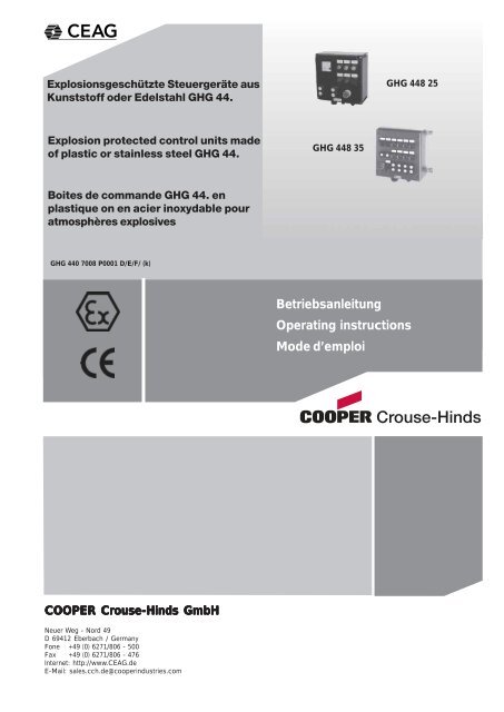
Explosionsgeschützte Steuergeräte aus Kunststoffoder Edelstahl GHG 44.Die Steuerschalter Ex 29 sind optional mit einermontierten Abschließvorrichtung versehen undebenso mit einem Vorhängeschloss abschließbar.6.2 Öffnen des Gerätes/Elektrischer AnschlussBild 112Anschlussbilder SchaltungSteuerschalter Ex 23/Ex 28/Ex 2960116019Angaben aus Punkt 3 und 4 sind bei derVerwendung zu berücksichtigen.Andere als die beschriebenen Anwendungensind ohne schriftliche Erklärung derFa. CEAG / Cooper Crouse-Hinds nichtzulässig.Beim Betrieb sind die in der <strong>Betriebsanleitung</strong>unter Punkt 7 genannten Anweisungenzu beachten.6 InstallationFür das Errichten / Betreiben sind die relevantennationalen Vorschriften (z.B. Betr.Si.V,Gerätesicherheitsgesetz in Deutschland) sowiedie allgemein anerkannten Regeln der Technikmaßgebend.Der elektrische Anschluss des Betriebsmittelsdarf nur durch Fachpersonal erfolgen.Das Schaltbild der Einbaukomponenten ist aufden Komponenten angegeben, dem Schaltgerätbeigelegt oder aus der <strong>Betriebsanleitung</strong>zu entnehmen.Bei verdrahteten Steuergeräten ist der demGerät beigelegte Anschlussplan zu beachten.! Die maximale Anzahl der verwendetenLeiter und internen Verbindungsleiterkann aus den Verdrahtungstabellen abSeite 24 entnommen werden.Nach dem Ausklappen des Klappgerüsteszur leichteren Einführung der Kabel undLeitungen bzw. zum Verdrahten auf die unterdem Klappgerüst eingebauten Anreihklemmenmuss das Klappgerüst wieder ordnungsgemäßbefestigt werden.Schaltwerk60606062606560336170. 021. 023. 024. 061. 063. 066. 0676.1 Montage / DemontageDie Montage der Kunststoff- oder Edelstahlsteuergerätekann ohne Öffnen der Gehäuseerfolgen.Die Steuergeräte dürfen bei der Direktmontagean der Wand nur an den vorgesehenenBefestigungspunkten eben aufliegen. Diegewählte Schraube muss der Befestigungsöffnungangepasst sein (siehe Maßbilder Seite3 + 4 sowie Bild 2 + 3, Seite 8).Sie dürfen die Öffnung nicht beschädigen (z.B.Verwendung einer Unterlegscheibe).Bei übermäßigem Anziehen können dieKunststoffsteuergeräte beschädigt werden.Die Kunststoffsteuergeräte GHG 444 2,GHG 448 2, GHG 449 2 und GHG 447 2 sindzur Befestigung auf den CEAG - Gerätehalternmittels Form- oder selbstschneidendenSchrauben geeignet (siehe Bild 4 - 8, Seite 9).Die betreffende Montageanleitung ist zubeachten.Die Montage der Wandbefestigungslaschenan den Edelstahlsteuergeräten GHG 444 3,GHG 448 3, GHG 449 3 und GHG 447 3erfolgt, wie in Bild 2 + 3 Seite 8 dargestelt.Auf die Mindestanzahl der Laschen achten!Werden die Einbaukomponenten (MessinstrumentAM 72 und AM 45, Drucktastersockel,Signalleuchtensockel, Steuerschaltersockel,Potentiometersockel usw.) zur leichterenVerdrahtung aus der Hutprofilschiene des inden Steuergeräten montierten Klappgerüstesausgeschnappt, sind die Komponentenhiernach wieder vorschriftsmäßig in dieentsprechende Einrastposition auf derHutprofilschiene des Klappgerüstes einzusetzen.Zum Ausschnappen der Komponenten (u.a.auch die Messinstrumente AM72 + AM45),werden die Rasthaken zum entriegeln nachaußen gezogen.Achtung: Die Einrastpositionen der Einbaukomponentenmüssen mit den Einkerbungender Hutprofilschiene übereinstimmen !Zur Aufrechterhaltung der Zündschutzart istder Leiteranschluss mit besonderer Sorgfaltdurchzuführen.Die Isolation muss bis an die Klemmeheranreichen. Der Leiter selbst darf nichtbeschädigt sein.Die minimal und maximal anschließbarenLeiterquerschnitte sind zu beachten (siehetechnische Daten).Alle Schrauben und / oder Muttern derAnschlussklemmen, auch die der nichtbenutzten, sind fest anzuziehen.Die optional eingebauten Standardklemmensind zum Direktanschluss von Leitern mitKupferadern ausgelegt.4 5 6SonderschaltwerkEin Schalten an der Achse der SteuerschaltersockelEx 23 und Ex 29 beigeöffnetem Gehäuse ist nicht zulässig(um die Schalter wieder korrekt schließenzu können).7 8 9Cooper Crouse-Hinds GmbH 7
Explosionsgeschützte Steuergeräte aus Kunststoffoder Edelstahl GHG 44.Anschlußbilder SchaltungSteuerschalter Ex 23/Ex 28/Ex 29SchaltwerkBild 2Schraube M6 x 16FederringBild 34 5 67 8 9Sonderschaltwerk. 049. 037. 191WandbefestigungslascheWandbefestigungslascheMontage der WandbefestigungslascheMontage rechtsMontage untenBei Messinstrumenten für Wandleranschlussn/1A (Bild1 , Pos 2, Seite 6) können über eineoben am Messinstrument angebrachteKlappe die Wechselskalen (Bild 1, Pos 1,Seite 6) ausgetauscht werden.Die Errichtungshinweise für eigensichereelektrische Betriebsmittel sind zu beachten.Es ist sicherzustellen, daß die für denspeziellen, eigensicheren Stromkreiszulässige äussere Kapazität und Induktivitätnicht überschritten wird.Wird das Betriebsmittel in der Ausführung"Schutzisoliert" ausgeführt, kann dasentsprechendeKlebeschild ( ) GHG 905 1002 P0005beim Hersteller angefordert werden.Wird die eingebaute Klemmentragschienenicht komplett mit Reihenklemmen bestückt,muss die Klemmentragschiene in denPotentialausgleich mit einbezogen werden.6.3 Kabel-und Leitungseinführungen(KLE);VerschlussstopfenEs dürfen generell nur bescheinigte KLE´sund Verschlussstopfen verwendet werden.Für bewegliche Leitungen sind Trompetenverschraubungenoder andere geeigneteEinführungen mit zusätzlicher Zugentlastungzu verwenden.Beim Einsatz von KLE mit einer niedrigeren alsder für das Gerät zutreffenden IP-Schutzart(siehe Seite 3) wird die IP-Schutzart desgesamten Gerätes reduziert.Die für die eingesetzten KLE maßgebendenMontagerichtlinien sind zu beachten.Nicht benutzte Einführungsöffnungen sind miteinem bescheinigten Verschlussstopfen zuverschließen, um die Mindestschutzartherzustellen.Es ist darauf zu achten, daß bei der Installationder KLE´s die für den Leitungsdurchmessergeeigneten Dichtungseinsätze verwendetwerden. Bei ausschneidbaren Dichtungseinsätzenist sicherzustellen,daß der Einsatzordnungsgemäß dem Leitungsdurchmesserangepasst wird.Zur Sicherstellung der erforderlichen Mindestschutzartsind die KLE´s fest anzuziehen.Bei übermäßigem Anziehen kann dieSchutzart beeinträchtigt werden.Achtung: Beim Anziehen der Hutmutter derMetall - KLE (Typ ADE) ist die Verschraubungmit einem geeigneten Werkzeuggegen Verdrehen zu sichern.Alle nicht benutzten metrischen CEAG /Cooper Crouse-Hinds KLE sind mit dembescheinigten Verschluss für metrische KLEzu verschließen.6.4 Kunststoff*-, Metallflanscheund MetallplattenMüssen Flanschplatten demontiert werden(z.B. zum Bohren von Einführungsöffnungen),ist bei der Montage zur Aufrechterhaltung derMindestschutzart auf den korrekten Sitz derFlanschplatte und den Sitz des Befestigungsbügelszu achten.Die Flanschplatten der Edelstahlklemmenkästensind so zu montieren, daß die IP-Schutzart gewährleistetbleibt. Dabei ist auf den exakten Sitz desDichtungselementes zu achten.Von aussen herangeführte PE-Leitungensind auf die dafür vorgesehene PE-Klemmeam Flansch anzuschließen. Der maximaleAnschlussquerschnitt beträgt 50 mm²Achtung: Metallflansche, Metallplatten undMetallverschraubungen müssen in denPotentialausgleich miteinbezogen werden.* z.Zt. nicht bescheinigt für Kategorie II D6.5 Schließen des Gerätes /DeckelverschlussBeim Aufsetzen der Gehäusedeckel istdarauf zu achten, daß die Vorsätze korrektmit den Einbaukomponenten übereinstimmenund der zum Gehäuseunterteilgehörige Deckel verwendet wird.Die Schaltgriffe der Steuerschalter Ex 23 undEx 29 müssen in der Stellung stehen, die siebeim Öffnen des Steuergerätes innehatten.Beim Aufsetzen des Deckels ist darauf zu achten,daß die Achse der Steuerschalter Ex 23 undEx 29 in die Mitnehmeröffnung des Schaltgriffeseingreift.Alle Fremdkörper sind aus dem Gerät zu entfernen.Zur Sicherstellung der erforderlichen Mindestschutzartsind die Deckelschrauben fest anzuziehen.Bei übermäßigem Anziehen kann dieSchutzart beeinträchtigt werden.6.6 InbetriebnahmeVor Inbetriebnahme des Betriebsmittels sind die inden einzelnen nationalen Bestimmungen genanntenPrüfungen durchzuführen. Ausserdem ist vorder Inbetriebnahme die korrekte Funktion und Installationdes Betriebsmittels und der Einbaukomponenten(Messinstrument, Signalleuchte, Tasterusw.) in Übereinstimmung mit dieser <strong>Betriebsanleitung</strong>und anderen anwendbaren Bestimmungenzu überprüfen.Die Nullpunkteinstellung des Messinstrumentezeigersist vor der Inbetriebnahme zu überprüfen.Gegebenenfalls mit der Justierschraube denMessgerätezeiger auf den Nullpunkt einjustieren.Unsachgemäße Installation und Betrieb derSteuergeräte kann zum Verlust der Garantieführen.8Cooper Crouse-Hinds GmbH
Explosionsgeschützte Steuergeräte aus Kunststoffoder Edelstahl GHG 44.Bild 4Gerätehalter Größe 3 fürRohrbefestigung,horizontalBild 8 2 x Gerätehalter Größe 3 für Rohrbefestigung, horizontalABefestigungslöcher für KunststoffSteuergerät GHG 444 2Bild 5Gerätehalter Größe 3 für Gitterrinnen- undWandbefestigung, horizontalAA = Befestigungslöcher für:Kunststoffsteuergerät GHG 448 27 (Maß X = 0 mm)Kunststoffsteuergerät GHG 449 27 nur vertikal (Maß X = 267mm)Kunststoffsteuergerät GHG 447 27 nur vertikal (Maß X = 540mm)EBefestigungslöcher für KunststoffSteuergerät GHG 444 25Bild 6 Gerätehalter Größe 3 für Rohrbefestigung,vertikalBefestigungslöcherfürKunststoffSteuergerätGHG 444 2Bild 7 Gerätehalter Größe 3 für Gitterrinnen-undWandbefestigung,vertikalCBBefestigungslöcherfürKunststoffSteuergerätGHG 444 27 Instandhaltung / WartungDie für die Wartung / Instandhaltung vonelektrischen Betriebsmitteln in explosionsgefährdetenBereichen geltenden nationalenBestimmungen sind einzuhalten(z.B. EN 60079-17).Vor Öffnen des Gehäuses Spannungsfreiheitsicherstellen bzw. geeigneteSchutzmaßnahmen ergreifen.Bei eigensicheren Stromkreisen ist dasArbeiten unter Spannung zulässig.Die erforderlichen Wartungsintervalle sindanwendungsspezifisch und daher in Abhängigkeitvon den Einsatzbedingungen vomBetreiber festzulegen.Im Rahmen der Wartung sind vor allem dieTeile, von denen die Zündschutzart abhängt,zu prüfen (z.B. Unversehrtheit der druckfestenKomponenten, des Gehäuses, der Dichtungenund der Kabel- und Leitungseinführungen),sowie die Schaltwerksfunktion.Sollte bei einer Wartung festgestellt werden,daß Instandsetzungsarbeiten erforderlich sind,ist Abschnitt 8 dieser <strong>Betriebsanleitung</strong> zubeachten.8 Reparatur / Instandsetzung /ÄnderungInstandsetzungsarbeiten / Reparaturen dürfennur mit CEAG / Cooper Crouse-HindsOriginalersatzteilen vorgenommen werden.Bei Schäden an der druckfesten Kapselung istnur ein Austausch zulässig. Im Zweifelsfalle istdas betroffene Betriebsmittel an CEAG /Cooper Crouse-Hinds zur Reparaturzurückzugeben.Reparaturen, die den Explosionsschutzbetreffen, dürfen nur von CEAG / CooperCrouse-Hinds oder einer qualifiziertenElektrofachkraft in Übereinstimmung mitnational geltenden Regeln durchgeführtwerden (z.B. EN 60079-19).Umbauten oder Änderungen am Betriebsmittelsind nicht gestattet; ausgenommen ist dasAnbringen von zusätzlichen KLE´s und dasMontieren von Anschlussklemmen im Rahmender Zulassung des Betriebsmittels oder nachAngaben des Herstellers.Bei Austausch einzelner Einbaukomponenten(Messinstrument, Taster usw.) ist Pkt. 6.2"Öffnen des Gerätes /Elektrischer Anschluss"zu beachten.9 Entsorgung /WiederverwertungBei der Entsorgung des Betriebsmittels undder Einbaukomponenten (Meßinstrument,Signalleuchte, Taster usw.) sind die jeweilsgeltenden nationalen Abfallbeseitigungsvorschriftenzu beachten.Zur Erleichterung der Wiederverwertbarkeitvon Einzelteilen sind Kunststoffteile mit demKennzeichen des verwendeten Kunststoffesversehen.Programmänderungen und -ergänzungen sindvorbehalten.Cooper Crouse-Hinds GmbH 9
Explosion protected control units made of plastic orstainless steel type GHG 44.Dimensions control units, plastic1 Technical data1.1 Control unit assemblies, plasticGHG 444 2GHG 448 2Marking acc. to 94/9/EC: II 2 G Ex d e ia/ib m [ia/ib] II C T4-T6II 2 D Ex tD A21 IP66/IP65 T80°C, T95°CEC type examination certificate: PTB 99 ATEX 1044Rated voltage:up to 690 VRated current:max. 40 APermissible ambient temperature:-20° C to +40° C (catalogue version)Deviating temperatures possible with special versions.Perm.storage temperature in original packing: -50° C to +80° CProtection category acc. to EN/IEC 60529: IP 66 (catalogue version)IP 65 with double push buttonInsulation class acc. to EN/IEC 61140: I - plastic terminal boxes fulfil this requirementII - with metal flangePE- terminal:2 x 4 mm²Terminals:acc. to customer´s specification and as certifiedCable entries:acc. to customer´s specification and as certifiedWeight when empty:(catalogue version)GHG 444 25 control unitapprox 1.5 kgGHG 448 25 control unitapprox 2.5 kgGHG 449 25 control unitapprox 4.5 kgGHG 447 25 control unitapprox 5.5 kgTest torques:Cover screws/ Terminal cross-section 2.50 NmCap nut of the plastic cable entry M12 1.65 NmCap nut of the plastic cable entry M16 - M20 2.50 NmCap nut of the plastic cable entry M253.50 NmCap nut of the plastic cable entry M32 - M 63 5.00 Nm1.2 Control unit assemblies, stainless steelGHG 449 2GHG 447 2Marking acc. to 94/9/EC: II 2 G Ex d e ia/ib m [ia/ib] II C T4-T6II 2 D Ex tD A21 IP66/IP65 T80°C, T95°CEC type examination certificate: PTB 99 ATEX 1044Rated voltage:up to 690 VRated current:max. 40 APermissible ambient temperature:-20° C to +40° C (catalogue version)Deviating temperatures possible with special versions.Perm.storage temperature in original packing: -50° C to +80° CProtection category acc. to EN/IEC60529: IP 66 (catalogue version)IP 65 with double push buttonInsulation class acc. to EN/IEC 61140: II - metal terminal boxes fulfil this requirementPE- terminal:2 x 4 mm²Terminals:acc. to customer´s specification and as certifiedCable entries:acc. to customer´s specification and as certifiedWeight when empty:(catalogue version)GHG 444 35 control unitapprox. 3.5 kgGHG 448 35 control unitapprox. 7.5 kgGHG 449 35 control unitapprox. 11.5 kgGHG 447 35 control unitapprox. 16.5 kgTest torques:Cover screws/ Terminal cross-section 2.5 NmCap nut of the Ex-e metal cable entry M16 7.5 Nm type, E1WF/e (Ex-e)Cap nut of the Ex-e metal cable entry M20 10.0 Nm type, E1WF/e (Ex-e)Cap nut of the Ex-e metal cable entry M25 15.0 Nm type, E1WF/e (Ex-e)Cap nut of the Ex-e metal cable entry M32 25.0 Nm type, E1WF/e (Ex-e)Cap nut of the Ex-e metal cable entry M40 30.0 Nm type, E1WF/e (Ex-e)Cap nut of the Ex-e metal cable entry M50 45.0 Nm type, E1WF/e (Ex-e)X = Fixing dimensions10Cooper Crouse-Hinds GmbH
Explosion protected control units made of plastic orstainless steel type GHG 44.Front actuator elements, dimensions in mmX = fixing dimensionsPush button Double push button1.7 AM45 / AM72 measuring instrument:EC type examination certificate:PTB 99 ATEX 2032 UMovement: Moving iron Ex e Moving coil Ex ib II CMeasuring accuracy: Class 2.5 Class 1.5Overload range: 10-fold at 25 sec. 10-fold at 5 sec.25-fold at 4 sec.50-fold at 1 sec.telltale 1:1.5Measuring range: n / 1 A 0 - 20 mA0 - 25 A direct 4 - 20 mAL i : - max. 0.1 mHC i : - max. 0.1 nFU i : - max. 30 VI i : - max. 150 mASupply terminals:2 x 1.5 - 4 mm²AM 45 weight:approx. 0.35 kgAM 72 weight:approx. 0.40 kgEMERGENCY-STOP Mushroom headmushroom head push buttonpush buttonEMERGENCY-STOPmushroom head pushbutton with keyKey-operatedpush buttonSignal lamp Control switch1.8 Ex 23 control switchEC type examination certificate:PTB 98 ATEX 1116 URated voltage:up to max.500 VRated current:10ASwitching capacity acc. to AC 15: 230V / 6 A 400V / 4,0 ASwitching capacity acc. to DC 13: 24V / 2 A 230V / 0,5 APerm. short-circuit back-up fuse:16 A/gL at 500 VDesign with gold-tipped contacts:max. 400 mASupply terminals:2 x 0.5 - 2.5mm²Weight: 1 level 2 levelsapprox. 0.20 kgapprox. 0.35 kg1.8.1 Ex 28 control switchEC type examination certificate:PTB 98 ATEX 1117 URated voltage:up to max.690 VRated current:16 A (up > 12 A wiring >=2,5 mm²)Switching capacity acc. to AC 15: 230V / 8 A 400V / 6,0 ASwitching capacity acc. to DC 13: 24V / 6 A 230V / 0,4 APerm. short-circuit back-up fuse:20 A/gL at 500 VDesign with gold-tipped contacts:max. 400 mASupply terminals:2 x 0,5 - 2,5mm² 1 x 1,0 - 6,0 mm²Weight: 1 level 2 levels 3 levelsca. 0.25 kg ca. 0.40 kg ca. 0.55 kgEx 23 control switchEx 29 control switch1.9 Ex 29 control switchEC type examination certificate:PTB 98 ATEX 1118 URated voltage:up to max.500 VRated current:16 Awith rated current >12 Athe cross section is > 2,5 mm²Switching capacity acc. to AC 15: 230V / 6 A 400V / 4,0 ASwitching capacity acc. to DC 13: 24V / 2 A 230V / 0,5 APerm. short-circuit back-up fuse:20 A/gL at 500 VDesign with gold-tipped contacts:max. 400 mASupply terminals:2 x 0.5 - 2.5 mm² or 1 x 1.0 - 6.0 mm²Weight: 1 level 2 level 3 levelapprox. 0.20kg approx. 0.40kg approx. 0.55kgMeasuring instrumentAM 45 AM 72* not yet certified for category II D12Cooper Crouse-Hinds GmbH
Explosion protected control units made of plastic orstainless steel type GHG 44.Fig. 112Contact arrangement CircuitryEx 23/ Ex 28/ EX 29 control switchCode60112 Safety <strong>instructions</strong>The plastic or stainless steelcontrol units GHG 44. are notsuitable for zone 0 and zone 20hazardous areas.The temperature class and explosiongroup marked on the control units shallbe observed.Modifications to the control units orchanges of their design are not permitted.They shall be used for their intendedpurpose and in perfect and cleancondition.For replacement and repair only genuineCEAG / Cooper Crouse-Hinds spare partsshall be used.4 Field of applicationThe plastic or stainless steel control unitsGHG 44. are suitable for use in zone 1, 2 and21, 22 hazardous areas acc. toIEC 60079-10-1 and -2.The enclosure materials employed, includingthe exterior metal parts, are made of highqualitymaterials which ensure a corrosionprotection and resistance to chemicalsubstances corresponding to the requirementsin a “normal industrial atmosphere”:- glass-fibre reinforced polyester- impact resistant polyamide- special steel AISI 316 LIn case of use in an extremely aggresiveatmosphere, please refer to manufacturer601960606062606560336170. 021. 023. 024. 061Repairs that affect the explosionprotection, may only be carried out byCEAG / Cooper Crouse-Hinds or aqualified electrician in compliance withthe respective national regulations.Prior to their taking into operation, thecontrol units will have to be checked inaccordance with the <strong>instructions</strong> as persection 6.The requirements of the EN 61241-0 and -1regarding excessive dust deposits andtemperature to be considered from theuser.Observe the national safety rules andregulations for prevention ofaccidents as well as the safety <strong>instructions</strong>included in these operating <strong>instructions</strong> setin italics the same as this text!3 Conformity with standardsThe control units have been designed,manufactured and tested by Cooper Crouse-Hinds (CCH), according to the state of the artand to DIN EN ISO 9001.The apparat is conform to the standardsspecified in the EC-Declaration of conformity.5 Application / PropertiesThe plastic or stainless steel control unitsGHG 44. are designed for the control in situ ofelectrical installations in explosiveatmospheres. The devices are individuallyfitted with built-in components that meet theirspecific application.The control units can, at option, be deliveredfitted with series terminals up to 2,5mm²under the hinged framework and wired readyfor connection by the customer.Adequately marked special versions of thecontrol units can be operated in „intrinsicallysafe circuits“. The electric limiting valuesapplicable to „intrinsic safety“ shall beobserved.The respective details on the equipment withelectrical contacts are given on thecomponent bases.The version fitted with gold-tipped contacts ismarked with a „G“ (for max. current load seeTechnical data).Switch mechanism. 063. 066. 06794/9 EC: Equipment and protective systemsintended for use in potentially explosiveatmospheres.The control units fulfil further requirementssuch as those of the ECdirective onelectromagnetic compatibility (2004/108/EEC).In order to achieve a reliable isolation, thenormally closed contacts are designed asforced break contacts. Where required, thebases are fitted with 0.6 W resistors, fine-wirefuses and diodes (max. dissipated energy 1 W).The measuring instrument serves for theindication in situ of electrical values. For thetype of measuring mechanism, accuracy andconnected version, see „Technical data“).4 5 6Special switchmechanism7 8 9When the switching collar on small controlswitches is cut out at the respective lockingposition, they can be padlocked (lockingshackle Ø up to 5 mm).Ex 23 control switch actuator elements shallbe provided with a drilled hole of 5.5 mm Ø atthe respective locking position on theirswitching collar and can thus be padlockedas described before.Cooper Crouse-Hinds GmbH 13
Explosion protected control units made of plastic orstainless steel type GHG 44.R1R2R3R4R5R1R2Actuator 1 x 4 poleS 4 S 2S 3 S 1S1 S2 S3 S4S 4S 3S112 22 34 4411 21 33 4314 24 34 4413 23 33 4312 22 32 4211 21 31 4112 24 34 4411 23 33 4312 22 32 4411 21 31 43Actuator 2 x 2 poleS 2S 1S2 S3 S412 22 34 4411 2133 4314 2434 4413 2333 43At option, the Ex 29 control switches areprovided with a fitted locking device so thatthey can also be padlocked.The 4 pole pushbutton contact can be addedwith the standard CCH actuators. If the 4pole pushbutton contact is added with anEmergency STOP Mushroom-headpushbutton actuator, then you have to usethe actuators with CCH order numberGHG 410 143737R.....This actuators can be recognize by the redthrust washer and black inserting sign.The data as per point 3 and 4 will have tobe taken into account with the use.Applications other than described are notpermitted without CEAG / Cooper Crouse-Hinds’s prior written consent.For the operation, the <strong>instructions</strong> statedin section 7 of the operating <strong>instructions</strong>will have to be observed.6 InstallationFor the mounting and operation, therespective national regulations (e. g. Betr.Si.V,equipment safety act) as well as the generalrules of engineering will have to be observed.6.1 MountingThe plastic and stainless steel control unitscan be mounted without opening theirenclosure.When being mounted directly onto the wall,the control units shall rest evenly only at thefastening points provided for them. Thechosen screw shall match the fastening hole(see dimensional drawing, page 10 + 11 andFig. 2, page 15).6.2 Opening the device/Electrical connectionThe electrical connection of the apparatus mayonly be carried out by skilled staff. The circuitdiagram of the built-in components is eithershown on these components or attached tothem or shown in the operating <strong>instructions</strong>. Asto wired control units, the circuit diagramattached to the device is to be observed.After the hinged framework has been foldedout in order to facilitate the introduction ofcables or the connection to the terminalsarranged under the hinged framework, it shallagain be fitted properly in place.If, for the sake of an easier wiring, the built-incomponents (AM 72 and AM 45 measuringinstrument, push-button base, signal lampbase, control switch base, potentiometer baseetc.) are snapped off the top hat rail fitted inthe hinged framework, the components will,thereafter, have to be properly re-inserted inthe lock-in position on the top hat rail of thehinged framework.! The total number of used conductors andinternal wiring conductors, can be found outin the wiring table page 24.In order to snap off the components(including measuring instruments AM 72 andAM 45), the snap-in hooks are unlocked bypulling them outwards.Mind: The lock-in positions of the built-incomponents shall match the notches onthe top hat rail!In order to maintain the explosion category,the conductors will have to be connected withspecial care.The insulation shall reach up to the terminal.The conductor itself must not be damaged.R3R4R5121112111211thrust washerredbaseyellow22212423222132313433314241444332 44Mushroom-head pushbutton actuator"EMERGENCY STOP"GHG 410 1437R....43inserting signblackThey shall not damage the hole (e.g. use of awasher).If the screws are overtightened, the plasticcontrol units may be damaged.The plastic control units GHG 444 2, 448 2,449 2 and GHG 447 2. are suitable forfastening onto CEAG / Cooper Crouse-Hindsapparatus holders by means of self-cuttingscrews (see fig. 4-8, page 16).The respective mounting <strong>instructions</strong> will haveto be observed.Mounting the wall mounting brackets onto thestainless steel control units GHG 444 3, 448 3,449 3 and GHG 447 3 is done as per fig. 2 + 3in page 15.Observe the min. No. of wall mountingbrackets!The connectible min. and max. conductorcross-sections will have to be observed (seetechnical data).All screws and/or nuts of the supply terminals,also of those remaining vacant, shall betightened down.The fitted optional standard terminals aredesigned for direct connection of conductorswith copper cores.Switching on the axis of the Ex 23 andEx 29 control switch base whilst theenclosure is open, is not permitted (inorder to be able to properly close theswitch again).On measuring instruments for c.t. connection n/1A (fig. 1, item 2, page 13) the interchangeablescales can be changed via a flap arranged onthe upper part of the measuring instrument (fig. 1,item 1, page 13).14Cooper Crouse-Hinds GmbH
Explosion protected control units made of plastic orstainless steel type GHG 44.Contact arrangement CircuitryEx 23/Ex 28/EX 29 control switchCodeSwitch mechanismFig. 2Screw M6 x 16Lock washerFig. 34 5 67 8 9Wall mounting bracketWall mountingbracketMounting the wallmounting bracket. 049. 037. 191Special switchmechanismMounting at right sideMounting at bottomThe <strong>instructions</strong> for the installation of intrinsicallysafe electrical apparatus are to be observed.It has to be ensured that the externalcapacitance and inductance permitted for thespecific intrinsically safe circuit are not exceeded.In the case of building up the electricalequipment in the "protective insulation"version, appropriate sticker( ) GHG 905 1002 P0005 can berequested by the manufacturer.If the inserted terminal rail is not equippedcompletely with line-up terminals, the terminalrail must be included in the equipotentialearth connection also.6.3 Cable entries (KLE);blanking plugsGenerally, only certified cable entries andblanking plugs may be used. Flexiblecables shall be used with trumpet-shapedcable glands or other suitable entries withadditional pull-relief.When using cable entries with a lower IPprotection than that which applies to thedevice (see page 11), the IP protection of thewhole device will be reduced.The mounting directives applicable to thecable entries fitted shall be observed.In order to establish the minimum protectioncategory, unused holes shall be closed with acertified blanking plug.Care has to be taken that when fitting thecable entries, sealing inserts appropriate tothe cable diameter be used.In case of sealing inserts that are cut out, itwill have to be ensured that the insert isproperly adapted to the cable diameter.In order to ensure the required minimumprotection category, the cable entries will haveto be tightened down.Overtightening might impair the protectioncategory.Attention: When tightening the cap nut ofthe type ADE metal cable entry, thescrewing is to be protected againsttwisting by means of a suitable tool.All vacant metric CEAG / Cooper Crouse-Hinds cable entries shall be closed with thecertified blanking plug for metric cable entries.6.4 Flange and metal platesIf flange plates have to be removed in case ofplastic terminal boxes (e.g. for drilling entryholes), attention will have to be paid to theproper fit of the flange plate and of the clampclip when mounting them in order to maintainthe minimum protection category.Flange plates for stainless steel terminal boxesshall be fitted so that the IP protection inmaintained. Pay attention to the proper seat ofthe sealing element.PE conductors fed from outside are to beconnected to the PE terminal provided onthe flange. The maximum cross-section is50mm².Attention: Metal flanges, metal plates andmetal cable glands shall be included in theequipotential earth connection.6.5 Closing the device /Cover closureWhen placing the enclosure cover care hasto be taken that the front actuator elementsexactly correspond to the built-incomponents and that the cover pertainingto the bottom part of the enclosure is used.The switching handles of the Ex 23 and Ex 29control switches shall have the same positionas they had when the apparatus was opened.When putting on the cover care has to betaken that the axis of the Ex 23 and Ex 29control switches engages in the driving hole ofthe switching handle.Any foreign matter shall be removed from theapparatus.In order to ensure the required minimumprotection category, the cover screws are tobe tightened down.Overtightening might impair the protectioncategory.6.6 Taking into operationPrior to taking the apparatus into operation,the tests specified in the relevant nationalregulations will have to be carried out. Apartfrom that, the correct functioning andinstallation of the apparatus in accordancewith these operating <strong>instructions</strong> and otherapplicable regulations will have to bechecked.Prior to taking into operation, the zero pointadjustment of the measuring instrument indexhas to be checked. Where necessary, themeasuring instrument index is to be adjustedto the zero point by means of the adjustingscrew.Incorrect installation and use of the controlunits can invalidate the guarantee.Cooper Crouse-Hinds GmbH 15
Explosion protected control units made of plastic orstainless steel type GHG 44.Fig. 4Apparatus holder size 3 for pipe mounting,horizontallyFig. 8 2 x Apparatus holder size 3 for pipe mounting, horizontallyAFastening holes for control unitGHG 444 25Fig 5Apparatus holder size 3 for channel andwall mounting, horizontallyAA =Fastening holes for:control unit GHG 448 27 (Dimensions X = 0 mm)control unit GHG 449 27 only vertically (Dimensions X = 267mm)control unit GHG 447 27 only vertically (Dimensions X = 540mm)Fig. 6Fig. 7EFastening holes for control unitGHG 444 25Apparatusholder size 3for pipemounting,verticallyCFasteningholes forcontrol unitGHG 444 25Apparatusholder forchannel andwall mounting,verticallyBFasteningholes forcontrol unitGHG 444 257 Maintenance / ServicingThe relevant national regulations whichapply to the maintenance/repair ofelectrical apparatus in explosiveatmospheres, will have to be observed(EN 60079-17).Before opening the enclosure make surethat the terminal box is disconnected fromthe voltage, or take the appropriateprotective measures.In case of intrinsically safe circuits, working ispermitted while voltage applies.The required maintenance intervals depend onthe respective application and will thereforehave to be determined by the user dependenton the conditions of use.When servicing the apparatus, particularlythose parts that are decisive for the type ofprotection against explosion, will have to bechecked (e. g. intactness of flameproofenclosed components, enclosure, cableglands, efficacy of the cover gaskets) and thefunctioning of the switch mechanism.If during servicing repairs prove to benecessary, section 8 of these operating<strong>instructions</strong> will have to be observed.8 Repairs / Overhaul /ModificationRepairs may only be carried out with genuineCEAG / Cooper Crouse-Hinds spare parts.In case of a damaged flameproof enclosure,only its replacement is permitted. In case ofdoubt, the respective apparatus will have tobe returned for repair to CEAG / CooperCrouse-Hinds.Repairs that affect the explosionprotection, may only be carried out byCEAG / Cooper Crouse-Hinds or aqualified electrician in compliance withthe applicable national rules(EN 60079-19).Modifications to the apparatus or changes ofits design are not permitted, except for themounting of additional cable entries and theinstallation of supply terminals in accordancewith the approval of the apparatus or acc. to<strong>instructions</strong> of the manufacturer.When replacing individual components(measuring instrument, push-button etc.),para. 6.2 „Opening the device/Electricalconnection“ is to be observed.9 Disposal / RecyclingWhen the apparatus is disposed of, therespective national regulations on wastedisposal will have to be observed.In order to facilitate the recycling of individualcomponents, plastic parts have been providedwith the identification mark of the plasticmaterial used.Subject to modifications or supplement of theproduct range.16Cooper Crouse-Hinds GmbH
Boites de commande GHG 44. en plastique on en acierinoxydable pour atmosphères explosivesDimensions boites de commandeen plastiqueGHG 444 2GHG 448 21 Caractéristiques techniques1.1 Boites de commande en plastiqueMarquage selon 94/9/CE et directive: II 2 G Ex d e ia/ib m [ia/ib] II C T4-T6II 2 D Ex tD A21 IP66/IP65 T80°C, T95°CAttestation d’examen CE de type: PTB 99 ATEX 1044Tension nominale:jusqu’à 690VCourant nominal:40 A au maxiTempérature ambiante admissible:-20°C à +40°C (modèles de liste)D’autres températures possibles avec des modèles spéciaux.Temp. de stockage dans l’emballage original: -50°C à +80°CIndice de protection selon EN/CEI 60529: IP 66 (modèles de liste)IP 65 bouton-poussoir doubleClasse d’isolation selon EN/CEI 61140: I - est remplie par les boites de bornes d'éclairageII - avec plaque métaliqueBorne PE:2 x 4 mm²Bornes de connexion:selon spécification du client et certificatEntrées de câble:selon spécification du client et certificatPoids à vide:(modèles de liste)Boite de commande GHG 444 25env. 1,5 kgBoite de commande GHG 448 25env. 2,5 kgBoite de commande GHG 449 25env. 4,5 kgBoite de commande GHG 447 25env. 5,5 kgCouples de serrage testés:Vis du couvercle / Borne de raccordement 2,50 NmEcrou borgne bas de l’entrée plastique M12 1,65 NmEcrou borgne bas de l’entrée plastique M16-M20 2,50 NmEcrou borgne bas de l’entrée plastique M25 3,50 NmEcrou borgne bas de l’entrée plastique M32-M50 5,00 Nm1.2 Boites de commande en acier inoxydableGHG 449 2GHG 447 2Marquage selon 94/9/CE et directive: II 2 G Ex d e ia/ib m [ia/ib] II C T4-T6II 2 D Ex tD A21 IP66/IP65 T80°C, T95°CAttestation d’examen CE de type: PTB 99 ATEX 1044Tension nominale:jusqu’à 690VCourant nominal:40 A au maxiTempérature ambiante admissible:-20°C à +40°C (modèles de liste)D’autres températures possibles avec des modèles spéciaux.Temp. de stockage dans l’emballage original: -50°C à +80°CIndice de protection selon EN/CEI 60529: IP 66,(modèles de liste)IP 65,bouton-poussoir doubleClasse d’isolation selon EN/CEI 61140: II - est remplie par les boites de bornes d'éclairage métaliqueBorne PE:2 x 4 mm²Bornes:selon spécification du client et certificatEntrées de câble:selon spécification du client et certificatPoids à vide:(modèles de liste)Boite de commande GHG 444 35 env. 3,5 kgBoite de commande GHG 448 35 env. 7,5 kgBoite de commande GHG 449 35env. 11,5 kgBoite de commande GHG 447 35env. 16,5 kgCouples de serrage testés:Vis du couvercle / Borne de raccordement 2,5 NmEcrou borgne bas de l’entrée métallique M 16 7,5 Nm type, E1WF/e (Ex-e)Ecrou borgne bas de l’entrée métallique M 20 10,0 Nm type, E1WF/e (Ex-e)Ecrou borgne bas de l’entrée métallique M 25 15,0 Nm type, E1WF/e (Ex-e)Ecrou borgne bas de l’entrée métallique M 32 25,0 Nm type, E1WF/e (Ex-e)Ecrou borgne bas de l’entrée métallique M 40 30,0 Nm type, E1WF/e (Ex-e)Ecrou borgne bas de l’entrée métallique M 50 45,0 Nm type, E1WF/e (Ex-e)X = dimensions de fixationCooper Crouse-Hinds GmbH 17
Boites de commande GHG 44. en plastique on en acierinoxydable pour atmosphères explosivesDimensions boites de commande enacier inoxydableGHG 444 31.3 Bouton-poussoir 2 pole et interrupteurAttestation d’examen CE de type:PTB 97 ATEX 1081 UTension nominale:jusqu’à 500 VCourant nominal Borne de connexion Température ambiantemaxiadmissible maxi14 A 2,5 mm² 40 °C16 A 4,0 mm² rigide 40 °C12 A 2,5 mm² 50 °C15 A 4,0 mm² rigide 50 °CPuissance de coupure AC15: 250V / 6 A 500V / 4,0 APuissance de coupure DC 13: 24V / 6 A 60V / 0,8 A 110V / 0,5 AModèle à pointes de contact d’or:400 mA au maxiBorne de connexion:2 x 1,0 - 2,5mm²; 1 x 4,0 mm²Poids:env. 0,15 kgGHG 448 31.3.1 Bouton-poussoir 4 pole et interrupteurAttestation d’examen CE de type:PTB 97 ATEX 1081 UTension nominale:jusqu’à. 500 VCourant nominal Borne de connexion Température ambiantemaxiadmissible maxi14 A 2,5 mm² 40 °C16 A 4,0 mm² rigide 40 °C12 A 2,5 mm² 50 °C15 A 4,0 mm² rigide 50 °CSchaltvermögen AC 15: 250V / 6 A 500V / 4,0 ASchaltvermögen DC 13: 24V / 6 A 60V / 0,8 A 110V / 0,5 Amit Goldspitzkontakten:max. 400 mAAnschlussklemmen:2 x 1,0 - 2,5 mm²; 1 x 4,0 mm²Prüdrehmoment Anschlussklemmen2,5 NmGewicht:ca. 0,17 kgGHG 449 31.4 Lampe de signalisationAttestation d’examen CE de type:PTB 98 ATEX 1040 UTension nominale:Ex ed IIC (LED) 20 V - 250 V AC/DCEx ed IIC 12 V - 24 V AC/DCEx d ia IIC 18 V - 30 V DCCourant nominale:Ex ed IIC 20 V - 250 V AC/DC (LED) 4 - 15 mAEx ed IIC 12 V - 24 V AC/DC max. 24 mAEx d ia IIC 18 V - 30 V DC max. 25 mABorne de raccordement:2 x 1,0 - 2,5 mm²Poids:env. 0,15 kg1.5 PotentiomètreAttestation d’examen CE de type:PTB 97 ATEX 1081 UTension nominale:jusqu’à 250 VPuissance:1 WDomaine de rotation: 270°Echelle: 0 - 100%Borne de raccordement:2 x 1,0 - 2,5 mm²Poids:env. 0,15 kgGHG 447 3X = dimensions de fixation18Cooper Crouse-Hinds GmbH
Boites de commande GHG 44. en plastique on en acierinoxydable pour atmosphères explosivesFig. 112Schémas des connexions CouplageCommutateur decommande Ex 23 / Ex 28 / Ex 29Mécanisme decommutation6011601960606062606560336170. 021. 023. 024. 061. 063. 066. 0674 5 6Mécanisme decommutationspécial7 8 92 Consignes de sécuritéLes boites de commande enplastique on en acier inoxydableneconviennent pas à l’emploien zone 0 et zone 20.Le groupe d’explosion et la classe detempérature marqués sur les appareilsdevront être respectés.Il n’est pas permis de transformer ou demodifier les boites de commande.Seuls des boites de commande intactes etparfaites devront être employées pour lafonction qui leur est dévolue.Seules des pièces de rechangehomologuées d’origine CEAG / CooperCrouse-Hinds devront être utiliséescomme remplacement et pour desréparations.Des réparations qui portent sur laprotection contre l’explosion, ne devrontêtre exécutées que par CEAG / CooperCrouse-Hinds ou par un électricienqualifié en conformité avec larèglementation nationale en vigueur.Avant la mise en service, les boites decommande doivent être vérifiées selonl’instruction donnée dans la section 6.Les exigences des EN 61241-0 et -1 en cequi concerne des dépôts de poussièredémesurés et une température doiventêtre considérées par I’utilisateur.Respectez les prescriptions nationales desécurité et de prévoyance contre lesaccidents ainsi que les consignes desécurité qui suivent dans ce mode d’emploiet qui sont mises en italique comme ce texte!3 Conformité avec les normesLesboites de commande, fabriquées etcontrôlées par Cooper Crouse-Hinds(abrégé ci-dessous par CCH) conformémentà DIN EN ISO 9001.Les boîtes à bornes sont conformes auxnormes reprises dans la déclaration deconformité94/9 CE: Appareils et systèmes deprotection destinés à être utilisés enatmosphère explosible.De plus, les boites de commande répondent àd’autres exigences comme par exemple, cellesde la directive CE “Compatibilitéélectromagnétique” (2004/108/CEE).4 Domaine d’utilisationLes boites de commande conviennent àl’emploi en les zones 1, 2 et 11 (21, 22) d’uneatmosphère explosive selonCEI 60079-10-1 et -2!Pour l’enveloppe, y compris les piècesmétalliques extérieures, des matières dequalité supérieure ont été employées quiassurent une protection appropriée contre lacorrosion et une résistance contre des agentschimiques en “atmosphère industriellenormale”:- polyester chargé verre- polyamide anti-choc- acier spécial AISI 316 LEn cas d‘utilisation en atmosphèreextrèmement corrosive, vous pouvez obtenirdes informations complémentaires sur larésistance chimique des matériel utilisés chezla succursale Cooper Crouse-Hinds de votrerégion.5 Utilisation / PropriétésLes boites de commande en plastique on enacier inoxydable GHG 44. servent à lacommande sur place d’installationsélectriques en atmosphère explosive.Dépendant de l’emploi spécifique et suivantle cas, les appareils sont dotés descomposants encastrés appropriés.Au choix, les boites de commande peuventou être équipées des bornes jusqu’à 2,5mm² au-dessous du cadre d’encastrementou être complètement câblees pour leraccordement par le client.Des exécutions spéciales de la boite decommande avec repère appropriée peuventêtre exploitées dans des „circuits à sécuritéintrinsèque“.Les valeurs limites valables pour la „sécuritéintrinsèque“ doivent être respectées.L’équipement en contacts électriques setrouve sur les socles de composants. L’exécutionà pointes de contact d’or porte larepère "G" (intensité max. admissible selonles caractéristiques techniques).Afin d’obten une déconnexion fiable, descontacts de rupture forcée ont été montéscomme contacts normaux.Suivant le cas, les socles sont aussi dotés desrésistances de 0,6 W, des fusibles pour faibleintensité et des diodes (puissance dissipée de 1W au maxi).L’instrument de mesure AM 72 et AM 45 sert àl’indication sur place des grandeurs électriques.Le type du mécanisme de mesure, la justesse etle type de raccordement sont indiqués dans lescaractéristiques techniques.Si le collet de commutation des manipulateurs estdécoupé à la position de verrouillage respective,il est possible de les cadenasser dans cetteposition (Ø de l’étrier jusqu’à 5 mm).20Cooper Crouse-Hinds GmbH
Boites de commande GHG 44. en plastique on en acierinoxydable pour atmosphères explosivesSchémas des connexions CouplageCommutateur decommande Ex 23 / Ex 28 / Ex 29Mécanisme decommutationVis M6 x 16 Patte de fixationRondelle à éventail muraleFig. 3. 049. 037. 1914 5 6Mécanisme decommutationspécialMontage de patte de fixationmuraleMontage à droiteMontage faceinférieureEn cas d’instruments de mesure pourconnexion au transformateur d’intensité n/1A(fig. 1, pos. 2, page 17), un volet disposé surla partie supérieure de l’instrument demesure permet d’échanger les cadransinterchangeables (fig. 1, pos. 1, page 17)Les <strong>instructions</strong> pour le montage du matérielélectrique à sécurité intrinsèque doivent êtrerespectées.Il faut assurer que la capacitance etl’inductance extérieures admissibles pour lecircuit spécifique à sécurité intrinsèque nesoient pas dépassées.Si le moyen d’exploitation est réalisé dansl’exécution „double isolation“, l’autocollantcorrespondant ( ) GHG 905 1002 P0005peut être demandé au fabricant.Si le profilé support de bornes n’est pascomplètement équipés de barrettes dejonction, le profilé support de bornes doit êtreintégré dans l’équipotentialité.7 8 9 6.3 Entrées de câble (KLE) /Bouchons de fermetureGénéralement, seuls des bouchons defermeture et des entrées de câble certifiésdoivent être utilisés. Pour des câblesflexibles il faudra utiliser des presseétoupesen forme de trompette oud’autres entrées appropriées avecFig. 2 Patte de fixation muraledécharge de traction supplémentaire.Lorsque des entrées de câble avec un indicede protection IP inférieur à celui de la boîte àbornes sont employées (voir page 3), l’indicede protection IP de l’ensemble sera réduit.Les directives pour le montage quis’appliquent aux entrées de câble utilisées,doivent être respectées.Des ouvertures d’entrée non utilisées doiventêtre fermées avec un bouchon de fermeturecertifié pour établir l’indice de protectionminimum.Lors du montage des entrées de câble ilfaudra veiller à ce que des garnituresd’étanchéité correspondant au diamètre ducâble soient utilisées.En cas de garnitures qui doivent être coupéessur mesure, il faudra faire attention à ce que lagarniture soit adaptée au diamètre du câble.Les entrées de câble doivent être serrées àfond pour maintenir l’indice de protectionminimum.Au cas où elles seraient forcées, celapourrait être nuisible à l’indice deprotection.Attention: Lors de serrer l'écrou borgnede l'entrée de câble métallique du typeADE, il faut protéger le vissage d'êtretordu à l'aide d'un outil approprié.Toutes les entrées de câble métriques CEAG/ Cooper Crouse-Hinds non utilisées doiventêtre fermées avec un bouchon de fermeturecertifié pour des entrées de câble métriques.6.4 Plaques à bridesde plastique et métalliquesSi les plaques à brides doivent être démontées(pour percage d’entrées de câble, parexemple) il faudra veiller lors du montage aumaintien de l’indice de protection en replacantcorrectement la plaque ainsi que les brides deserrage.Les plaques à brides des boites en acierinoxydable sont montées de telle facon quel’indice de protection IP soit respecté. Il fautégalement veiller au bon logement du jointd’étanchéité.Des conducteurs PE amenés de l’extérieurdoivent être connectés à la borne PE prévueà cet effet sur la bride. La section maximaleest de 50 mm²Attention: les brides métalliques, lesplaques de fond métalliques et les presseétoupemétalliques doivent être reliés aumême potentiel.6.5 Fermeture e de l’appareil eil /Fermeture e à couverclecleLorsque le couvercle est posé surl’enveloppe, il faut veiller à ce que les têtesde commande soient en concordanceexacte avec les composants encastrés etque seul le couvercle appartenant à la partieinférieure de l’enveloppe soit utilisé.Le garrot du commutateur de commandeEx 23 et Ex 29 doit être dans la même positionqu’il avait lorsque l’appareil fut ouvert.Lorsque le couvercle est posé, il faut veiller àce que l’axe des commutateurs de commandeEx23 et Ex 29 s’engage dans le troud’entraînement du garrot du commutateur.Tout corps étranger doit être ôté de l’appareil.Les vis de couvercle doivent être serrées à fondafin de maintenir l’indice de protection minimum.Si les vis sont forcées, cela peut êtrenuisible à l’indice de protection.6.6 Mise en serviceAvant la mise en service de l’appareil, lesvérifications spécifiées dans les règlementsnationaux individuels devront être exécutées.De plus, il faudra vérifier son fonctionnement etinstallation corrects en conformité avec ce moded’emploi et avec d’autres règlements yapplicables.Avant la mise en service, le réglage de zero del’aiguille de l’instrument de mesure devra êtrevérifié. Si nécessaire, l’aiguille doit être réglé aupoint de zéro au moyen de la vis de réglage.L’installation ou l’utilisation incorrecte deces boites à bornes peut annuler la garantie.22Cooper Crouse-Hinds GmbH
Boites de commande GHG 44. en plastique on en acierinoxydable pour atmosphères explosivesFig. 5Porte-appareils taille 3 pour fixation auxFig 9Porte-appareils 2 x taille 3 pour fixation aux tubes, horizontalementCTrous de fixation pour boite decommande GHG 444 2Fig 6Porte-appareils taille 3 pour fixation au muret au conduit de grille, horizontalementAA= Trous de fixation pour:Boite de commande GHG 448 2 (Dim. X = 0 mm)Boite de commande GHG 449 2 seulement verticalement (Dim. X = 267 mm)Boite de commande GHG 447 2 seulement verticalement (Dim. X = 540 mm)8 Réparations / Remise en étatFig. 7ETrous de fixation pour boite decommande GHG 444 2Porte-appareils taille 3 pourfixation auxtubes,verticalementCTrous defixation pourboite decommandeGHG 444 27 Maintien/EntretienetienLa règlementation nationale en vigueurpour le maintien et l’entretien du matérielélectrique pour atmosphère explosive doitêtre respectée (EN 60079-17).Avant d’ouvrir l’enveloppe, débrancherl’appareil de la tension ou prendre desmesures préventives appropriées.En cas de circuits à sécurité intrinsèque, destravaux sont permis sous tension.Des réparations ne doivent être exécutéesqu’à l’aide des pièces de rechange d’origineCEAG / Cooper Crouse-Hinds.En cas de défauts sur l’enveloppe antidéflagrante,seul un remplacement est admissible.Dans le doute, l’appareil défectueux devraêtre renvoyé à CEAG / Cooper Crouse-Hindspour être réparé.Des réparations qui portent sur laprotection contre l’explosion, ne devrontêtre exécutées que par CEAG / CooperCrouse-Hinds ou par un électricienqualifié en conformité avec larèglementation nationale en vigueur(EN 60079-19).Il n’est pas permis de transformer ou demodifier ces appareils, sauf pour le montagedes entrées de câble supplémentaires enconformité avec leur homologation.Fig. 8Porte-appareils taille 3 pourfixation aumur etau conduit degrille,BTrous defixation pourboite decommandeGHG 444 2Les intervalles de service requis dépendent del’emploi spécifique et devront donc être fixéspar l’utilisateur en tenant compte desconditions d’utilisation.Lors de l’entretien des commutateurs, surtoutles composants qui sont essentiels à leurmode de protection contre l’explosion, doiventêtre vérifiés (par ex. intégrité des composantsantidéflagrants et du boitier, efficacité desjoints de couvercle et resserrement desentrées de câble) ainsi que le fonctionnementdu mécanisme de commutation.Si, lors d’un entretien, on constate que destravaux d’entretien sont nécessaires, il faudrasuivre le point 8 de ce mode d’emploi.En cas de remplacer des composants encastrésindividuels (instrument de mesure, boutonpoussoiretc.), l’alinéa 6.2 „Ouverture de l’appareil/Raccordement électrique“ devra être respecté.9 Évacuation des déchets/RecyclageLors de l’évacuation de ce matériel électrique,la règlementation nationale respective envigueur devra être respectée.Pour faciliter la réutilisation des composantsindividuels, des pièces en matière plastiqueont été repérées de la marque distinctive de lamatière plastique employée.Sous réserve de modification oud’informations supplémentaires.Cooper Crouse-Hinds GmbH 23
Verdrahtungstabelle wiring table table de câblageGHG 444 GHG 448I / A in mm²1,5 2,5 4 6 10 16 25 3536 62 1)10 62 6216 7 26 6220 10 34 4825 12 4635 10 4850 36 4663 7 30 3080 12 30 73100 14 19 3)125 2)160200I / A in mm²1,5 2,5 4 6 10 16 25 3536 76 1)10 76 7616 10 30 7620 10 36 5825 12 32 5835 8 58 4650 8 42 3263 6 32 3080 10 30100 3)125 2)160200GHG 449I / A in mm²1,5 2,5 4 6 10 16 25 3536 304 1)10 140 20416 14 36 18020 14 64 24025 28 108 24035 28 90 9650 10 34 7063 14 60 6480 18 20100 3)125 2)160GHG 447I / A in mm²1,5 2,5 4 6 10 16 25 3536 314 1)10 86 26016 10 72 20020 33 64 2025 30 70 20035 28 68 16050 10 50 11463 14 60 10680 18 18100 3)125 2)160200Beispiel für die Anzahl der verwendetenLeiterExample of the number of the usedconductorsExemple de nombre de conducteur1 Leiter von außen 1,5 mm²2 Interner Verbindungsleiter 1,5 mm²3 Interner Verbindungsleiter 1,5 mm²4 Interner Verbindungsleiter 1,5 mm²5 Leiter nach außen 1,5 mm²1 conductor coming in 1,5 mm²2 internal wire connections 1,5 mm²3 internal wire connections 1,5 mm²4 internal wire connections 1,5 mm²5 conductor coming out 1,5 mm²für die Berechnung müssen5 Leiterberücksichtigt werden34for calculation note5 conductors121 conducteur introduit 1,5 mm²2 conducteur de liaison interne 1,5 mm²3 conducteur de liaison interne 1,5 mm²4 conducteur de liaison interne 1,5 mm²5 conducteur sortir 1,5 mm²GHG4445pour le calcul,5 conducteursdoivent être pris en considération24Cooper Crouse-Hinds GmbH
Anmerkungen1) max. Klemmenzahl in Abhängigkeit vonobengenannter Gehäusetype und dereingebauten 2-Leiter-Klemme.2) max. Klemmenzahl in Abhängigkeit vonobengenannter Gehäusetype und dermax. Anzahl der Leiter.3) max. Anzahl der Leiter in Abhängigkeitvom Querschnitt und dem zulässigenDauerstrom für vorgenannte Gehäusetype.Als Leiter zählt jeder eingeführteLeiter und jeder interne Verbindungsleiter.Brücken und Schutzleiter werden nichtgezählt.Bei der Auswahl der zulässigen Dauerströmefür die Querschnitte sind diemax. Belastungsströme, der verwendetenKlemmen und der angeschlossenenKabel- und Leitungen zu beachten.Leitungen, im Inneren der nach obigerTabelle bestückten Gehäuse, müssen füreine Temperatur von 70 - 80 °C geeignetsein. Mischbestückungen von Stromkreisenunterschiedlicher Querschnitte undStröme sind durch anteilige Ausnutzungder Tabellenwerte möglich.Note:1) max. number of terminals depending onthe above mentioned apparatus typeand the built-in 2 wire terminals.2) max. number of terminals depending onthe above mentioned apparatus typeand the amx. number of conductors3) max. number of conductors dependingon the cross-section and allowedcontinuous current for the mentionedapparatus type. The number ofconductors is the sum of all incomingconductors and internal wireconnections.Bridge links and earth conductors do notcount.To determine the permissible continuouscurrent for the selected conductorcross-section, the max. rated current forthe terminal used and the connectedconductors must be observed.Conductors used within the enclosuremust be suitable for a temperature of 70– 80°C. Mixed circuits of different crosssectionsand currents are possible byusing the table values in the respectiveproportions.Remarques1) nombre max. de bornes en fonction dutype de boîtier mentionné ci-dessus etde la borne 2 fils intégrée.2) nombre max. de bornes en fonction dutype de boîtier mentionné ci-dessus etdu nombre max. de conducteurs.3) nombre max. de conducteurs enfonction de la section et du courantpermanent admissible pour le type deboîtier précité. Est compté commeconducteur tout conducteur introduit ettout conducteur de liaison interne.Les ponts et conducteurs de protectionne sont pas comptés.Lors de la sélection des courantspermanents admissibles pour lessections, on doit tenir compte descourants de charge max., des bornesutilisées et des câbles et lignesraccordés. Les lignes à l’intérieur desboîtiers équipés selon le tableau ci-dessusdoivent convenir pour une température de70 - 80 °C. Les équipements mixtes decircuits électriques de sections et courantsdifférents sont possibles moyennantl’application correspondante des valeursdu tableau.Beispiel zu Tabelle GHG 448:Example to GHG 448:Querschnitt / mm² Strom / A Anzahl AuslastungCross section / mm² Current / A Quantity Quantity UtilisationSection / mm² Courant / A Nombre Charge1,5 10 38 (von 76) = 50,0 %2,5 16 8 (von 30) = 26,6 %4,0 20 4 (von 36) = 11,1 %Summe = 87,7 %
26Cooper Crouse-Hinds GmbH
Cooper Crouse-Hinds GmbH 27
COOPER Crouse-Hinds GmbHNeuer Weg - Nord 49D 69412 Eberbach / GermanyFone +49 (0 )6271 / 806-500Fax +49 (0 )6271 / 806-476Internet: www.CEAG.deE-Mail: sales.cch.de@cooperindustries.comGHG 440 7008 P0001 D/E/F/ (k) Auflage/10.10/ZI