INSTALLATION INSTRUCTIONS for LIGHT BOX 20627R3 20628R3
INSTALLATION INSTRUCTIONS for LIGHT BOX 20627R3 20628R3
INSTALLATION INSTRUCTIONS for LIGHT BOX 20627R3 20628R3

You also want an ePaper? Increase the reach of your titles
YUMPU automatically turns print PDFs into web optimized ePapers that Google loves.
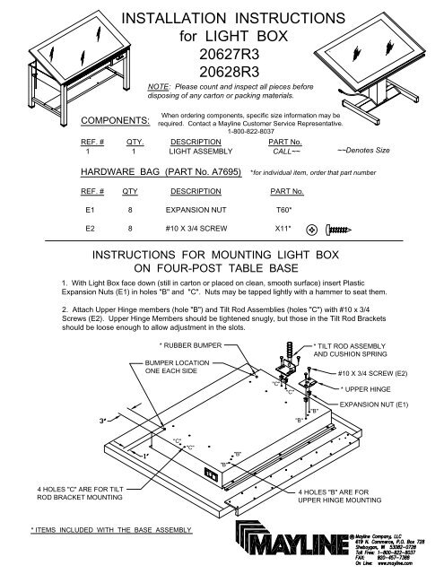
COMPONENTS:<strong>INSTALLATION</strong> <strong>INSTRUCTIONS</strong><strong>for</strong> <strong>LIGHT</strong> <strong>BOX</strong><strong>20627R3</strong><strong>20628R3</strong>NOTE: Please count and inspect all pieces be<strong>for</strong>edisposing of any carton or packing materials.When ordering components, specific size in<strong>for</strong>mation may berequired. Contact a Mayline Customer Service Representative.1-800-822-8037REF. # QTY. DESCRIPTION PART No.1 1 <strong>LIGHT</strong> ASSEMBLY CALL~~~~Denotes SizeHARDWARE BAG (PART No. A7695) *<strong>for</strong> individual item, order that part numberREF. # QTY DESCRIPTION PART No.E1 8 EXPANSION NUT T60*E2 8 #10 X 3/4 SCREW X11*<strong>INSTRUCTIONS</strong> FOR MOUNTING <strong>LIGHT</strong> <strong>BOX</strong>ON FOUR-POST TABLE BASE1. With Light Box face down (still in carton or placed on clean, smooth surface) insert PlasticExpansion Nuts (E1) in holes "B" and "C". Nuts may be tapped lightly with a hammer to seat them.2. Attach Upper Hinge members (hole "B") and Tilt Rod Assemblies (holes "C") with #10 x 3/4Screws (E2). Upper Hinge Members should be tightened snugly, but those in the Tilt Rod Bracketsshould be loose enough to allow adjustment in the slots.* RUBBER BUMPERBUMPER LOCATIONONE EACH SIDE"C""C"* TILT ROD ASSEMBLYAND CUSHION SPRING#10 X 3/4 SCREW (E2)* UPPER HINGE"B""B"EXPANSION NUT (E1)"C""C""B""B"4 HOLES "C" ARE FOR TILTROD BRACKET MOUNTING4 HOLES "B" ARE FORUPPER HINGE MOUNTING* ITEMS INCLUDED WITH THE BASE ASSEMBLY
3. Mount self-adhesive rubber bumpers* in locations shownat both rear corners of pan.4. Mount Light Top to table base by inserting upper hingemembers into mating hinge members on table rail with theLight Top in a near vertical position.* TILT ROD w/Cushion Spring* Tilt Rod Guide5. Slide a cushion spring on each tilt rod and insert the rods intothe tilt rod guides on the side rails of the table.6. Raise and lower the Light Top through its range of travel sothat the tilt rods brackets locate themselves. Then tighten the tiltrod bracket screws. Do not over tighten.
<strong>INSTRUCTIONS</strong> FOR MOUNTING <strong>LIGHT</strong> <strong>BOX</strong>ON POWER TABLE BASEEXPANSION NUT (E1)These 2 holes <strong>for</strong> mounting of Power Basecontrol switch box at final assembly.1. With Light Box face down (still in carton or placed on clean, smoothsurface) insert Plastic Expansion Nuts (E1) in holes "A". Nuts may be tappedlightly with a hammer to seat them.2. Place top mounting brackets on the power base in near horizontal position.3. Center Light Top over board brackets with pencil trough to front of base.Align holes in the light top with the slots in the brackets.4. Attach the light box with #10 x 3/4 Screws (E2).NOTE: Screws should only be drawn up snug. DO NOT over tighten.FOLLOW <strong>INSTRUCTIONS</strong> WITH BASE FOR CONTROL <strong>INSTALLATION</strong>
DIMMING CONTROLON - OFF SWITCHRemove these 3 screws<strong>for</strong> lamp accessADJUSTMENTS AND SERVICE FOR <strong>LIGHT</strong> TOP1. WARNING - Always disconnect power be<strong>for</strong>e opening to avoid shock hazard.For proper operation, unit must be plugged into a 3 wire grounded outlet.2. Lights are operated by depressing push-button once to turn light on or onceto turn off. Sliding the dimmer control lever controls the brightness level.3. To replace lamps:A. Remove three 1/4-28 Round head matching screws close to front.B. Lift wood top frame by edge and support with prop rod found in righthand side of lamp compartment. Lift rear end of rod out of clip andinsert rod end into round hole in underside of top frame.USE ONLY cool white rapid start lamps, either F25T8 (36" long) orF32T8 (48" long).DO NOT USE "Wattmizer" of other wattage lamps.4. For best operation, replace all bulbs at same time.5. In<strong>for</strong>mation on the electrical system shown <strong>for</strong> reference only<strong>for</strong> service by qualified electrician.