ASSEMBLY INSTRUCTIONS for MOUNTING STRAIGHTEDGE on POST FORMED TOPS
ASSEMBLY INSTRUCTIONS for MOUNTING STRAIGHTEDGE on ...
ASSEMBLY INSTRUCTIONS for MOUNTING STRAIGHTEDGE on ...
- No tags were found...

Create successful ePaper yourself
Turn your PDF publications into a flip-book with our unique Google optimized e-Paper software.
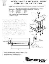
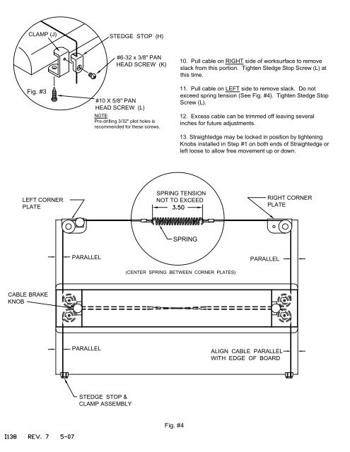
CLAMP (J)STEDGE STOP (H)Fig. #3#6-32 x 3/8" PANHEAD SCREW (K)#10 X 5/8" PANHEAD SCREW (L)NOTE:Pre-drilling 3/32" pilot holes isrecommended <str<strong>on</strong>g>for</str<strong>on</strong>g> these screws.10. Pull cable <strong>on</strong> RIGHT side of worksurface to removeslack from this porti<strong>on</strong>. Tighten Stedge Stop Screw (L) atthis time.11. Pull cable <strong>on</strong> LEFT side to remove slack. Do notexceed spring tensi<strong>on</strong> (See Fig. #4). Tighten Stedge StopScrew (L).12. Excess cable can be trimmed off leaving severalinches <str<strong>on</strong>g>for</str<strong>on</strong>g> future adjustments.13. Straightedge may be locked in positi<strong>on</strong> by tighteningKnobs installed in Step #1 <strong>on</strong> both ends of Straightedge orleft loose to allow free movement up or down.LEFT CORNERPLATESPRING TENSIONNOT TO EXCEEDRIGHT CORNERPLATESPRINGPARALLELPARALLEL(CENTER SPRING BETWEEN CORNER PLATES)CABLE BRAKEKNOBPARALLELALIGN CABLE PARALLELWITH EDGE OF BOARDSTEDGE STOP &CLAMP <str<strong>on</strong>g>ASSEMBLY</str<strong>on</strong>g>Fig. #4