ROBOT MOUNTED ROTARY ATOMIZER INDIRECT CHARGE
Serv. Man LN-9268-11.4 - Ransburg
Serv. Man LN-9268-11.4 - Ransburg

You also want an ePaper? Increase the reach of your titles
YUMPU automatically turns print PDFs into web optimized ePapers that Google loves.
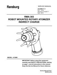
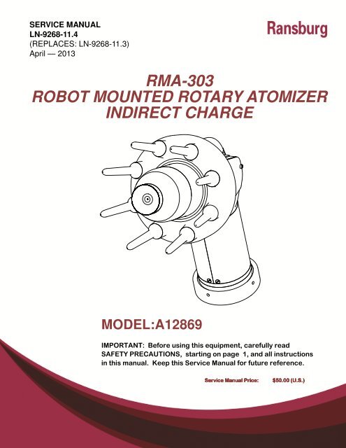
SERVICE MANUALLN-9268-11.4(REPLACES: LN-9268-11.3)April — 2013RMA-303<strong>ROBOT</strong> <strong>MOUNTED</strong> <strong>ROTARY</strong> <strong>ATOMIZER</strong><strong>INDIRECT</strong> <strong>CHARGE</strong>MODEL:A12869IMPORTANT: Before using this equipment, carefully readSAFETY PRECAUTIONS, starting on page 1, and all instructionsin this manual. Keep this Service Manual for future reference.Service Manual Price:$50.00 (U.S.)
RMA-303 Indirect Charge - ContentsLN-9268-11.4
RMA-303 Indirect Charge - ContentsCONTENTSPAGESAFETY: 1-7SAFETY PRECAUTIONS ......................................................................................................... 1HAZARDS / SAFEGUARDS................................................................................................... 2-7INTRODUCTION: 8-27FEATURES ............................................................................................................................... 8GENERAL DESCRIPTION ................................................................................................... 9-10SPECIFICATIONS ............................................................................................................. 11-12IMPORTANT NUMBERS……………………………………………………………………………..13GRAPHICAL INFORMATION ............................................................................................. 15-24RMA-303 TOOL POINT, CENTER OF GRAVITY,ANDENVELOPE DIMENSIONS (Mono and Dual Flex) .................................................................. 25CIRCUIT DIAGRAM ............................. ……………………………………………………………..26VALVE SCHEMATIC ........... …………………………………………………………………………27INSTALLATION: 29-38AIR FILTER INSTALLATION................................................................................................... 29TUBE SIZE / AIR PRESSURE REQUIREMENTS ................................................................... 29EQUIPMENT GROUNDING AND SAFETY RECOMMENDATIONS ....................................... 30AIR HEATER REQUIREMENTS ............................................................................................. 31AIR FILTRATION REQUIREMENTS ....................................................................................... 33MOUNTING ............................................................................................................................ 34ELETRICAL AND FIBER OPTIC CONNECTIONS .................................................................. 34FLUID CONNECTIONS .......................................................................................................... 34TYPICAL INSTALLATION ....................................................................................................... 35TUBING BUNDLE INSTALLATION ......................................................................................... 36BUNDLE LUBRICATION ......................................................................................................... 36INTERLOCKS .................................................................................................................... 36-38OPERATION: 39-46FLUID FLOW RATE CONTROL .............................................................................................. 39FLUID VALVE CONTROL (Trigger, Dump, and Solvent) ........................................................ 40TURBINE SPEED ................................................................................................................... 41BEARING AIR ADJUSTMENT ................................................................................................ 41SHAPING AIR # 1 (SAI) (Pattern Control Air) .......................................................................... 41SHAPING AIR #2 (SAO) (Pattern Control Air) ......................................................................... 42BRAKE AIR ............................................................................................................................. 43ELECTROSTATIC VOLTAGE ................................................................................................. 43TARGET DISTANCE .............................................................................................................. 43GENERAL OPERATING SEQUENCE ............................................................................... 43-44PROTECTIVE COVERS .................................................................................................... 45-46(Continue On Next Page)LN-9268-11.4
RMA-303 Indirect Charge - ContentsCONTENTS (Cont.)PAGEMAINTENANCE: 47-82O-RINGS ................................................................................................................................ 47CLEANING PROCEDURES ................................................................................................... 47VIBRATION NOISE ................................................................................................................ 49TURBINE MAINTENANCE ..................................................................................................... 49AIR FILTERS / ELEMENT REPLACEMENT ........................................................................... 49GENERAL MAINTENANCE .................................................................................................... 50PREVENTIVE MAINTENANCE ......................................................................................... 50-51BELL CUP PREVENTIVE MAINTENANCE ............................................................................ 52BELL CUP CLEANING ........................................................................................................... 53CLEANING SHAPING AIR HOLES ......................................................................................... 54RMA-303 PREVENTIVE MAINTENANCE SCHEDULE ..................................................... 55-56DISASSEMBLY PROCEDURES ........................................................................................ 57-59HIGH VOLTAGE CONNECTIONS FOR SHIELDED /NON-METALLIC CORE CABLE A10560-XX .......................................................................... 60BELL CUP REMOVAL/REPLACEMENT ............................................................................ 61-62REAR SHROUD REMOVAL/REPLACEMENT ....................................................................... 63SHAPING AIR MANIFOLD/TURBINE REMOVAL .............................................................. 63-65FLUID TUBE REMOVAL/REPLACEMENT ............................................................................. 65CUP WASH MANIFOLD REMOVAL ....................................................................................... 66VALVE SEAT REMOVAL/REPLACEMENT ....................................................................... 71-73QUICK RELEASE COLLET REMOVAL AND REPLACEMENT(Atomizer Body and Cup Wash Manifold) ............................................................................... 73CHECKING PROBES ............................................................................................................. 75ELECTRODE RESISTANCE TEST ........................................................................................ 75OPERATOR / MAINTENANCE ‘WARNINGS” ......................................................................... 77TROUBLESHOOTING GUIDE ........................................................................................... 79-82PARTS IDENTIFICATION: 83-90RMA-303 <strong>INDIRECT</strong> <strong>CHARGE</strong> <strong>ROTARY</strong> <strong>ATOMIZER</strong>MODEL IDENTIFICATION ................................................................................................. 83-85RMA-303 ASSEMBLY / PARTS LIST ................................................................................ 87-88TYPICAL BELL CUP PARTS BREAKDOWN .......................................................................... 89A11693 REAR PLATE ASSEMBLY / PARTS LIST ................................................................. 90A11699 TURBINE MAIFOLD ASSENBLY / PARTS LIST ....................................................... 91A11692 VALVE MANIFOLD / PARTS LIST............................................................................. 92A11351-03/04 CUP WASH LINE ASSEMBLIES / PARTS LIST .............................................. 93A12874-XX’S SHAPING AIR KITS .......................................................................................... 93A11678-XXXXX TUBING BUNDLE ASSEMBLY / PARTS LIST......................................... 94-97A11678-XXXXX TUBING BUNDLE ASSEMBLYMODEL IDENTIFICATION ............................................................................................... 98-102RECOMMENDED SPARE PARTS…………………………………………………………… 103-108ASSEMBLY TOOLS / PARTS LIST ...................................................................................... 109A11536-00 HIGH VOLTAGE RING KIT / PARTS LIST ......................................................... 110LUBRICANTS AND SEALERS ............................................................................................. 111LN-9268-11.4
RMA-303 Indirect Charge - ContentsCONTENTS (Cont.)PAGEACCESSORIES .................................................................................................................... 111SERVICE KITS ..................................................................................................................... 112A11065-02 AIR HEATER ...................................................................................................... 112GROUND RESISTOR ASSEMBLY ....................................................................................... 113CHANGES MADE TO MANUAL ........................................................................................... 114WARRANTY POLICIES: 115LIMITED WARRANTY .......................................................................................................... 115LN-9268-11.4
RMA-303 Indirect Charge - SafetySAFETYSAFETY PRECAUTIONSBefore operating, maintaining or servicing anyRansburg electrostatic coating system, read andunderstand all of the technical and safety literaturefor your Ransburg products. This manual containsinformation that is important for you to know andunderstand. This information relates to USERSAFETY and PREVENTING EQUIPMENT PROB-LEMS. To help you recognize this information, weuse the following symbols. Please pay particularattention to these sections.WARNING! states information to alert you to asituation that might cause serious injury if instructionsare not followed.CAUTION! states information that tells how toprevent damage to equipment or how to avoid asituation that might cause minor injury.! W A R N I N G The user MUST read and be familiar withthe Safety Section in this manual and theRansburg safety literature therein identified. This manual MUST be read and thoroughlyunderstood by ALL personnel who operate,clean or maintain this equipment! Special careshould be taken to ensure that the WARNINGSand safety requirements for operating and servicingthe equipment are followed. The usershould be aware of and adhere to ALL localbuilding and fire codes and ordinances as wellas NFPA-33 SAFETY STANDARD, LATESTEDITION, prior to installing, operating, and/orservicing this equipment.NOTE is information relevant to the procedurein progress.While this manual lists standard specifications andservice procedures, some minor deviations may befound between this literature and your equipment.Differences in local codes and plant requirements,material delivery requirements, etc., make suchvariations inevitable. Compare this manual withyour system installation drawings and appropriateRansburg equipment manuals to reconcile suchdifferences.! W A R N I N G The hazards shown on the following pagesmay occur during the normal use of thisequipment. Please read the hazard chart beginningon page 2.Careful study and continued use of this manual willprovide a better understanding of the equipmentand process, resulting in more efficient operation,longer trouble-free service and faster, easier troubleshooting.If you do not have the manuals andsafety literature for your Ransburg system, contactyour local Ransburg representative or Ransburg.1 LN-9268-11.4
RMA-303 Indirect Charge - SafetyAREATells where hazardsmay occur.Spray AreaHAZARDTells what the hazard is.Fire HazardImproper or inadequate operationand maintenance procedureswill cause a fire hazard.Protection against inadvertentarcing that is capable of causingfire or explosion is lost if anysafety interlocks are disabledduring operation. Frequent PowerSupply or Controller shutdownindicates a problem in thesystem requiring correction.SAFEGUARDSTells how to avoid the hazard.Fire extinguishing equipment must be present inthe spray area and tested periodically.Spray areas must be kept clean to prevent the accumulationof combustible residues.Smoking must never be allowed in the spray area.The high voltage supplied to the atomizer must beturned off prior to cleaning, flushing or maintenance.When using solvents for cleaning:• Those used for equipment flushing shouldhave flash points equal to or higher than thoseof the coating material.• Those used for general cleaning must haveflash points above 100°F (37.8°C).Spray booth ventilation must be kept at the ratesrequired by NFPA-33, OSHA, country, and localcodes. In addition, ventilation must be maintainedduring cleaning operations using flammableor combustible solvents.Electrostatic arcing must be prevented. Safesparking distance must be maintained between theparts being coated and the applicator. A distanceof 1 inch for every 10KV of output voltage is requiredat all times.Test only in areas free of combustible material.Testing may require high voltage to be on, but onlyas instructed.Non-factory replacement parts or unauthorizedequipment modifications may cause fire or injury.If used, the key switch bypass is intended for useonly during setup operations. Production shouldnever be done with safety interlocks disabled.Never use equipment intended for use in waterborneinstallations to spray solvent based materials.The paint process and equipment should be set upand operated in accordance with NFPA-33, NEC,OSHA, local, country, and European Health andSafety Norms.LN-9268-11.4 2
RMA-303 Indirect Charge - SafetyAREATells where hazardsmay occur.Spray AreaHAZARDTells what the hazard is.Explosion HazardSAFEGUARDSTells how to avoid the hazard.Improper or inadequate operationand maintenance procedureswill cause a fire hazard.Protection against inadvertentarcing that is capable of causingfire or explosion is lost if anysafety interlocks are disabledduring operation.Frequent Power Supply or Controllershutdown indicates aproblem in the system requiringcorrection.Electrostatic arcing must be prevented. Safesparking distance must be maintained between theparts being coated and the applicator. A distanceof 1 inch for every 10KV of output voltage is requiredat all times.Unless specifically approved for use in hazardouslocations, all electrical equipment must be locatedoutside Class I or II, Division 1 or 2 hazardousareas, in accordance with NFPA-33.Test only in areas free of flammable or combustiblematerials.The current overload sensitivity (if equipped)MUST be set as described in the correspondingsection of the equipment manual. Protectionagainst inadvertent arcing that is capable ofcausing fire or explosion is lost if the current overloadsensitivity is not properly set. Frequentpower supply shutdown indicates a problem in thesystem which requires correction.Always turn the control panel power off prior toflushing, cleaning, or working on spray systemequipment.Before turning high voltage on, make sure no objectsare within the safe sparking distance.Ensure that the control panel is interlocked with theventilation system and conveyor in accordancewith NFPA-33, EN 50176.Have fire extinguishing equipment readily availableand tested periodically.General Use andMaintenanceImproper operation or maintenancemay create a hazard.Personnel must be properlytrained in the use of this equipment.Personnel must be given training in accordancewith the requirements of NFPA-33, EN 60079-0.Instructions and safety precautions must be readand understood prior to using this equipment.Comply with appropriate local, state, and nationalcodes governing ventilation, fire protection, operationmaintenance, and housekeeping. ReferenceOSHA, NFPA-33, EN Norms and your insurancecompany requirements.3 LN-9268-11.4
RMA-303 Indirect Charge - SafetyAREATells where hazardsmay occur.HAZARDTells what the hazard is.SAFEGUARDSTells how to avoid the hazard.Spray Area / HighVoltage EquipmentElectrical DischargeThere is a high voltage devicethat can induce an electricalcharge on ungrounded objectswhich is capable of igniting coatingmaterials.Inadequate grounding will causea spark hazard. A spark canignite many coating materialsand cause a fire or explosion.Parts being sprayed and operators in the sprayarea must be properly grounded.Parts being sprayed must be supported on conveyorsor hangers that are properly grounded. Theresistance between the part and earth ground mustnot exceed 1 meg ohm. (Refer to NFPA-33.)Operators must be grounded. Rubber soled insulatingshoes should not be worn. Grounding strapson wrists or legs may be used to assure adequateground contact.Operators must not be wearing or carrying anyungrounded metal objects.When using an electrostatic handgun, operatorsmust assure contact with the handle of the applicatorvia conductive gloves or gloves with the palmsection cut out.NOTE: REFER TO NFPA-33 OR SPECIFICCOUNTRY SAFETY CODES REGARDINGPROPER OPERATOR GROUNDING.All electrically conductive objects in the spray area,with the exception of those objects required by theprocess to be at high voltage, must be grounded.Grounded conductive flooring must be provided inthe spray area.Always turn off the power supply prior to flushing,cleaning, or working on spray system equipment.Unless specifically approved for use in hazardouslocations, all electrical equipment must be locatedoutside Class I or II, Division 1 or 2 hazardousareas, in accordance with NFPA-33.LN-9268-11.4 4
RMA-303 Indirect Charge - SafetyAREATells where hazardsmay occur.HAZARDTells what the hazard is.SAFEGUARDSTells how to avoid the hazard.ElectricalEquipmentToxic SubstancesElectrical DischargeHigh voltage equipment is utilizedin the process. Arcing inthe vicinity of flammable orcombustible materials may occur.Personnel are exposed tohigh voltage during operationand maintenance.Protection against inadvertentarcing that may cause a fire orexplosion is lost if safety circuitsare disabled during operation.Frequent power supply shutdownindicates a problem in thesystem which requires correction.An electrical arc can ignite coatingmaterials and cause a fire orexplosion.Chemical HazardCertain materials may be harmfulif inhaled, or if there is contactwith the skin.Unless specifically approved for use in hazardouslocations, the power supply, control cabinet, and allother electrical equipment must be located outsideClass I or II, Division 1 and 2 hazardous areas inaccordance with NFPA-33 and EN 50176.Turn the power supply OFF before working on theequipment.Test only in areas free of flammable or combustiblematerial.Testing may require high voltage to be on, but onlyas instructed.Production should never be done with the safetycircuits disabled.Before turning the high voltage on, make sure noobjects are within the sparking distance.Follow the requirements of the Material SafetyData Sheet supplied by coating material manufacturer.Adequate exhaust must be provided to keep theair free of accumulations of toxic materials.Use a mask or respirator whenever there is achance of inhaling sprayed materials. The maskmust be compatible with the material beingsprayed and its concentration. Equipment must beas prescribed by an industrial hygienist or safetyexpert, and be NIOSH approved.5 LN-9268-11.4
RMA-303 Indirect Charge - SafetyAREATells where hazardsmay occur.Spray AreaHAZARDTells what the hazard is.Explosion Hazard—Incompatible MaterialsSAFEGUARDSTells how to avoid the hazard.Halogenated hydrocarbon solventsfor example: methylenechloride and 1,1,1,-Trichloroethane are not chemicallycompatible with the aluminumthat might be used in manysystem components. The chemicalreaction caused by thesesolvents reacting with aluminumcan become violent and lead toan equipment explosion.Aluminum is widely used in other spray applicationequipment - such as material pumps, regulators,triggering valves, etc. Halogenated hydrocarbonsolvents must never be used with aluminum equipmentduring spraying, flushing, or cleaning. Readthe label or data sheet for the material you intendto spray. If in doubt as to whether or not a coatingor cleaning material is compatible, contact yourcoating supplier. Any other type of solvent may beused with aluminum equipment.MechanicalHazardMechanical HazardThe bell atomizer can rotate atspeeds up to 70,000 rpm. Atthese speeds, the edge of theapplicator can easily cut intoskin, loose articles of clothingcan also be caught by the rotatingbell.Personnel must stay clear of the bell whenever it isrotating.Before touching the bell, the turbine air must beshut off.If the bell has been rotating, allow at least twominutes for it to come to a complete stop beforetouching it.LN-9268-11.4 6
RMA-303 Indirect Charge - SafetyN O T E S7 LN-9268-11.4
RMA-303 Indirect Charge - IntroductionINTRODUCTIONFEATURESFeatures which make the RMA-303 advantageousfor use in electrostatic applications include:• Assembly components made of durableengineered resin material for optimum mechanicalstrength and solvent resistance.• Heavy duty design ensures excellent servicelife even when subjected to the quickmotions of robotic applications.• Proven long life turbine motor capable ofspeeds up to 70 krpm. (See Specifications"in the "Introduction" section of thismanual for bell cup speed ratings.)• Serrated and non-serrated bell cups areavailable for application flexibility and colormatch. All bell cups are made using Titaniummaterial.• Aerodynamic design for ease of cleaningexternal surfaces.• 60 o angled body provides more maneuverabilityand facilitates robotic programming.• Speed control uses reliable magneticpickup for fiber optic transmission of rotationalspeed data.• Fast color changes are achieved usingcenter feed fluid delivery and the fluidvalves which provide for simultaneouspaint push out while solvent washes thefeed tube and bell cup interior.• Heated bell wash material is recirculated atthe robot plate. Internal solvent and airvalves provide for a fast solvent/air chopmethod to quickly and efficiently clean theinterior and exterior of the bell cup.• Less waste to the spray booth, with thedump valve located internally next to thefeed tube.• Compact high voltage control system. TheMicroPak cascade control takes only 1/4 ofthe space in a 19-inch Euro rack, leavingroom for additional control modules.• Various adapter plates available to matchmost robotic mounting configurations.• Large range of fluid tip sizes available.LN-9268-11.4 8
RMA-303 Indirect Charge - IntroductionGENERAL DESCRIPTIONBell Cup AssemblyAll bell cups are made of high strength Titanium.They are available in 65mm serrated,non-serrated for base coat, primer, and clearcoat applications.Air Bearing Turbine AssemblyThe air bearing turbine assembly with bell cupis mounted to the air manifold assembly with aturbine retaining ring.Air Manifold AssemblyThe atomizer extension is angled at 60° forrobot applications. The fluid feed tube andfiber optic turbine speed emitter are threadedinto the front of the manifold. The turbine, fluid,and air manifolds are separated from thebell plate assembly by the atomizer extension.Bell Plate AssemblyThe bell plate assembly is designed to be atground potential when mounted to the robotplate component within the tubing bundle assembly.The air and fluid ports are compactlyoriented for use in robotic applications. Theinterior air supplies are ported through the colorcoded tubing directly to the air manifold assembly.On the exterior side of the bell plate,the ports are provided with O-ring seals sothat the atomizer can be quickly mated andsecured to the robot plate.Robot PlateThe robot plate is a component of the tubingbundle assembly and intended to be permanentlymounted to the robot. A wrist adapteris also available, which matches the robot'smounting configuration. The incoming airlines, fluid lines, and fiber optic cable are connectedto the fittings provided on the back ofthe robot plate. The bell plate of the atomizerassembly is secured to the robot plate with athreaded retaining ring.Break-Away Feature (Optional)The RMA-303 can be converted to have abreak-away feature. By replacing the six (6)stainless steel screws with six (6) special designedplastic screws (77524-00). This featureminimizes the damage to the atomizer, robot,etc. If a collision occurs, the six (6) plasticbreak-away screws fail and the atomizer willbreak free. This will leave the break-away ringand the mounting ring attached to the robot.(The applicator will fall to the booth grate orfloor.)Power Supply and ControlsThe high voltage cascade (74793-XX) is locatedoutside the RMA-303 and is controlled bythe MicroPak control unit. The low voltageoutput of the MicroPak is multiplied by the cascadeto the high voltage level required. Thehigh voltage is supplied to the atomizer by ahigh voltage cable (A10560-XX). A low voltagecable interconnects the cascade and MicroPakcontrol. The MicroPak format is designedto fit in a conventional 19-inch or 10-inch rack and requires a 28 V power input at amaximum 6 amps.The MicroPak is designed to electronically limitcurrent to provide safe operation in a spraybooth. The voltage and current draw of theatomizer are continuously displayed on theMicroPak control panel. Voltage and overcurrentlimits are adjustable on the front of theMicroPak. MicroPak internal safety circuits willshut down the system on over-current and cablefaults.With additional control modules, all of the functionsof RMA-303 and MicroPak can be controlledby a programmable controller. A Serial9 LN-9268-11.4
RMA-303 Indirect Charge - IntroductionAtomizer module pneumatically controls thespeed of the rotary atomizer with dynamicfeedback through a fiber optic transmitter locatedon the applicator. A Serial Digital modulepneumatically controls the paint, solvent,and dump valves located on the atomizer. AnI/O module provides communication betweenthese modules and the PLC.The above modules are mounted in one 19inch rack and interconnected through a commonmother board.LN-9268-11.4 10
RMA-303 Indirect Charge - IntroductionSPECIFICATIONS*ElectricalPower SupplyType:Charging Method:Output Voltage:MicroPakIndirect30-70 kV VariableOutput Current: 1000 µATurbine Speed Control:Part Spray ability:Atomizer ModuleDetermine spray ability of part to be coated using Test Equipment(76652)(See current Paint, High Voltage & SCI Test Equipment Service Manual).MechanicalLength: (See Figure 1)Diameter: (See Figure 1)Approximate Weight:Atomizer Only:Total Payload:Turbine Type:Turbine Air Supply:Maximum/MinimumTurbine Speed:All Bell Cups:Bearing Air Supply:(Nominal):18.4 lbs. (8.43 Kg)21.08 lbs. (9.6 Kg)Air Bearing Impulse DriveVariableContinuous70K rpm max./ 20K rpm min.90 psig (±10 psi)(621 kPa ±69 kPa) 2.9 SCFM (82 slpm)11 LN-9268-11.4
RMA-303 Indirect Charge - IntroductionMechanical (Cont.)Maximum Angular Velocityfor Turbine (Robot Motion):Shaping Air #1 (SAI)Supply:Shaping Air #2 (SAO)Supply:Brake Air Supply:(Nominal):250 ° /sec.Variable (See "Pressure Flow Data Charts" in this section.)Variable(See "Pressure Flow Data Carts" in this section.)60-100 psig(414-689 kPa)Maximum Fluid Pressure Supply:Paint:200 psi (1379 kPa)Solvent:150 psi (1035 kPa)Fluid Flow Rate:Bell Cup Cleaning Time(Internal/External):Color Change Time:Speed Readout:Bell Cup ReplacementTime:25-700 cc/min.2-7 sec. (Approx.)Dependent on system configuration, fluid pressures, fluid viscosity,fluid line lengths, etc.Magnetic pick-up, unidi-rectional fiber optic transmissionLess than 2 minutesMinimum Control EquipmentRequirements:Versions listed or higher)MicroPakLECU5004-17 (V3.84)Atomizer Module A11925-00 (V 0.4)I/O ModuleA11435-00 (V1.4) (0-10V) (4-20 mA)• Specifications and ratings based on testing at sea level standard conditions.• Tubing Bundle Max. 450 ° Rotation in either Direction.LN-9268-11.4 12
RMA-303 Indirect Charge - IntroductionIMPORTANT NUMBERSRecord these numbers in a log book for future reference.The last digits of the Atomizer serial number are also the Turbine serial numbers.Turbine Serial NumberHigh Voltage Ring Serial NumberAtomizer Serial NumberBell Cup Part Numbers / Serial Number(cup only, not with splash plate)13 LN-9268-11.4
RMA-303 Indirect Charge - IntroductionNotesLN-9268-11.4 14
RMA-303 Indirect Charge - Introduction15 LN-9268-11.4
RMA-303 Indirect Charge - IntroductionLN-9268-11.4 16
RMA-303 Indirect Charge - Introduction17 LN-9268-11.4
RMA-303 Indirect Charge - IntroductionLN-9268-11.4 18
RMA-303 Indirect Charge - Introduction19 LN-9268-11.4
RMA-303 Indirect Charge - Introduction4.34.03.83.53.33.02.82.52.32.01.81.51.31.00.80.50.30.0RMA-303 Average AccelerationUnloaded 65mm Bell CupPressure measured 12 inches behindapplicator-100 psi (690 kPa)19 ft, 12mm & 6 ft, 10mm Tube0 10 20 30 40 50 60 70 80Speed (0 to krpm)Time (sec)LN-9268-11.4 20
RMA-303 Indirect Charge - Introduction21 LN-9268-11.4
RMA-303 Indirect Charge - IntroductionRMA-303 Dual Flex AirA12874-10/-11 Series Shape AirFlow vs PressureLN-9268-11.4 22
RMA-303 Indirect Charge - Introduction706050403020100Flow vs. PressureMono Flex Shape Air- Dual Supply SourceAir Flow (scfm)A12874-07 SHAPING AIR KIT5.3 8.8 12.4 15.9 1 23.0 2(2) 15 ft400150 200 250 300 350 400 450 500 550 600 650 700 750300200100Air Pressure (kPa)(2) 15 ft(4.6 m) ofAir Flow (slpm)0Air Pressure (psi)23 LN-9268-11.4
RMA-303 Indirect Charge - IntroductionLN-9268-11.4 24
RMA-303 Indirect Charge - IntroductionFigure 1: RMA-303 Tool Center Point, Center of Gravity, Envelope Dimensions(Mono and Dual Flex)25 LN-9268-11.4
RMA-303 Indirect Charge - IntroductionFigure 2: Circuit DiagramLN-9268-11.4 26
RMA-303 Indirect Charge - IntroductionPaint SupplyCup Wash AirCup WashAir ValveCup WashSolvent ValveSolvent OutSolvent InPaint ValveTo Paint Waste TankDump ValveBell CupFluid TubeExternal Cup WashInternal Cup WashFigure 3: Valve Schematic27 LN-9268-11.4
RMA-303 Indirect Charge - IntroductionNotesLN-9268-11.4 28
RMA-303 Indirect Charge - InstallationINSTALLATIONAIR FILTERINSTALLATIONThe following air filter installation guidelinesare essential for optimum performance:1. Use 25mm OD (1-inch OD) minimuminbound main air line.2. Use only recommended pre-filters andbearing air filters as shown in "Air FiltrationRequirements" chart in this section.Additional system air filtration(i.e., refrigerated air dryer) may also beused if desired.3. Mount the bearing air filter as close aspossible to the RMA-303. (DO NOTmount further than 30-feet (9.1 meters)away.)4. DO NOT use tape, pipe dope, or otherthread sealant downstream of the bearingair filter. Loose flakes of tape orother sealant can break loose and plugthe very fine air holes in the turbine airbearings.5. Air heaters are highly recommended foruse in the system to minimize the effectof excessively humid conditions. If theheated air will exceed 120 o F (48.9°C),the heater must be located after all filtersto prevent damage to the filter media.N O T E Each applicator must have its ownfilter for bearing air. Recommended:RPM-418 or equivalent.TUBE SIZE / AIR PRESSURE REQUIREMENTSBearing Air Supply(BRG)Bearing Air Return(BRG RTN)Turbine Air (TA)Pattern Control Air2 (SAO)Pattern Control Air1 (SAI)Brake Air (BRK)Paint Valve Control(PT)Dump Valve Control(PD)Cup Wash SolventValve Control (ST)Cup Wash AirValve Control(ATI)Cup Wash Air(CWA)Tube Size4 x 6mm(Yellow)4mm(5/32”)(Yellow)8 x 10mm(Green)6 x 8mm(Gray)6 x 8mm(Blue)4 x 6mm(Orange)4mm(5/32”)(Natural)4mm(5/32”)(Silver)4mm(5/32”)(Blue)4mm(5/32”)(Orange)4 x 6mm(Green)N O T EAir Pressure Requirements90 psi +/- 10(621+/- 69 kPa)80 psi +/- 20 (AtAtomizer Card)(552+/- 138kPa)VariableVariableVariable60-100 psi (414-689 kPa)80 psi +/- 10(552 +/- 70 kPa)80 psi +/- 10(552 +/- 70 kPa)80 psi +/- 10(552 +/- 70 kPa)80 psi +/- 10(552 +/- 70 kPa)80-100 psi (552-689 kPa) With the exception of fluid, dump,and bearing air, all other pilot and airsupply lines should be bulkheaded andtheir diameters increased one size. Forexample: Turbine air should be increasedto a 12mm OD from bulkheadplate to the volume booster.29 LN-9268-11.4
RMA-303 Indirect Charge - InstallationEQUIPMENT GROUNDING ANDSAFETY RECOMMENDATIONSIn electrostatic coating systems, the flow ofhigh voltage power from the power supply tothe atomizer is insulated from ground and isolatedfrom all other functions and equipment .When the voltage reaches the atomizer, it istransferred to the coating material where, byintroducing a negative charge, it causes theatomized fluid to seek the nearest positiveground. In a properly constructed and operatedsystem, that ground will be the targetobject.The directed conduction of the electric chargethrough its array of wires, and equipment, isaccompanied by a variety of stray electricalcharges passing through the air by variousmeans such as: air ionization, charged particlesin the air and radiated energy . Suchcharges may be attracted to any conductivematerial in the spray area. If the conductivematerial does not provide a safe drain to electricalground , which will allow the charge todissipate as fast as it accumulates, it maystore the charge. When its electrical storagelimit is reached , or when if is breached byexternal circumstances (such as the approachof a grounded object or person, orone at lower potential), it may discharge itsstored charge to the nearest ground. If thereis no safe path to ground (such as a groundwire or braided cable) it may ignite the flammableatmosphere of a spray area. The hazardarea extends a twenty-foot radius. Seethe NFPA-33 for definition and limitations of ahazards area.It is a simple, but vital matter to be sure thatall conductive objects within the spray areaare grounded. All cabinets, housing, bases,supports and stands, which are not by design,insulated from ground, MUST be connecteddirectly and INDIVIDUALLY to earthground. Resting on a concrete floor or beingattached to a building column may notalways be sufficient ground.In order to provide the best ground connectionpossible, always attach a ground wire or insulatedbraided cable to the terminal indicatedby the ground symbol and then to a provenground. Always check ground connections forintegrity. Some items, such as rotators andpaint stands, may be supported on and insulator,but all components of the system up tothe insulator MUST be grounded.N O T E Ransburg recommends that groundconnections to earth ground be 3/4” insulatedcopper braided wire. Grounds betweenassemblies within a machineshould be ran to a central point within themachine using #18 insulated strandedcopper wire minimum. All connectionsshould be mechanically sound and haveless then five (5) ohms of resistance betweenassemblies and the common point.The resistance between the central pointand earth ground should be less than five(5) ohms as well.Where items are mounted directly onstructural components such as buildingcolumns, the ground connection MUSTstill be made. In many cases the structuralcomponents may be painted or coatedwith an insulated material and in all casesthe Ransburg equipment will be painted.These coatings are insulating. Theground connection must be as perfect aspossible. The indicated ground terminalon the Ransburg equipment will providethe necessary connection at on end butthe user must be sure that the other end issecured to an earth ground . This may beachieved by the use of a standard groundclamp (properly secured), by brazing or byLN-9268-11.4 30
RMA-303 Indirect Charge - Installationpiercing the structural component enoughto assure connection. All ground connectionsshould be made to the most conductivemetallic structural ground available.To be sure that everything is properly grounded,the following steps should be undertakenat least daily:1. Inspect all ground wires. Look for good,firm joints at all points of connection. Lookfor breaks in the ground wire. Repair alldefects IMMEDIATELY!2. Inspect the floor or grates for excessiveaccumulation of dried coating material orother residue. If there is any, remove it!SAFE GROUNDING IS A MATTER OFPROPER EQUIPMENT MAINTENANCE ANDINSTALLATION, CORRECT OPERATIONAND GOOD HOUSKEEPING. Daily inspectionof grounding apparatus and conditions,however, will help prevent hazards that arecaused by normal operations.BE SURE THAT:1. All objects in the spray area are grounded.2. Personnel in the spray area are properlygrounded. (Conductive safety shoes, andcoveralls.)3. That the target object is properly grounded(less than 1 megohm resistance).4. That the high voltage is off except duringnormal application.5. That the high voltage is off and applicatorsare grounded during maintenance operations.6. The spray area is kept free of accumulatedcoating deposits.8. Proper ventilation is provided.9. Personnel must thoroughly understand theequipment, its operation and maintenance,and all safety precautions.AIR HEATER REQUIREMENTSTurbine drive air expands as it movesthrough the turbine wheel cavity and as itexits the turbine from the exhaust port. Thisexpansion will cause cooling of the exhaustair and the surfaces it contacts. This sameexpansion cooling can occur across theshaping air exit ports. This cooling effectcan cause surface temperatures to fall belowthe dew point of the booth, which will resultin condensation on the interior and exteriorof the atomizer, machine, and its components.It is even possible that the temperatureof the supply air may be below the boothdew point, even without additional expansioncooling.Condensation is especially probable in waterborneapplications when booth temperatureand relative humidity levels are typicallymaintained very high. This condensation willallow sufficient conductivity of the surfacessuch that they act as an erratic groundsource potential. This can cause damage tothe equipment.It is therefore, a requirement that turbine exhaustair temperature be maintained abovethe booth dew point to prevent condensationfrom forming on atomizer surfaces. Doing sowill eliminate moisture as a potential defectin painted surfaces as well as extendingequipment life. Thus, it is recommended thatair heaters be installed into the atomizer airsupply lines, i.e. turbine drive air, shapingair. The air heaters must be of sufficient capacity,capable of raising the incoming airtemperature at least 40°F (4.4°C) at a flowrate of 60 SCFM per applicator.The actual air heater process setting dependson applicator fluid flow rate load,7. All combustible liquids in the spray area(outside of automatic delivery systems) are booth conditions, turbine airflow settings,kept to minimum and are kept in fire safe, and incoming air temperature. The heatergrounded containers. (See NFPA-30 and should be set as low as possible, sufficient to31chapter 6 of NFPA-33.)LN-9268-11.4
RMA-303 Indirect Charge - Installationmaintain the applicator surface temperaturesabove the dew point in the booth.Example: With the incoming air temperatureat 72°F (22.2°C), an RMA-303 with 65mm bellcup rotating unloaded at 60 krpm has a turbineoutlet temperature drop of approximately28°F (-2.2°C) (@ 40 krpm unloaded, DT ~ 14°F (-10°C)). Referring to the ASHRAE Psychometricchart, the saturation temperature range(dew point) of a spray booth maintained at 70-75°F / 65-70% RH is 62-68°F (21.1-23.9°C /65-70° RH is 16.7-20°C). Thus it is almostcertain that the surface temperatures of theapplicator will fall below the dew point of thebooth, and an air heater will be needed in thiscase.To prevent condensation, an air heater assembly(A11065-05) should be assembledafter the air filters. (Reference the current AirHeater Assembly service manual for furtherinformation.)> It is the end user’s responsibility to ensureclean air at all times. Turbine failureresulting from contaminated air will not becovered under warranty. Figure 5 showsthe pre-filter(s) and bearing air filter which arerecommended for use in RMA-303 systems.If other filters are incorporated in the system,the filters to be used must have filtering capacitiesequal or better than those shown in"Air Filtration Requirements" above.> The user must ensure the bearing airsupply is not inadvertently turned off whilethe RMA-303 air motor is turning. This willcause air bearing failure.N O T E> Failure to use an air heater may cause damageto equipment or ruin the finished componentbeing processed.> Connect Air heater to turbine air tubing.! W A R N I N G> Air must be properly filtered to ensure extendedturbine life and to prevent contaminationof the paint finish. Air which is not adequatelyfiltered will foul the turbine air bearingsand cause premature turbine failure.The correct type of filters must be used in anRMA-303 system. The filter elements mustbe replaced on a regular schedule to assureclean air.Figure 4: A11065-05 Air HeaterLN-9268-11.4 32
RMA-303 Indirect Charge - InstallationAIR FILTRATION REQUIREMENTSRansburg FilterModel No.HAF-503HAF-508RPM-418Description / SpecificationsPre-filter, removes coarse amounts of oil, moistureand dirt. Used upstream of HAF-508 pre-filter(used in systems with poor air quality.Pre-filter, coalescing type, 136 SCFM, 98.5% efficiencyparticulate removal .3 to .6 micron, max.aerosol passed 1.0 micron, max. solid passed .4micron (dependent upon SCFM requirement perapplicator, one HAF-508 can be used with up tothree RMA-303 assemblies).Bearing air filter, coalescing type,19 SCFM,99.995% efficiency particulate removal .3 to .6 micron,max. RMA-303 passed .6 micron max. solidpassed .2 micron (one per RMA-303 )Replacement ElementPart No.HAF-15 Element OneHAF-38 Elements,Carton of 4RPM-33 Elements,Carton of 8N O T E> Each applicator must have its ownfilter for bearing air. Recommended:RPM-418 or equivalentVolume Booster Recommendation (TurbineAir):Ransburg Part # A11111-00• Pilot Operated Regulator Non-Bleed Pilot• SCFM-200• Supply - 300 P.S.I.• Temperature Range: 40˚ - 120° F33 LN-9268-11.4
RMA-303 Indirect Charge - InstallationMOUNTINGThe RMA-303 is equipped with a quick disconnectassembly. The quick disconnect featureconsists of a robot plate which is permanentlyattached to the robot through a wrist adapterplate, and a mating bell plate which is a part ofthe RMA-303 atomizer assembly. The atomizeris secured to the robot plate with a threadedretaining ring.ELECTRICAL AND FIBER OPTICCONNECTIONSThe fiber optic connection is made on the backof the atomizer's robot plate. The fiber opticcable comes preassembled with connectorsthat are secured in place by set screws tightenedfrom the side of the robot plate. An adequateground must be provided to the mountingplate to ensure that fluid fittings, etc. are atground potential.Maximum amount of splices for any length ofcable is 3. The speed detection signal may beaffected if splices are exceeded. Length inany combination for the fiber optic is 100-feet.FLUID CONNECTIONSThe paint, solvent, and dump fluid tubing are connectedon the back of the robot plate with stainlesssteel compression fittings and PFA tubing. Fluidtubing requirements are shown in "Fluid TubingConnection Requirements" below.TYPICAL INSTALLATIONFigure 3 shows a Typical Installation of the RMA-303 and the wiring installation of the applicator withthe MicroPak.AIR HEATERConnect air heater to turbine air tubing. Air heaterconnection to bearing air is not required.FLUID TUBING CONNECTION REQUIREMENTSFixed AtomizerPressure (Maximum)Paint Line (P) 6mm ID / PFA 200 psi max. (1379 kPa)Cup Wash Solvent Line(SOL)A11283-00 Nylon RecirculationTube-In-Tube150 psi max. (1033 kPa)Dump Line (DL) 7mm ID / Nylon 200 psi max. (1379 kPa)LN-9268-11.4 34
1000RMA-303 Indirect Charge - InstallationFigure 5: Typical Installation of RMA-303 TM1 0000 1 00010035 LN-9268-11.4
RMA-303 Indirect Charge - InstallationTUBING BUNDLE INSTALLATIONTypically, the tubing bundle is pulled throughthe robot arm from the robot wrist side. Keepthe bundle taped except for the bundle thatwill be inside the arm. Pull the tubing throughthe wrist and arm, leaving about 250mm (10-inch) of tubing sticking out the front of thewrist plate (see Figure 6).Fasten the cable bundle at the exit of the arm.Push the robot spacer plate and applicatormounting plate to the robot wrist plate aligningthe top dead center marks of the spacer plateand robot wrist plate. Fasten using appropriatescrews. Installing the tubing bundle in thisfashion will increase tubing bundle life significantly.BUNDLE LUBRICANTWhen the tubing bundle is installed, it shouldbe lubricated with a generous amount of lubricantto increase the service life of the tubes.A recommended lubricant is Shell Alvania EP#02. There are other lubricants that areavailable for use. Prior to using a lubricant,insure it is silicone free, resists heat breakdown,and is compatible with the materials itwill contact. It is recommended that tubingbundles be re-greased every six (6) monthsmaximum.INTERLOCKSThe following system interlocks are requiredto prevent equipment damage:1. Bearing air should remain on at alltimes and should be shut off only byturning off the main air to the pneumaticcontrol cabinet.! W A R N I N G250 MM(10")APPROX.<strong>ROBOT</strong> WRIST PLATETYPICAL<strong>ROBOT</strong>ARM> When the turbine air is turned off, the turbinewill continue to operate or "coast down"for about two minutes. Provisions should bemade to assure that the operator waits at leastthree minutes, after shutting off the turbine airand before shutting off the main air supply.APPLICATORMOUNTINGPLATE<strong>ROBOT</strong>SPACERPLATEFigure 6: Tubing Bundle Installation> The bell cup must be removed when makingflow checks. If the paint is turned on when thebell is mounted and the turbine shaft is notrotating, paint will enter the shaft and possiblydamage the air bearing. Material flow checks(flow rate verification) must be made with thebell cup off and the turbine not rotating. Normallypneumatic interlocks will not allow thepaint to trigger on when the turbine air is off.> The high voltage and/or coating materialmust never be turned on unless the bell cup ismounted on the motor shaft and the turbine isrotating.LN-9268-11.4 36
RMA-303 Indirect Charge - Installation> Pneumatic input to the turbine air inlet mustbe controlled to prevent the turbine from exceedingthe maximum rated speed of 70,000rpm. (See "Specifications" in the"Introduction" section.)> High voltage must never be turned on whilecleaning solvent is being sprayed eitherthrough the applicator supply or the cup washline. High voltage and both solvent triggersmust be interlocked (direct charge only).2. It should not be possible for the coatingmaterial to be sprayed unless the turbine isspinning.3. Two Interconnected bearing air ports areprovided, one for supply air and the otherto be used as a return signal for measuringbearing air pressure at the atomizer. Ifbearing air falls below 80 psi (551.6 kPa)at the atomizer, the turbine air should beautomatically interlocked to shut off. Thisinterlock is provided by the Serial AtomizerModule. (See current "Serial Atomizer"manual.)4. High voltage must be interlocked with thesolvent valve pilot signal to prevent solventflow while high voltage is energized (directcharge only).5. Turbine air and brake air must be interlockedto prevent both from being usedsimultaneously. This interlock is providedby the Serial Atomizer Module. (See current"Serial Atomizer"manual.)6. Any other interlocks required by local nationalcode or international code.! W A R N I N G> Bell cup must be rotating at least 30,000 rpmwhen fluid is triggered. Turning on fluid withoutthe bell cup spinning may flood the turbineand cause damage to components.37 LN-9268-11.4
RMA-303 Indirect Charge - InstallationNotesLN-9268-11.4 38
RMA-303 Indirect Charge - OperationOPERATION! W A R N I N G ! W A R N I N G> Operators must be fully trained in safe operationof electrostatic equipment. Operatorsmust read all instructions and safety precautionsprior to using this equipment (see NFPA-33).As with any spray finishing system, operationof the RMA-303 involves properly setting theoperating parameters to obtain the best finishquality for the coating material being sprayed,while maintaining correct operation and reliabilityof the equipment used. Adjustments tooperating parameters, which cover spraying,cleaning, and on/off control, include:• Coating Materials• Fluid Flow Rate Control• Fluid Valve Control• Turbine Speed• Bearing Air Adjustment• Shaping Air #1 (Pattern Control)• Shaping Air #2 (Pattern Control)• Brake Air• Electrostatic Voltage• Target Distance> Electrical discharge of a high electrical capacitancefluid/paint system can cause fire orexplosion with some materials. If arcing occurswhen a specific coating material is used,turn the system off and verify that the fluid isnon-flammable. In these conditions the systemis capable of releasing sufficient electricaland thermal energy to cause ignition of specifichazardous materials in air.FLUID FLOW RATECONTROLExternally mounted fluid regulators or gearpumps are typically used to control fluid flow.Paint is supplied to the RMA-303 by way of thetubing bundle through the robot arm.The atomizer assembly is equipped with microvalves which are pneumatically operated todirect the flow of paint to either the feed tubeor dump line and to supply an intermittent solventto clean the interior and exterior of thebell cup.The feed tube has several sized removabletips available from .7mm to 1.6mm (.027-inch -.062-inch). The viscosity and volume of thecoating material being sprayed determine thecorrect size of feed tube tip for each installation.(Reference "Fluid Tip Flow Rate" chart inthe "Introduction" section.)Fluid Flow Rate CheckIn the test mode, the flow rate can be measuredby removing the bell cup from the atomizer,turning the fluid flow on, and capturing thematerial in a graduated beaker or measuringcup for a fixed period of time (shaping air, highvoltage, and turbine air must be off).39 LN-9268-11.4
RMA-303 Indirect Charge - Operation! W A R N I N G> Danger of shock and/or personal injury canoccur. Proper grounding procedures must befollowed. Personnel must never work aroundthe turbine when the turbine is spinning orwhen high voltage is turned on.FLUID VALVE CONTROL(Trigger, Dump, and Solvent)(See "Figure 2 - Circuit Diagram" in the "Introduction"section.) The fluid valves in the RMA-303 are actuated by an air signal. The airpressure must be greater than 70 psi (482.6kPa) to assure proper actuation of the valve.Applying air to the valve actuator turns on thefluid or air for that valve.The paint trigger valve controls the paint flowto the bell. When actuated, paint flowsthrough the valve to the fluid tube, and into therear of the bell cup. The bell cup must bespinning at least 30,000 rpm when fluid isturned on to enable the fluid to flow throughthe bell paint passage and be atomized.The dump valve controls the paint flowthrough the dump line. When actuated, paintflow is directed to the dump return line. Thisprovides a method of rapidly removing paintfrom the incoming line for cleaning and/or colorchange. Normally, the dump valve is notactuated at the same time as the paint triggervalve since the trigger valve is intended tocause the fluid to flow to the bell at the prescribedinput pressure.The solvent valve controls the flow of cupwash solvent. When actuated, solvent flowsthrough a separate fluid tube passage and intothe bell cup . This provides cleaning of theinside of the bell cup. The outside of the cupis simultaneously cleaned by a nozzle mountedon the shaping air ring and shroud. Thesolvent valve should never be triggered at thesame time as the paint trigger valve to preventsolvent from flowing backward into the paintline.The cup wash air valve controls the flow of air.It is recommended that this valve and the solventvalve be controlled to create an air/solvent chop sequence for superior internaland external cup cleaning.! W A R N I N G> Never perform the interior/exterior cup cleanprocess with high voltage on (direct chargeonly).To color change the applicator, a solvent/airchop must be provided through the main paintline. (See "Figure 5 - Typical Installation" inthe "Installation" section.)! W A R N I N G> The normal fluid flow range is 25-700 cc/min. During a color change or when flushingthe system, higher flow rates may be required.However, the maximum flow rate through thebell cup must not exceed 700 cc/min. to avoidsolvent or paint from flooding into the internalportion of the air bearing motor assembly orfront shroud.LN-9268-11.4 40
RMA-303 Indirect Charge - OperationTURBINE SPEEDTurbine speed is determined by the input airpressure/flow at the rear of the atomizer.Turbine speed is intended to be closed loopcontrolled using the fiber optic speed transmitter,located on the turbine manifold. A speedinput to a remote speed controller, such as theSerial Atomizer module, is required. (See"Speed and Pressure" charts in the"Introduction" section.)N O T E> The bell rotational speed determines thequality of atomization and can be varied forvarious paint flow rates and paint formulations.For optimum transfer efficiency and spray patterncontrol, the bell rotational speed shouldbe set at the minimum required to achieveproper atomization. Excessive speed reducestransfer efficiency!! W A R N I N G> DO NOT exceed the maximum rated operatingspeed and turbine inlet pressure. Excessivespeed may cause air turbine damageor damage to the bell.Bearing air mist be present when turning theturbine on. Bearing air must remain on whenthe turbine air is tuned off until the turbinestops spinning. Never turn off bearing air tocause the turbine to stop spinning. If connected,brake air can be used to slow the turbine.! W A R N I N G> Bearing air MUST be ON and supplied at aminimum of 80 psig (551.6 kPa) whenever theturbine is operated. If not, severe bearingdamage will occur. It is recommended thatbearing air be left on at all tines, except duringmaintenance of disassembly.> Bearing damage (and subsequent turbinefailure) caused by running the turbine withoutbearing air WILL NOT be covered under theRansburg warranty.The RMA-303 is equipped with a bearing airreturn line to monitor bearing air pressure atthe turbine manifold. When connected to theremote Serial Atomizer speed controller , operationof the turbine will automatically shutdown whenever the bearing air pressure fallsbelow the dip switch setting of 80 psi (551.6kPa).BEARING AIR ADJUSTMENTThe nominal bearing air pressure is 90 psi(620.5 kPa), measured at the rear of the atomizer.Minimum pressure is 80 psi (551.6kPa) and the maximum pressure is 100 psi(689.5 kPa). The turbine should never be operatedwith less than 80 psi (551.6 kPa) bearingpressure.41 LN-9268-11.4
RMA-303 Indirect Charge - OperationSHAPING AIR #1 MONO FLEX(A12874-07 Shaping Air Kit (Mono FlexAir ) 65mm Bell Cups OnlyAs the name implies, the shaping air is suppliedso that it is counter to the rotation of thebell cup. This combination will provide a patternsize from 10”- 24” (250mm 610mm) dependingon air flow, fluid flow, and cup rotationspeed. Connection is made using the“blue” 8mm tube labeled “SAI” on the tubingbundle. The other 8mm tube labeled “SAO” is“gray” in color and typically plugged. However,if additional air is required, this “SAO” tubecan be connected to a secondary controlledair source. Precautions must be taken thatone does not have a significantly higher pressurethat the other to avoid any feed backflow. This shaping air combination can beused with any 65mm bell cup (See “Pressureand Flow Data Chars” in the “Introduction”section.N O T ESHAPING AIR #2 DUAL FLEXA12874-10 Dual Flex Shaping Air Kit(for 65mm Bell CupsAs the name implies, both shaping air outletssupply air that is counter to the rotation of thebell cup. This combination will provide a patternsize from 3" - 10" (76mm - 254mm) dependingon bell rotation speed, fluid flow, andair flow. Each set of shaping air holes are independentlycontrolled. The inner set of holesare supplied by connecting the "blue" tube labeled"SAI" on the tubing bundle to a regulatedair source. The outer set of shaping airholes are supplied by connecting the "gray"tube labeled "SAO" on the tubing bundle to aregulated source. The air supplies work incombination with each other to provide desiredresults. This combination of shaping air canbe used with any 65mm bell cup.>A minimum of 70 slpm (2.6 SCFM) shouldalways be kept flowing in the shaping air passageto keep the face of the applicator cleanduring manual cleaning breaks.A12066-02TURBINE RETAINING RING(DUAL-FLEX SHAPE AIR) 79001-11O-RINGA12871-02INNER SHAPING AIR RING(DUAL-FLEX SHAPE AIR)A12084-02SHAPING AIR RING(DUAL-FLEX SHAPE AIR)A12083-02SHAPING AIR RING(MONO-FLEX SHAPE AIR)A12068-03OUTER SHROUD(MONO-FLEX SHAPE AIR)A12078-02TURBINE RETAINING RING(MONO-FLEX SHAPE AIR)79001-11O-RINGA12074-03 BLACK PLASTIC FOR A12874-10A12932-00 PTFE FOR A12874-11OUTER SHROUD(DUAL-FLEX SHAPE AIR)79001-11 (REF.)O-RINGFigure 8: A12874-10/-11 Shaping Air Kit(Dual Flex Shape Air)79001-37 (REF.)O-RING79001-54 (REF.)O-RING79001-37 (REF.)O-RINGFigure 7: A12874-07 Shaping Air Kit(Mono Flex Shape Air)LN-9268-11.4 42
RMA-303 Indirect Charge - OperationBRAKE AIRBrake air is used to slow the turbine speed ina minimum length of time. It is advantageousfor short cycle times during color change, ormay be used to reduce speed or stop the turbine.Never operate brake air with the turbineair on.Approximate brake times to reduce the turbinespeed are shown in "Deceleration Time Chart"in the "Introduction" section. These times arebased on 60 psi (413.7 kPa) and 100 psi (689kPa) air pressure at the back of applicator.ELECTROSTATIC VOLTAGEThe RMA-303 Indirect Applicator receives itshigh voltage via high voltage cable A10560-XX. The voltage is then passed through eight(8) total resistors located in the A11343-XXelectrode assemblies mounted on the A12079-00 high voltage ring. An ionized field is establishedbetween the probe tips and the electricallygrounded bell cup as well as the electricallygrounded work piece.Refer to the current MicroPak service manualfor detailed operating instructions, safety cautions,and settingsN O T E> If paint defects occur, such as fatty edges orpicture framing, reducing the voltage shouldbe a last resort. To correct the problem, leadand lag trigger adjustments should be optimizedfirst.> The electrostatic voltage applied to the RMA-303 will affect pattern size, transfer efficiency,wrap and penetration into cavity areas. A settingof 30-70 kV is appropriate for most applications.TARGET DISTANCEThe distance between the RMA-303 atomizerand the target will affect the finish quality andefficiency. Closer distances give a smallerpattern, wetter finish, and greater efficiency.Greater distance will provide a large patternsize and drier finish. The MicroPak controlcircuit will enable the applicator bell to be operatedto within a few inches of the target withoutadjusting the voltage setting. The recommendedtarget distance is 6 to 12-inches(152.4-304.8mm). In general, allow 1-inch(25.4mm) target distance for every 10 kV.GENERAL OPERATING SE-QUENCE! W A R N I N G> It is recommended to leave bearing air on,unless the applicator is being serviced or removedfor service.Normally, for painting application, the processsequence should always be:• Bearing air on (Always on)• Turbine air on• Turbine speed to application speed• Shaping air on• Start fluid flow off part• Voltage onAfter spraying the object, the sequence shouldbe:• Voltage lowered to 40-50 kV• Fluid off• Shaping air to setback volume• Turbine speed to set back speed• (30,000 rpm recommended)43 LN-9268-11.4
RMA-303 Indirect Charge - OperationRecommended sample cup flush sequence isas follows:1. Turbine speed set to 25-30,000 rpm.2. Shaping air set to 350-450 slpm (12.4-15.9SCFM).3. Point atomizer at a grounded object suchas a booth grate. Leave voltage on at 40-50kV.4. Assure that solvent solution is heated to120°F (49°C) at the applicator.5. Maintain solvent pressure of 100-150 psi(689-1,034 kPa). Maintain air push pressureat 80-100 psi (552-689 kPa).6. Use an alternating sequence of solvent/airto create a chopping effect. Always insurethat the last step in the sequence is an airpush.A typical sequence is .2 seconds solvent, 1.0second air push, 1.7 seconds solvent, and 2.0seconds final air push. This sequence may bemodified for other paints and applications.If the atomizer is utilizing an applicator cleaningbox, voltage must be turned off.7. It is recommended that an in-line fluid filterbe installed to ensure that no foreign debrisenters the fluid tip or the external wash nozzle.The fluid filter must be able to withstand atleast 160°F (71°C).The RMA-303 is versatile in processing thefinish of a component. It can be setup asshown in Figures 9 and 10 to process the typicalfinish of a target.Recommended sample cup purge sequence isas follows (internal cup cleaning):1. Turbine speed set to 25,000-30,000 rpm.2. Increase shaping air to 350-450 slpm (12.4-15.9 SCFM).3. Paint atomizer at booth grate or insert intobell cleaning station. Reduce high voltage to40-50 kV.4. Maintain solvent pressure of 100-150 psi(689-1034 kPa). Maintain air push pressure at80-100 psi (552-689 kPa).5. Use an alternating trigger sequence of solvent/airto create a chopping effect. Alwaysinsure that the last step in the sequence is anair push.6. A typical sequence is .3 seconds solvent,1.7 seconds air push; repeat 3 times. Thissequence may be modified for other paint andapplications.Figure 9: Typical Paint SequenceSequence Event Explanation:1. Bell to Speed - This is accomplished by aset point command from either the PLC, robot,or other input device, through the I/O module.2. Shaping Air On - From a setback amount,a signal is sent to air control to increase directflow to a desired level to achieve pattern size,film build, transfer efficiency, etc. Shaping airshould never be set below 70 slpm (2.6SCFM) air flow rate.LN-9268-11.4 44
RMA-303 Indirect Charge - Operation3. Voltage On - The voltage is turned on froma signal to the MicroPak. The lag time to fullvoltage may be reduced if a setback voltage isused. Recommended setback voltage is between30kV and 50kV.4. Trigger Fluid - An air signal is sentthroughthe PT line of the tubing bundle. This shouldoccur when the target is 6-12-inches (152.4-304.8mm) from the applicator centerline. (Notto be confused with target distance.)5. Voltage Off/Setback Voltage - Immediatelyprecedes the trigger off. Using a setbackvoltage shortens the cascade voltage ramp up-time.6. Fluid Trigger Off - This should occur whenthe target is typically 0 to 6-inches (0-152.4mm) past the applicator.7. Shaping Air to Setback - The setbackflow of air should never be below 70 slpm (2.6SCFM).8. Color Change Sequence - Used whencolor is changed one to the other. Typical sequenceis shown in Figure 7. (Note: Duringthis sequence, the applicator should bemoved to a position to collect the wastematerial.) The sequence shown is a startingpoint for processing, but the final sequencewill depend on the material being sprayed andthe solvent used to purge the applicator with.PROTECTIVE COVERSIt is recommended to use covers to reduce theamount of overspray build-up on the shroudand electrodes. Two covers are available, awhite lint free stretch cloth for covering theprobes and a foam cover (green) for the frontshaping air shroud. The white cloth covershould cover all of the electrode except for thelast 1-inch (25.4mm). The green foam covershould be installed until just past the radiusedge of the shroud. Care is to be taken wheninstalling the white cloth covers over the electrodes,do not bend them. (Devise a fixture tohelp slide the cover over easier.)When cleaning, do not get covers wet, it willattract more overspray more quickly. Pushthem back, clean surface, dry thoroughly, andslide back to original position. Depending onconditions, covers should be replaced aftereach shift (8 hours).Covers:A11565-00 White Stretch, Lint Free CoversA11564-00 - Foam Elastic Covers (Green)! W A R N I N G> Make sure covers DO NOT trap moisture.Moisture on covers can inhibit the performanceof the applicator. Large amounts oftrapped fluids can become floating grounds.These conditions may lead to unwanted suddendischarge of energy in the form of aspark.Figure 10: Typical Color Change Sequence45 LN-9268-11.4
RMA-303 Indirect Charge - OperationLN-9268-11.4 46
RMA-303 Indirect Charge - MaintenanceMAINTENANCEO-RINGSAll O-rings in this atomizer are solvent proofexcept the ones on the air bearing spindle.These O-rings must not be soaked in solvent;if these are exposed or soaked in solvent, theymust be replaced. These O-rings are engineeredto provide a fit between the air bearingspindle and it's mating parts to reduce or eliminateharmonic resonance (vibration).Some O-rings are encapsulated. These O-rings have a limited amount of stretch and willnot return to their original diameters if overstretched. These O-rings are subject to beingdistorted more easily than rubber O-rings, so itis important that they be sufficiently lubricatedwhen mating parts are installed onto them.They also will take a square set over time andshould be replaced periodically if mating partsare removed repeatedly or if a new mating partis installed onto them.Any O-ring that is cracked, nicked, or distortedmust be replaced.A suitable lubricant is food grade petroleum jelly orA11545-00 Petrolatum Jell.CLEANING PROCEDURES! W A R N I N G> Electrical shock and fire hazards can existduring maintenance. Micro-Pak supply mustbe turned off before entering the spray areaand performing any maintenance procedureson the atomizer. Spray booth fans should remainon while cleaning with solvents.> Never touch the atomizer bell while it is spinning.The front edge of the bell can easily cutinto human skin or cut through gloves and othermaterials. Be sure the atomizer bell hasstopped spinning before attempting to touch it.Approximate time for the bell to stop spinningafter turning off turbine drive air is threeminutes.> Insure high voltage is off during any manualcleaning procedure.In addition to the above Warning, which relates topotential safety hazards, the following informationmust be observed to prevent damage to the equipment.! W A R N I N G> DO NOT immerse the RMA-303 turbine insolvent or other liquids. Turbine componentswill be damaged and warranty will be voided.> Bearing air must be on during all cleaningprocedures to protect the air bearing components.> For best operating performance, all surfacesof the applicator must be dry.Internal Fluid Path Purge CleaningCleaning the incoming paint line (from paintsupply source such as color manifold throughthe fluid manifold and bell assembly): Turn offthe high voltage and turn on the color stacktrigger valve for solvent supply. With the bellspinning, flush cleaning solvent through theincoming paint line and through the manifoldpassages, and out through the dump valve.Use restricted bell wash solvent to clean thefluid tube and bell cup. The spinning bell willatomize the solvent and clean out the bell cup.If desired, open the dump valve to flushthrough the dump line for a faster and containedsystem flush.47 LN-9268-11.4
RMA-303 Indirect Charge - Maintenance! W A R N I N G ! W A R N I N G> The maximum flow rate of 700 cc/min. mustnot be exceeded during a flush routine. Useof an in-line fluid restrictor is recommended.External Atomizer Surface Cleaning• Verify that the high voltage is turned off.• All external surfaces may be cleaned usinga mild solvent and lint free rags tohand wipe the RMA-303 Turbine drive airmust be off, but leave bearing air on. Theinner and outer shaping air should haveapproximately 70 slpm air flow througheach to prevent the solvent from enteringthese passages.• Always final wipe all parts with a non-polarsolvent and wipe dry (high flash Naphtha,etc.).• Do not spray the RMA-303 unit with a solventapplicator used for cleaning. Thecleaning fluid under pressure may aid conductive• Materials to work into hard to clean areasor may allow fluids to be forced into theturbine assembly.• Do not reuse an atomizer bell cup thatshows any sign of damage such as nicks,heavy scratches, dents, or excessivewear.• For best operating conditions, the atomizersurfaces must be dry.> NEVER wrap the applicator in plastic tokeep it clean. A surface charge may build upon the plastic surface and discharge to thenearest grounded object. Efficiency of theapplicator will also be reduced and damage orfailure of the applicator components may occur.WRAPPING THE APPLICATOR INPLASTIC WILL VOID WARRANTY.! W A R N I N G> To reduce the risk of fire or explosion,OSHA and NFPA-33 require that solventsused for exterior cleaning, including bellcleaning and soaking, be nonflammable (flashpoints higher than 100 o F/37.8 o C). Since electrostaticequipment is involved, these solventsshould also be non-polar. Examples of nonflammable,non-polar solvents for cleaningare: Amyl acetate, methyl amyl acetate, highflash naphtha, and mineral spirits.> Do not use conductive solvents such asMEK to clean the external surfaces of theRMA-303 without a second cleaning with anon-polar solvent.> When using a rag to hand wipe the RMA-303, the turbine air should be off, but leaveboth the shaping air and bearing air turnedon. Insure that rotation has come to a completestop.LN-9268-11.4 48
RMA-303 Indirect Charge - MaintenanceVIBRATION NOISEIf the RMA-303 is vibrating or making an unusuallyloud noise, it usually means there is animbalance situation. The atomizer bell cupmay have dried paint on it or the bell may bephysically damaged, or there may be painttrapped between the bell cup and shaft preventingthe bell cup from properly seating. Ifany of these conditions exist, they MUST becorrected. Excessive imbalance caused byone of these conditions may result in bearingdamage and turbine failure. Warranty DOESNOT cover failure caused by imbalanced loadingconditions.To determine if the bell is dirty or damaged,remove the bell cup and turn the turbine ON.If the noise is eliminated, the bell cup is theproblem. If the noise continues, the turbinemay be damaged and should be inspected.Excessive air required to achieve same speedmay indicate a faulty or contaminated turbine.DO NOT continue to operate a noisy turbine.TURBINE MAINTENANCEDO NOT attempt to rebuild the turbine. Anyendeavor to disassemble a turbine duringthe warranty period will void the warranty.Contact your authorized distributor orRansburg for instructions.! W A R N I N G> If a bell cup comes off a rotating shaft becauseof motor seizing or any other reason,the Atomizer and bell cup must be returned toRansburg for inspection and evaluation to determineif the bell can be used in operation.Figure 11: Applicator Removal from RobotREPLACEMENT ELEMENTSPart # Qty. Elements Used OnPer CartonHAF-5 1 HAF-515, Pre-FilterRPM-32 4 RPM-417, Pre-FilterRPM-33 8 RPM-418, BearingAir Filter49 LN-9268-11.4
RMA-303 Indirect Charge - MaintenanceGENERAL MAINTENANCEVerify daily that the operating parametershave not varied significantly from the normal.A drastic change in high voltage, operatingcurrent, turbine air, or shaping air, can be anearly indicator of potential component failure.A laminated poster entitled “Rotary AtomizerChecklist” (AER0075-02) is included with theassembly in the Literature Kit to be postednear the station as a handy reference.Due to the close proximity of high voltage toground potential, a schedule must be developedfor equipment maintenance(cleanliness).PREVENTIVE MAINTENANCEDaily Maintenance(During Each Preventive MaintenanceBreak)1. Verify that high voltage is OFF and thatboth inner and outer shaping air, bearing air,and turbine drive air are ON.2. Open the dump valve, flushing all paintfrom the supply lines and valve module.3. Open the solvent valve, flushing all paintfrom the fluid tube and through the atomizerbell assembly.4. Re-verify that high voltage is OFF, turbinedrive air is OFF, and that the bell cup hasstopped spinning. The bearing air and shapingair should remain ON.5. Clean all external surfaces of the applicatorusing a lint-free rag dampened with solvent.6. After cleaning, all conductive residue mustbe removed using a non-conductive solvent.Since electrostatic equipment is involved,these solvents should also be non-polar(Naphtha).7. Inspect bell cup for nicks, dents, heavyscratches, or excessive wear. Replace if necessary.8. Check bell cup tightness. Tighten to 50-70lbs.- in. (5.65-7.91 Nm) torque.9. Check the amount of paint build-up on theouter protective cloth covers, if used. If excessive,replace covers as required. If cloths arewet, find source and replace with dry cloth covers.! W A R N I N G> The high voltage must be turned OFF beforeentering the spray area and performingany maintenance procedures. Spray boothexhaust fan(s) should remain ON while cleaningthe equipment with solvents.> Make sure high voltage is OFF be-fore approachingapplicator with solvent cloth.> DO NOT use reclaim solvent containing d-Limonene. This can cause damage to certainplastic components.> DO NOT stop bell rotation by using a rag orgloved hand against the bell cup edge.> Maximum flow rate should not exceed700 cc/min.> Daily removal and soaking of the bell cupmay not be required if the bell cup is properlyflushed. However, the frequency of the feedtube and internal motor shaft inspection indicatedbelow under weekly maintenance canbe done daily and later adjusted to weekly oras required depending on the results of theinspection.> In the event the bell cup comes in contactwith a part, that cup should be checked fordamage and replaced if necessary beforecontinuing to spray.LN-9268-11.4 50
RMA-303 Indirect Charge - MaintenanceN O T E> Normally the cloth covers will not need replacementdaily and could last about one weekdepending on application. (See "WeeklyMaintenance" in the "Maintenance" section.)Weekly Maintenance(Prior to Start or End of Production Week)• Monitor rotational speed of all bells at thespeed control.• Monitor high voltage and current outputindicated on the MicroPak display.• Check paint flow on all bells at minimumand maximum specified settings by takingbeaker readings.• Check solvent flow by opening solventvalve and taking a beaker reading (shouldbe within approx. 10% of target flow rate).! W A R N I N G> Maximum flow rate should not exceed 700cc/min.• Paint residue found in the shaping airholes is not acceptable and must be removedprior to applicator use (see"Cleaning Shaping Air Holes" in the"Maintenance" section).• Remove protective cover from outer housingand discard. Clean any paint on outersurface of front and rear housing with softcloth dampened with solvent. (See"Warning" on previous page, on avoidingthe use of cleaning solvent containing d-Limonene.)• Remove the front shroud and check forany signs of solvent or paint leakage.Clean as required or repair as required.• Remove bell cup and soak in solvent for 1-2 hours. Clean with a soft brush as required.Remove from cleaning solutionand blow dry before replacing.N O T E>It may be necessary to remove the bell cupsfor cleaning more frequently than weekly.(See Note under "Daily Maintenance" in the"Maintenance" section.)• With bearing air off, carefully inspect thefeed tube tip and clean any paint build-upthat has occurred on the feed tube tip. Usinga pen light, determine if there is buildupof paint in the motor shaft and/or aroundthe paint feed tube. If so, remove the motorassembly following the disassemblyprocedures and clean out the inside diameterof the motor shaft using a tube brushand solvent. Clean the outer surfaces ofthe feed tube.! W A R N I N G> Make sure that no solvent or other contaminationis allowed to enter the motor assembly(air bearing and outer shaft).• Recheck bell cup tightness. Torque to 50-70 lbs.- in. (5.65-7.91 Nm).• Remove the rear shroud to expose the fluidvalve manifold assembly. Visually inspectfor signs of fluid leaks around fluidconnections and manifold. Correct problemand clean paint from all components,including internal portion of shroud.• Reinstall rear shroud, bell cup, and frontshroud and replace cover on the outerhousing (Refer to "Disassembly Procedures"in the "Maintenance" section fordefinite instructions).51 LN-9268-11.4
RMA-303 Indirect Charge - MaintenanceBELL CUP PREVENTIVE MAINTE-NANCEIt is the user's responsibility to insure propermaintenance of the atomizer bell at all times.Bell cup failure due to inadequate cleaning orhandling will not be covered under Warranty.The "DO NOT" bullets (see "Operator/Maintenance Warnings" in the "Maintenance"section) listed are some examples of improperhandling which could adversely affect performanceor personnel safety and should not beattempted for any reason.Bell Cup HandlingAlways verify that high voltage is turned offand the atomizer bell has stopped spinningbefore performing any type of handling maintenance.Photo 1Bell Cup ReplacementBell cup wear is dependent on many factorssuch as bell speed, flow rate, and type of coatingbeing applied.The bell cup shown in the following photos indicatesif a bell cup has some useable life orshould be replaced. Photo 1 shows a bell cupthat has some usable life. The grooves wornaround the splash plate pins are shallow. Thegeneral appearance of the cup surface issmooth and uninterrupted. Photo 2 shows abell cup that needs to be replaced, as well asthe splash plate that was installed into the cup.The grooves are deep, a visible groove existsat the outer edge diameter of the splash plateand there are noticeable lateral grooves extendingtowards the outer edge of the cup.Photo 2LN-9268-11.4 52
RMA-303 Indirect Charge - MaintenanceBELL CUP CLEANINGAlways verify that high voltage is in degrademode of 40-50 kV and that the atomizer bell isspinning before performing any type of colorchange or bell flush cleaning cycle.To reduce the risk of fire or explosion, the solventsused for exterior cleaning must haveflash points above 100°F (37.8°C). Sinceelectrostatic equipment is involved, these solventsshould also be non-polar.Solvents used for equipment flushing shouldhave flash points equal to or higher than thoseof the coating material being sprayed.1. The atomizer bell will normally be fullycleaned during a bell flush cycle. Flushingshould be done before any down time orbreak in production. A bell flush cycle mayalso be required while spraying batch parts ofthe same color. Verify that high voltage is indegrade mode of 40-50 kV and that the atomizerbell is spinning before flushing throughthe bell.2. If there is any remaining paint build-up onany areas of the bell after flushing, the bellcup should be removed for hand cleaning.The bell's leading edge, splash plate, serrationcuts, and rear of cup are some examples ofareas for special attention.Manual Inspection3. Visually inspect the bell cup edge for signsof abrasion. If the edge is excessively worn orbadly chipped as the result of a collision with apart, replace the cup immediately. ("Bell CupPreventive Maintenance, Photos 1 and 2" inthis section.)4. Remove splash plate. Inspect for wear onthe bell cup where the fluid leaves the largediameter of the splash plate. If any undercutin this area, the cup should be replaced. Also,check the three (3) pins between the front andrear splash plate halves. If worn, replace entireassembly.5. Check the center holes of the splash platefor wear. Hold splash plate up to a lightsource and look straight into the holes. If lightis clearly seen, splash plate must be replaced.6. Splash plate assemblies may be soakedfor a short time, under 2 hours, to loosen driedmaterial. Clean with a soft bristle brush. Blowout center holes to dislodge material. Neveruse any kind of pick instrument to clean theseholes.7. Soaking the bell in solvent may aid in looseningor removing paint build-up. It is recommendedthat the splash plate be removed andcleaned separately.8. Use a soft bristle brush dipped in solvent toremove paint build-up from the serration cuts,paint feed holes or slots, and external and internalsurfaces of the bell.9. Check the well cavity in the back of the bellcup. This cavity must be cleaned manually. Itwill not be cleaned during purge cycles or interioror exterior cup flushes.10. A soft, lint free rag dampened with solventmay be used to remove any paint residuefrom the external and internal surfaces of thebell.11. After removing all paint build-up or residue,rinse the bell in clean solvent and blowdry.12. Before reinstalling the bell on the shaft,check the mating surfaces of the thread andtaper for any paint build-up or residue. Also,check the fluid tip, fluid tube outside diameter,and the shaft for any further paint build-up.These surfaces should be cleaned before installingthe bell.13. It is recommended that extra bell cups bepurchased. The cups can then be cleaned offline in an automated cup cleaner.53 LN-9268-11.4
RMA-303 Indirect Charge - Maintenance14. Reinstall cups to proper torque 50-70 lbs.- in. (5.65 - 7.91 Nm).NOTESFigure 12: Inspection of Bell CupsCLEANING SHAPING AIR HOLESIn order to maintain uniform pattern control,the shaping air holes of the inner ring and theshaping air cap must be clean and free of anyblockage.It is best to leave the shaping air supply ONduring normal production break cleaning periods.Shaping air can be reduced to 70 slpmduring this time. This will help stop materialfrom entering the passage ways.Periodically (weekly) the outer shaping air capand the inner shaping air ring should be removedand thoroughly cleaned. Use of an ultrasoniccleaner would make cleaning of holediameters easier. Inspect all holes for blockage.Blow holes clear with compressed airafter some time of soaking in solvent. DONOT use any type of pick to clear the holes.Damage may result to parts and could affectperformance of the equipment. If holes aredamaged (oversized holes, blockage, gauges)it must be replaced.LN-9268-11.4 54
RMA-303 Indirect Charge - Parts IdentificationProcedureMid Shift Cleaning• Wipe Electrodes• Wipe Shroud• Visually Inspect CupRMA-303 PREVENTIVE MAINTENANCE SCHEDULEMid-ShiftXEndofShiftFrequencyWeekly 2 Weeks Monthly 3 Months 6 Months YearlyEnd of Shift Cleaning• Wipe Electrodes• Wipe Shroud• Wipe Bell Cup Down• Change Cloth Cover, IfXShaping Air Shroud• Clean Inner Shape Air Ring• Clean Outer Shape Air Ring• Remove and CleanX X XBell Cup Removal/Inspection/Cleaning/TighteningFluid Tube Inspection/CleaningXXXXInspect Valve and SeatAssembly for LeakingXReplace Valves and/or SeatsIn Valve ModuleXHigh Voltage Cable Inspections X XHigh Voltage TestingRegreasing of High VoltageCablesCheck Resistance of High VoltageElectrodesRegreasing Electrode Cavitiesof High Voltage Ring and HighVoltage InputXXXX55 LN-9268-11.4
RMA-303 Indirect Charge - Parts IdentificationProcedureRMA-303 PREVENTIVE MAINTENANCE SCHEDULEMid-ShiftEnd ofShiftFrequencyWeekly 2 Weeks Monthly 3 Months 6 Months Yearly• Inspect all Screws• Replace if Broken• Inspect for Wear• Tighten per SpecificationsInspect Turbine Spindle Taperand ThreadsXXXReplace Bell Cups X X XReplace Splash Plates X X XInspect and Clean Spindle,Bore, and Fluid Tube ODXXInspect for Fluid LeaksInspection of Electrode TipsDailyXReplace ElectrodesInspection Tubing BundleRegrease Tubing BundleReplace Tubing BundleReplace High Voltage CableXXXXXCheck Exterior of High VoltagePorts for DegradationCheck External Cup FlashCarbide Tip BlockageXXXLN-9268-11.4 56
RMA-303 Indirect Charge - MaintenanceN O T E> The outer protective cover may have to bereplaced more frequently than weekly. Dailyinspection of the amount of paint buildup onthe cover will determine the frequency of replacement.! W A R N I N G> Carefully remove the quick disconnect ringto insure any residual line pressure has beenrelieved to atmosphere.DISASSEMBLY PROCEDURES> For re-assembly instructions, use the reverseof the following disassembly procedures.> To facilitate atomizer removal from hosemanifold, a robot program should be madethat purges all paints and solvents from theRMA-303. Ideally it would then position thebell assembly in a bell removal position wherethe bell cup is pointed downward at a 30° angle.Any residual solvents would be containedin the "J bend" of the robot wrist.> All O-rings described in the "Maintenance"section of this manual should be lubricatedwith a food grade petroleum jelly or withA11545 lubricant.Atomizer Removal/Replacement> Prior to removing applicator from the robot,the following tasks must be completed:• Robot put into E-stop mode, locked, andtagged-out.• All fluid passages are cleaned, purgedout, and depressurized.• Air turned off.! W A R N I N GFigure 13: Applicator Removal from RobotAtomizer Removal(See Figure13)Remove rear split shroud by loosening theflat head retaining screws and pulling theshroud halves away from the atomizer extension.Loosen the high voltage nut (78441-00)that holds the high voltage cable into thecurved high voltage tube. Remove the highvoltage nut and ferrules from the high voltagecable. Loosen the quick disconnect ring(A11201-00) with the adjustable spannerwrench (76772-00) in a counter-clockwisedirection. Pull atomizer away from robotplate while taking care to feed the high voltagecable back through the atomizer.57 LN-9268-11.4
RMA-303 Indirect Charge - Parts IdentificationAtomizer ReassemblyRear shroud halves must be removed for atomizerreassembly. Insert the high voltagecable through the center hole of the atomizerand feed the banana jack end through thehole in the atomizer extension. Once the cableis through, slide the applicator towards therobot plate and align the two guide pins withthe holes in the robot plate. Push the atomizerto the robot plate until both plates are flush.Engage the mounting ring and tighten securely.Remove the curved high voltage tube fromthe high voltage ring. Slide the high voltagenut and ferrules onto the high voltage cable,and then slide the curved tube over the highvoltage cable. Leave assembly loose. Insertthe banana jack end of the cable into the rearopening in the high voltage ring until it seatsfirmly. Slide the curved tube towards the highvoltage ring and secure in place by tighteningthe large locknut (A11318-00) by hand. Insurehigh voltage cable is in place before tighteninghigh voltage nut and ferrule (78441-00) bypushing high voltage cable towards the highvoltage ring. Tighten nut and ferrule securelyby hand. Reinstall rear shroud halves. Tightenscrews 3-5 lbs.- in. (.34-56 Nm) torque.Proper high voltage cable installation may beverified by checking probe resistance fromelectrodes to the end of the high voltage cableper the use of a Yakogawa megohm meter orequivalent. Attach one lead to the end of thehigh voltage cable and touch the other end tothe wire at the tip of each electrode, one at atime. The reading should be per "Chart A". Ifnot, recheck connection in the high voltagering.High Voltage Ring Removal/ReplacementLoosen the high voltage locknut (A11318-00)and pull curved tube from back of high voltagering. Grasp the high voltage ring and turncounter-clockwise approximately 10-15° untillocking pins disengage. Pull ring forward toremove.To reassemble, insure o-ring on inside diameterof the high voltage ring and on face of atomizerextension are seated properly in theirgrooves. Lightly lubricate both O-rings withA11545-00 petrolatum jell. Slide high voltagering onto atomizer body making sure highvoltage input is located at the top of the unit.Push firmly until it stops against the atomizerextension and is engaged on the locking pins.Rotate high voltage ring clockwise 10-15° tolock ring into place. Some force may be requiredwith a new ring, but a solid lock will befelt when properly installed.N O T E> Before installing high voltage ring, fill thecavity in the high voltage ring with dielectricgrease between the input and the outer diameter).Before installing the curved tube, ensure theouter ring of the high voltage input is filledwith new dielectric grease. Reinstall highvoltage cable and curved tube and tightenlocknut securely by hand. Proper high voltagecable installation can be verified bychecking probe resistance from the electrodesto the end of the high voltage cable peruse of a Yakogawa megohm meter or equivalent.Attach one lead to the end of the highvoltage cable and touch the other end to thewire at the top of each electrode, one at atime. The reading should be per "Chart A". Ifnot, recheck connection in the high voltagering.LN-9268-11.4 58
RMA-303 Indirect Charge - MaintenanceChart AProbe Resistance CheckRingTypePart #* See Note below.ResistanceReading8 Probe * A11343-03 133-147Megohms8 Probe A11343-02 133-147MegohmsN O T EUsed At(Location)Above 5000 Ft.W/In-Line ResistorSea LevelFigure 16: 78441-00 Ferrule Orientation>When this electrode assembly is used, youmust use the 78442-00 In-Line Resistor Assemblyfor the 74793-XX RansPak cascadeand the 78809-00 ground resistor assembly.The ground resistor assembly is placed betweenthe atomizer ground connection and atrue earth ground source.Figure 17: Shroud RemovalFigure 14: 78842-00 In-LineResistor AssemblyFigure 15: 78809-00 GroundResistor AssemblyFigure 18: High Voltage Cable Installation59 LN-9268-11.4
RMA-303 Indirect Charge - MaintenanceHIGH VOLTAGE CONNECTIONS FORSHIELDED/NON-METALLIC CORE CABLE - A10560-XXN O T E>Remove curved tube (A11691-00) and locknut(A11318-00) to ensure proper grooves arefilled with dielectric grease before cable installation(see Figures 16 or 49). Remove andclean any excess grease after assembly.High Voltage Connection - Cascade EndInsert end of cable (end of cable with thegreen grounding wire attached) thru compressionnut of output tube of RansPak cascade(74793-01 or 74793-02) until it bottoms intobanana jack receptacle. Tighten compressionnut by hand, then tighten 1/2 turn more with awrench. DO NOT over-tighten as this maydamage cable.Secure green wire with yellow stripe (attachedto high voltage cable) to any known goodearth ground, such as a water pipe, etc., usingthe attached ring terminal.! W A R N I N G> Arcing/fire hazard exists if ungrounded metalconnections (air or fluid) are used in thespray area. Use plastic nonconductive connections,or ensure metal connections are atground potential.Figure 19: Atomizer RemovalLN-9268-11.4 60
RMA-303 Indirect Charge - MaintenanceBell Cup Removal/ReplacementN O T E>The bell cup should always be the first componentremoved if any maintenance is performed.Following the procedure will minimizethe risk of damage to the cup itself.Using the large open end of the wrench(A12061-00) on the flats of the turbine shaft,carefully hold the outside of the bell cup withone hand while applying a clockwise force tothe wrench. The bell cup is a right handthread and must be turned counter-clockwiseto remove. Use latex gloves to obtain a firmergrip on the cup.! W A R N I N G> Failure to replace a damaged bell cup willcause premature turbine failure. Warrantywill not be honored if the bell cup is damaged.To re-install a cup, position the wrench adshown. Insert a torque wrench into the squarein the wrench to approximately 50-70 Lbs.- In(5.65- 7.9 Nm) torque. Hold the cup and tightenthe torque wrench in a counter- clockwisedirection.Figure 21: Bell Cup InstallationN O T EFigure 20: Bell Cup RemovalPlace the bell cup in a safe, secure place.Carefully inspect the cup for any damage. Ifthere is any damage to the cup, it must be replaced.> There is a 3- inch center-to-center distancebetween the bell cup and the 3/8 inch socketsquare on the wrench. This distance must befactored in when reading the proper torque onthe wrench.61 LN-9268-11.4
RMA-303 Indirect Charge - MaintenanceExample: A desired true torque is desired usinga 9-inch effective length torque wrench.Wrench offset is 3-inches.L = 9-inchesTT = 50 lbs.- in.E = 3-inchesDR is dial reading.DR = 50 (9) DR = 37.5 lbs.- in.(9+3)Splash Plate InsertionTurn the splash plate removal tool over anduse the large diameter end to press the splashplate back in place by hand. It may be necessaryon occasions to use an arbor press toinstall the splash plate. Press splash plate toa hard stop (see Figure 24).Care must be taken not to over-press thesplash plate assembly into the bell cup. Damagemay occur.Figure 22: Effective Length Torque WrenchSplash Plate RemovalAfter removing the bell cup from the applicator,put it on a plastic or wood surface to preventdamage to the edge of the cup. Usingthe splash plate removal tool (A11388-00),insert the small end of the tool into the end ofthe splash plate assembly. Press the splashplate out. It may be necessary to tap lightlywith a hammer.Figure 24: Splash Plate Insertion! W A R N I N G> Failure to tighten the bell cup in place maycause vibration of the applicator and/or prematureturbine failure.Figure 23: Splash Plate RemovalLN-9268-11.4 62
RMA-303 Indirect Charge - MaintenanceRear Shroud Removal/ReplacementRemovalLoosen flat head screws until they are loose.Screws are captured in the shroud and willcome off with it as an assembly. Pry the edgeof the shroud away from the atomizer extensionwhile pulling it away from it. Repeat forother side.wash port to provide additional leverage to removethe inner shaping air ring.Figure 26: Interior/ Exterior Shaping AirFigure 25: Shroud RemovalReplacementAlign the cut out notch of the shroud with thehigh voltage cable access hole of the atomizerextension. Snap into place and tighten all flathead screws to 3-5 lbs.- in. (.34-.56 Nm)torque.Shaping Air Manifold, Solvent Tube Removal/ReplacementRemovalRemove the outer shaping air ring by turning ifoff by hand in a counter-clockwise direction.Remove the fitting, ferrule, and exterior cupwash line from the inner shaping air manifoldby turning the fitting in a counter-clockwisedirection using a 3/16" end wrench. Loosenset screw on inner shaping air manifold with a5/64" hex wrench enough to allow manifold tobe removed from the turbine body. Removethe inner shaping air manifold by turning it offin a counter-clockwise direction. A 1/4-20threaded screw may be screwed into the cupReassembly(Lightly lubricate all O-rings prior to assembling.)Carefully install the inner shaping airring onto the turbine threads. Tighten in aclockwise direction until it seats against theturbine. Tighten set screw to 5 lbs.- in. (0.564Nm) torque to prevent shaping air ring/manifold from rotating. Do not over tighten!(Use a 5/64" hex key wrench.) If replacing thesolvent tube, install into the atomizer body firstand tighten with a 3/16" end-wrench. Beforeinstalling the other end into the inner shapingair ring, check the position of the 1/4-20threaded hole. If it is less than 180° from thefitting installed in the atomizer body, you mustinstall a loop (as shown in Figure 26) to preventtube from becoming pinched when outershroud is installed. Do not kink the tube wheninstalling loop.Turbine Removal / ReplacementRemove the turbine retaining ring by using thewrench (A12088-00), turning the turbine retainingring in a counter-clockwise direction.Pull the turbine out while rocking it from side toside.63 LN-9268-11.4
RMA-303 Indirect Charge - MaintenanceFigure 27: Turbine RemovalReplacementApply a light coating of O-ring lubricant to allthe O-rings and the threads of the turbine andturbine retaining ring prior to assembly. Pushthe turbine down into the cavity in the atomizerbody. Align the mark on the turbine with themark on the atomizer body. Install the turbineretaining ring and o-ring by hand. Use thespanner wrench to tighten an additional 1/8-1/4 turn. (Lightly lubricate O-ring with petroleumjelly.) Check centering of fluid tube. If fluidtube is centered, the turbine is fully seated.If not, check tightness with spanner wrench. Iftube is not centered, again remove turbine andcheck for causes, such as an O-ring fell off,fiber optic not fully installed, foreign materialon seating surface, etc. Reinstall and rechecktube centering.Figure 28: Fluid Tip RemovalN O T E>To remove, turn the tip CLOCKWISE. Thethread on the tip is left handed.Fluid Tip Removal/ReplacementRemovalTo remove the fluid tips, use the tip/tube removaltool (A11229-00). Insert the tool overthe tip and engage the four (4) prongs of thetool into the four (4) slots in the tips (see Figures28 and 29).Figure 29: Fluid Tip ReplacementThe fluid tip may be removed either with theturbine in place, or the turbine off the unit.Figure 30 shows removing/reinstalling the tipwith the turbine in place.This allows removal and replacement of thefluid tip while the applicator is on line.Check for leaks.LN-9268-11.4 64
RMA-303 Indirect Charge - Maintenance! W A R N I N G> When removing fluid tip while turbine is stillinstalled, make sure to clean paint or fluid thatmay have leaked or run onto the shaft orthreads.Fluid Tube Removal/ReplacementFigure 30: Reinstall Fluid TipReplacementEnsure the tip openings are fully open andclean. Apply an O-ring lubricant to the O-ringto help hold it in place on the fluid tip. Insertthe O-ring into the undercut groove on the tip.Place the tip on the tool and tighten in a counter-clockwisedirection into the fluid tube. Donot over-tighten. There will be a small gapbetween the flange of the fluid tip and the fluidtube (see Figure 31). Insure the O-ring isproperly positioned when complete. Tighten to25-30 lbs.- in. (2.83-3.4 Nm) torque.RemovalUsing the fluid tip/tube removal tool (A11229-00), place the pinned end of the tool towardsthe fluid tube retaining nut and engage thepins into the holes. Turn the tool counterclockwiseto remove (see Figure 32).Figure 32: Fluid Tip RemovalFigure 31: Fluid Tip/Tube GapReplacementLubricate all O-rings with a suitable O-ring lubricant.Push the fluid tube into the pocket ofthe atomizer body. Seat the tube by pushingwhile rocking the tube from side to side. Installthe fluid tube retaining nut over the tube.Tighten the retaining nut firmly tight using theremoval tool in a clockwise direction. Tightento 65-75 lbs.- in. (7.34-8.47 Nm) torque.65 LN-9268-11.4
RMA-303 Indirect Charge - MaintenanceA11351-04CUP WASH LINETHIS TUBE PASSES THROUGH THE<strong>ATOMIZER</strong> BODY FROM TO FRONTTO THE BACK OF THE <strong>ATOMIZER</strong>EXTERNAL CUP WASH TUBINGTHROUGH <strong>ATOMIZER</strong> BODYExterior Solvent Wash Line Removal/ReplacementOccasionally the exterior solvent wash lineassembly (A11351-04) will have to be removedand replaced due to kinks or fitting ferruleleakage.To remove, loosen fitting from valve manifoldassembly (A11692-00) using a 3/16" endwrench. Cut the tubing above the fitting. Fittingmay be reused, but the ferrule must bereplaced.Loosen the fitting at the shaping air inner ringand the atomizer body. Pull the entire tubethrough the atomizer body. Again, fittings canbe reused, but ferrule must be replaced.EXTERNAL CUP WASH LINE CONNECTEDTO ONE OUTLET OF "Y" FITTINGINTERNAL CUP WASH LINE CONNECTEDTO REAR OF <strong>ATOMIZER</strong> BODYA11351-03INTERNAL CUP WASH LINE CONNECTEDTO ONE OUTLET IF "Y" FITTINGA11894-00SOLVENT "Y" FITTINGFigure 33: Interior/ Exterior Cup WashTube LocationsEXTERNAL CUP WASH CONNECTED TOONE OUTLET OF "Y" FITTINGA11894-00SOLVENT "Y" FITTINGEXTERNAL CUP WASH TUBEA11350-04A11276-00 FITTINGA11305-00 FERRULEA11276-00 FITTINGA11305-00 FERRULEFigure 34: Exterior Cup Wash Tube RouteTo reinstall, insert open end of A11351-04 assemblyinto front of atomizer body and push allthe way through. Install ferrule and fitting overtube and install at valve manifold end first!Tighten fitting to a stop, then 1/4 more turn.Next, pull some of the slack out of the line beforetightening the next fitting and ferrule intothe atomizer body. Tighten to stop and then1/4 turn more. Next, tighten the remaining endof the tube into the inner shaping air ring.Tighten to stop and tighten 1/4 turn more.Cup Wash Manifold Removal/ Replacement(Applicator Off Robot)(See Figures 35 and 36)RemovalRemove the mounting ring by first removingthe break-away ring. Loosen the six (6) 1/4-20screws (using a flat blade screwdriver) thatholds the break-away ring to the rear plate assembly.The break-away ring and the mountingring will now come off.Loosen the fiber optic assembly in the rearplate by loosening the set screw with a 3/32"hex key. Pull the fiber optic cable from its holein the solvent manifold and rear plate assembly.Leave end loose in the atomizer extension.Using the tubing removal tool (A11373-00),select the appropriate size end for the tube tobe removed, 8mm or 6mm. The 8mm end willalso fit over the 10mm green turbine air tube.Place the opening around the tube and pressdown on the quick release cullet. Using yourother hand, pull the tubing from the cullet. Removeall tubing from the collets. Also, removethe fluid tubes held on with compression nuts.On the cup wash manifold end, remove thecup wash line from the manifold by unscrewingtheLN-9268-11.4 66
RMA-303 Indirect Charge - Maintenance1/4-inch fitting using a 3/16" end wrench.Leave line loose in atomizer extension.Remove the six (6) 6mm screws holding therear manifold to the atomizer extension usinga 5mm hex key. Slide the rear plate and cupwash manifold assembly out. All the tubingshould come with the assembly except the fiberoptic and cup wash line.Replacement:To replace the cup wash manifold and rearplate assembly, you must have all the tubing inplace on the cup wash manifold except thefiber optic and the solvent wash line. Lightlytape the tube ends together to ease installation.Slide the tubing into the atomizer extension,helping the tube make the bend at thefront end of the atomizer extension.Figure 35: Cup Wash Manifold Removal/ReplacementAlign the locating pin and the rear plate withthe locating hole of the atomizer extension.Install the six (6) 6mm socket head screws.Tighten to 15 lbs.- in. (1.69 Nm) torque (seeFigure 35).Reattach all tubing at the atomizer end; reinstallthe fiber optic cable into the rear plate.Tighten set screw to 10 lbs.- in. (1.13 Nm)torque.Install the mounting ring onto the atomizer extension,threads facing rearward. Install thebreak-away ring. Align the four (4) locatingdowel pins with the corresponding four (4)holes on the break-away ring. Install the six(6) 1/4-20 stainless steel screws. Tighten to15-20 lbs.- in. (17 - 2.3 Nm) torque. If you areusing the optional plastic break-away screws,tighten evenly to 5 lbs.- in. (.56 Nm) torque.The break-away ring must lie flat against theface of the rear manifold.Figure 36: Cup Wash Manifold RemovalSeparating Atomizer Body From AtomizerExtension (Applicator off Robot)(See Figures 37, 38, and 39)RemovalRemove the mounting ring by first removingthe break-away ring. Loosen the six (6)screws that hold the break-away ring to therear plate assembly (see Figure 39). Thebreak-away ring and the mounting ring willnow come off.67 LN-9268-11.4
RMA-303 Indirect Charge - MaintenanceLoosen the fiber optic assembly in the rearplate by loosening the set screw with a 3/32"hex key (see Figure 37). Pull the fiber opticcable from its hole in the solvent manifold andrear plate assembly.Leave end loose in atomizer extension. Loosenand remove the cup wash line from themanifold by unscrewing the 1/4-inch fitting witha 3/16" end-wrench from the solvent manifoldand leave loose in the atomizer extension.Figure 37: Fiber Optic Installation/RemovalTubing Removal (Atomizer End)(Reference Figure 38)Using the tubing removal tool (A11373-00)select the appropriate size end for the tubeyou want to remove, 8mm or 6mm. The 8mmend will also fit over the 10mm green turbineair tube. Place the opening around the tubeand press down on the quick release cullet.Using your other hand, pull the tubing from thecullet. Remove all tubing from the collets andalso remove the fluid tubes held on with compressionnuts. Remove the four (4) mountingscrews (M8 SHCS) that hold the atomizerbody to the atomizer extension using a 6mmhex key.Reinstalling Atomizer Body On To AtomizerExtensionN O T E>It is important that the following procedure beadhered to in order that all tubing and fittingconnections can be reached.Figure 38: Tubing RemovalFigure 39: Break-Away RingBefore installing the atomizer body, the fiberoptic sensor and cable must be installed aswell as the small solvent line for the cupwash. Slide the cable and solvent line intothe atomizer extension as you are guiding theatomizer body toward the extension. Rotatethe atomizer body and align the "black" locatingpin with the hole in the atomizer extension(see Figure 40). The atomizer body will pilotinto a hole of the extension. When parts areflush, thread the M8 SHCS into the atomizerbody from inside the atomizer extension.Tighten to 25-30 lbs.- in. (2.82-3.39 Nm). Installthe paint and dump lines first. Make surethat the tubing is fully into the fitting beforetightening the compression nuts using a14mm wrench for the paint fitting nut and anLN-9268-11.4 68
RMA-303 Indirect Charge - Maintenance11/16" wrench for the dump fitting nut. It maybe necessary to use a wrench on the fitting.Use a 13mm wrench for the 6mm paint fittingand a 16mm wrench for the dump fitting.and ferrules onto fittings and tightening. Thistubing is required as an extra dielectric shieldwhen the high voltage cable is installed.Starting with the tubing at the center most ofthe atomizer body, insert the tubing into thequick disconnect collets. Make sure tubing isfully inserted. (Reference Figures 41 and 42for proper tubing locations.)Install the fiber optic cable to the rear plate bygoing through the hole in the solvent/cup washmanifold. Align the flat on the fiber optic cablewith the set screw and tighten to 10 lbs.- in.(1.13 Nm) torque.N O T E>Make sure fiber optic cable is flush with faceof rear plate assembly.Next connect the solvent line from the atomizerbody to the solvent/cup wash manifold.Tighten carefully in place.Slide mounting ring over atomizer extension,threaded end facing towards the rear.Reinstall break-away ring by aligning the four(4) holes with the dowel pins on the recessedface of the rear manifold. Reinstall the six (6)stainless steel screws. Tighten evenly to 15-20 lbs.- in. (1.69 - 2.26 Nm) torque. If you areusing the optional plastic break-away screws,tighten evenly to 5 lbs.- in. (.56 Nm) torque.The break-away ring must lie flat against theface of the rear manifold.Figure 40: Installing Atomizer BodyAssembly Onto Atomizer ExtensionSpecial Note: When replacing the tubing inthe atomizer extension, make sure to slide tubing(76998-04 - Item 53) over the paint line(A10841-03 - Item 43) before installing nuts69 LN-9268-11.4
RMA-303 Indirect Charge - MaintenanceFigure 41: Atomizer Body Port IdentificationFigure 42 Cup Wash Manifold Port IdentificationLN-9268-11.4 70
RMA-303 Indirect Charge - MaintenanceValve and Seat Removal/ Installation (CupWash Manifold)Figure 43: Weep Port LocationsInspect weep ports for contamination or othervisible leakage around valves. Follow instructionsas follows for damage to valves, seats,or performing preventative maintenance.Using the valve removal tool (A11922-00),engage the four (4) pins on the tool to the correspondingfour (4) hole pattern in the top ofthe valve. Using a 1/2-inch (13mm) socket,end wrench, or adjustable wrench, remove thevalve by turning counter-clockwise.Figure 45: Seat RemovalUsing the seat removal tool (A10756-00), insertthe smaller hex end into the block to engagethe seat hex. Using a 3/8-inch (10mm)socket, end wrench, or adjustable wrench,remove the seat by turning counter-clockwise.Valve and Seat InspectionInspect the valves and seats for any build-upor leakage of materials. Valves should becleaned with an appropriate cleaning solventto remove the material on it.N O T E>A seat should not need to be replaced unlessthere are indications of valve leakage in operation.Figure 44: Valve RemovalReplacementLubricate the O-ring on the seat assembly usinga suitable lubricant, then by hand, usingthe seat removal tool (A10766-00), carefullystart the seat assembly into the pocket of themanifold.N O T E>Carefully start the seat assembly into thepocket. It may be easily cross threaded.71 LN-9268-11.4
RMA-303 Indirect Charge - MaintenanceHand tighten the seat in place. Using a torquewrench with a 3/8-inch (10mm) socket, torquethe valve seats to 15-20 lbs.- in. (1.7-2.3 Nm).Valve and Seat Removal(Atomizer Body End)(Figures 48 and 49)RemovalUsing the valve seat removal tool (A11922-00), engage the four (4) pins on the tool to thecorresponding four (4) hole pattern in the topof the valve. Tighten knurled thumb screw andtool to engage 1-2 threads on the valve cap.This will aid in pulling the valve from its boreonce it is loose.Using a 1/2-inch (13mm) socket, remove thevalve by turning clockwise until fully unthreaded.Pull the valve assembly from the pocket.Pull valve straight out.Figure 46: Valve Seat Torque! W A R N I N G> Always use a torque wrench to torque theseats in place. Over-torqueing the seats maycause permanent irreparable damage to themanifold.Lubricate the valve O-rings with a suitable O-ring lubricant. By hand, thread the valve intothe pocket in a clockwise direction. Tightenusing a 1/2-inch (13mm) socket and torque to15-20 lbs.- in. (1.7-2.3 Nm) after valve isdown.Using seat removal tool (A10766-00), insertthe smaller hex end into the valve cavity to engagethe seat hex. Using a 3/8-inch (10mm)socket, remove the seat by turning counterclockwise.ReplacementClean seat and valve pocket thoroughly. Lubricatevalve pocket, O-rings on seat andvalve assemblies with A11545-00 lubricant.Carefully start the seat assembly into the valvepocket. Hand tighten in place. Using a torquewrench with a 3/8-inch (10mm) socket, torquethe valve seat to 15-20 lbs.- in. (1.73-2.3 Nm).Next place the valve onto the four prongs ofthe valve removal tool and insert into the valvepocket. Tighten by hand as far as possible.Tighten fully using a torque wrench with a 1/2-inch (13mm) socket and torque to 15-20 lbs.-in. (1.7-2.3 Nm) after valve is down.Figure 47: Valve TorqueLN-9268-11.4 72
RMA-303 Indirect Charge - MaintenanceFigure 48: Valve ExtractionReplacementTo replace, slide the new fiber optic cablethrough the hole in the back side of the atomizerbody until it protrudes well out in front ofthe body. Slide the black knurled nut over thefiber optic cable approximately 1/4-inch (ontothe black portion of the cable). Install theglass fiber portion into the rear of the transmitteruntil it bottoms. Slide the nut forward andtighten securely. Slide the entire assemblyback into the atomizer body. Pull gently fromthe back side while pushing the transmitterfrom the front. Slide fiber optic nut over transmitterand tighten securely with transmitter tool(78279-00). Feel transmitter after installation.It should not be loose when properly installed.Figure 50: Fiber Optic Removal/ReplacementFigure 49: Valve ExtractionFiber Optic Cable and Transmitter Removal/ReplacementRemovalRemove the atomizer body from the atomizerextension as discussed earlier.Remove the fiber optic nut from the insidecavity where the air bearing spindle seats usingthe fiber optic transmitter tool (78279-00).Loosen and remove nut. Carefully pull out thefiber optic transmitter from the front whilepushing the cable from the opposite end.Loosen the black knurled nut holding the cableto the transmitter. Pull the nut off of thecable. The cable can be pulled out from theback side of the atomizer body.QUICK RELEASE COLLET REMOVAL ANDREPLACEMENT(Atomizer Body and Cup Wash Manifold)(Figure 51)If collet or O-rings become damaged, they canbe removed and replaced. To remove the cullet,use a flat blade screwdriver or needle nosepliers. If using the screwdriver, lift cullet withfingers and place screwdriver blade under thehead. Pry up in several places if necessaryuntil removed. If using the pliers, grasp thehead between the inside and outside diameterand pull straight out or by pulling with a rockingmotion.73 LN-9268-11.4
RMA-303 Indirect Charge - MaintenanceRemove the O-ring with a plastic pick device.Do not scratch or nick the sealing surfaces.To replace O-ring and collet, lubricate the O-ring with petroleum jelly and insert into holeand make sure it lies flat on its seating surface.Align the collet with the hole and pushstraight in. Some collets are tighter than othersby design and may require a rocking motionwhile pushing.This procedure is the same for all the collets,in the atomizer body, and the cup wash manifold.Figure 51: Collet and O-Ring Removal/ReplacementTurbine O-Ring Replacement (Figure 52)Remove air bearing turbine from the atomizer.Remove all exterior O-rings.Lightly lubricate all O-rings with A11545 Petrolatumjelly before reinstalling.Kit A11534-00 contains all required O-rings forreplacement.Figure 52: Turbine O-Ring ReplacementLN-9268-11.4 74
RMA-303 Indirect Charge - MaintenanceCHECKING PROBESCheck atomizer voltage using the RansburgTest Meter Kit (76652-01 or 76652-04). Verifythat the output voltages have not varied muchfrom the setup standard. A drastic change involtage can be an early indicator of a componentor system problem. The data shown wascollected under the ideal lab conditions usinga clean atomizer and an unloaded fluid deliverysystem.The following data is for use with the RMA-303. The output voltage measured at the bellwill normally range between 91% and 97% ofthe kV set point displayed at the control unit.Typically setting for spraying is 70 kV.High Voltage Ring InspectionExamine entire ring for burning marks indicatedby melted plastic or blackened areasaround or near where the electrodes are located,the area where the high voltage input tubeis, and on the inner diameter of the ring.If any area is found with the above conditions,the ring must be replaced.After verifying, clean all old dielectric greasefrom the eight (8) protrusions on the front ofthe ring and from the concentric circles at thehigh voltage input protrusion.Reapply dielectric grease (LSCH0009) to bothof these areas. The eight (8) protrusions onlyrequire a thin film of grease. The high voltageinput area must be filled with grease allowingno air voids. Excess grease will be squeezedout when the input tube and high voltage cableare installed. Wipe off all excess grease.Figure 53: High Voltage Ring LubricationELECTRODE RESISTANCE TESTTo verify that all indirect charge electrodes arefunctioning, place one lead of a Yokogamamegohm meter or equivalent to the metal contactat the base of the electrode and the otherend to the small metal wire at the tip of theelectrode. Refer to the "Electrode AssemblyResistance Reading" chart in this section forthe proper resistance reading for the electrodeassembly.Figure 54: Electrode Resistance Test75 LN-9268-11.4
RMA-303 Indirect Charge - MaintenanceELECTRODE ASSEMBLY RESISTANCE READINGPart #Resistance Reading(Megohms)Used At(Locations)A11343-02 209-231 Megohms Sea LevelBefore Installing a New or Used Electrodeinto the High Voltage RingReplace the dielectric grease in the area asshown in Figure 56. A thin film is all that isrequired.A11343-03 133-147 Megohms Above 5000 Ft.If reading falls out of this range, disassembleelectrode assembly and check reading of resistoronly. If reading is in the acceptablerange, discard the electrode body (A11342-00)and replace with a new one. Rebuild electrodeassembly as follows: apply a smallamount of dielectric grease to each end of theresistor, slide resistor into the electrode body(A11342-00). Install the contact assembly afterthe resistor. Finally, apply a small amountof dielectric grease to contact area of plungercontact assembly. Thread plunger contactassembly into electrode body by hand until itstops. Hand tight is good enough. Overtighteningwill damage the electrode body (seeFigure 55).WHEN RE-ASSEMBLING, APPLY A SMALLAMOUNT OF DIELECTRIC GREASE TO CONTACTCONTACT ASSEMBLYPLUNGER CONCTACT ASSMBLYFigure 56: Replacing Dielectric GreaseElectrode Tip InspectionInspect the electrode tips weekly or sooner. Ifa collision has occurred, immediate inspectionis required. The tip of the electrode should besharp and pointed. After time, the tip willwear. If the tip is rounded or worn jagged itmust be replaced. Depending on use, electrodetips will last 3-6 months. The electrostaticfields generated by these electrodes arevery important to maintain paint transfer efficiency,pattern uniformity, and atomizer cleanliness.RESISTORWHEN RE-ASSMBLING, ADD A SMALLAMOUNT OF DIELECTRIC GREASE TOENDS OF RESISTORA11342-00ELECTRODE BODY ASSEMBLYCHECK REISTANCE BETWEENENDS OF RESISTORFigure 55: Disassembly /AssemblyElectrode AssemblyFigure 57: Inspection of Electrode TipLN-9268-11.4 76
RMA-303 Indirect Charge - MaintenanceOPERATOR / MAINTENANCE***WARNINGS***Do not attempt to hold a rag or a gloved handagainst the bell edge to stop or slow down a rotatingbell.Do not attempt to clean the bell edge while thebell is rotating.Do not attempt to use sharp or abrasive materialsto clean the bell, which will scratch or damagethe bell.Do not attempt to place a high voltage probe onthe bell edge unless rotation is full stopped.Do not reuse an atomizer bell that shows signsof damage such as nicks, heavy scratches,dents, or excessive wear (defined under "BellCup Cleaning" in the "Maintenance" section).77 LN-9268-11.4
RMA-303 Indirect Charge - MaintenanceNotesLN-9268-11.4 78
RMA-303 Indirect Charge - MaintenanceTROUBLESHOOTING GUIDEGeneral Problem Possible Causes Corrective ActionBad Spray Pattern1. Bell cup damaged2. Low voltage1. Replace bell cup.2. See "Low or No High Voltage" below.Low or No HighVoltage3. Paint lodged in shaping airring1. High current draw2. MicroPak controller cascade3. Improperly mounted air turbine4. Faulty low voltage connections(usually indicated by MicroPakfeedback fault light)3. Disassemble and clean (see"Maintenance" section).1. Check resistance of electrodes.2. Inspect low voltage at the MicroPak andthe cascade.a. Faulty low voltage cable.3. Verify ground connection of air turbine toearth ground at less than 1 megohm.4. a. Make sure quick disconnection electricalconnection is aligned and clean.b. Check low voltage connection at cascade.5. Faulty high voltage connection6. MicroPak or cascade failure7. MicroPak settings not correct8. Damaged high voltage cable9. Dielectric breakdown of highvoltage parts10. Improper color change (i.e.,paint or solvent in dump line)5. Verify that high voltage cable is fully seatedin the cascade and the high voltage ring.6. Refer to current MicroPak manual for detailedTroubleshooting Guide.7. Refer to current "MicroPak" manual fordetailed "Troubleshooting Guide."8. Remove and inspect/measure resistance.9. Check cascade, high voltage ring, andhigh voltage cable. Replace defective parts.10. Optimize color change.Low TransferEfficiency (orlight coverage)1. Low or no high voltage2. Poor grounding of parts beingcoated1. Verify high voltage at electrodes. Normally,a high voltage setting of 30-70 kV is appropriatefor most applications.2. Verify that parts being coated are properlygrounded (the electrical resistance betweenthe part and ground must not exceed 1 megohm).(Continued On Next Page)79 LN-9268-11.4
RMA-303 Indirect Charge - MaintenanceTroubleshooting Guide (Cont.)General Problem Possible Causes Corrective ActionLow Transfer Efficiency(or light coverage)(Cont.)No Turbine Air3. Excessive turbine speed4. Excessive robot speed5. Excessive inner/outer shaping air6. Excessive target distance1. Turbine drive air not present2. Bearing air return signal not present3. Brake air is activated3. For optimum transfer efficiencyand spray pattern control, thebell rotational speed should beset at the minimum required toachieve proper atomization ofthe coating material.4. For optimum transfer efficiency,spray pattern control, bellspeed, and robot speed shouldbe set at the minimum to achievedesired results of part to be coated.5. Shaping air should be set atthe minimum volume required togently direct the spray patterntoward the part being coated.Excessive shaping air will causesome atomized particles to "blow-by" the part or bounce back ontothe atomizer.6. The recommended targetdistance is between 6 and 12-inches (152.4-304.8mm) (see"Target Distance" in the"Operation" section of this manual).1. Verify supply air pressure.2. a. Verify bearing air returnsignal.b. Increase bearing air supplypressure to 90 psig (±10 psig)(620.5 +/- 69 kPa).3. Remove brake air signal(turbine air and brake air mustbe interlocked to prevent bothfrom being used simultaneously).(Continued On Next Page)LN-9268-11.4 80
RMA-303 Indirect Charge - MaintenanceTroubleshooting Guide (Cont.)General Problem Possible Causes Corrective ActionSpeed FeedbackFaultNo Fluid Flow1. Damaged fiber optic cablebetween robot plate and controlpanel2. Connection at robot or bellplate is loose3. Fiber optic transmitter failure4. Bad transceiver module5. Excessive vibration1. Turbine is not rotating2. Fluid valve does not actuate3. Clogged fluid tube/fluid tip1. a. Repair or replace fiber optic cable.b. Bad splice connection or too many splices.Maximum three (3) splices permitted.2. Re-install cable and tighten locking setscrew.3. Replace fiber optic transmitter.4. Replace transceiver module.5. a. Check bell cup for damageb. Check bell cup for excessive paint buildupc. Insure bell cup is tightened properlyd. Check cup and shaft tapers for cleanliness1. Verify rotation of turbine (the paint valve airpilot must be interlocked with the turbine speedfeed back signal to ensure that paint does notflow into the air bearing).2. a. Verify that air pilot signal is present.b. Fluid valve air pilot pressure is too low. Increaseair pressure to 70 psig minimum.c. Replace fluid valve.3. Remove and inspect fluid tube or fluid tip.4. Bad transceiver module4. Replace transceiver module.Continuous FluidFlowUncontrollableFluid Flow1. Fluid valve open2. Fluid valve seat damaged orworn1. Insufficient back pressure tofluid regulator2. Fluid regulator does not controlflow (system)1. a. Remove air pilot signal.b. If still open, replace fluid valve.2. Replace fluid valve seat.1. Replace fluid tip with the next smaller innerdiameter size.2. Disassemble fluid regulator and inspect forfailed components (system).(Continued On Next Page)81 LN-9268-11.4
RMA-303 Indirect Charge - MaintenanceTroubleshooting Guide (Cont.)General Problem Possible Causes Corrective ActionFluid and/or AirLeakage Betweenthe Robot and BellManifold PlatesFluid Leakage InFluid Manifold orBell PlateFluid LeakageAround FluidValveTurbine CannotAttain DesiredSpeedLoss of Exterior/Interior Cup Washor Lack of Flow1. Atomizer mounting ring isloose2. O-ring is missing3. O-ring is damaged1. O-ring is damaged2. Fluid tubing not properly installedor tightened.1. Damaged o-ring(s) on outerdiameter of valve body2. Damaged or worn needleseals inside valve assembly1. Excessive vibration2. Low or no bearing air3. Loss of fiber optic/no feedback1. Bent of kinked supply tube2. No fluid flow3. Blocked fluid tip or externalnozzle.4. Ferrules holding tubing overtightened.1. Tighten mounting ring.2. Install O-ring.3. Visually inspect for damage and replace.1. Replace O-ring.2. Inspect and retighten.1. Replace o-ring(s).2. Replace valve assembly.1. a. Check bell cup for damageb. Check bell cup for excessive paint buildupc. Bell cup loose - tighten to proper torqued. Check cup and shaft tapers for cleanlinesse. Have manufacturing check bell cup balance2. a. Check bearing air pressure (minimum 80psi) (352 kPa)b. Check filters for contaminationc. Check for bent or damaged bearing air lined. Poor turbine air pressure - plant aire. Damaged speed control cards3. Damaged fiber optic sensor, bad cable, toomany splices. Maximum three (3) slices permitted.1. Replace.2. Check microvalve, check fluid supply source.3. Clean parts, remove obstruction.4. Replace tubing and ferrule assembly.LN-9268-11.4 82
RMA-303 Indirect Charge - Parts IdentificationPARTS IDENTIFICATIONRMA-303 <strong>INDIRECT</strong> <strong>CHARGE</strong> <strong>ROTARY</strong> <strong>ATOMIZER</strong>MODEL IDENTIFICATION *When ordering, use A12869-ABCD and E as indicated by Tables A, B, C, D, and E. Five (5) digitsmust follow the basic part number, for example:* Model number and serial number of the atomizer is located on the face of the rear plate assembly.83 LN-9268-11.4
RMA-303 Indirect Charge - Parts IdentificationFigure 58: Fluid Tip Sizes* Customer must verify spindle part number located on outer housing, see page 13.LN-9268-11.4 84
RMA-303 Indirect Charge - Parts Identification8316151750 49 19 1820 24 32 21 33 32 2214513525 3736374216 5 7A12090-02 (30MM AND 65MM SWIRL)Figure 59a: RMA-303 Assembly232955323126272810343011A12874-10 (BLACK PLASTIC SHROUD, <strong>INDIRECT</strong> <strong>CHARGE</strong>)A12874-11 (PTFE SHROUD, <strong>INDIRECT</strong> <strong>CHARGE</strong>)A12874-07 (PLASTIC, <strong>INDIRECT</strong> <strong>CHARGE</strong>)85 LN-9268-11.4
RMA-303 Indirect Charge - Parts Identification5341 4042 45 3839 46 47 4843 44 52Figure 59b: RMA-303 Assembly54LN-9268-11.4 86
RMA-303 Indirect Charge - Parts IdentificationRMA-303 ASSEMBLY - PARTS LIST (Figure 59a & 59b)** Customer must verify spindle part number located on outer housing, see page 13.87 LN-9268-11.4
RMA-303 Indirect Charge - Parts IdentificationPARTS LIST BULLET DEFINITION TABLE (Figure 59a & 59b)LN-9268-11.4 88
RMA-303 Indirect Charge - Parts IdentificationTYPICAL BELL CUP PARTS BREAKDOWN (Figure 60)Item #CompleteAssembly 1DescriptionCupOnly 2Splash PlateAssembly 31 A13114-00 55mm Serrated, 55mm (TISF) A13113-00 A11269-002 A13114-01 55mm Non-Serrated, 55mm (TIF) A13113-01 A11269-003 A12900-00 65mm Serrated, 65mm (TISF) A12886-00 A12071-004 A12900-01 65mm Non-Serrated, 65mm (TIF) A12886-01 A12071-005 A12900-02 65mm Serrated, 65mm W/Long LifeSplash Plate (TISF)6 A12900-03 65mm Non-Serrated, 65mm W/LongLife Splash Plate (TIF)7 A12900-04 65mm Serrated, Aluminum W/plasticSplash Plate8 A12900-05 65mm Non-Serrated, Aluminum W/Plastic Splash PlateA12886-00 A13004-00A12886-01 A13004-00A12886-02 A12071-00A12886-03 A12071-00Figure 61: Bell Cup StylesFigure 60: Bell Cup Parts BreakdownFigure 62: Bell Cup Part Numbers/Styles(Part number is bell cup only - no splashplate included)89 LN-9268-11.4
RMA-303 Indirect Charge - Parts Identification7 7 7 6 6 6 107177711776633262783458593 5 594 4 24Figure 63: A11693 Rear Plate AssemblyA11693 REAR PLATE ASSEMBLY PARTS LIST (Figure 63)PARTS LIST BULLET DEFINITION TABLE (Figure 63)LN-9268-11.4 90
RMA-303 Indirect Charge - Parts IdentificationFigure 64: A11699 Turbine Manifold AssemblyA11699 TURBINE MANIFOLD ASSEMBLY PARTS LIST (Figure 64)PARTS LIST BULLET DEFINITION TABLE (Figure 64)91 LN-9268-11.4
RMA-303 Indirect Charge - Parts Identification181916 16 33217271513 11 14 9 1012 18 19 875564 4Figure 65: A11692 Valve Manifold AssemblyA11692 VALVE MANIFOLD ASSEMBLY PARTS LIST (Figure 65)PARTS LIST BULLET DEFINITION TABLE (Figure 65)LN-9268-11.4 92
RMA-303 Indirect Charge - Parts IdentificationNOTE:A11351-03 - Install between rear of turbine manifold and valve assembly.A11351-04 - Install between valve manifold assembly and shaping air manifold.Figure 66: A11351-03/04 Cup Wash Line AssemblyA12083-02SHAPING AIR RING(MONO-FLEX SHAPE AIR)A12078-02TURBINE RETAINING RING(MONO-FLEX SHAPE AIR)79001-11O-RINGA12068-03OUTER SHROUD(MONO-FLEX SHAPE AIR)79001-37 (REF.)O-RINGFigure 67: A12874-07 Shaping Air Kit(Mono-Flex Shape Air)A12066-02TURBINE RETAINING RING(DUAL-FLEX SHAPE AIR) 79001-11O-RINGA12871-02INNER SHAPING AIR RING(DUAL-FLEX SHAPE AIR)A12084-02SHAPING AIR RING(DUAL-FLEX SHAPE AIR)A12074-03 BLACK PLASTIC FOR A12874-10A12932-00 PTFE FOR A12874-11OUTER SHROUD(DUAL-FLEX SHAPE AIR)79001-11 (REF.)O-RING79001-37 (REF.)O-RING79001-54 (REF.)O-RINGFigure 68a: A12874-10/-11 Shaping Air Kit(Dual-Flex Shape Air)A12066-02TURBINE RETAINING RING(DUAL-FLEX SHAPE AIR) 79001-11O-RING13228-02INNER SHAPING AIR RING(DUAL-FLEX SHAPE AIR)A13229-02SHAPING AIR RING(DUAL-FLEX SHAPE AIR)A13116-02 BLACK PLASTICOUTER SHROUD(DUAL-FLEX SHAPE AIR)79001-54 (REF.)O-RING79001-37 (REF.)O-RING79001-11 (REF.)O-RINGFigure 68b: A12874-13 Shaping Air Kit(Dual-Flex Shape Air for A13114-XX 55mm Bell Cup)93 LN-9268-11.4
RMA-303 Indirect Charge - Parts Identification3182324 20 30 2821 19 2522362931627532744214Figure 69a: A11678-XXXXX Tubing Bundle AssemblyLN-9268-11.4 94
RMA-303 Indirect Charge - Parts Identification4134971347263912 11 9 40 2 124102REF.43464533 416172428915Figure 69b: A11678-XXXXX Tubing Bundle Assembly95 LN-9268-11.4
RMA-303 Indirect Charge - Parts IdentificationA11678-XXXXX TUBING BUNDLE ASSEMBLY PARTS LIST (Figures 69a & 69b)LN-9268-11.4 96
RMA-303 Indirect Charge - Parts IdentificationPARTS LIST BULLET DEFINITION TABLE (Figure 69a & 69b)97 LN-9268-11.4
RMA-303 Indirect Charge - Parts IdentificationA11678-XXXXX TUBING BUNDLE ASSEMBLYMODEL IDENTIFICATIONWhen ordering, use A11678-ABCD and E as indicated by Tables A, B, C, D, and E Five (5) digitsmust follow the basic part number, for example:Tubing Bundle NomenclatureSAOOuter Shaping Air (Outer Air)SAIInner Shaping Air (Inner Air)BABRG, RTNPDDLPTPSTSOLTALVFOCWAATIBRKGNDBearing Air SupplyBearing Air ReturnDump TriggerDump OutPaint TriggerPaint SupplySolvent TriggerSolvent SupplyTurbine Air SupplyLow Voltage Cable PortFiber Optic Cable PortCup Wash AirCup Wash Air TriggerBrake AirGround CableLN-9268-11.4 98
RMA-303 Indirect Charge - Parts Identification99 LN-9268-11.4
RMA-303 Indirect Charge - Parts IdentificationLN-9268-11.4 100
RMA-303 Indirect Charge - Parts Identification101 LN-9268-11.4
RMA-303 Indirect Charge - Parts IdentificationNotesLN-9268-11.4 102
RMA-303 Indirect Charge - Parts IdentificationRMA-303 <strong>INDIRECT</strong> <strong>CHARGE</strong> RECOMMENED SPARE PARTSPart # Description Qty.A11258-00 Fitting, 10mm AN 0-1A11259-00 Fitting, 8mm AN 0-1A10891-03 Fitting, 1/4" BSP X 8mm ODT Straight 0-1A10891-04 Fitting, 1/4" BSP X 10mm ODT Straight 0-1A10891-02 Fitting, 1/8" BSP X 6mm ODT Straight 0-177544-01 Male Connector, 5/32" OD X 10-32 Thread 8-10A11260-03 Ferrule, 10mm 0-2A11260-02 Ferrule, 8mm 0-2A10895-01 Insert, Metric, 10mm 1A10895-02 Insert, Metric, 8mm 1A11261-02 Nut, 8mm OD, Tube 0-1A11261-03 Nut, 10mm OD, Tube 0-178441-00 Ferrule Nut, 3/8" OD 0-1A11305-00 Lower Ferrule, Solvent, Cup Wash 0-1A11276-00 Fitting, Solvent, Cup Wash 0-178266-00 Fitting, 10mm AN 0-178272-00 Ferrule, Back, 10mm 1-278274-00 Nut, Modified, 10mm OD 0-178271-00 Ferrule, Front, 10mm 1-278265-00 Fitting, 6mm AN 0-178269-00 Ferrule, Front, 6mm 1-278270-00 Ferrule, Back, 6mm 1-278273-00 Nut, 6mm OD 0-177762-01 Collet, 6mm 2-477516-04 Collet, 4mm 2-477762-04 Collet, 8mm 2-477762-02 Collet, 10mm 1-2A11682-00 Screw, Captured 6A11690-00 Screw, Captured 8A11338-25 Screw, Socket Head Cap, G-10 Fiberglass 8A11337-22 Screw, Socket Head Cap, Stainless Steel 4-676566-24C Screw, 1/4-20 X 3/4" Long, SHCS 4-67683-16C Break-Away Screw, Machined 6SSF-2052 Set Screw, #10-32 UNC X 3/8" Long, SHCS 1103 LN-9268-11.4
RMA-303 Indirect Charge - Parts IdentificationRMA-303 <strong>INDIRECT</strong> <strong>CHARGE</strong> RECOMMENED SPARE PARTSPart # Description Qty.77536-04 Tubing, 4mm OD X 2.7 ID, Blue, Nylon --77536-03 Tubing, 4mm OD X 2.7 ID, Green, Nylon --77536-06 Tubing, 4mm OD X 2.7mm ID, Gray/Silver, Nylon --77536-07 Tubing, 4mm OD X 2.7mm ID, Yellow, Nylon --77536-08 Tubing, 4mm OD X 2.7mm ID, Orange, Nylon --A10839-06 Tubing, 10mm OD X 8mm ID, Green --A10839-04 Tubing, 8mm OD X 6mm ID, Gray, Nylon --A10893-07 Tubing, 8mm OD X 6mm ID, Blue, Nylon --A10840-08 Tubing, 6mm OD X 4mm ID, Yellow, Nylon --A10840-09 Tubing, 6mm OD X 4mm ID, Orange, Nylon --A10840-06 Tubing, 6mm OD X 4mm ID, Green, Nylon --A10841-01 Tubing, PFA, 10mm OD X 8mm ID --A10841-02 Tubing, PFA, 8mm OD X 6mm ID --A12211-00 Tubing, 10mm x 7mm Nylon --A12409-XX Fiber Optic Cable 1A10560-XX High Voltage Cable Assembly 1A11680-XX Cable, High Voltage Ground 1A11283-00 Solvent Circulation Line Assembly 176698-04 Tubing, 1/4" ID X 3/8" OD, PFA 6 Ft.A11252-01 Tubing, 3/38" OD X 1/16" ID, FEP --A11351-03 Assembly, Cup Wash Tubing 1A11351-04 Assembly, Cup Wash Tubing 175911-00 Fiber Optic Transmitter Assembly 178278-00 Nut, Fiber Optic Tensioning 0-175921-01 Cable Assembly, Fiber Optic 0-1A12079-00 High Voltage Ring 0-1A11318-00 Locknut, High Voltage Tube 0-1A11691-00 Bent Tube 0-1A12895-XX * Spindle Assembly 0-1A11245-00 Fluid Tube Assembly 0-178949-00 Valve Assembly 2-477367-00 Valve Seat Assembly 2-4* Customer must verify spindle part number located on outer housing, see page 13.LN-9268-11.4 104
RMA-303 Indirect Charge - Parts IdentificationRMA-303 <strong>INDIRECT</strong> <strong>CHARGE</strong> RECOMMENED SPARE PARTSPart # Description Qty.79001-05 O-Ring, Solvent Proof 5-1079001-06 O-Ring, Solvent Proof 5-1079001-07 O-Ring, Solvent Proof 3-579001-11 O-Ring, Solvent Proof 1-279001-30 O-Ring, Solvent Proof 2-479001-31 O-Ring, Solvent Proof 2-479001-32 O-Ring, Solvent Proof 2-479001-34 O-Ring, Solvent Proof 2-479001-39 O-Ring, Solvent Proof 6-1279001-40 O-Ring, Solvent Proof 10-1579001-41 O-Ring, Solvent Proof 179001-42 O-Ring, Solvent Proof 179001-44 O-Ring, Solvent Proof 179001-45 O-Ring, Solvent Proof 1-279001-46 O-Ring, Solvent Proof 179001-47 O-Ring, Solvent Proof 1LSOR0005-12 O-Ring, Encapsulated 1A11534-01 O-Ring Kit (Turbine - Exterior, 5 O-Rings) 1Select Option Below Fluid Tip SizeA11240-01 .028" / .7mm Opening 0-1A11240-02 .035" / .9mm Opening 0-1A11240-03 .043" / 1.1mm Opening 0-1A11240-04 .047" / 1.2mm Opening 0-1A11240-05 .062" / 1.57mm Opening 0-1A11240-06 .039" / 1.0mm Opening 0-1Select Option Below Bell Cup Assembly W/Splash PlateA13114-00 55mm Titanium Serrated Dual Flex 1A13114-01 55mm Titanium Non-Serrated Dual Flex *** 1A12900-00 65mm Titanium Serrated (TISF) **** (Single Piece Cup) 1A12900-01 65mm Titanium Non-Serrated (TIF) ***** (Single Piece Cup) 1A12900-02 65mm Titanium Serrated W/Long Life Splash Plate (TISF) Single Piece Cup 1A12900-03 65mm Titanium Non-Serrated W/Long Life Splash Plate (TIF) Single Piece 1CupA12900-04 65mm Aluminum Serrated W/Plastic Splash Plate Single Piece Cup 1A12900-05 65mm Aluminum Non-Serrated W/Plastic Splash Plate Single Piece Cup 1105 LN-9268-11.4
RMA-303 Indirect Charge - Parts IdentificationRMA-303 <strong>INDIRECT</strong> <strong>CHARGE</strong> RECOMMENED SPARE PARTSPart # Description Qty.Select Option Below Bell Cup OnlyA12886-00 65mm Titanium Serrated (TISF) **** (Single Piece Cup) 1A12886-01 65mm Titanium Non-Serrated Flip Edge (TIF) (Single Piece 1Cup) *****A12886-02 65mm Aluminum Serrated **** (Single Piece Cup) 1A12886-03 65mm Aluminum Non-Serrated Flip Edge (Single Piece Cup) 1*****A12071-00 Splash Plate (65mm) 1A13113-00 55mm Titanium Serrated 1A13113-01 55mm Non-Serrated 1A11269-00 Splash Plate (55mm) 1A13004-00 Splash Plate (65mm) Long Life 1Select Option BelowElectrodeA11343-02 Electrode Assembly, 220 Megohm 1-2A11343-03 Electrode Assembly, 140 Megohm 1-2A11342-00 Electrode Body Only 1-2Select Option Below Shaping Air Parts – Shaping Air Kit A12874-07A12068-03 Outer Shroud (Mono Flex) 0-1A12083-02 Shaping Air Ring Assembly (Mono Flex) 0-1A12078-02 Turbine Retaining Ring (Mono Flex) 0-179001-37 O-Ring 179001-11 O-Ring 1A12253-00 Set Screw 1Shaping Air Kit A12874-10A12074-03 Outer Shroud (Dual Flex) (Black Plastic) 0-1A12084-02 Shaping Air Ring (Dual Flex) 0-1A12085-02 Inner Shaping Air Ring (Dual Flex) 0-1A12066-02 Turbine Retaining Ring (Dual Flex) 0-179001-54 O-Ring 179001-37 O-Ring 179001-11 O-Ring 1A12253-00 Set Screw 1LN-9268-11.4 106
RMA-303 Indirect Charge - Parts IdentificationRMA-303 <strong>INDIRECT</strong> <strong>CHARGE</strong> RECOMMENED SPARE PARTSPart # Description Qty.Shaping Air Kit A12874-11A12932-00 Outer Shroud (Dual Flex) (PTFE) 0-1A12084-02 Shaping Air Ring (Dual Flex) 0-1A12085-02 Inner Shaping Air Ring (Dual Flex) 0-1A12066-02 Turbine Retaining Ring (Dual Flex) 0-179001-54 O-Ring 179001-37 O-Ring 179001-11 O-Ring 1A12253-00 Set Screw 1Shaping Air Kit A12874-13 (55mm Cup A13114-XX)A13116-02 Outer Shroud (Dual Flex) (Black Plastic) 0-1A13229-02 Shaping Air Ring (Dual Flex) 0-1A13228-02 Inner Shaping Air Ring (Dual Flex) 0-1A12066-02 Turbine Retaining Ring (Dual Flex) 0-179001-54 O-Ring 179001-37 O-Ring 179001-11 O-Ring 1A12253-00 Set Screw 1107 LN-9268-11.4
RMA-303 Indirect Charge - Parts IdentificationNotesLN-9268-11.4 108
RMA-303 Indirect Charge - Parts Identification123456789Figure 70: Assembly ToolsASSEMBLY TOOLS (Figure 70)ITEM PART NUMBER DESCRIPTION176772-00 WRENCH, SPANNER2 A12088-00 WRENCH, TURBINE RETAINING RING3A11373-00 TOOL, TUBING REMOVAL (RMA-303 <strong>INDIRECT</strong>)4A12061-00 WRENCH, SWIRL BELL CUP5 A11229-00 TOOL, FLUID TIP/TUBE REMOVAL6A11388-00 TOOL, SPLASH PLATE REMOVAL7A11922-00 TOOL, VALVE REMOVAL878279-00 TOOL, FIBRE OPTIC9 A10766-00 TOOL, VALVE SEAT REMOVAL109 LN-9268-11.4
RMA-303 Indirect Charge - Parts IdentificationFigure 71: A11536-00 High Voltage Ring KitELECTRODE ASSEMBLY RESISTANCE READINGPart #Resistance Reading(Megohms)Used At(Locations)A11343-02 209-231 Megohms Sea LevelA11343-03 133-147 Megohms Above 5000 Ft.LN-9268-11.4 110
RMA-303 Indirect Charge - Parts IdentificationLUBRICANTS AND SEALERSPart #DescriptionA11545-00 Petrolatum Jell Lubricant for all O-Rings7969-031 Thread Sealant (Blue,)7969-10 Thread Sealant (White),ACCESSORIESPart #LSCH0009-00DescriptionDielectric Grease (.88 oz. Tube)76652-01 Kit for measuring high voltage. (Includes Multi-Function Meter (76634-00) andHigh Voltage Probe Assy. (76667-00).76652-02 Kit for measuring short circuit current (SCI), resistance, and spray ability. IncludesMulti-Function Meter (76634-00) and Test Lead Assy. (76664-00).76652-03 Kit for measuring paint resistivity. (Includes Multi-Function Meter (76634-00)and Paint Probe Assy. (7922-00).76652-04 Deluxe Kit (Performs all functions listed above.) Includes Multi-Function Meter(76634-00), Paint Probe Assy. (7922-00), Test Lead Assy. (76664-00), andHigh Voltage Probe Assy. (76667-00).A11565-00 White Stretch Lint Free CoversA11564-00 Foam Elastic Covers (Green)111 LN-9268-11.4
RMA-303 Indirect Charge - Parts IdentificationSERVICE KITSPart #RPM-32RPM-33DescriptionPre-Filter Replacement ElementBearing Air Filter Element74947-06 Cable Assy. (Low Voltage Cable), 30 Ft.74947-04 Cable Assy. (Low Voltage Cable), 75 Ft.74947-05 Cable Assy. (Low Voltage Cable), 100 Ft.74793-01 Cascade RansPak 1000, Right Angle Connection74793-02 Cascade RansPak 1000, Straight ConnectionA11570-01 Reducing Straight Connector, Push To Connect, 6mm OD Tube To 4mm OD TubeA11570-02 Reducing Straight Connector, Push To Connect, 8mm OD Tube To 4mm OD TubeA11570-03 Reducing Straight Connector, Push To Connect, 8mm OD Tube To 6mm OD TubeA11570-04 Reducing Straight Connector, Push To Connect, 10mm OD Tube To 4mm OD TubeA11570-05 Reducing Straight Connector, Push To Connect, 10mm OD To 6mm OD TubeA11570-06 Reducing Straight Connector, Push To Connect, 10mm OD To 8mm OD TubeA11570-07 Reducing Straight Connector, Push To Connect, 12mm OD To 8mm OD TubeA11570-08 Reducing Straight Connector, Push To Connect, 12mm OD To 10mm OD TubeFigure 72: A11065-05 Air HeaterFigure 73: A12247-00 Bell Cup ToolLN-9268-11.4 112
RMA-303 Indirect Charge - Parts IdentificationFigure 74: 78842-00 In-Line Resister AssemblyFigure 75: 78809-00 Ground Resister Assembly113 LN-9268-11.4
RMA-303 Indirect Charge - Parts IdentificationChanges made to LN-9268-11.4 Service Manual:• Page 83 - Added dash no.’s 20 thru 23 toTable “A”.• Page 89 - Added Bell Cup Assembly A12900-04 and A12900-5• Page 105 - Added Bell Cup Assembly w/ Splash Plate A12900-04 and A12900-05.• Page 106 - Added A12886-02 &-03 Bell Cups Only.LN-9268-11.4 114
RMA-303 Indirect Charge - Warranty PoliciesWARRANTY POLICIESLIMITED WARRANTYRansburg will replace or repair without chargeany part and/or equipment that falls within thespecified time (see below) because of faultyworkmanship or material, provided that theequipment has been used and maintained inaccordance with Ransburg's written safety andoperating instructions, and has been usedunder normal operating conditions. Normalwear items are excluded.THE USE OF OTHER THAN RANSBURGAPPROVED PARTS, VOID ALL WARRAN-TIES.SPARE PARTS: One hundred and eighty (180)days from date of purchase, except for rebuiltparts (any part number ending in "R") for whichthe warranty period is ninety (90) days.EQUIPMENT: When purchased as a completeunit, (i.e., guns, power supplies, control units,etc.), is one (1) year from date of purchase.WRAPPING THE APPLICATOR, ASSO-CIATED VALVES AND TUBING, ANDSUPPORTING HARDWARE IN PLASTIC,SHRINK-WRAP, OR ANY OTHER NON-APPROVED COVERING, WILL VOID THISWARRANTY.RANSBURG'S ONLY OBLIGATIONUNDER THIS WARRANTY IS TO RE-PLACE PARTS THAT HAVE FAILEDBECAUSE OF FAULTY WORKMANSHIPOR MATERIALS. THERE ARE NOIMPLIED WARRANTIES NOR WARRAN-TIES OF EITHER MERCHANTABILITY ORFITNESS FOR A PARTICULAR PURPOSE.RANSBURG ASSUMES NO LIABILITYFOR INJURY, DAMAGE TO PROPERTYOR FOR CONSEQUENTIAL DAMAGESFOR LOSS OF GOODWILL OR PRODUC-TION OR INCOME, WHICH RESULT FROMUSE OR MISUSE OF THE EQUIPMENT BYPURCHASER OR OTHERS.EXCLUSIONS:If, in Ransburg's opinion the warranty item inquestion, or other items damaged by thispart was improperly installed, operated ormaintained, Ransburg will assume noresponsibility for repair or replacement of theitem or items. The purchaser, therefore willassume all responsibility for any cost ofrepair or replacement and service relatedcosts if applicable.115 LN-9268-11.4
Manufacturing1910 North Wayne StreetAngola, Indiana 46703-9100Telephone: 260-665-8800Fax: 260-665-8516Technical Service — Assistance320 Philips Ave.Toledo, Ohio 43612-1493Telephone (toll free): 800-233-3366Fax: 419-470-2233Technical Support Representative will direct you to the appropriate telephone number forordering Spare Parts.Form No. LN-9270-12© 2013 Ransburg. All rights reserved. Litho in U.S.A.Models and specifications subject to change without notice. 09/12