Spin Valve Systems for Angle Sensor Applications - tuprints
Spin Valve Systems for Angle Sensor Applications - tuprints
Spin Valve Systems for Angle Sensor Applications - tuprints

You also want an ePaper? Increase the reach of your titles
YUMPU automatically turns print PDFs into web optimized ePapers that Google loves.
2.5 <strong>Spin</strong> <strong>Valve</strong> System 15<br />
MR (%)<br />
8<br />
7<br />
6<br />
5<br />
4<br />
3<br />
2<br />
1<br />
0<br />
FL<br />
PL<br />
H c2<br />
H eb<br />
-125 -100 -75 -50 -25 0 25<br />
µ H(mT)<br />
0<br />
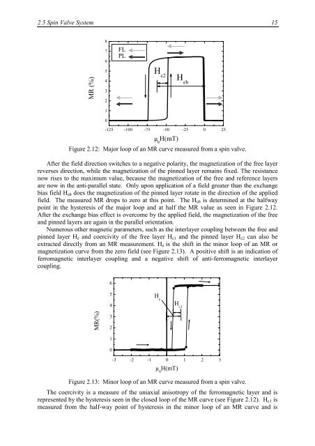
Figure 2.12: Major loop of an MR curve measured from a spin valve.<br />
After the field direction switches to a negative polarity, the magnetization of the free layer<br />
reverses direction, while the magnetization of the pinned layer remains fixed. The resistance<br />
now rises to the maximum value, because the magnetization of the free and reference layers<br />
are now in the anti-parallel state. Only upon application of a field greater than the exchange<br />
bias field Heb does the magnetization of the pinned layer rotate in the direction of the applied<br />
field. The measured MR drops to zero at this point. The Heb is determined at the halfway<br />
point in the hysteresis of the major loop and at half the MR value as seen in Figure 2.12.<br />
After the exchange bias effect is overcome by the applied field, the magnetization of the free<br />
and pinned layers are again in the parallel orientation.<br />
Numerous other magnetic parameters, such as the interlayer coupling between the free and<br />
pinned layer He and coercivity of the free layer Hc1 and the pinned layer Hc2 can also be<br />
extracted directly from an MR measurement. He is the shift in the minor loop of an MR or<br />
magnetization curve from the zero field (see Figure 2.13). A positive shift is an indication of<br />
ferromagnetic interlayer coupling and a negative shift of anti-ferromagnetic interlayer<br />
coupling.<br />
MR(%)<br />
6<br />
5<br />
4<br />
3<br />
2<br />
1<br />
0<br />
H e<br />
H c1<br />
-3 -2 -1 0 1 2 3<br />
µ 0 H(mT)<br />
Figure 2.13: Minor loop of an MR curve measured from a spin valve.<br />
The coercivity is a measure of the uniaxial anisotropy of the ferromagnetic layer and is<br />
represented by the hysteresis seen in the closed loop of the MR curve (see Figure 2.12). Hc1 is<br />
measured from the half-way point of hysteresis in the minor loop of an MR curve and is