MK 15 DR Ex - müller co-ax ag
MK 15 DR Ex - müller co-ax ag
MK 15 DR Ex - müller co-ax ag

You also want an ePaper? Increase the reach of your titles
YUMPU automatically turns print PDFs into web optimized ePapers that Google loves.
www.<strong>co</strong>-<strong>ax</strong>.<strong>co</strong>m<br />
Above stated body materials refer to<br />
the valve port <strong>co</strong>nnections that get in <strong>co</strong>ntact<br />
with the media only!<br />
details needed<br />
■ orifice<br />
■ port<br />
■ function NC/NO<br />
■ operating pressure<br />
■ inlet pressure at A, B or C<br />
■ flow rate<br />
■ media<br />
■ media temperature<br />
■ ambient temperature<br />
■ nominal volt<strong>ag</strong>e<br />
The valves‘ technical design is based<br />
on media and application requirements.<br />
This can lead to deviations from the general<br />
specifications shown on the data sheet with<br />
regards to the design, sealing materials and<br />
characteristics.<br />
If order or application specifications are<br />
in<strong>co</strong>mplete or imprecise there exists a risk of<br />
an in<strong>co</strong>rrect technical design of the valve for<br />
the required application. As a <strong>co</strong>nsequence,<br />
the physical and / or chemical properties of<br />
the materials or seals used, may not be suitable<br />
for the intended application.<br />
■ specifications not highlighted are standard<br />
specifications highlighted in grey are optional<br />
type<br />
3/2 way valve<br />
pressure range<br />
orifice<br />
<strong>co</strong>nnection<br />
function<br />
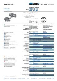
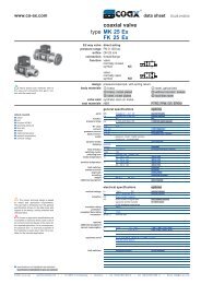
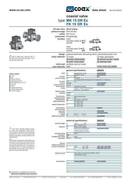
<strong>co</strong><strong>ax</strong>ial valve<br />
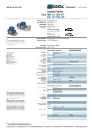
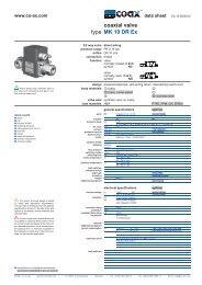
<strong>MK</strong> <strong>15</strong> <strong>DR</strong> <strong>Ex</strong><br />
FK <strong>15</strong> <strong>DR</strong> <strong>Ex</strong><br />
direct acting<br />
PN 0-40 bar<br />
DN <strong>15</strong> mm<br />
thread/flange<br />
valve<br />
normally closed (A ►B)<br />
symbol NC<br />
valve<br />
normally open (A ►B)<br />
symbol NO<br />
data sheet<br />
E4.16-01/2012<br />
<strong>müller</strong> <strong>co</strong>-<strong>ax</strong> <strong>ag</strong> • Gottfried-Müller-Str. 1 • D-74670 Forchtenberg • Germany • fon +49(0)7947/828-0 • f<strong>ax</strong> +49(0)7947/828-11 • Email info@<strong>co</strong>-<strong>ax</strong>.<strong>co</strong>m<br />
�<br />
�<br />
� �<br />
�<br />
� �<br />
�<br />
� �<br />
�<br />
design pressure balanced, with spring return, intersecting switch-over<br />
body materials � brass � steel, galvanized<br />
valve seat<br />
seal materials<br />
� brass, nickel plated � without non-ferr. metals<br />
� �<br />
�<br />
� steel, nickel plated � stainless steel<br />
synthetic resin on metal<br />
NBR PTFE, FPM, CR, EPDM<br />
general specifications options<br />
ports <strong>MK</strong> threads G 3/8 - G 3/4<br />
special threads<br />
FK flanges PN 16/40<br />
special flanges<br />
function NC NO<br />
pressure range bar 0-16/0-40<br />
Kv value m³/h<br />
A � B m<strong>ax</strong>.40 / B � A m<strong>ax</strong>.16 / A � C m<strong>ax</strong>.40 / C � A m<strong>ax</strong>.16<br />
4,3<br />
vacuum leak rate < 10-6 mbar•l•s-1 pressure-vacuum P1� P2 upon request<br />
back pressure P2 > P1 see pressure range<br />
media gaseous - liquid - highly vis<strong>co</strong>us -<br />
gelatinous - <strong>co</strong>ntaminated<br />
abrasive media upon request<br />
damping opening<br />
closing<br />
flow direction see pressure range<br />
switching cycles 1/min 200<br />
switching time ms opening 80 closing 80<br />
media temperature °C DC: -20 to +40<br />
AC: -20 to +40<br />
ambient temperature °C DC: -20 to +40<br />
AC: -20 to +40<br />
limit switches<br />
manual override<br />
inductive<br />
approvals LR/GL/WAZ<br />
mounting mounting brackets<br />
weight kg <strong>MK</strong> 4,3 FK 5,9<br />
additional equipment upon request<br />
electrical specifications options<br />
nominal volt<strong>ag</strong>e Un 24 V DC<br />
Un 230 V 40-60 Hz AC<br />
actuation DC direct-current m<strong>ag</strong>net<br />
AC direct-current m<strong>ag</strong>net with<br />
separate rectifier outside<br />
of the explosion-proof area<br />
insulation rating H 180°C<br />
protection IP65<br />
energized duty rating ED 100%<br />
<strong>co</strong>nnection M16x1,5 terminal box<br />
optional<br />
additional equipment<br />
current <strong>co</strong>nsumption<br />
explosion proof<br />
Un V-DC 24 200<br />
In A 1,20 0,<strong>15</strong><br />
II 2 G Eex m II T4 and II 2 D IP65 T 130°C<br />
PTB 02 ATEX 2120 X<br />
special volt<strong>ag</strong>e<br />
special volt<strong>ag</strong>e<br />
sand sealed rectifier<br />
48 98 110 220<br />
0,60 0,30 0,28 0,14<br />
limit switches inductive NAMUR circuit amplifier
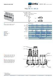
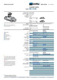
type <strong>MK</strong> <strong>15</strong> <strong>DR</strong> <strong>Ex</strong><br />
���<br />
��<br />
��<br />
� �<br />
��<br />
�<br />
��<br />
�� �� ��<br />
�<br />
�����<br />
function: NC<br />
closed when not energized (A ►B)<br />
���<br />
��<br />
type FK <strong>15</strong> <strong>DR</strong> <strong>Ex</strong> function: NO<br />
open when not energized (A ►B)<br />
�� ���<br />
��<br />
� �<br />
��<br />
�<br />
��<br />
�� �� ��<br />
��<br />
��<br />
���<br />
The application-specific layout relating to temperature, pressure <strong>co</strong>nditions, switching behavior, media and its <strong>co</strong>nsistency<br />
may restrict the range of use or necessitate relevant modifications to materials used and seal arrangements.<br />
Rights reserved to make technical alterations • Not responsible for printing errors • Detailled drawings can be obtained upon request<br />
��<br />
��<br />
�<br />
�<br />
<strong>co</strong>nstructive length<br />
standard<br />
�<br />
flanges PN<br />
16<br />
DIN<br />
2633<br />
L1<br />
210<br />
ØD<br />
95<br />
L2<br />
138<br />
Øk<br />
65<br />
L3<br />
266<br />
with 1/2 inductive limit switches 259 187 3<strong>15</strong><br />
Ød<br />
14<br />
40 2635 95 65 14